


PTAC
WIRELESS KITS (DT01G, DS01E, DD01E)
INSTALLATION INSTRUCTIONS
AIR CONDITIONING SENSOR
DD01E
Heating & Air Conditioning |
|
A |
® |
|
DS01E
DT01G
The following installation instructions are for a typical installation. Please contact your PTAC salesperson
for additional assistance and explanation prior to ordering materials or cutting openings.
ATTENTION INSTALLING PERSONNEL
As a professional installer you have an obligation to know the product better than the customer. This includes all safety precautions and related items.
Prior to actual installation, thoroughly familiarize yourself with this Instruction Manual. Pay special attention to all safety warnings. Often during installation or repair
it is possible to place yourself in a position which is more hazardous than when the unit is in operation.
Remember, it is your responsibility to install the product safely and to know it well enough to be able to instruct a customer in its safe use.
Safety is a matter of common sense...a matter of thinking before acting. Most dealers have a list of specific good safety practices...follow them.
The precautions listed in this Installation Manual are intended as supplemental to existing practices. However, if there is a direct conflict between existing practices and the content of this manual, the precautions listed here take precedence.


 is a registered trademark of Maytag Corporation or its related companies and is used under license to Goodman Company, L.P., Houston, TX. All rights reserved.
|
Goodman Company, L.P. |
|
|
|
|
|
|
|
|
|
|
August 2010 |
5151 San Felipe, Suite 500 • Houston, TX 77056 |
|
|
|
|
|
|
|
|
|
|
IO-729A |
www.amana-ptac.com • © 2009-2010 Goodman Company, L.P. |
|
|
|
|
|
|
|
|
|
|
|
|
|
|
|
|
|
|
|
|
|
|
Due to policy of continued product improvement, the right is reserved to change specifications and design without notice.
BEFORE BEGINNING INSTALLATION, PLEASE READ IMPORTANT NOTES BELOW:
•If devices are to be powered, field installed wiring will need to be run from thermostat location to unit location and from door sensor location to PTAC location and from wired magnet to sensor location.
•If wireless platform DP01G, DP01E or DL01E are being utilized, then room numbers MUST BE CONFIGURED in the control board prior to binding wireless devices.
•All units must have DT01G antenna for wireless devices to communicate properly.
Sequence of installation:
•1) Mount the peripherals
2)Verify operation of the door sensor
3)Program room numbers
4)Bind peripherals
5)Reattach peripherals to their mounted backplates
6)Install optional security screws
•Installation and videos are available on our website at www.amana-ptac.com.
•Use only one DD01E Passive Infrared Motion Sensor (PIR) door switch combination device and/or one DS01E to one DigiSmart™ PTAC unit.
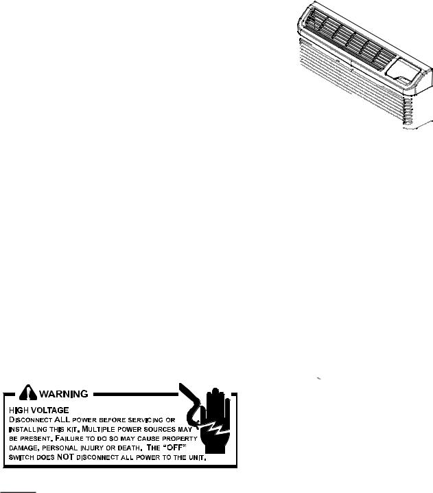
Front Mounting Screw accessed
through louvers.
3.Remove cabinet front from chassis by tilting the bottom of the front forward, lifting slightly up and forward.
4.Mount the antenna as high up on the control panel as possible and as far to the right as possible in a location that will not interfere with the reinstallation of the PTAC polymer room front. Mark holes for screw location. Remove antenna housing and drill two 1/8” holes where marked. Some units may have the holes already predrilled in the correct location.
Antenna Installation For DT01G Kit
Wire
A DT01* antenna must be installed on the digital PTAC to allow operation of either the DS01* remote RF thermostat or a DD01* combination PIR motion sensor and door switch.
Preparation
1.Disconnect power to the unit by unplugging the power cord at the wall outlet or subbase, or disconnect power at the fuse box or circuit breaker.
2.If the cabinet front is screwed to the chassis, remove the 1/4” screw (or screws). See following figure.
2
DT01* Mounting
5.Remove antenna cable and route cable through opening in bottom of antenna housing.
6.Mount antenna housing with two screws as shown in figure. (NOTE: The Amana® brand logo should be in the lower right hand corner).
7.Plug wire harness from antenna into connector on the control board to the right of the master switch, being careful not to bend and/or break the wires when you connect the cable to the PTAC. Gently push the connector into place by pushing on the edge of the connector with your thumb nails. Avoid pushing directly on the wires.
8.Restore power to the PTAC unit.
9.Reinstall the polymer room cover.
NOTE: The LED must be oriented at the top of the antenna housing (the Amana® brand logo will be on the lower right) for proper unit operation.
Thermostat Installation for DS01E Kit
NOTE: A DT01* must be installed on the digital PTAC unit for the DS01* to be operable.
Skip these steps if not installing.
1.Select thermostat mounting location about five feet above the floor, on an inside wall, out of direct sunlight, away from sources of radiant heat (lamps, fireplaces, heating and air conditioning equipment, etc.), away from windows or door to the outside, and avoid areas with poor air circulation. If the PIR in the thermostat is to be used with a DD01* device as a 2nd motion sensor, point the thermostat towards the area where you are requiring additional motion sensing.
Ensure location is out of the path of foot traffic where a person might accidentally bump into the thermostats and damage the device.
2.Remove thermostat from mounting plate by pulling apart at the bottom of the thermostat about 1”, and slide thermostat up to release from the top of the mounting plate.
3.Place thermostat mounting plate against the wall at desired location and mark placement of mounting holes. Make sure the UP arrow is pointing up on the mounting plate.
4.If mounting in drywall, tap plastic anchors into wall. For other surfaces, drill a 3/16” hole.
5.Screw mounting plate to the wall. DO NOT SNAP THERMOSTAT INTO PLACE UNTIL AFTER BINDING PROCESS.
See Binding Instructions on page 10.
6.Install four (4) AA batteries (included) into the back of the thermostat. Terminals are marked “+” and “-” for polarity.
NOTE: Do not install thermostat on wall plate until all configuration settings and binding processes have been completed.
WIRED POWER OPTION
1.If the option for wired power is used, the two thermostat wires (20 gauge minimum field supplied) can be connected to the thermostat.
2.Route wires through the opening in the mounting plate.
3.Loosen set screws on wired terminal and insert wires into the opening. Tighten set screws. (See following figure for powered connection with 2 jumpers).
4.Connect wires at PTAC unit to terminal pins C and R. The wire harness kit PWHK01C is required for this connection.
TWO JUMPERS FACTORY DEFAULT “BATTERY”
BATTERY CONNECTION
NOTE: For battery connection the 2 jumpers must be positioned as shown above, with jumpers on the center & left pins.
TERMINAL BLOCK
TWO JUMPERS MOVED TO
“EXT POWR”
POWERED CONNECTION
NOTE: For powered connection, the 2 jumpers must be positioned as shown above, with jumpers on the center & right pins.
3
Mounting Sensor/Door Magnet Installation |
WIRED MAGNET AND POWERED DOOR |
for DD01E Kit |
SENSOR OPTION |
DD01E must be mounted on the top door frame as close to the door as possible in the horizontal position.
A DT01E must be installed in the PTAC unit for the DD01E to be operable.
Skip these steps if not installing.
1.Remove motion sensor from mounting plate by pulling apart.
2.Mount the back plate on the door trim directly above the door using the enclosed screws. (Position so the UP arrow is pointing up.) Mount the DD01E as low as possible on the door frame to be as close to the moving part of the door as possible without interfering with the door opening or closing. Choose a location for mounting the back plate that will provide good coverage of the PIR for motion into the room. Make sure that the DD01E will not interfere with the normal opening and closing of the door.
DO NOT SNAP MOTION SENSOR IN PLACE UNTIL AFTER BINDING PROCESS.
See Binding Instructions, page 10.
DD01*
DOOR TRIM
DOOR
(CENTER MAGNET WITH DD01*)
DD01E Mounting
3.Install two (2) AA batteries (included) into the back of the thermostat. Terminals are marked “+” and “-” for polarity. Do NOT put batteries into the device until
AFTER the magnet location is selected to test.
In cases where there is no top door frame, the sensor will need to be mounted on the wall next to the door. In these cases a wired magnet (a field supplied single pole single throw wired magnet) can be recessed or surface mounted and wired to the door sensor. The magnet will be a recessed style magnet with wired switch. The wires for the sensor (20 gauge field supplied) in the magnet will need to be run during construction. Two wires will be run from the door sensor location to the PTAC unit; the remaining two wires will be run from the magnet location to the sensor location. The door sensor has four (4) terminal locations for wired power and/or wired magnets. The two (2) terminals closest to the binding button are for wired magnet and the top two
(2) terminals are for wired power.
Run the magnet wires through the opening in the center of the door sensor wall plate.
CONNECTING MAGNET
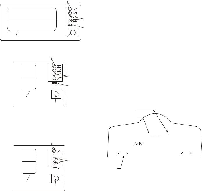
Using a pocket size straight blade screw driver push down on the terminal button to open the socket, insert wire into socket and release the terminal button. Insert one wire into each of the two (2) terminals. See image below for wire locations.
POWER CONNECTION
If using the wired powered option for the door sensor, using a pocket size straight blade screw driver, push down on the terminal button to open the socket. Insert wire into socket and release the terminal button. Insert one wire into each of the two (2) terminals. See following for wire locations. Connect the power wires from the door sensor to the PTAC on terminals C & R. The wire harness kit PWHK01C is required for this connection.
4
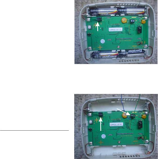
Viewed from the back with the power block in upper right corner.
+ |
- |
Wired |
|
|
Magnet |
- |
+ |
Connection |
Pins |
||
Battery Holder |
Binding Button |
|
Power Connection
- |
Wired |
|
|
Magnet |
|
+ |
Connection |
|
Jumper |
||
|
on Pins |
|
|
Battery |
|
Battery |
Connection |
|
Binding Button |
||
Holder |
Note: For battery connection, the jumper must be placed as shown above
Door Magnet Installation
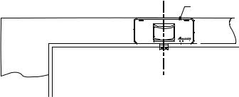
NOTE: Magnet buckets are shipped from the factory with the magnets in position A. The position may change based on the door and door frame alignment on page 6.
Mount the door magnet holder on the front of the door where it will be as close as possible to the bottom of the motion sensor but no more then 1/8" from the bottom center of the motion sensor (DD01E) when the door is closed.
Select the correct slot in the magnet holder (there are three slots) to obtain 15/16" from back of sensor mounting plate to the center of the magnet. (If you can easily slide a business card between the magnet and the DD01E sensor, unit is properly placed vertically.) See image below for magnet and sensor alignment.
Screw in place with the 2 screws provided. Open and close the door to make sure that the magnet holder and motion sensor will not interfere with normal opening and closing of the door. See images on pages five and six.
ALIGNMENT
GUIDES
ON BOTTOM
OF DD01E
Power Connection
- 
 Wired
Wired
Magnet
+ JumperConnection
|
on Pins |
|
|
Powered |
|
Battery |
Connection |
|
Binding Button |
||
Holder |
|
|
|
|
|
|
|
|
|
|
|
|
|
|
|
|
|
|
|
|
|
|
|
|
|
|
|
|
|
|
|
|
|
|
|
|
|
|
|
|
|
|
|
|
|
|
|
|
|
|
|
|
|
|
|
|
|
|
|
|
|
|
|
|
|
|
|
|
|
|
|
|
|
|
|
|
|
|
|
|
|
|
|
|
|
|
|
|
|
|
|
|
|
|
|
|
|
|
|
|
|
|
|
|
|
|
|
|
|
|
|
|
|
|
|
|
|
|
|
|
|
|
|
|
|
|
CENTER OF MAGNET |
||||||||
SENSOR |
|
|
|
|
(IN HOLDER) |
|||||||||
|
|
|
MUST BE 15/16” FROM THE |
|||||||||||
MOUNTING |
|
|
|
|||||||||||
PLATE |
|
|
|
SENSOR MOUNTING PLATE |
||||||||||
|
|
|
|
|
|
|||||||||
Do NOT install batteries until you are ready to test the magnet location with DD01E.
Note: For 24v powered connection, the jumper must be placed as shown above
5
 Loading...