


A1200S
Amana A1200S, P4020003901, P1185701M, FS10EVP, FS10EVP.000 Service
...
Service
Commercial
Microwave
Oven
This manual replaces RE220002 Rev . 5.
This manual is to be used by qualified appliance
technicians only. Amana does not assume any
responsibility for property damage or personal
injury for improper service procedures done by
an unqualified person.
Models and manufacturing
numbers in this manual are
located below and on page 4.
A1200S P4020008302
A1225S P1185701M
FS10EVP P4020003901
FS10EVP.000
FS10EVP.A
FS10EVP.B
FS10EVP.C
FS10EVP.D
FS10EVP.E
FS10EVP.F
FS11 P1302104M
FS11EVP P1186001M
FS14EVP P4020004901
FS14EVP.000
FS14EVP.A
FS14EVP.B
FS14EVP.C
FS14EVP.D
FS14EVP.E
FS14EVP.F
FS16EVP P1185901M
FS17 P1302105M
FS17EVP P1185902M
FS20 P1302106M
FS20EVP P1185903M
FSP10 P4020004102
FSP10.A
FSP10.B
FSP10.C
FSP10.D
FSP10.E
FSP10SS P4020004103
FSP11 P1185802M
FSP11 P1302102M
FSP11LW P1302103M
FSP11LW P1185805M
FSP11SS P1185803M
VEND10 P4020004101
VEND10.000
VEND10.A
VEND10.B
VEND10.C
VEND10.F
VEND10.G
VEND10.H
VEND10.J
VEND10.K
VEND10.L
VEND11 P1185801M
VEND11B P1185804M
VEND11 P1302101M
RE220002
Revison 6
March 1999

!
!
!
Important Product Information
WA R N ING
Precautions to be observed before and during
servicing to avoid possible exposure to excessive
microwave energy .
(A) Do not operate or allow oven to be operated with
the door open.
(B) Make the following safety checks on all ovens to be
serviced before activating the magnetron or other
microwave source, and make repairs as
necessary:
• Interlock operation
• Proper door closing
• Seal and sealing surfaces (arcing, wear, and other
damage)
• Damage to or loosening of hinges and latches
• Evidence of dropping or abuse
(C) Before turning on microwave power for any service
test or inspection within the microwave generating
compartments, check the magnetron, wave guide
or transmission line, and cavity for proper
alignment, integrity , and connections.
(D) Any defective or misadjusted components in the
interlock, monitor, door seal, and microwave
generation and transmission systems shall be
repaired, replaced, or adjusted by procedures
described in this manual before oven is released to
the consumer.
(E) Check microwave leakage to verify compliance
with the Federal Performance Standard should be
performed on each oven prior to release to the
consumer.
WARNING
To avoid risk of electrical shock, injury, or death, make
sure these grounding instructions are followed.
Grounding Instructions
WA RN IN G
Do not remove grounding prong when installing
grounded appliance in a home or business that does
not have three wire grounding receptacle, under no
condition is grounding prong to be cut off or removed.
It is the personal responsibility of the consumer to
contact a qualified electrician and have properly
grounded three prong wall receptacle installed in
accordance with appropriate electrical codes
Should a two prong adapter plug be required temporarily it
is the personal responsibility of the consumer to have it
replaced with properly grounded three prong receptacle or
the two prong adapter properly grounded by a qualified
electrician in accordance with appropriate electrical codes.
Servicing of Grounded Products
The standard accepted color coding for grounding wires is
GREEN or GREEN WITH YELLOW STRIPE. These
ground leads are NOT to be used as current carrying
conductors. It is extremely important that the technician
replace any and all grounds prior to completion of the
service call. Under no condition should ground wire be left
off causing a potential hazard to technicians and consumer.
WIRING
Good service practice is to never route wiring over terminals and/or sharp edges. This applies to any wiring without
regard to the circuit voltage. Wire insulation material and
thickness is designed and regulated for electrical spacing
purpose only, but cannot always be relied upon because of
possible cuts and/or abrasions, which can occur during
servicing.
RE220002 Rev. 6 2

Table of Contents
IMPORTANT PRODUCT INFORMATION........................................................................................................ 2
MODEL AND MANUFACTURING NUMBERS.................................................................................................4
IMPORTANT SAFETY INFORMATION ........................................................................................................... 6
IMPORTANT PRODUCT GROUNDING AND OUTLET INFORMATION ................................................... 7
SPECIFICATIONS............................................................................................................................................ 9
CAUTIONS AND WARNINGS to be Observed During Disassembly and Troubleshooting ............................. 10
GENERAL INFORMATION AND OPERATING INSTRUCTIONS.................................................................... 11
TEST PROCEDURES......................................................................................................................................13
DISASSEMBLY PROCEDURES......................................................................................................... .............21
SERVICE INFORMATION................................................................................................................................28
PROCEDURE FOR MEASURING MICROWAVE ENERGY LEAKAGE ..........................................................29
TROUBLESHOOTING .....................................................................................................................................30
VEND-10, 1 1 PROGRAMMING INSTRUCTIONS ...........................................................................................41
FS-10, 1 1, 14, 16 PROGRAMMING INSTRUCTIONS.....................................................................................45
FSP-10, 1 1 PROGRAMMING INSTRUCTIONS ..............................................................................................48
A1200S, A1225S PROGRAMMING INSTRUCTIONS .................................................................................... 50
SCROLLING MESSAGE PROCEDURE ..........................................................................................................55
WIRING SCHEMATIC/DIAGRAM ....................................................................................................................56
REPLACE MANUAL C-SM033 WITH THIS MANUAL, RE220002.
REV. 1—ADDED MODEL FSP10SS, P4020004103 TO MANUAL. THIS MODEL IS SIMILAR TO MODEL
FSP10, P4020004102.
REV. 2—ADDED MODEL FSP11SS, P1185803M TO MANUAL. THIS MODEL IS SIMILAR TO MODEL
FSP1 1, P1 185802M.
REV. 3—ADDED MODEL VEND1 1B, P1185804M, P1302101M; FSP1 1SS, P1302102M; FSP11L W, P1302103M;
FSP11EVP, P1302104M; FS17EVP, P1302105M; AND FS20EVP, P1302106M T O MANUAL.
REV.4—ADDED MODELS FS17EVP, P1185902M; AND FS20EVP, P1185903M TO THIS MANUAL.
REV. 5—CORRECTED MODEL INDENTIFICATION FS17EVP T O FS17; FS20EVP TO FS20; FSP11EVP TO
FSP11; FS11SS TO FS11; AND VEND11B TO VEND 11 ALONG WITH ASSOCIATED TEXT. ADDED
FSP11L W , P1 185805M.
REV. 6—CORRECTED MODELS ASSIGNED TO WIRING DIAGRAM, AND ADDED NEW CONTROLLER
TESTING PROCEDURE.
3 RE220002 Rev. 6

Models and Manufacturing Numbers
NOTE: For easier identification, the MODEL numbers are in alpha numerical order.
MODEL M/N
A1200S P4020008302
A1225S P1185701M
FS10EVP P4020003901
FS10EVP.000
FS10EVP.A
FS10EVP.B
FS10EVP.C
FS10EVP.D
FS10EVP.E
FS10EVP.F
FS11 P1302104M
FS11EVP P1186001M
MODEL M/N
FS14EVP P4020004901
FS14EVP.000
FS14EVP.A
FS14EVP.B
FS14EVP.C
FS14EVP.D
FS14EVP.E
FS14EVP.F
FS16EVP P1185901M
FS17 P1302105M
FS17EVP P1185902M
FS20 P1302106M
FS20EVP P1185903M
FSP10 P4020004102
FSP10.A
FSP10.B
FSP10.C
FSP10.D
FSP10.E
FSP10SS P4020004103
FSP11 P1185802M
FSP11LW P1185805M
FSP11LW P1302103M
FSP11SS P1185803M
MODEL M/N
VEND10 P4020004101
VEND10.000
VEND10.A
VEND10.B
VEND10.C
VEND10.F
VEND10.G
VEND10.H
VEND10.J
VEND10.K
VEND10.L
VEND11 P1185801M
VEND11B P1185804M
VEND11 P1302101M
RE220002 Rev. 6 4

Important Information
!
!
!
!
!
Pride and workmanship go into every product to provide our customers with quality products. It is possible,
however, that during its lifetime a product may require service. Products should be serviced only by a qualified
service technician who is familiar with the safety procedures required in the repair and who is equipped with the
proper tools, parts, testing instruments and the appropriate service manual. REVIEW ALL SERVICE INFORMATION
IN THE APPROPRIATE SERVICE MANUAL BEFORE BEGINNING REPAIRS.
Important Notices for Consumers and Servicers
WARNING
To avoid risk of serious injury or death, repairs should not be attempted by an unauthorized personal, dangerous
conditions (such as exposure to electrical shock) may result.
CAUTION
Amana will not be responsible for any injury or property damage from improper service procedures. If performing
service on your own product, assume responsibility for any personal injury or property damage which may result.
To locate an authorized servicer, please consult your telephone book or the dealer from whom you purchased this
product. For further assistance, contact 1 (800) 628-5782 first, if no answer contact the following number.
CONSUMER AFFAIRS DEPT. OR 1 (800) 843-0304
AMANA CALL
AMANA, IOWA 52204
If outside the United States contact:
AMANA
ATTN: CONSUMER AFFAIRS DEPT
2800 220th Trail
AMANA, IOWA 52204, USA
Telephone: (319) 622-5511
Facsimile: (319) 622-2180
TELEX: 4330076 AMANA
CABLE: "AMANA", AMANA, IOWA, USA
Recognize Safety Symbols, Words, and Labels
DANGER
DANGER—Immediate hazards which WILL result in severe personal injury or death.
WA RN IN G
WARNING—Hazards or unsafe practices which COULD result in severe personal injury or death.
CAUTION
CAUTION—Hazards or unsafe practices which COULD result in minor personal injury or product or property
damage.
5 RE220002 Rev. 6

!
Important Safety Information
CAUTION
Do not become exposed to radiation from the
microwave generator or other parts conducting
microwave energy .
Basic design of this microwave oven makes it an
inherently safe device to both use and service. However,
there are some precautions which should be followed
when servicing microwave oven to maintain this safety .
These are as follows:
1. Always operate unit from an adequately grounded
outlet. Do not operate on a two-wire extension cord.
2. Before servicing unit (if unit is operable) perform
microwave leakage test.
3. Oven should never be operated if door does not fit
properly against seal, hinge/hinge bearings are
damaged or broken; choke is damaged, (pieces
missing, etc.); or any other visible damage can be
noted. Check choke area to ensure that this area is
clean and free of all foreign matter . If any above
problems occur take the following steps:
• Tell the user not to operate the oven.
• Contact Amana immediately .
4. If oven operates with door open and produces
microwave energy , take the following steps:
• Tell the user not to operate the oven.
• Contact Amana immediately .
5. Always have oven disconnected when outer case is
removed except when making "live" tests called for in
the service manual. Do not reach into equipment
area while unit is energized. Make all connections for
the test and check them for tightness before plugging
cord into outlet.
6. Always ground capacitors on magnetron filter box
and H.V . capacitor with an insulated-handle
screwdriver before working in high voltage area of
equipment compartment. Some types of failures will
leave a charge in capacitors and the discharge could
cause a reflex action which could make you injure
yourself.
7. In the area of the transformer, capacitor , diode, and
magnetron there is HIGH VOLTAGE. When unit is
operating, keep area clean and free of anything
which could possibly cause an arc or ground, etc.
8. DO NOT for any reason defeat interlock switches,
there is no valid reason for this action at any time; nor
will it be condoned by Amana.
9. Microwave oven should never be operated with:
• Any components removed and/or bypassed
• Any of the safety interlocks are found to be defective
• Any of the seal surfaces are defective, missing, or
damaged
10.To ensure that unit does not emit excessive
microwave leakage and to meet Department of
Health and Human Services guidelines check oven
for microwave leakage using Narda Model 8100,
8200, Holaday HI1500, HI1501, or Simpson 380M
leakage monitor as outlined in instructions. Maximum
leakage level allowed is 4mw/cm2 .
11.If servicer encounters an emission reading over 4mw/
cm2, servicer is to cease repair and contact Amana
Service Department immediately for further direction.
Amana will contact the proper Government Agency
upon verification of test results.
12.Install or locate this equipment ONLY in accordance
with the installation instructions in this manual.
13.Some products such as whole eggs and sealed
containers – for example, closed glass jars – may
explode and SHOULD NOT be HEA TED in this
equipment.
14.Use this equipment ONL Y for its intended use as
described in this manual. Do not use corrosive
chemicals or vapors in this equipment. This type of
equipment is specifically designed to heat or cook. It
is not designed for industrial or laboratory use.
15.As with any equipment, CLOSE SUPERVISION is
necessary when used by CHILDREN.
16.DO NOT operate this equipment if it has a damaged
cord or plug, if it is not working properly , or if it has
been damaged or dropped.
17.This equipment, including power cord, must be
serviced ONLY by qualified service personnel.
Special tools are required to service equipment.
Contact nearest authorized service facility for
examination, repair , or adjustment.
18.DO NOT cover or block any openings on the
equipment.
19.DO NOT store this equipment outdoors. DO NOT
use this product near water – for example, near a
kitchen sink, in a wet basement, or near a swimming
pool, and the like.
20.DO NOT immerse cord or plug in water.
21.Keep cord AWAY from HEATED surfaces.
22.DO NOT let cord hang over edge of table or counter.
RE220002 Rev. 6 6

Important Product Grounding and Outlet Information
Typical grounding
type wall receptacle
Typical power supply
cord with 3-prong
grounding plug
Typical type wall receptacle
Typical power supply
cord with 3-prong
grounding plug
Temporary grounding adapter
(NOT used in Canada)
NOTE: 120 V olt, 15 A. Cord and Receptacle shown.
Typical instructions also apply to 120 V, 20 AMP, and
208/240 V cords and receptacles.
Proper grounding and polarization of 120 V wall outlets.
Explanations
Polarization—This means that the larger slot must be
neutral and the small slot must be hot (live).
Mispolarized—The outlet is miswired so that the larger
slot is hot (live) and the smaller slot is neutral.
Grounded—This means the round hole connection is
connected to earth ground through a connection to the
main power panel.
Ungrounded—The round hole connection is not
complete to earth ground and/or the main power panel.
FIGURE 1
For the safety of our customers and the service
technician ALL appliances having a three (3) prong
power cord MUST be connected to a properly polarized
AND grounded wall outlet.
This information was written for those who do not
understand grounding and polarization of a wall outlet.
A 120 Volt wall outlet must always be wired as shown in
Figure 1.
7 RE220002 Rev. 6

Important Product Grounding and Outlet Information
!
Test Procedures (2 Methods)
Method 1
Purchase and use a ground monitor (Figure 2, Page 8)
available under Amana Part Number R0193001 or it can
be purchased locally . The lamps inside the monitor
indicates a correctly or incorrectly wired outlet by
instructions imprinted on the monitor body .
Method 2
Voltmeter - (Use scale over 125 Volts A.C.)
Test A - "H" to "N" must indicate line voltage.
Test B - "H" to "G" must indicate line voltage.
Test C - "N" to "G" must indicate zero (0) volts.
If "N" to "G" indicates line voltage the outlet is
mispolarized.
If "H" to "G" indicates zero (0) volts the outlet is not
grounded.
FIGURE 2
WARNING
Wiring changes or grounding of wall outlet are to be
made only by a qualified electrician.
In the event a grounding adaptor (not used in Canada)
has been TEMPORARILY installed the test procedures
described in Methods 1 and 2 above should be used
(Figure 3).
FIGURE 3
NOTE: The green wire or tab should be connected to a
proper ground by a qualified electrician.
General Test Information
Most testing in the manual is conducted with an
ohmmeter using a multiplier scale of X10k (k-thousand
ohms). When using this scale, it is important that your
fingers do not touch the metal parts of the test probes.
To do so will give a false indicate of the ohm reading.
RE220002 Rev. 6 8

Specifications
Models
Power Source
Voltage AC
Amperage
(Single Unit)
Frequency
Single Phase
(3 Wire Earthed)
Power Output
Standard Test
IEC 705 Test
Operating Frequen cy
Power Consumption
Standby Condition
Idle Condition
Cook Condition
Dimemsions
Cabinet
Width
Height
Depth
Cooking Cabinet
Capacity
Width
Height
Depth
Power Cord
NEMA
A1200S A1225S FS10EVP
120 120 120 120 208/240 208/240 208/230 208/230 120 120
20 20 20 20 20 20 20 20 20 20
60 Hz 60 Hz 60 Hz 60 Hz 60 Hz 60 Hz 60 Hz 60 Hz 60 Hz 60 Hz
Yes Yes Yes Yes Yes Yes Yes Yes Yes Yes
1100 W 1100 W 1100 W 1100 W 1400 W 1500 W 1600 W 1900 W 1100 W 1100 W
1200 W 1200 W 1200 W 1200 W 1500 W 1600 W 1700 W 2000 W 1200 W 1200 W
2450 MHz 2450 MHz 2450 MHz 2450 MHz 2450 MHz 2450 MHz 2450 MHz 2450 MHz 2450 MHz 2450 MHz
0000000000
200 W 200 W 200 W 200 W 300 W 300 W 300 W 300 W 200 W 200 W
2100 W 2100 W 2100 W 2100 W 2800 W 2800 W 2800 W 2800 W 2100 W 2100 W
20.5”
52.1cm
14.9”
37.8cm
21”
53.34cm
.75 cu ft
.02 cu m
12.8”
32.5cm
7.8”
19.8cm
13”
33cm
5-20R 5-20R 5-20R 5-20R 6-20R 6-20R 6-20R 6-20R 5-20R 5-20R
20.5”
52.1cm
14.9”
37.8cm
21”
53.34cm
.75 cu ft
.02 cu m
12.8”
32.5cm
7.8”
19.8cm
13”
33cm
FSP10
FSP11
20.5”
52.1cm
14.9”
37.8cm
21”
53.34cm
.75 cu ft
.02 cu m
12.8”
32.5cm
7.8”
19.8cm
13”
33cm
FS11
FS11EVP
20.5”
52.1cm
14.9”
37.8cm
21”
53.34cm
.75 cu ft
.02 cu m
12.8”
32.5cm
7.8”
19.8cm
13”
33cm
FS14EVP FS16EVP FS17
20.5”
52.1cm
14.9”
37.8cm
21”
53.34cm
.75 cu ft
.02 cu m
12.8”
32.5cm
7.8”
19.8cm
13”
33cm
20.5”
52.1cm
14.9”
37.8cm
53.34cm
.75 cu ft
.02 cu m
12.8”
32.5cm
19.8cm
33cm
21”
7.8”
13”
FS17EVP
20.5”
52.1cm
14.9”
37.8cm
21”
53.34cm
.75 cu ft
.02 cu m
12.8”
32.5cm
7.8”
19.8cm
13”
33cm
FS20
FS20EVP
20.5”
52.1cm
14.9”
37.8cm
21”
53.34cm
.75 cu ft
.02 cu m
12.8”
32.5cm
7.8”
19.8cm
13”
33cm
VEND10 VEND11
20.5”
52.1cm
14.9”
37.8cm
21”
53.34cm
.75 cu ft
.02 cu m
12.8”
32.5cm
7.8”
19.8cm
13”
33cm
20.5”
52.1cm
14.9”
37.8cm
21”
53.34cm
.75 cu ft
.02 cu m
12.8”
32.5cm
7.8”
19.8cm
13”
33cm
Adjust tap connector to either 208 or 230/240 volt source on the following models:
FS14EVP
FS16EVP
FS17
FS17EVP
FS20
FS20EVP
9 RE220002 Rev. 6

CAUTIONS and WARNINGS to be Observed During
!
!
!
!
!
!
Disassembly and Troubleshooting
Unlike many other appliances, the microwave oven is
high-voltage, high-current equipment. Though it is free
from danger in ordinary use, extreme care should be
taken during repair .
CAUTION
Servicemen should remove their watches whenever
working close to or replacing the magnetron.
Checking the ground
Do not operate on a 2-wire extension cord. The
microwave oven is designed to be used when grounded,
it is imperative, therefore, to make sure it is grounded
properly before beginning repair work.
WARNING
After the oven is turned off, an electric charge may
remain in the high voltage capacitor . When replacing
or checking parts, remove the power plug from the
outlet and short the terminal of the high voltage
capacitor (terminal of lead wire from diode) to chassis
ground with an insulated handle screwdriver and
discharge.
DANGER
There is high voltage present, with high current
capabilities in the circuits of the high voltage winding
and filament winding of the high voltage transformer . It
is extremely dangerous to work on or near these
circuits with the oven energized. Do not measure the
voltage in the high voltage circuit including filament
voltage of the magnetron.
When parts must be replaced, remove the power cord
from the outlet.
WARNING
When the fuse is blown due to the operation of the
monitor switch, replacement of complete interlock
switch must be performed.
1. This is mandatory. Refer to page 29 for the
necessary adjustments for this switch assembly .
2. When replacing the fuse, confirm that it has the
appropriate rating for these models.
CAUTION
Avoid inserting nails, wire, etc. through and holes in
the unit during operation.
Never insert a wire, nail, or any other metal object
through the lamp holes on the cavity or any other holes
or gaps because such object may work as an antenna
and cause microwave leakage.
Confirm After Repair
1. After repair or replacement of parts, make sure that
the screws of the oven, etc. are neither loose nor
missing.
2. Make sure that all electrical connections are tight
before inserting the plug into the wall outlet.
3. Check for microwave leakage. (Refer to procedure
for measuring microwave leakage.)
WARNING
Never touch any circuit with your hand nor with an
insulated tool during operation.
RE220002 Rev. 6 10
General Information and Operating Instructions
!
!
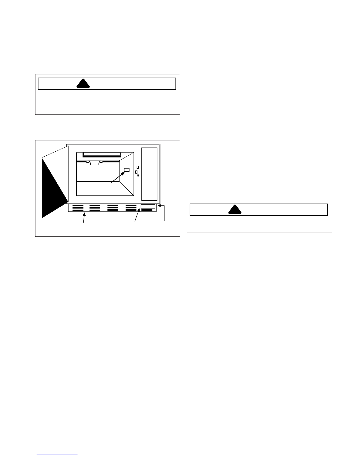
Service Access
Component servicing is done by lowering the back panel,
removing the control panel assembly , and component
module panel. Refer to the disassembly section for
specific components replacement and adjustment
procedures.
WARNING
All component mounting panels must be grounded to
the oven chassis before performing any
troubleshooting.
Serial Plate Location
Some models
5. The FS14EVP , FS16EVP, FS17, FS17EVP, FS20,
FS20EVP oven must be adjusted to the proper supply
voltage. This oven is manufactured preset for 240
volts. If the supply voltage is less than 220 volts,
remove the small cover on the back of the oven and
move the voltage adjusting connector to the 208 volt
tap connector. Incorrect tap setting can cause
component damage.
6. Plug the FS10 EVP, FSP10, FSP11, FSP11SS and
VEND10 oven into a standard 120 volt outlet. Plug the
FS14 EVP, FS16EVP, FS17, FS17EVP, FS20,
FS20EVP into a 208 or 240 volt outlet. Be sure the
electrical outlet is rated for at least 20 amperes and
the microwave oven is the only appliance on the
circuit.
Important Electrical Grounding Instructions
This appliance must be grounded. In the event of an
electrical short circuit, grounding reduces the risk of
electric shock by providing an escape wire for the electric
current. This appliance is equipped with a cord having a
grounding wire with a grounding plug. The plug must be
plugged into an outlet that is properly installed and
grounded.
Filter
Some models
Installation Instructions
1. Unpack the oven carefully and examine it for shipping
damage. If damage is evident, notify the local carrier
immediately and file a damage claim. Menumaster
assumes no liability for damage incurred in transit.
2. If the oven has been stored in an extremely cold area,
wait several hours before plugging the oven into an
outlet.
3. Remove all material from the oven interior.
4. Place the oven in the chosen location. Make sure
there is at least one inch of clearance on the top and
side and the air intake (filter) is not close to a high
temperature source. Example: A deep fat fryer.
WARNING
Improper use of the grounding plug can result in a risk
of electric shock.
Consult a qualified electrician or serviceman if the
grounding instructions are not completely understood, or if
doubt exists as to whether the appliance is properly
grounded.
If it is necessary to use an extension cord, use only a
three-wire extension cord that has a three-blade grounding
plug, and a three-slot receptacle that will accept the plug
on the appliance. The marked rating of the extension
cord shall be equal to or greater than the electrical rating
of the appliance.
7. Verify correct operation by performing system
diagnosis test.
11 RE220002 Rev. 6

General Information and Operating Instructions
Operation of FS10EVP, FS11EVP, FSP10,
FSP10SS, FSP11, FSP11SS, FS14EVP,
FS16EVP and VEND10.C, .F, .G, .H, .J, .K, .L,
VEND10, VEND11, A1200S, A1225S
These models can be operated two ways:
A. Preprogrammed operation.
1. Open oven door , place food on shelf and close door .
2. Push one of the buttons 1-0. The display will
indicate the number of the button in use, the
percentage of power, and the total programmed
time. The time will count down in the display .
NOTE: If "two stage cooking" has been preprogrammed,
it is normal for the % power indicator light to shift
from defrost to another power level during the
heating cycle.
3. When the time expires, an audible tone will sound.
Open oven door and remove food. If no buttons are
pushed after the last heating cycle, the oven will
shut down in 60 seconds.
If the door is not completely latched and a button is
pushed, an audible tone will sound, the colon may flash,
but no number will appear in the display .
T o change programmed items or power levels, see
programming instructions.
If a button is programmed for zero time, on early models
nothing will happen when that button is pushed. On
newer models an audible tone may sound but no numbers
will appear in the display .
B. Change time operation.
NOTE: On early models, this feature may be deactivated
as part of the programming instructions.
1. Open oven door, place food on shelf and close door .
2. Push the change time button.
3. Use button 1 to 0 to enter the desire time.
Example: Time desired is 2:40. Push button 2,
then, 4, then, 0. The display will show 2:40.
4. Push the desired power level button. The heating
cycle will begin, the oven will count down to zero
and an audible tone will sound.
Use of the "change time" feature will not disturb the times
or power levels preset on button 1-0.
Operation of VEND10.A, .B
1. Open oven door, place food on shelf and close door .
2. Push one of button 1-7. The display will indicate the
number of the button in use, "cook" or "defrost", and
the total programmed time. The time will count down
in the display .
NOTE: If "two stage cooking" has been preprogrammed,
it is normal for the % power indicator light to shift
from defrost to cook during the heating cycle.
3. When the time expires, an audible tone will sound.
Open oven door and remove food. If no buttons are
pushed after the last heating cycle, the oven will shut
down in 60 seconds.
If the door is not completely latched and a button is
pushed, an audible tone will sound, the colon may flash,
but no number will appear in the display .
T o change programmed times or power levels, see
programming instructions.
If a button is programmed for zero time, on early models
nothing will happen when that button is pushed. On
newer models an audible tone may sound but no number
will appear in the display .
Preventive Maintenance
NOTE: Do not use scouring pads, powders or other
abrasive materials on any of the oven surfaces.
Regularly
1. Wipe up all spillage as it occurs.
2. Do not allow food particles or grease to collect on the
plastic stirrer cover and light cover or on the inner door
and oven cavity front surfaces. A build-up of food or
grease in these areas can result in damage to the
surfaces as well as in loss of cooking power.
Daily
1. Wipe the plastic stirrer cover and oven light cover with
a cloth or sponge dampened in a mild detergent
solution.
2. Wipe all surfaces in the oven cavity with the
dampened cloth or sponge and then dry with a clean
cloth.
3. Wipe the inner door surface and oven cavity front with
a mild detergent solution, making sure to remove all
food particles.
Weekly
1. Remove the air intake filter and wash it in hot water to
remove grease and dust that collects and obstructs
the air flow.
2. Check the door assembly for hinge and latch
tightness.
Semi-Annually
1. Perform radio frequency (r.f.) leakage test. Test
anytime r .f. leakage is suspected or maintenance is
performed on door assembly , interlock system, or
magnetron.
2. Verify correct operation by performing System
Diagnosis.
Servicer Perspective
All references to components are as viewed from the rear
of the oven.
RE220002 Rev. 6 12

!
Test Procedures
g
g
g
g
g
g
g
g
g
g
g
g
g
g
g
g
g
g
g
DANGER
Before touching any oven components or wiring,
capacitor
High Voltage Component Test Chart
by shorting across the capacitor terminals with an insulated handle screwdriver.
COMPONENT TEST SET-UP NORMAL READING (Approximate)
CAPACITOR DISCHARGE THE CAPACITOR BETWEEN TERMINALS: Analo
Remove wires from capacitor terminals
and connect ohmmeter, set on hi
resistance scale to terminals.
always
High voltages are present during the cook cycle.
Extreme caution should be observed at all times.
unplug the oven from its power source and
should momentarily deflect toward zero
hest
then return a resistance
ohms. If no deflection occurs, or if
continuous deflection occurs, replace
capacitor.
reater than 5 meg
discharge the
meter
Also check between each terminal and
the capacitor case.
DIODE DISCHARGE THE CAPACITOR Isolate the
TYPE I It is not necessary to remove the mountin
TYPE II
MAGNETRON DISCHARGE THE CAPACITOR BETWEEN TERMINALS :
POWER TRANSFORMER DISCHARGE THE CAPACITOR
diode by disconnectin
type I diodes remove both wires. On type II
diodes disconnect one wire to diode.
screw.
Connect ohmmeter, set on hi
resistance scale, to diode terminals.
Reverse meter leads for second testin
On type I diodes, test from each terminal
to
round.
Remove wires from ma
connect ohmmeter to its terminals.
Also check between each terminal
and
round.
To check primary windin
from terminals (marked 1 & 2 FS-10 EVP,
VEND-10, or COM & 208 OR 240
FS-14 EVP). Connect ohmmeter between
primary terminals.
the wiring. On
hest
netron and
, remove wires
TERMINAL TO CASE: Infinite resistance.
Infinite resistance should be measured in
one direction and 50,000 to 200,000 ohms
in the opposite direction:
NOTE: Ohmmeter must be an analo
and contain a battery of 6 volts minimum.
EACH TERMINAL TO GROUND:
.
(Type I only) Infinite resistance.
Less than 1 ohm.
EACH TERMINAL TO GROUND:
Infinite resistance.
NOTE: This test is not conclusive. If the
oven does not heat and all other
components test
ma
netron and retest.
PRIMARY: Less than 1 ohm
ood replace the
meter
Check from each primary terminal to
Also check hi
wire from either secondary terminal marked
HI or LO terminal and oven chassis
To check filament windin
filament leads 3 & 4 and measure
resistance across leads.
Also check between each terminal
and
h voltage winding, remove
s, remove
round.
round. EACH TERMINAL TO GROUND:
round.
13 RE220002 Rev. 6
Infinite resistance
HI TO GROUND:
40 to 80 ohms DEPENDING ON
LO TO GROUND: TRANSFORMER
40 to 80 ohms MANUFACTOR
FILAMENT:
Less than 1 ohm
FILAMENT TO GROUND:
Infinite resistance.
Test Procedures
!
!
DANGER
Before touching any oven components or wiring,
capacitor
by shorting across the capacitor terminals with an insulated handle screwdriver.
always
High voltages are present during the cook cycle.
Extreme caution should be observed at all times.
unplug the oven from its power source and
discharge the
First Isolation Test (FS14, FS16)
Power output of approximately 700 watts indicates one
high voltage section is functioning normally and one
high voltage section is defective. The following
procedures will isolate the defective high voltage
section.
1. Disconnect and isolate the common wire from the
primary of the left power transformer,
2. Perform power output check.
A. If the output power is normal (550 - 750 watts),
go on to step 3.
B. If low or no power is indicated, the problem is in
the right high voltage section. Perform high
voltage component tests on components of right
high voltage section.
3. Reconnect wire to left transformer.
4. Disconnect and isolate the common wire from the
primary of the right power transformer .
5. Perform power output check.
If low or no power is indicated, the problem is in the
left high voltage section. Perform high voltage
component tests on components of left high voltage
section.
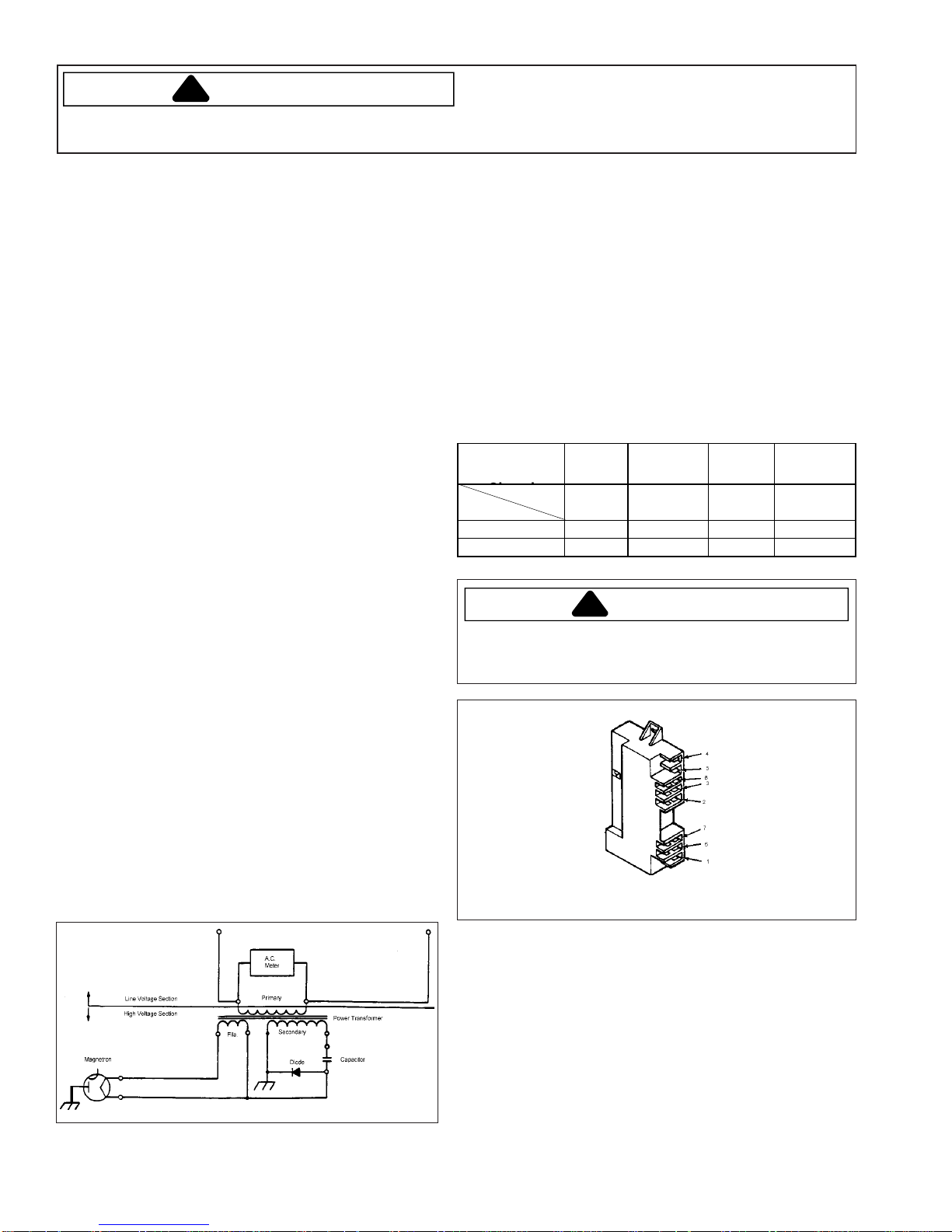
Second Isolation Test
Perform the isolation test when little or no heat is
produced by the oven, but all other operations appear
normal. This test isolates the problem to either the high
voltage section or the line voltage section of the oven.
1. Connect a meter capable of measuring 250volts AC
across the primary of one power transformer .
2. Put the oven into a cook cycle and observe the
voltage reading. Measure the voltage across the
primary of the second power transformer .
Procedure A:
(1line voltage AC) proceed to the high voltage tests in
this section.
Procedure B:
problem is in the line voltage portion of the oven.
If the primary voltages are normal,
If low or no voltage is indicated, the
Interlock switch module tests
The interlock switch module is activated by the door and
door latch assembly. All interlock, monitor and door
sensing functions are performed by this module.
1. Unplug the oven power cord, remove the control panel
assembly, and remove the interlock switch module.
2. Disconnect wire leads from the terminals to be tested
and reinstall the interlock switch module.
3. With an ohmmeter, check continuity between terminals
using the test chart below .
4. If improper indications are given, check the door and
latch for proper activation of switches. If door
activation checks OK, replace Interlock Switch
Module.
X Indicates
Contacts
Termi n al s 8 - 3 6 - 7 1 - 6 4 - 5
Func t ion
Door Open X
Door Closed X X X
Primary
Interlock
Secondary
Interlock
Interlock
Monitor
Door Logic
(Sense)
WARNING
For continued protection against radiation hazard,
replace only with manufactures parts catalog numbered
switch.
Interlock Switch Module
RE220002 Rev. 6 14
!
Test Procedures
!
DANGER
Before touching any oven components or wiring,
capacitor
by shorting across the capacitor terminals with an insulated handle screwdriver.
always
High voltages are present during the cook cycle.
Extreme caution should be observed at all times.
unplug the oven from its power source and
discharge the
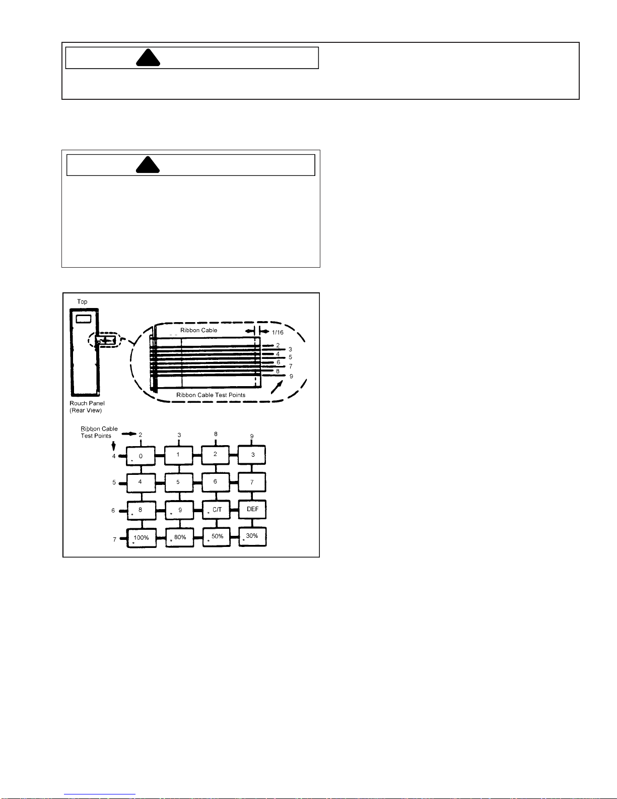
Touch Panel Test
The touch panel operation can be tested with an
ohmmeter on the R x 1 scale.
CAUTION
Over-flexing the ribbon cable will damage the silver
circuit. Pointed test leads cannot be used on ribbon
cable silver circuit or silver circuit will be damaged.
Scratching of the ribbon cable will damage the silver
circuit. Static discharge can damage the controller.
Avoid touching any part of the circuitry on the back of
the controller. Do not bend ribbon cable forward.
1. Unplug the oven power cord and remove the control
panel.
2. Disconnect ribbon cable from circuit board by
applying even pressure to both sides of ribbon cable
and pull outward from ribbon cable connector.
3. Touch ohmmeter test leads to ribbon cable test
points indicated on appropriate test chart.
Resistance should be more than 1 Meg ohms
between ribbon cable test points until a touch panel
pad is depressed. With a touch panel pad
depressed, the resistance between connecting test
points should be less than 100 ohms.
4. If improper indications are given, replace defective
touch panel assembly .
5. Inspect ribbon cable silver circuit; if any silver circuit
is missing from the connector end of the ribbon
cable, evenly trim 1/16" off end of ribbon cable as
shown to assure good electrical connection with
circuit board connector .
6. Apply even pressure to both sides of ribbon cable
while inserting cable into ribbon cable connector.
* These Buttons are not present on VEND-10. VEND10.C has all the
buttons shown except 80%, 50%, and 30% with the 100% button used
as the START button.
15 RE220002 Rev. 6
Test Procedures
!
!
DANGER
Before touching any oven components or wiring,
capacitor
by shorting across the capacitor terminals with an insulated handle screwdriver.
always
High voltages are present during the cook cycle.
Extreme caution should be observed at all times.
unplug the oven from its power source and
discharge the
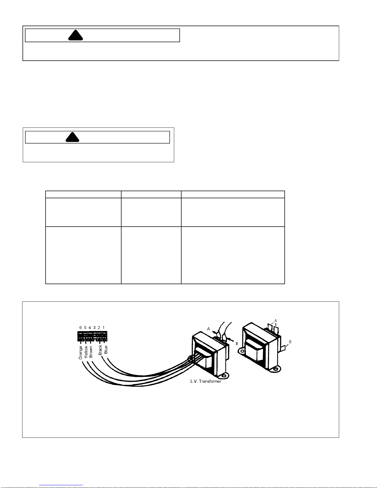
Low Voltage (Controller) Transformer Test
An operational test can be performed to verify proper
operation of the low voltage transformer .
1. Disconnect power to the oven and remove the
control panel assembly .
2. With a voltmeter set to appropriate VAC scale,
perform the following test set-ups, measure and
record the voltage indicated on the meter .
WARNING
Do not touch any oven components or wiring during
oven operation.
TEST SET-UPS TEST POINTS NORMAL VOLTAGE (Approximate)
Attach meter leads to wire harness
test points A - B, apply power to
oven and open oven door.
Disconnect power and remove L.V.
transformer connector attached to
the control circuit board and attach
meter leads into harness side of
connector at test points shown in
chart. Apply power to oven and
open oven door.
A & B
2 (Blue) - 4 (Brown
1 (Black) - 6 (Orange)
5 (Yellow) - 6 (Orange)
Procedure A:
If the proper AC voltages were measured
as shown on the test chart, the low voltage transformer
operation is normal.
Procedure B:
If abnormal reading was measured at test
points 2-4, 1-6, 5-6, as indicated on the test chart but
normal voltage was measured at test points A-B, replace
low voltage transformer. If no voltage was measured at
test points A-B, check wire connections and circuit
diagnosis for other possible causes.
120 VAC on all models except
FS14.EVP.00, FS14EVP.A,
and FS14EVP.B which
is 208 - 230 VAC.
2.6 VAC 23 VAC 46 VAC
FSP-11, VEND10, VEND11
RE220002 Rev. 6 16
A1200S, A1225S, FSP10,
FS14EVP,
FS16EVP

!
Test Procedures
DANGER
Before touching any oven components or wiring,
capacitor
by shorting across the capacitor terminals with an insulated handle screwdriver.
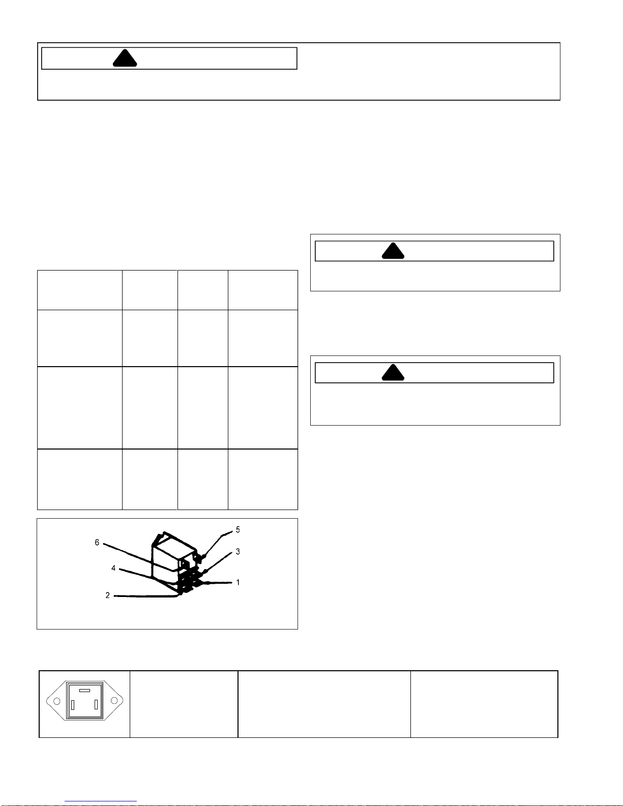
Drive and Holding Relay Test
Drive relay is on .000 and .A models only
1. Disconnect power to oven, and remove but do not
disconnect the control panel assembly. Lower the
back panel to the service position.
2. Perform test set-ups as indicated on the Test Chart
below.
NOTE: Test "Drive" or "Holding" relays one at a time.
Do not disconnect both relays at the same
time.
NOTE: If necessary, remove the component module
panel assembly to connect test leads. Replace
the module assembly prior to performing all
tests except the first two resistance checks.
always
High voltages are present during the cook cycle.
Extreme caution should be observed at all times.
unplug the oven from its power source and
Drive/Holding Relay
discharge the
TEST SET-UP TEST POINTS
1.2.Disconnect power.
Remove harness leads from
relay terminals 1 & 6
1.2.Reconnect harness leads to
terminals 1 & 6.
Remove harness leads from
terminals 2 & 3, and insulate
to prevent electrical short.
1.2.Reconnect power.
Program oven for 15 seconds
and put oven into a COOK
cycle.
1. DRIVE RELAY
Program oven for 15 seconds
and put oven into a COOK
cycle.
NORMAL READINGS
(Approximate)
1 to 6 250 to 350 ohm Replace the relay and retest
2 to 3 Infinite ohms Replace relay and retest
1 to 6 22 Volts DC Replace the controller and
2 to 3 Less than 1 ohm
during cook and for 60
seconds after cook
cycle, then infinite
ohms.
CORRECTIVE ACTION
retest
Replace the relay and retest.
1. HOLDING RELAY
Plug in oven
2 to 3
Less than 1 ohm for
60 seconds, then
inifinte ohms.
17 RE220002 Rev. 6
Replace the relay and retest
Test Procedures
!
!
!
DANGER
Before touching any oven components or wiring,
capacitor
by shorting across the capacitor terminals with an insulated handle screwdriver.
always
High voltages are present during the cook cycle.
Extreme caution should be observed at all times.
unplug the oven from its power source and
discharge the
Holding Relay Test Models
VEND-10 .F, .G, .H, .J, VEND-10, and VEND-11
1. Disconnect power to oven, and remove but do not
disconnect the control panel assembly. Lower the
back panel to the service position.
2. Perform test set-ups as indicated on the Test Chart
below.
NOTE: If necessary, remove the component module
panel assembly to connect test leads. Replace
the module assembly prior to performing all tests
except the first two resistance checks.
TEST SET-UP TERMINAL
TEST
POINT
Di sconnect power.
Remove harness
leads from relay
terminals 5 & 6.
Reconnect harness
leads to terminals 5
& 6. Remove
harness leads from
terminals 1 &3, and
insulate to prevent
electrical short.
Reconnect power.
Program oven for
15 se conds and put
oven into a COOK
cycle.
5 to 6 250 to 350
1 to 3 Infinite
5 to 6 22 VoltsDCReplace the
Holding Relay
NORMAL
READING
ohms
ohms
CORRECTIVE
ACTION
Replace the
relay and
retest.
Replace relay
and retest.
controller and
retest
Triac Module Test
1. Unplug the oven power cord, lower the back panel
and
discharge the capacitor(s).
On FS14, remove
the left magnetron inlet duct.
2.
COMPLETEL Y REMOVE THE HIGH VOLTAGE
LEAD
that connects the capacitor to the transformer
high voltage terminal (marked "HI" or "LO"). On the
FS14EVP also remove the lead between the second
capacitor and high voltage transformer terminal
(marked "HI" or "LO").
WARNING
High voltages are present at the high voltage
secondary terminals during a cook cycle.
3. With a voltmeter capable of measuring 250 VAC,
attach the meter leads to triac terminal MT1 (WHT)
and MT2 (RED). NOTE: Triac harness leads
remain connected.
WARNING
Do not touch any oven components or wiring during
oven operation. Attach meter leads with alligator
clips when making operational tests.
4. Perform the following test; measure and record the
voltage indicated on the meter .
T est Set Up
Set the VEND10 oven to operate on defrost for
one minute. Set the FS10 or FS14 oven to
operate at 50% power level for one minute.
Normal Output Voltage
On VEND10 and FS10 ovens voltage alternates
from 120 V AC to less than 5 VAC. On FS14
ovens alternates from 208/240 volts to less than
5 V AC. FS10 and FS14 alternates approximately
every 6 seconds, VEND10 alternation will vary .
Corrective Action—If abnormal output voltage is
measured.
If controller tests check okay , replace the triac
module and retest.
Triac
MT2
MT1 GATE
This triac is used in
models w ith P130210_M
series
RE220002 Rev. 6 18
Disconnect wires to triac.
Measure re sistance from:
MT1 to MT2
MT1 to Gate
MT2 to Gate
All terminals to ground
Caution - Do not operate oven with
wire to terminal MT2 removed.
Infinite
Approximately 40
Infinite
Infinite
Ω
or more

!
Test Procedures
DANGER
Before touching any oven components or wiring,
capacitor
by shorting across the capacitor terminals with an insulated handle screwdriver.
always
High voltages are present during the cook cycle.
Extreme caution should be observed at all times.
unplug the oven from its power source and
discharge the
Controller Triac Drive Test
NOTE: This test is provided for reference only . The
controller self diagnosis test is normally all that
is required to verify normal controller operation.
1. Unplug the oven power cord, lower the back panel
and
discharge the capacitor(s)
remove the left magnetron inlet duct.
2. Connect voltmeter to triac module terminals marked
GRN and BLU.
3. Apply power to the oven and put the oven into a
cook cycle on full (100%) power setting. The meter
should indicate 1 to 6 volts AC during the cook cycle
and zero volts after completion of the cook cycle.
If abnormal readings were measured, replace the controller and retest.
. On some models,
Cook Relay Test
Models VEND -10.000, .A, .B, .C
1. Unplug the oven power cord and remove the control
panel assembly .
2. Disconnect wiring from cook relay terminals.
3. Connect ohmmeter across cook relay terminals A
and B.
4. Meter should indicate approximately 900 ohms.
Procedure A:
ohms, go on to Step 5.
Procedure B:
replace the cook relay and retest.
5. Connect ohmmeter across relay terminals 11 and
12 as shown below .
6. Press and hold test button on cook relay.
Meter should indicate continuity , (0 ohms). If not,
the cook relay is defective.
If meter indicates approximately 900
If improper indications are given,
7. Release test button.
Meter should indicate infinity . If not, the cook relay is
defective.
8. Connect ohmmeter across relay terminals 13 and 14.
9. Repeat steps 6 and 7.
Cook Relay
Stirrer Motor Test
1. Unplug the oven power cord, lower the back panel,
and
discharge the capacitor(s).
remove the left magnetron inlet duct.
2. Connect a meter capable of measuring 120 volts AC
across the input leads to the stirrer motor .
3. Apply power to oven and open oven door.
Meter should indicate approximately 120 volts AC.
Procedure A:
does not operate, replace the motor. (Check the stirrer
blade to be sure it is not binding on stirrer cover.)
Procedure B:
wiring continuity and system diagnosis.
If meter indicates 120 volts AC but motor
If meter indicates zero volts, check oven
On some models,
Blower Motor Test
1. Unplug the oven power cord, lower the back panel,
discharge the capacitor(s).
2. Check the blower wheel to be sure it is not binding or
frozen.
3. Connect a ohmmeter capable of measuring 120 volts
AC across the input leads to the blower motor.
4. Apply power to oven and open oven door.
Meter should indicate approximately 120 volts AC.
Procedure A:
does not operate, replace the motor.
Procedure B:
wiring continuity and system diagnosis.
If meter indicates 120 volts AC but motor
If meter indicates zero volts, check oven
19 RE220002 Rev. 6

Test Procedures
!
DANGER
Before touching any oven components or wiring,
capacitor
by shorting across the capacitor terminals with an insulated handle screwdriver.
always
High voltages are present during the cook cycle.
Extreme caution should be observed at all times.
unplug the oven from its power source and
discharge the
Auto T ransformer Test
FS-14EVP and FS-16EVP only
1. Unplug oven power cord and remove but do not
disconnect the control panel assembly .
2. With alligator clips, connect a meter capable of
measuring 250 volts AC across the 0 volt and 240 volt
terminals of the auto transformer.
3. Apply power to the oven and open the oven door. A
normal indication should be 220 to 256 volts AC.
Unplug the oven. If voltages are low or high, check
that the voltage adjusting connector is set for the
proper source voltage.
4. Connector meter across the 0 volt and 120 volt
terminals.
5. Apply power to the oven, open the oven door and note
the voltage.
6. Disconnect power to the oven. Connect meter across
the 120 volt and 240 volt terminals.
7. Apply power to the oven, open the oven door, note the
voltage and unplug the oven.
V oltages in steps 5 (terminals 0 and 120 volts) and 7
(terminals 120 and 240 volts) should be within 15 volts of
the same and should be approximately half of the input
voltage measured in step 3. If the voltages in steps 5 and
7 differ by more than 15 volts or are not approximately half
the voltage measured in step 3, replace the auto
transformer and retest.
Thermal Protector Test
Unless an overheating condition exists, a continuity
check across the thermal protector contacts should
indicate a closed circuit (< 1 ohm).
1. Magnetron thermal protector
A. Early production units contained resettable
magnetron thermal protectors.
B. Units produced with the following revision levels
do not reset:
FS10EVP.D
FS14EVP.D
FSP10.C
VEND10.F
2. Cavity thermal protectors will not reset.
DISPLAY
Pin 1
D
E
F
C
G
A
B
Connector
Ribbon
conector
K2
Pin 1
K1
New Controller
208–230 V AC units
FS20 P1302106M
FS 17 P1302105M
120 V AC units
FS11 P1302104M
FSP11 P1302102M
FSP11L W P1302103M
VEND11 P1302101M
Pin Description
A—Line voltage to auto transformer
B—Line voltage to K1 connector
C—Line out from controller to high voltage transformers
D—To triac MT1 pin
E—To triac MT2 pin
F—Gate voltage (.8 V AC) to triac
G—Line in to controller relay contact to H.V .
transformer
K1 Connector
Pin 1 to Pin 3—Line voltage to controller
Pin 6 and Pin 7—V oltage to logic switch
Pin 9—Ground
RE220002 Rev. 6 20
Disassembly Procedures
!
!
!
WARNING
To avoid risk of electrical shock, personal injury, or death,
disconnect power to unit and discharge capacitor(s)
before following any disassembly procedures.
Back Panel Removal/Service Position
1. Place the oven so there is something to support the
back panel when it is lowered.
2. Remove the four screws and lower the back panel to
an approximate horizontal position. The back panel
is now in the service position.
3. To remove back panel:
FS10 and VEND10
A. Disconnect H.V. wires to capacitor and diode.
B. Disconnect panel to chassis ground wire.
FS14
A. Disconnect panel to chassis ground wire.
B. Remove both voltage adjusting connector
assemblies.
CAUTION
To prevent possible electrical shock, this wire must be
reconnected when the back panel is replaced.
C. Power cord.
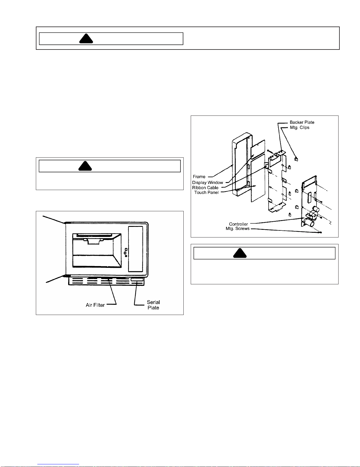
Control Panel Disassembly
1. Remove the control panel assembly.
2. Disconnect the ribbon cable by applying even
pressure to both sides of the ribbon cable and pulling
outward from the ribbon cable connector.
3. Remove six screws and remove controller.
4. Pry off six clips and remove panel and display
window.
Cavity Lamp Replacement
1. Unplug the oven.
2. Remove screw and open the lamp access cover.
3. Replace the cavity lamp. Do not overtighten the
lamp.
Control Panel Assembly Removal
1. Loosen the 3/32" allen-head screw located near the
top of the control panel assembly .
2. Pull the control panel assembly forward and
disconnect the two wire connectors from the control
panel assembly .
CAUTION
Static discharge can damage the controller . A void
touching any part of the circuitry on the back of the
controller .
Installation
1. Visually inspect ribbon cable silver circuit; if any silver
circuit is missing from the connector end of the ribbon
cable, evenly trim 1/16" off end of ribbon cable to
assure good electrical connection with ribbon cable
connector.
2. Apply even pressure to both sides of ribbon cable
while inserting cable into ribbon cable connector.
Visually inspect for proper alignment of silver circuit to
connector tabs.
21 RE220002 Rev. 6
Disassembly Procedures
!
WARNING
To avoid risk of electrical shock, personal injury, or death,
disconnect power to unit and discharge capacitor(s)
before following any disassembly procedures.
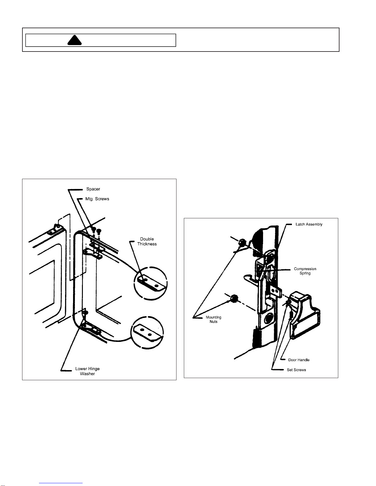
Door Assembly Replacement and
Adjustment
The following door replacement and adjustment
procedures will normally limit radio frequency leakage to
less than 1 mw/cm2 at 5 cm. Although the maximum
allowable leakage is 4 mw/cm2 at 5 cm, effort should be
made to ensure that leakage levels are well below the 4
mw/cm2 at 5 cm.
1. Unplug the power cord.
2. Remove two upper hinge mounting screws.
3. Tilt top of door away from oven and remove door from
oven.
4. Remove lower hinge washer from old door and install
onto new door .
7. Press the door against the cavity faceplate near the
hinges and tighten upper hinge mounting screws.
8. If necessary , adjust the interlock switch module as
described under the INTERLOCK SWITCH MODULE
ADJUSTMENT in this section.
9. Check the oven for proper operation. Check the oven
door operation for radio frequency leakage around
the door with an approved radio frequency measuring
device to ensure less than 4 mw/cm2 emissions at 5
cm. in compliance with U.S. Government
Department of Health and Human Services 21 CFR,
Subchapter J, Performance Standard for Microwave
Ovens.
Door Latch Assembly Replacement
1. Remove door from oven as described in DOOR
REPLACEMENT AND ADJUSTMENT.
2. Disassemble door as described in Door Disassembly.
3. Loosen two set screws and remove door handle.
4. Remove two nuts and remove the door latch
assembly .
5. Install new door into lower hinge, leaving the door 1/2
way open. Place upper hinge and spacer on the top
door pin. Spacer must be installed with the double
thickness toward the oven front and toward the cavity
overhang as shown. Install upper hinge mounting
screws. Leave screws loose.
6. Close oven door.
RE220002 Rev. 6 22
5. Install door latch assembly and reassemble door
using new plastic inner window .
6. Install door on hinges as described under DOOR
REPLACEMENT AND ADJUSTMENT.
7. Check the oven for proper operation. Check for radio
frequency leakage around the door.

Disassembly Procedures
!
WARNING
To avoid risk of electrical shock, personal injury, or death,
disconnect power to unit and discharge capacitor(s)
before following any disassembly procedures.
Interlock Switch Module Adjustment
1. Remove the control panel assembly.
2. Loosen the two screws that mount the interlock
switch module to the cavity assembly .
3. With the oven door closed, align the switch module to
the door hook to provide maximum activation of the
switch actuator .
4. Retighten module mounting screws.
5. Check the oven for proper door closure and switch
operation.
6. Check the oven for proper operation and radio
frequency leakage around the door.
Door Disassembly
1. Remove door from oven as described in DOOR
REPLACEMENT AND ADJUSTMENT in this section.
2. Place door front down on a flat protected surface with
the door handle extending over the edge of the
surface.
3. Peel off the adhesive mounted inner window.
4. Remove door screen mounting screws and remove
door screen.
5. Remove outer window.
6. Remove door filler.
Door Assembly
1. Place door, front down, on a flat protected surface
with the door handle extending over edge of surface.
2. Install outer window.
3. Mount door screen and door filler on outer door.
4. Install door screen mounting screws keeping outer
door as flat as possible.
5. Install adhesive mounted inner window.
6. Install door on hinges as described under DOOR
REPLACEMENT AND ADJUSTMENT in this
section.
7. Check the oven for proper operation. Check for radio
frequency leakage around the door.
Exhaust Transition Duct Replacement
1. Lower the back panel to the service position.
2. Pull the duct toward the oven rear.
3. Rotate the bottom of the duct clockwise to remove.
4. T o replace, insert rib on wrap into slot on top of duct.
Lift up on bottom tabs on duct and rotate bottom of
duct counterclockwise to secure tabs to lower rail on
wrap.
5. Slide duct toward oven front.
23 RE220002 Rev. 6
 Loading...