


HD4060
Table of contents
 Loading...
Operator’s Manual
3000 and 4000
Product Families
International Models
OM4119ENOM4119EN 200805 Printed in USA 200806www.allisontransmission.com

Operator’s
2008 MAY
Manual
OM4119EN
Allison Transmission
INTERNATIONAL MODELS
3000 and 4000 Product Families
Allison 4th Generation Controls
and Model Year 2009 Prognostics
3000 3000 SP
3200 3200 MH 3200 ORS 3200 SP
3500 3500 ORS 3500 SP
3700 3700 SP
4000 4000 MH 4000 ORS 4000 SP
4200 ORS
4430 ORS
4440 ORS
4500 4500 ORS 4500 SP
4600 ORS
4700 4700 OFS 4700 SP
4800 4800 SP
Printed in USA
Copyright © 2008 Allison Transmission, Inc.

NOTES
2

TABLE OF CONTENTS
INTRODUCTION
KEEPING THAT ALLISON ADVANTAGE . . . . . . . . . . . . . . . . . . . . . . . . 7
A BRIEF DESCRIPTION OF THE ALLISON TRANSMISSION . . . . . . . . . . 10
ALLISON 4
TH
GENERATION ELECTRONIC CONTROL SYSTEM . . . . . . . 15
ALLISON 4
TH
GENERATION MODEL YEAR 2009 PROGNOSTICS
FUNCTIONS . . . . . . . . . . . . . . . . . . . . . . . . . . . . . . . . . . . . . . . . . . 16
TORQUE CONVERTER . . . . . . . . . . . . . . . . . . . . . . . . . . . . . . . . . . . 18
PLANETARY GEARS AND CLUTCHES . . . . . . . . . . . . . . . . . . . . . . . . 19
COOLER CIRCUIT . . . . . . . . . . . . . . . . . . . . . . . . . . . . . . . . . . . . . . 19
RETARDER . . . . . . . . . . . . . . . . . . . . . . . . . . . . . . . . . . . . . . . . . . . 19
TRANSFER CASE (DROPBOX) . . . . . . . . . . . . . . . . . . . . . . . . . . . . . . 19
SHIFT SELECTORS
INTRODUCTION . . . . . . . . . . . . . . . . . . . . . . . . . . . . . . . . . . . . . . . 21
DESCRIPTION OF AVAILABLE ALLISON 4
TH
GENERATION
SHIFT SELECTOR TYPES . . . . . . . . . . . . . . . . . . . . . . . . . . . . . . . . . 21
DESCRIPTION OF AVAILABLE ALLISON 4
TH
GENERATION MY09
PROGNOSTICS SHIFT SELECTOR TYPES . . . . . . . . . . . . . . . . . . . . . . 27
RANGE SELECTION . . . . . . . . . . . . . . . . . . . . . . . . . . . . . . . . . . . . . 33
DRIVING TIPS
CHECK TRANS LIGHT . . . . . . . . . . . . . . . . . . . . . . . . . . . . . . . . . . . 39
DIAGNOSTIC CODES OVERVIEW . . . . . . . . . . . . . . . . . . . . . . . . . . . 40
ALLISON 4
TH
GENERATION CONTROLS DIAGNOSTIC CODE DISPLAY
PROCEDURE . . . . . . . . . . . . . . . . . . . . . . . . . . . . . . . . . . . . . . . . . 41
ALLISON 4
TH
GENERATION MY09 PROGNOSTICS DIAGNOSTIC CODE
DISPLAY PROCEDURE . . . . . . . . . . . . . . . . . . . . . . . . . . . . . . . . . . . 43
ACCELERATOR CONTROL . . . . . . . . . . . . . . . . . . . . . . . . . . . . . . . . 46
RANGE SHIFTS AND INHIBITS . . . . . . . . . . . . . . . . . . . . . . . . . . . . . 46
USING THE ENGINE TO SLOW THE VEHICLE . . . . . . . . . . . . . . . . . . . 47
USING THE HYDRAULIC RETARDER . . . . . . . . . . . . . . . . . . . . . . . . . 48
RANGE PRESELECTION . . . . . . . . . . . . . . . . . . . . . . . . . . . . . . . . . . 52
COLD WEATHER STARTS . . . . . . . . . . . . . . . . . . . . . . . . . . . . . . . . . 52
DRIVING ON SNOW OR ICE . . . . . . . . . . . . . . . . . . . . . . . . . . . . . . . 53
ROCKING OUT . . . . . . . . . . . . . . . . . . . . . . . . . . . . . . . . . . . . . . . . 53
HIGH FLUID TEMPERATURE . . . . . . . . . . . . . . . . . . . . . . . . . . . . . . 54
PARKING BRAKE . . . . . . . . . . . . . . . . . . . . . . . . . . . . . . . . . . . . . . 55
TOWING OR PUSHING . . . . . . . . . . . . . . . . . . . . . . . . . . . . . . . . . . . 55
TURNING OFF THE VEHICLE . . . . . . . . . . . . . . . . . . . . . . . . . . . . . . 55
PRIMARY/SECONDARY SHIFT SCHEDULES . . . . . . . . . . . . . . . . . . . . 56
CRUISE CONTROL OPERATION . . . . . . . . . . . . . . . . . . . . . . . . . . . . . 56
3

OPERATING DOWN STEEP GRADES
(REAR-DISCHARGE MIXER) . . . . . . . . . . . . . . . . . . . . . . . . . . . . . . . 57
POWER TAKEOFF OPERATION
ENGINE-DRIVEN POWER TAKEOFF (PTO) . . . . . . . . . . . . . . . . . . . . . 58
CARE AND MAINTENANCE
PERIODIC INSPECTIONS . . . . . . . . . . . . . . . . . . . . . . . . . . . . . . . . . 59
PREVENT MAJOR PROBLEMS . . . . . . . . . . . . . . . . . . . . . . . . . . . . . . 59
IMPORTANCE OF PROPER FLUID LEVEL . . . . . . . . . . . . . . . . . . . . . . 60
ALLISON 4
TH
GENERATION MY09 PROGNOSTICS DISABLED AND SEVEN
SPEED TRANSMISSION FLUID LEVEL CHECK USING ALLISON SHIFT
SELECTORS . . . . . . . . . . . . . . . . . . . . . . . . . . . . . . . . . . . . . . . . . . 60
PROGNOSTICS FUNCTIONALITY FOR MODEL YEAR 2009 . . . . . . . . . . 64
ALLISON 4
TH
GENERATION MY09 PROGNOSTICS ENABLED FLUID LEVEL
CHECK USING ALLISON SHIFT SELECTORS . . . . . . . . . . . . . . . . . . . . 67
FLUID LEVEL CHECK USING DIAGNOSTIC TOOLS . . . . . . . . . . . . . . . 72
MANUAL FLUID CHECK PROCEDURE . . . . . . . . . . . . . . . . . . . . . . . 73
COLD CHECK . . . . . . . . . . . . . . . . . . . . . . . . . . . . . . . . . . . . . . . . . 75
HOT CHECK . . . . . . . . . . . . . . . . . . . . . . . . . . . . . . . . . . . . . . . . . . 76
RECOMMENDED AUTOMATIC TRANSMISSION FLUID AND VISCOSITY
GRADE . . . . . . . . . . . . . . . . . . . . . . . . . . . . . . . . . . . . . . . . . . . . . 76
KEEPING FLUID CLEAN . . . . . . . . . . . . . . . . . . . . . . . . . . . . . . . . . . 78
ALLISON 4
TH
GENERATION AND MY09 PROGNOSTICS DISABLED FLUID
AND INTERNAL FILTER CHANGE INTERVAL RECOMMENDATIONS . . . . 78
ALLISON 4THGENERATION MY09 PROGNOSTICS ENABLED FLUID AND
FILTER CHANGE INTERVAL RECOMMENDATIONS . . . . . . . . . . . . . . . 85
FLUID ANALYSIS . . . . . . . . . . . . . . . . . . . . . . . . . . . . . . . . . . . . . . 87
REFILL TRANSMISSION . . . . . . . . . . . . . . . . . . . . . . . . . . . . . . . . . . 87
DIAGNOSTICS
DIAGNOSTIC CODES . . . . . . . . . . . . . . . . . . . . . . . . . . . . . . . . . . . . 88
CUSTOMER SERVICE
OWNER ASSISTANCE . . . . . . . . . . . . . . . . . . . . . . . . . . . . . . . . . . . 90
SERVICE LITERATURE . . . . . . . . . . . . . . . . . . . . . . . . . . . . . . . . . . . 92
ALLISON TRANSMISSION REGIONAL OFFICES . . . . . . . . . . . . . . . . . . 93
4

TRADEMARK USAGE
The following trademarks are the property of the companies indicated:
• Allison DOC™ is a trademark of General Motors Corporation.
• DEXRON
®
is a registered trademark of the General Motors Corporation.
5
WARNINGS, CAUTIONS, NOTES
IT IS YOUR RESPONSIBILITY to be completely familiar with the warnings
and cautions described in this manual. It is, however, important to understand that
these warnings and cautions are not exhaustive. Allison Transmission could not
possibly know, evaluate, and advise the service trade of all conceivable ways in
which service might be done or of the possible hazardous consequences of each
way. The vehicle manufacturer is responsible for providing information related to
the operation of vehicle systems (including appropriate warnings, cautions, and
notes). Consequently, Allison Transmission has not undertaken any such broad
evaluation. Accordingly, ANYONE WHO USES A SERVICE PROCEDURE
OR TOOL WHICH IS NOT RECOMMENDED BY ALLISON
TRANSMISSION OR THE VEHICLE MANUFACTURER MUST first be
thoroughly satisfied that neither personal safety nor equipment safety will be
jeopardized by the service methods selected.
Proper service and repair is important to the safe, reliable operation of the
equipment. The service procedures recommended by Allison Transmission (or the
vehicle manufacturer) and described in this manual are effective methods for
performing service operations. Some of these service operations require the use of
tools specially designed for the purpose. The special tools should be used when
and as recommended.
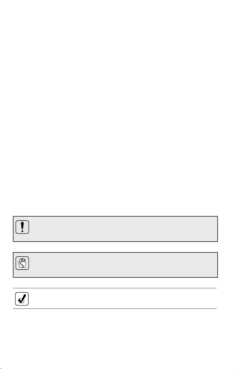
Three types of headings are used in this manual to attract your attention. These
warnings and cautions advise of specific methods or actions that can result in
personal injury, damage to the equipment, or cause the equipment to become
unsafe.
WARNING: A warning is used when an operating procedure, practice,
etc., if not correctly followed, could result in personal injury or loss of
life.
CAUTION: A caution is used when an operating procedure, practice,
etc., if not strictly observed, could result in damage to or destruction of
equipment.
NOTE: A note is used when an operating procedure, practice, etc., is
essential to highlight.
6

INTRODUCTION
KEEPING THAT ALLISON ADVANTAGE
Allison 3000 and 4000 Product Families transmissions are rugged and designed
to provide long, trouble-free service.
This handbook will help the operator gain the maximum benefits from an Allison
transmission-equipped vehicle.
7

Abbreviations
ABS Anti-lock Brake System
DMD Display Mode/Diagnostic
DOC Diagnostic Optimized Connection
DTC Diagnostic Trouble Code
ECU Electronic Control Unit
EMI Electromagnetic Interference
FCC Federal Communications Commission
FM Filter Life Monitor
I/O Input/Output
KOH Potassium Hydroxide
MY09 Model Year 2009
OEM Original Equipment Manufacturer
OLS Oil Level Sensor
OM Oil Life Monitor
PTO Power Takeoff
PWM Pulse Width Modulated
RFI Radio Frequency Interference
RMR Retarder Modulation Request
SP Specialty Series
TAN Total Acid Number
TM Transmission Health Monitor
TPS Throttle Position Sensor
VIM Vehicle Interface Module
8
Your Allison transmission has one of two electronic control systems: Allison 4
Generation Controls, or Allison 4thGeneration MY09 Prognostics Controls. The
current electronic control system being offered is Allison 4
th
Generation MY09
th
Prognostics Controls. The MY09 Prognostics functions of this control system are
explained in Section 3, DRIVING TIPS and Section 5, CARE AND
MAINTENANCE. The operation of the shift selectors is explained in Section 2,
SHIFT SELECTORS.
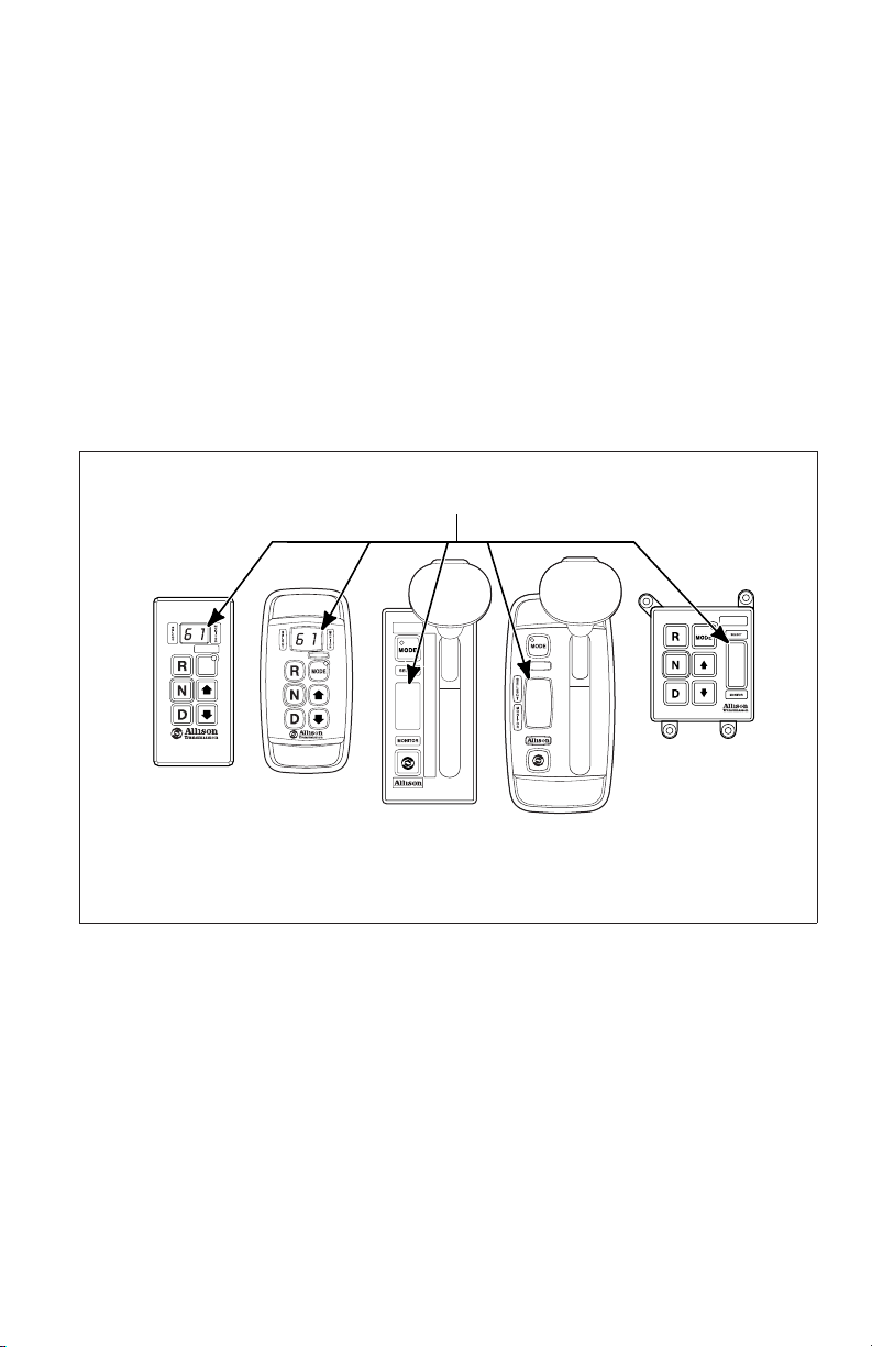
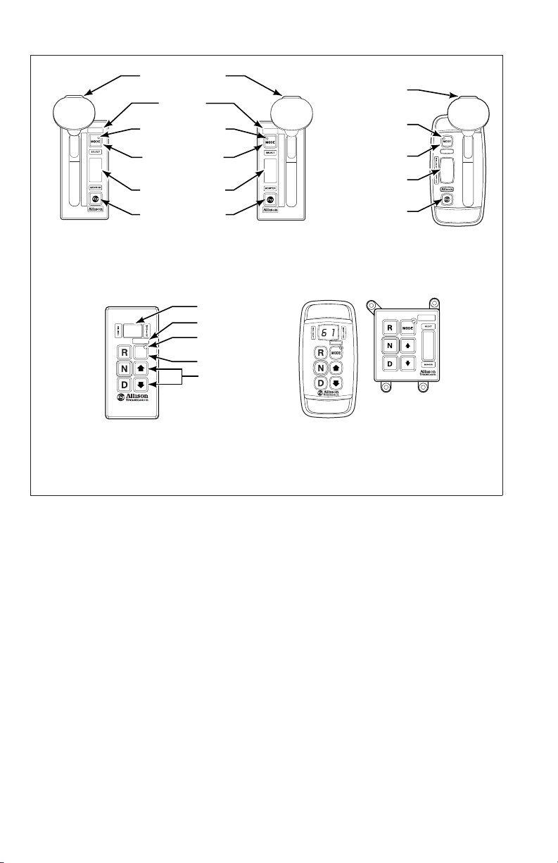
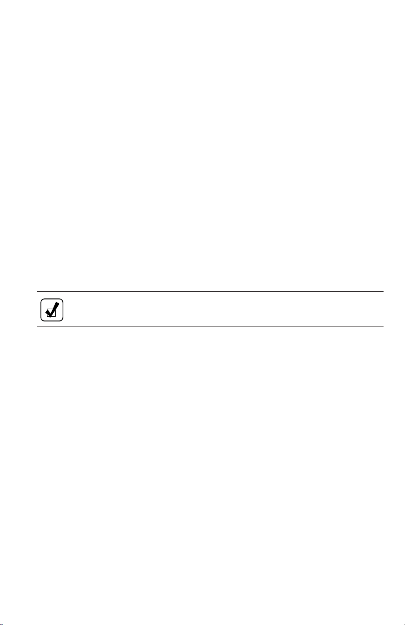
Refer to the shift selectors shown in Figure 1 and Figure 2 to identify which
system is installed in your transmission. The Allison 4
selectors have two LED digital displays (refer to Figure 1). The Allison 4
th
Generation Controls shift
th
Generation MY09 Prognostics Controls shift selectors have two LED digital
displays and a service icon in the form of an open-end wrench between the digital
displays (refer to Figure 2).
DOUBLE DIGIT LED DISPLAY
MODE
R
N
D
6
5
4
1
3
2
1
6
1
ALLISON 4TH GENERATION CONTROLS
6
1
V07344.01.01
Figure 1. Typical Allison 4thGeneration Controls Shift Selectors With
SELECT And MONITOR Digital Displays
9

DOUBLE DIGIT LED DISPLAY
WITH SERVICE ICON
MODE
R
N
D
MODE
MODE
R
N
D
R
N
D
5
4
3
2
1
ALLISON 4TH GENERATION MY09 PROGNOSTICS CONTROLS
V11059.00.01
Figure 2. Typical Allison 4thGeneration MY 09 Prognostics Controls
Shift Selectors With SELECT And MONITOR Digital Displays and
Service Icon (open-end wrench)
A BRIEF DESCRIPTION OF THE ALLISON TRANSMISSION
The Allison transmissions (refer to Figure 3 through Figure 6) described in this
manual include:
th
• Allison 4
• Allison 4
years)
• A torque converter with lockup clutch and torsion damper
• Three planetary gear sets (four for 4700 OFS/SP and 4800 SP)
• Five clutches (six for 4700 OFS/SP and 4800 SP)
Generation Controls
th
Generation MY09 Prognostics (not available on earlier model
An integral retarder is available as an option on all transmissions. A provision to
mount a power takeoff (PTO) is available as an option on all transmissions.
NOTE: Allison electronic controls are designed and manufactured to
comply with all FCC and other guidelines regarding radio frequency
interference/electromagnetic interference (RFI/EMI) for transportation
electronics. Manufacturers, assemblers, and installers of radio-telephone
or two-way communication radios have the sole responsibility to
correctly install and integrate those devices into Allison
transmission-equipped vehicles to customer satisfaction.
10

BREATHER
MAIN-PRESSURE TAP
NOTE: Inch Series Threads
ASSEMBLY PADS
OUTPUT
SPEED
SENSOR
RETARDER
VALVE BODY
CONNECTOR
TACHOGRAPH PROVISION
NOTE: Metric Series Threads
TORQUE CONVERTER
WITH LOCKUP CLUTCH
AND TORSIONAL DAMPER
BREATHER
MAIN-PRESSURE TAP
NOTE: Inch series threads
COOLER PORTS
NOTE: Inch Series Threads
ASSEMBLY PADS
(BOTH SIDES)
OUTPUT
RETARDER
TO RETARDER
ACCUMULATOR
OIL FILL TUBE AND
DIPSTICK
(AVAILABLE ON
BOTH SIDES
)
V07307.02.00
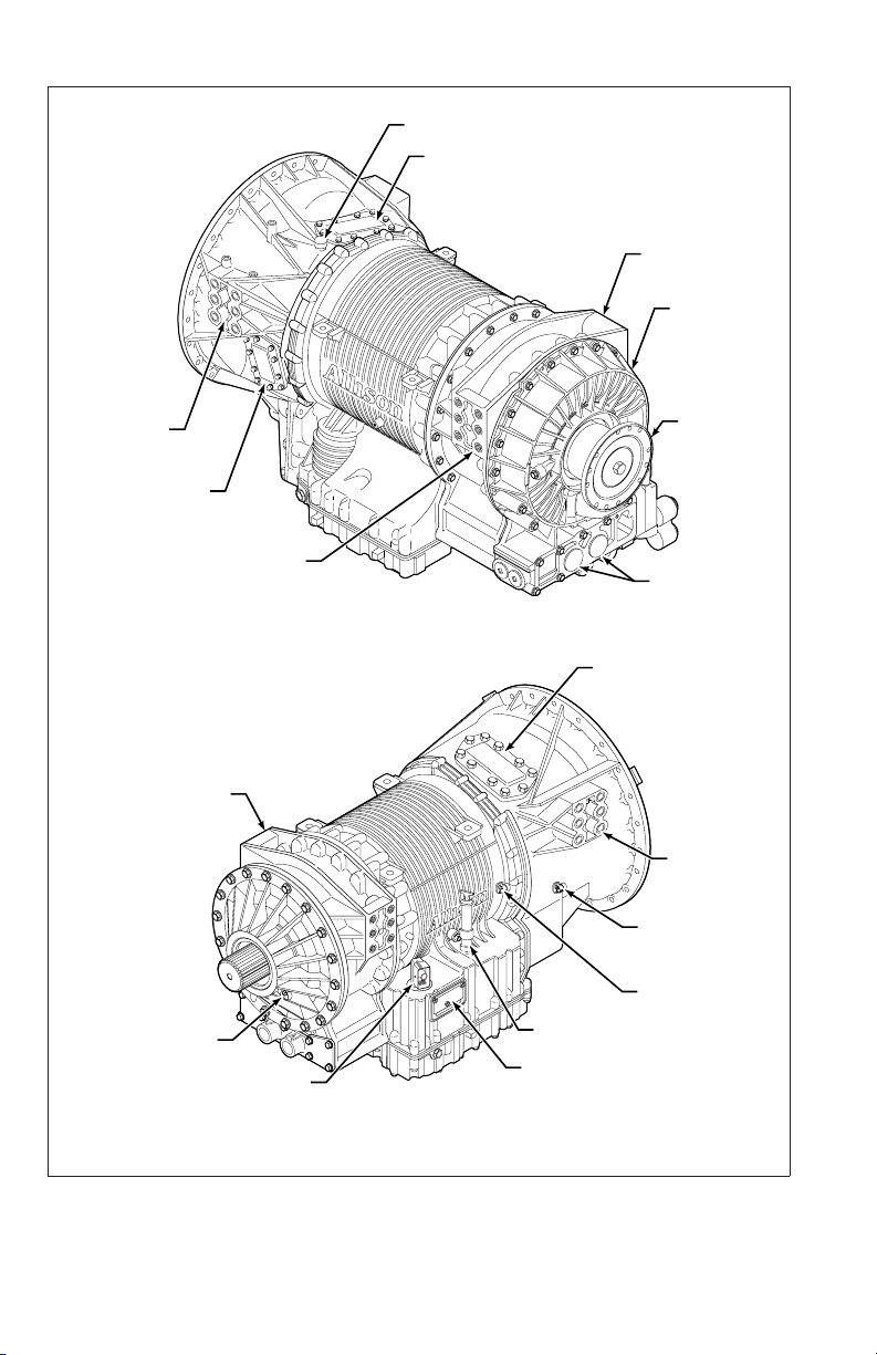
Figure 3. 3200/3500 Model With Retarder
(Allison 4
th
Generation Controls)
11

TRANSFER CASE
FEEDTHROUGH
HARNESS
CONNECTOR
BREATHER
COOLER
PORTS
OIL FILL TUBE
AND DIPSTICK
(AVAILABLE BOTH SIDES)
NAMEPLATE
SCAVENGE PUMP
PTO PROVISION
OIL FILL TUBE
AND DIPSTICK
World Transmission
M
Manufactured By
a
n
u
f
a
c
Division of General Motors CorporationDivision of General Motors Corporation
t
u
r
e
S
d
E
B
R
I
y
A
L
N
Indianapolis, IndianaIndianapolis, Indiana
O
.
XX
X
X
E
C
A
P
S
X
A
N
D
O
R
A
G
E
R
A
U
UAW
X
I
C
E
U
A
L
L
I
W
T
B
U
O
R
M
A
O
L
T
U
I
9
933
A
M
3
D
P
P
E
3
L
T
I
E
N
M
A
U
E
N
A
T
C
R
I
M
R
W
E
M
O
A
R
F
K
O
E
S
R
T
O
N
D
E
O
L
.
N
O
.
XX
X
X
X
XX
X
X
X
X
X
X
RIGHT-FRONT VIEW
ASSEMBLY PADS
(BOTH SIDES)
TRANSFER CASE
LEFT-REAR VIEW
V08626.01.01
Figure 4. 3700 SP With PTO (Allison 4thGeneration Controls)
12

FILL TUBE
RETARDER
TEMPERATURE
CONNECTOR
SOLENOID
CONNECTOR
NAMEPLATE
TURBINE-SPEED
SENSOR
MOUNTING PAD
ENGINE-SPEED SENSOR
RIGHT-FRONT VIEW
PTO PROVISION
(TOP RIGHT POSITION)
TORQUE
CONVERTER
MODULE
BREATHER
MOUNTING PADS
(BOTH SIDES)
PTO PROVISION
MAIN-PRESSURE TAP
Figure 5. 4000/4500 Model With PTO
LEFT-REAR VIEW
(Allison 4
MOUNTING PADS
(BOTH SIDES)
PTO PROVISION
th
Generation Controls)
STANDARD
REAR
COVER
COOLER PORTS
V10695.00.01
13
BREATHER
PTO
PROVISION
C6 ADAPTER
HOUSING
RETARDER
MOUNTING
PAD
PTO PROVISION
MOUNTING PAD
C6 ADAPTER
HOUSING
OUTPUT
SPEED SENSOR
FEEDTHROUGH
HARNESS CONNECTOR
LEFT-REAR VIEW
NAMEPLATE
RIGHT-REAR VIEW
PTO PROVISION
(TOP RIGHT
POSITION)
FILL TUBE
OUTPUT
FLANGE
COOLER
PORTS
MOUNTING
PAD
INPUT
SPEED
SENSOR
TURBINE
SPEED
SENSOR
V08619.01.01
Figure 6. 4700/4800 SP and OFS With PTO And Retarder
(Allison 4
th
Generation Controls)
14

The TCM/ECU is programmed to provide the most suitable operating
characteristics for a specific application. This manual does not attempt to describe
all of the possible combinations. The information contained herein describes only
the operating characteristics most frequently requested by vehicle manufacturers.
ALLISON 4THGENERATION ELECTRONIC CONTROL SYSTEM
Allison 4thGeneration Controls consist of the following major components
connected by an OEM-furnished wiring harness:
• Transmission Control Module (TCM)
• Three speed sensors (refer to Figure 3 through Figure 6):
— Input
— Turbine
— Output
• Remote shift selector
• Control module which includes:
— Solenoids
— Diagnostic pressure switch
— Oil level sensor (standard on the 3000 and 4000 Product Family
transmissions through six-speed, optional on the 4700 OFS/SP and
4800 SP, and not available on 3700 SP)
— Sump temperature sensor
— Valves
— Internal wire harnesses
• Optional Allison Throttle Position Sensor (TPS)
The TCM processes information and then sends signals to actuate specific
solenoids located in the control module. These solenoids control clutch pressures
to provide closed-loop control. The closed-loop control makes “during shift”
adjustments. These adjustments in shift characteristics are based on vehicle
conditions such as grade, load, and engine power. After a shift is completed, the
TCM compares the shift to an “ideal” shift profile in the TCM calibration and
makes adjustments before the next shift of the same kind is made. This is
“adaptive logic” which establishes initial conditions for shifts.
th
The Allison 4
active within the first 30 seconds of the first 24 engine starts or 49 engine starts,
depending upon the component or sensor being detected. Autodetect searches for
the presence of the following transmission components or data inputs.
Generation Control has an “autodetect” feature. Autodetect is
15

Retarder Present, Not Present
Oil Level Sensor (OLS) Present, Not Present
Throttle
* Analog, J1587, J1939
Engine Coolant Temperature Analog, J1587, J1939
* A pulse width modulated (PWM) throttle source is not “autodetected.” This source requires a
unique calibration or can be manually selected using Allison DOC™ For PC–Service Tool.
Even though autodetect has been completed, it can be reset to monitor an
additional group of engine starts. Reset may be necessary if a device known to be
present is not detected or if an autodetectable component or sensor was added
after the initial vehicle build.
Reset is accomplished by using the Allison DOC™ For PC–Service Tool. The
Allison DOC™ For PC–Service Tool may also be used to override autodetect and
manually enter the component or sensor to be recognized by the TCM by
changing appropriate “customer modified constants.”
ALLISON 4THGENERATION MODEL YEAR 2009 PROGNOSTICS FUNCTIONS
Allison Transmission, Inc. has introduced three new diagnostic parameters that are
available only on 3-, 4-, 5-, and 6-speed transmissions for Model Year 2009
(MY09). These new diagnostic parameters will provide indicators of required
maintenance actions and are named “Prognostics” because they predict required
transmission maintenance. These new Prognostics include the following:
• Oil Life Monitor (OM)
• Filter Life Monitor (FM)
• Transmission Health Monitor (TM)
Prognostics are designed to maximize fluid (the terms oil and fluid are used
interchangeably) and filter utilization and provide an early indication of clutch
system concerns so that an inspection may be scheduled before a clutch fails and
causes other transmission damage.
The following items are required to allow MY09 Prognostics:
• Allison approved TES 295 transmission fluid and Allison High Capacity
Filters.
• Transmission with filter life valve body and pressure switch.
• MY09 TCM.
• Filter pressure switch wiring in the OEM wiring harness from the
transmission to the TCM.
• MY09 Allison pushbutton or lever shift selector or an OEM installed shifter
plus a service indicator light or J1939 text message display. The OEM
service indicator light may also be used with a J1939 text messaging
display.
16
Allison MY09 shift selectors contain an integrated service icon in the shape of an
open-end wrench located between the SELECT and MONITOR displays (refer to
DESCRIPTION OF AVAILABLE TYPES in the SHIFT SELECTOR section).
The vehicle manufacturer specifies whether the Allison Prognostics Feature is
made available in the calibration and, if so, whether the Prognostic function is
defaulted ON or OFF for customer use. The transmission calibration can be made
for the vehicle manufacturer (or the customer) so that the prognostics feature is in
one of the following states:
• Available and the function is defaulted ON
• Available but the function is defaulted OFF
NOTE: An Allison service outlet can assist with programming
Prognostics ON at customer expense if Allison requirements are met
prior to Prognostics features being turned ON.
• Not available in the transmission calibration.
NOTE: An Allison service outlet can assist with a transmission
calibration change so that MY09 Prognostics are available at customer
expense if Allison requirements are met prior to TCM recalibration.
The three Prognostics functions are enabled or disabled as a group and cannot be
enabled or disabled individually. The OEM may also specify whether Prognostics
may be reset by the Allison shift selector, J1939 message, or only with the use of
the Allison DOC™ For PC–Service Tool.
CAUTION: Prognostics requires the use of Allison approved
TES 295 fluids and Allison High Capacity Filters if turned ON. If
any other fluids or filters are used, the Prognostics feature MUST BE
turned OFF. Prognostics information will not be accurate with any other
transmission fluids and could result in missed maintenance activities
resulting in transmission damage. If Prognostics functions are not
programmed or are turned OFF, refer to the miles/hours/months fluid
and filter change interval charts in the CARE AND MAINTENANCE
section or visit www.allisontransmission.com, click Service, Fluid/Filter
Change Interval, then Fluids, and read the current revision of Service
Tips 1099 for details.
th
The Allison 4
Generation Controls has an “autodetect” feature. Autodetect is
active within the first 30 seconds of the first 24 engine starts or 49 engine starts,
depending upon the component or sensor being detected. Autodetect searches for
the presence of the following transmission components or data inputs.
17

Retarder Present, Not Present
Oil Level Sensor (OLS) Present, Not Present
Throttle
* Analog, J1587, J1939
Engine Coolant Temperature Analog, J1587, J1939
* A pulse width modulated (PWM) throttle source is not “autodetected.” This source requires a
unique calibration or can be manually selected using Allison DOC™ For PC–Service Tool.
Even though autodetect has been completed, it can be reset to monitor an
additional group of engine starts. Reset may be necessary if a device known to be
present is not detected or if an autodetectable component or sensor was added
after the initial vehicle build.
Reset is accomplished by using the Allison DOC™ For PC–Service Tool. The
Allison DOC™ For PC–Service Tool may also be used to override autodetect and
manually enter the component or sensor to be recognized by the TCM by
changing appropriate “customer modified constants.”
TORQUE CONVERTER
The torque converter consists of the following four elements:
• Pump—input element driven directly by the engine
• Turbine—output element hydraulically driven by the pump
• Stator—reaction (torque multiplying) element
• Lockup Clutch—mechanically couples the pump and turbine when engaged;
controlled by TCM/ECU
When the pump turns faster than the turbine and the stator is stationary, the torque
converter is multiplying torque. When the turbine approaches the speed of the
pump, the stator starts to rotate with the pump and turbine. When this occurs,
torque multiplication stops and the torque converter functions as a fluid coupling.
The lockup clutch is located inside the torque converter and consists of the
following elements:
• Piston and backplate—driven by the engine
• Clutch plate/damper (located between the piston and the
backplate)—splined to the converter turbine
The lockup clutch/torsional damper is engaged and released in response to
electronic signals from the TCM/ECU. Lockup clutch engagement provides a
direct drive from the engine to the transmission input. This eliminates converter
slippage and maximizes fuel economy and vehicle speed. The lockup clutch
releases at lower speeds or when the TCM/ECU detects conditions requiring it to
be released.
18

The torsional damper tries to absorb engine torsional vibration to attempt to
prevent transmitting engine torsional vibration on through to transmission
components (clutches, etc), or items bolted to the transmission (PTO, etc.).
PLANETARY GEARS AND CLUTCHES
A series of three helical, constant mesh planetary gear sets (four for 4700 OFS/SP
and 4800 SP) and shafts provides the mechanical gear ratios and direction of
travel for the vehicle. The planetary gear sets are controlled by five multi-plate
clutches (six for 4700 OFS/SP and 4800 SP) that work in pairs to produce up to
six forward speeds (seven for 4700 OFS/SP and 4800 SP) and one reverse speed.
The clutches are applied and released hydraulically in response to electronic
signals from the TCM/ECU to the appropriate solenoids.
COOLER CIRCUIT
The transmission fluid is cooled by an integral (transmission-mounted) or
remote-mounted oil cooler. Connections to the cooling circuit are located at the
front or rear of the transmission to facilitate installation of remote cooler lines. On
retarder models, only the rear cooler ports may be used. The integral cooler is
mounted on the lower rear portion of the transmission, replacing the remote cooler
manifold. Integral cooler oil ports are internal requiring coolant to be routed to
and from the cooler.
The retarder housing allows the addition of either a remote or integral cooler for
transmission sump fluid in addition to retarder out fluid. A bypass cover is placed
over the sump cooling ports when the provision is not used. The sump cooler
ports are located on the lower right rear face of the retarder housing (refer to
Figure 3 through Figure 6).
RETARDER
The self-contained retarder is at the output of the transmission and consists of a
vaned rotor which rotates in a vaned cavity. The rotor is splined to and driven by
the output shaft. When the retarder is activated, the fluid in the accumulator is
displaced into the retarder cavity. The pressurized fluid in the cavity acting against
the rotating and stationary vanes causes the retarder rotor and output shaft to
reduce speed, slowing the vehicle or limiting speed on a downhill grade. Refer to
USING THE HYDRAULIC RETARDER for additional information.
When the retarder is deactivated, the retarder cavity is evacuated and the
accumulator is recharged with fluid.
TRANSFER CASE (DROPBOX)
A transfer case (dropbox) module is provided for 3700 SP-equipped vehicles
where front and rear wheel drive is desired. The transfer case (refer to Figure 4) is
19

merged with a six-speed close ratio gear train to produce a 7-speed configuration.
One of the two PTO drive provisions actuates a scavenge pump for the transfer
case. A remote-mounted cooler is required for a dropbox unit.
Transfer case design features include helical transfer gears and a self-contained
lubrication oil pump. The transfer gears provide a ratio of 1.2:1. The lubrication
oil pump is driven directly by the output to the drive axles. Since lubrication is
present whenever the drive axle is turning, it is not necessary to disconnect the
drivelines or axles shafts when the vehicle is towed or pushed. A torque
proportioning differential gives a front/rear torque split of 30/70 when the
differential clutch (C7) is not engaged. When the multiplate differential clutch is
engaged, the torque split becomes 50/50. The differential clutch is engaged in
difficult traction situations.
The seventh forward speed in this transmission is the lowest numerical gear ratio
provided and is intended for use in off-road conditions. This range is obtained
when a multi-plate clutch (C6) in the transfer case is applied.
20

SHIFT SELECTORS
INTRODUCTION
Vehicle manufacturers may choose different types of shift selectors for their
vehicles. The shift selector in your Allison-equipped vehicle will be similar to one
of the pushbutton or lever styles (refer to Figure 7 and Figure 8) shown in the
following sections that explain each Allison shift selector.
Allison transmissions can be programmed to have up to six (seven for
4700 OFS/SP and 4800 SP) forward ranges. Shift selector positions should agree
with the programming of the TCM/ECU.
With an Allison-equipped vehicle, it is not necessary to select the right moment to
upshift or downshift during changing road and traffic conditions. The Allison
transmission does it for you. However, knowledge of the shift selector positions,
available ranges, and when to select them make vehicle control and your job even
easier. To reduce wear on service brakes, select lower ranges when descending
long grades (with or without retarder). Refer to the Range Selection table at the
end of this section for related information.
DESCRIPTION OF AVAILABLE ALLISON 4THGENERATION SHIFT SELECTOR TYPES
NOTE: This section is for Allison 4thGeneration Controls, Model Year
2009 Prognostics DISABLED, and seven-speed transmissions which
don’t have Prognostics.
21
HOLD OVERRIDE
1
2
3
6
4
5
1
D
N
R
DIAGNOSTIC BUTTON
SIX-SPEED,
LEFT-HAND
LEVER SELECTOR
WITH REVERSE
TO REAR
7 1
MODE
BUTTON
MODE ID
MODE INDICATOR
(LED)
MODE BUTTON
DIGITAL DISPLAY
DISPLAY MODE
DIGITAL DISPLAY*
MODE ID
MODE
INDICATOR (LED)
MODE BUTTON
Push simultaneously
to enter diagnostic
mode and fluid
level check
R
N
D
6
7
5
4
1
3
*
2
1
SEVEN-SPEED,
RIGHT-HAND
LEVER SELECTOR
WITH REVERSE
TO FRONT
HOLD OVERRIDE
BUTTON
MODE INDICATOR
DIGITAL DISPLAY*
DIAGNOSTIC BUTTON
(LED)
MODE BUTTON
DISPLAY MODE
CONTOURED
6
1
PUSHBUTTON SELECTORS
NOTE:
The first number displayed in the digital display is the highest forward range available and
*
second number is range attained in selected position.
Visually confirm that the range selected was attained. If display is flashing, shift is inhibited.
6
1
BEZEL
V10694.00.01
Figure 7. Typical Allison 4thGeneration Controls Shift Selectors
LEVER SHIFT SELECTOR.
th
General Description. The Allison 4
Generation lever shift selector (refer to
Figure 7) is an electromechanical control. Typical lever positions are:
• R (Reverse)
• N (Neutral)
• D (Drive)
• Some number of lower forward range positions
Allison transmissions can be programmed to have up to six (seven for
4700 OFS/SP and 4800 SP) forward ranges. Shift selector positions should agree
with the programming of the TCM.
The lever shift selector includes the following:
• HOLD OVERRIDE button
• MODE button
22
• Digital display
• DISPLAY MODE/DIAGNOSTIC button
Hold Override Button. The lever shift selector has three locked positions to
prevent accidentally selecting R (Reverse), N (Neutral), or D (Drive). Select
R (Reverse), N (Neutral), or D (Drive) by pressing the HOLD OVERRIDE
button and moving the lever to the desired position. Once D (Drive) is selected,
lower forward range positions may be selected without pressing the
HOLD OVERRIDE button.
MODE Button. The MODE button can allow the driver to enable a secondary
shift schedule, PTO enable, or other special functions that have been programmed
into the TCM unit at the request of the OEM. For example, a vehicle OEM may
have provided a secondary shift schedule for improved fuel economy. The name
of the special function (ECONOMY) appears on the MODE ID label adjacent to
the MODE button. Pressing the MODE button activates the ECONOMY shift
schedule and illuminates the MODE INDICATOR LED.
When the Diagnostic Display Mode has been entered, the MODE button is used
to view and toggle through diagnostic code information. The code displayed is
active if the MODE INDICATOR LED is illuminated.
NOTE: Visually observe the digital display whenever the lever is
moved. N should appear in the digital display if N is selected.
Digital Display. Allison 4thGeneration Controls contain two digital displays,
SELECT and MONITOR. During normal operation, if D (Drive) is selected, the
SELECT digital display shows the highest forward range attainable for the shift
schedule in use. The MONITOR digital display shows the lowest available
forward range.
Limited operation is indicated by the digital display as follows:
• All digital display segments are illuminated during initialization. If after
10 seconds communication is not established with the TCM, both digital
displays show
• When both digital displays show
\
/\(cateyes).
\
/\(cateyes), a selector-related fault code
has been logged.
• When the SELECT display shows R or D has been requested and the
display is flashing the selected range, then the selected range has not been
attained due to an inhibit function. Refer to RANGE SHIFTS AND
INHIBITS in the DRIVING TIPS section.
• Inhibited range, shown by a flashing SELECT digital display, is not an
indication that there is a transmission condition or problem, nor does it
indicate that a DTC has set. An inhibit means there is a vehicle or engine
condition that won’t allow range selection or direction change such as:
23

— Too high idle speed in N to allow R or D
— Too high a throttle signal in N to allow R or D
— Too high of an output speed in N to allow R or D
— An active vehicle function or I/O function is operating which inhibits
range.
CAUTION: The transmission will not shift into range from N if a
CHECK TRANS code is active. If a CHECK TRANS code is active,
move vehicle to a safe location before turning off the engine.
Conditions which illuminate the CHECK TRANS light disable the shift selector.
The SELECT display is blank and the MONITOR display shows the range
actually attained. For a detailed explanation, refer to the CHECK TRANS LIGHT
paragraph in the DRIVING TIPS section.
Once D (Drive) is attained, the transmission will shift into the lowest forward
range programmed for the D (Drive) position, usually first-range.
Display Mode/Diagnostic Button. The DISPLAY MODE/DIAGNOSTIC button
allows access to fluid level information and diagnostic code information.
• Move the shift lever to N and apply the parking brakes.
• Press the DISPLAY MODE/DIAGNOSTIC (DMD) button once to access
oil level information (if an OLS is installed).
• Press the DMD again to access the diagnostic code information.
• Press the MODE button to view subsequent code positions d2 through d5.
• To exit the diagnostic code mode, move the shift lever to another position.
PUSHBUTTON SHIFT SELECTOR.
General Description. The pushbutton shift selector (refer to Figure 7) has the
following components:
• R (Reverse)—Press this button to select Reverse
• N (Neutral)—Press this button to select Neutral
• D (Drive)—Press this button to select Drive. The highest forward range
available will appear in the digital display window. The transmission will
start out in the lowest available forward range and advance automatically to
the highest range.
• ↑ (Up) Arrow—Press the ↑ (Up) Arrow when in D (Drive) to request the
next higher range. Continually pressing the ↑ (Up) Arrow will request the
highest range available.
• ↓ (Down) Arrow—Press the ↓ (Down) Arrow when in D (Drive) to
request the next lower range. Continually pressing the ↓ (Down) Arrow
will request the lowest range available.
24

• MODE Button—The MODE button can allow the driver to enable a
secondary shift schedule, PTO enable, or other special functions that have
been programmed into the TCM at the request of the OEM. For example, a
vehicle OEM may have provided a secondary shift schedule for improved
fuel economy. The name of the special function (ECONOMY) appears on
the MODE ID label adjacent to the MODE button. Pressing the MODE
button activates the ECONOMY shift schedule and illuminates the MODE
INDICATOR LED. When the Diagnostic Display Mode has been entered,
the MODE button is used to view and toggle through diagnostic code
information. The code displayed is active if the MODE INDICATOR LED
is illuminated.
th
Digital Display. Allison 4
Generation Controls contain two digital displays,
SELECT and MONITOR. During normal operation, if D (Drive) is selected, the
SELECT display shows the highest forward range attainable for the shift schedule
in use. The MONITOR display shows the lowest available forward range.
Limited operation is indicated by the digital display as follows:
• All digital display segments are illuminated during initialization. If after
10 seconds communication is not established with the TCM, both digital
displays show
• When both digital displays show
\
/\(cateyes).
\
/\(cateyes), a selector-related fault code
has been logged.
• When the SELECT display shows R or D has been requested and the
display is flashing the selected range, then the selected range has not been
attained due to an inhibit function. Refer to RANGE SHIFTS AND
INHIBITS in the DRIVING TIPS section.
• Inhibited range, shown by a flashing SELECT digital display, is not an
indication that there is a transmission condition or problem, nor does it
indicate that a DTC has set. An inhibit means there is a vehicle or engine
condition that won’t allow range selection or direction change such as:
— Too high idle speed in N to allow R or D
— Too high a throttle signal in N to allow R or D
— Too high of an output speed in N to allow R or D
— An active vehicle function or I/O function is operating which inhibits
range.
CAUTION: The transmission will not shift into range from N if a
CHECK TRANS code is active. If a CHECK TRANS code is active,
move vehicle to a safe location before turning off the engine.
Conditions which illuminate the CHECK TRANS light disable the shift selector.
The SELECT display is blank and the MONITOR display shows the range
actually attained. For a detailed explanation, refer to the CHECK TRANS LIGHT
paragraph in the DRIVING TIPS section.
25

Once D (Drive) is attained, the transmission will shift into the lowest forward
range programmed for the D (Drive) position, usually first-range.
NOTE: The oil level sensor (OLS) is standard on 3000 and 4000
Product Families transmissions (optional on the 4700 OFS/SP, 4800 SP,
not available on 3700 SP). Fluid level information is displayed by
simultaneously pressing the ↑ (Up) Arrow and ↓ (Down) Arrow
buttons. Simultaneously press both buttons again to obtain diagnostic
code information.
To display stored codes, do the following:
• Select N and apply the parking brakes.
• Simultaneously press the ↑ (Up) Arrow and ↓ (Down) Arrow buttons once
to access oil level information (if an OLS is installed).
• Simultaneously press the ↑ (Up) Arrow and ↓ (Down) Arrow buttons
again to access diagnostic codes.
• Press the MODE button to display the next code. Repeat for code positions
d3 through d5.
• Press N (Neutral) to exit the diagnostic code mode.
Refer to the CARE AND MAINTENANCE section, FLUID LEVEL CHECK
USING PUSHBUTTON OR LEVER SHIFT SELECTOR, for more information
about fluid level data. Refer to the DRIVING TIPS section, DIAGNOSTIC
CODES DISPLAY PROCEDURE, for more information about diagnostic codes
and display procedure.
26

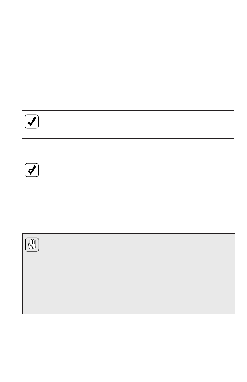
DESCRIPTION OF AVAILABLE ALLISON 4THGENERATION MY09 PROGNOSTICS SHIFT SELECTOR TYPES
NOTE: This section is for Allison 4thGeneration Model Year 2009
(MY09) Prognostics ENABLED. Refer to the previous section for
MY09 Prognostics DISABLED and seven-speed transmissions which
don’t have Prognostics.
LEVER SHIFT SELECTOR.
General Description. The Allison lever shift selector (refer to Figure 8) is an
electromechanical control. Typical lever positions are:
• R (Reverse)
• N (Neutral)
• D (Drive)
• Some number of lower forward range positions
Allison transmissions can be programmed to have up to six (seven for
4700 OFS/SP and 4800 SP) forward ranges. Shift selector positions should agree
with the programming of the TCM.
The lever shift selector includes the following:
• HOLD OVERRIDE button
• MODE button
• DISPLAY MODE/DIAGNOSTIC button
• SELECT and MONITOR digital displays and service icon
Hold Override Button. The lever shift selector has three locked positions to
prevent accidentally selecting R (Reverse), N (Neutral), or D (Drive). Select
R (Reverse), N (Neutral), or D (Drive) by pressing the HOLD OVERRIDE
button and moving the lever to the desired position. Once D (Drive) is selected,
lower forward range positions may be selected without pressing the
HOLD OVERRIDE button.
MODE Button. The MODE button can allow the driver to enable a secondary
shift schedule, PTO enable, or other special functions that have been programmed
into the TCM unit at the request of the OEM. For example, a vehicle OEM may
have provided a secondary shift schedule for improved fuel economy. The name
of the special function (ECONOMY) appears on the MODE ID label adjacent to
the MODE button. Pressing the MODE button activates the ECONOMY shift
schedule and illuminates the MODE INDICATOR LED.
When the Diagnostic Display Mode has been entered, the MODE button is used
to view and toggle through diagnostic code information. The code displayed is
active if the MODE INDICATOR LED is illuminated.
27
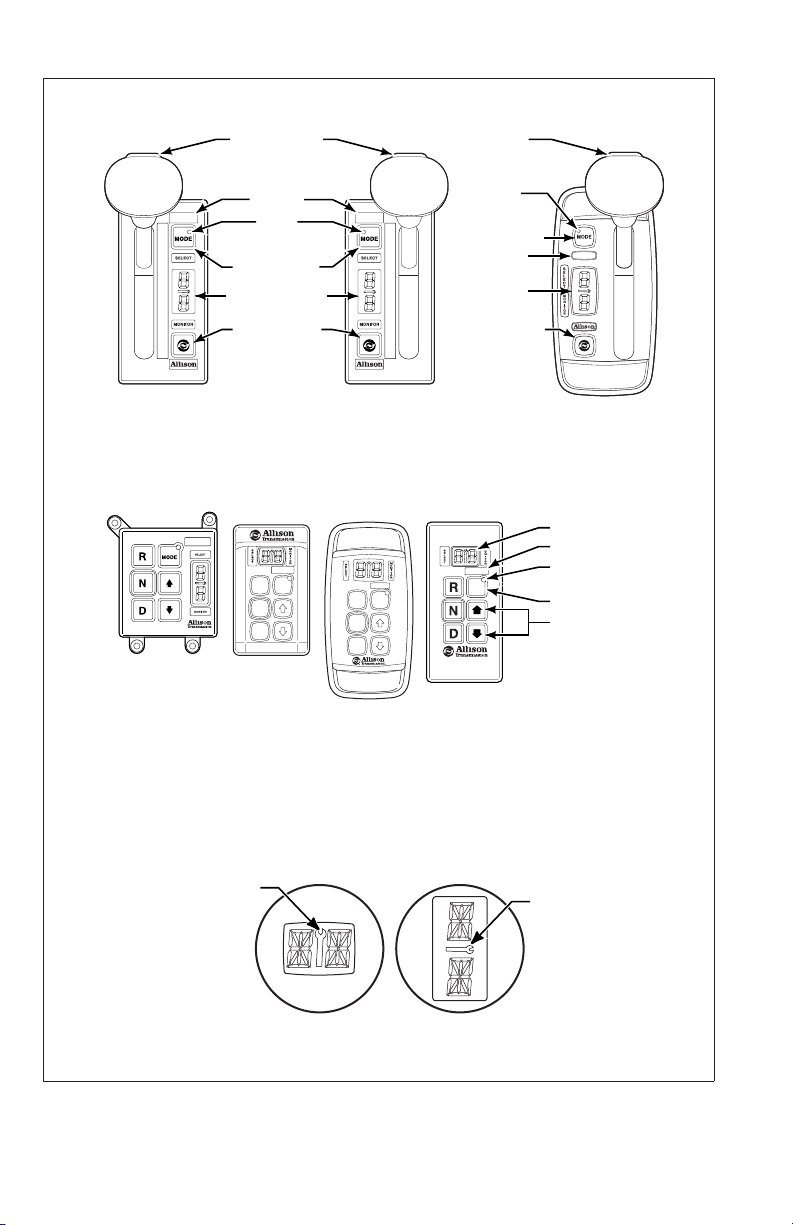
HOLD OVERRIDE
BUTTON
HOLD OVERRIDE
BUTTON
1
2
3
4
5
D
N
R
SIX-SPEED,
LEFT-HAND
LEVER SELECTOR
MODE ID
MODE
INDICATOR
(LED)
MODE BUTTON
DIGITAL DISPLAY
DISPLAY MODE
DIAGNOSTIC
BUTTON
*
SEVEN-SPEED,
RIGHT-HAND
LEVER SELECTOR
MODE
R
N
D
MODE
R
N
D
PUSHBUTTON SELECTORS
MODE
INDICATOR
(LED)
R
N
D
6
5
4
3
2
1
MODE BUTTON
MODE ID
DIGITAL
DISPLAY
*
DISPLAY MODE
DIAGNOSTIC
BUTTON
CONTOURED
BEZEL
DIGITAL DISPLAY
MODE ID
MODE
MODE
INDICATOR (LED)
MODE BUTTON
Push simultaneously
to enter diagnostic
mode and fluid
level check
*
*NOTE:
The first number displayed in the digital display is the highest forward range available and second
number is range attained in selected position.
Visually confirm that the range selected was attained. If display is flashing, shift is inhibited.
SERVICE ICON
Location of service icon on vertical and horizontal digital display
SERVICE ICON
V11058.00.00
Figure 8. Typical Allison 4thGeneration MY09 Prognostics Shift
Selectors
28
Loading...