


Troubleshooting Manual
5000, 6000, 8000, 9000 Series
Off-Highway Transmissions
Commercial Electronic Controls 2 (CEC2)
TS3353EN
TS 3353EN
Troubleshooting
Manual
Allison Off-Highway
5000, 6000, 8000, 9000 Series Transmissions
Commercial Electronic Controls 2 (CEC 2)
M 5610A, M 5610AR
S 5610H, S 5610NR, S 5610M
M 6610A, M 6610AR
S 6610H, S 6610HR, S 6610M
M 8610A, M 8610AR
S 8610H, S 8610HR, S 8610M, S 8610MR
M 9610A, M 9610AR
S 9610A, S 9610AR, S 9610M, S 9610MR
S 9810A, S 9810AR, S 9810H, S 9810HR, S 9810M, S 9810MR
2000 SEPTEMBER
Division of General Motors Corporation
P.O. Box 894 Indianapolis, Indiana 46206-0894
www.allisontransmission.com
Printed in the U.S.A. |
Copyright © 2000 General Motors Corp. |

COMMERCIAL ELECTRONIC CONTROLS 2 (CEC 2) TROUBLESHOOTING MANUAL
FOREWORD — How to Use This Manual
This manual provides troubleshooting information for Allison Transmission Division, 5000, 6000, 8000, and 9000 Series Off-Highway Transmissions which have CEC 2. Service Manuals SM1866EN (5000, 6000), SM1228EN (8000) and SM1833EN (9000), plus Parts Catalogs PC1860EN (5000, 6000), PC1249EN (8000) and PC1830EN (9000) may be used in conjunction with this manual.
This manual includes:
•Description of the CEC 2 system.
•Description of the electronic control system components.
•Description of diagnostic codes, system responses to faults, and troubleshooting.
•Wire, terminal, and connector repair information.
Specific instructions for using many of the available or required service tools and equipment are not included in this manual. The service tool manufacturer will furnish instructions for using the tools or equipment.
Additional information may be published from time to time in Service Information Letters (SIL) and will be included in future revisions of this and other manuals. Please use these SILs to obtain up-to-date information concerning Allison Transmission products.
This publication is revised periodically to include improvements, new models, special tools, and procedures. A revision is indicated by a letter suffix added to the publication number. Check with your Allison Transmission service outlet for the currently applicable publication. Additional copies of this publication may be purchased from authorized Allison Transmission service outlets or from:
SGI, Inc.
Attn: Allison Literature Fulfillment Desk
8350 Allison Avenue
Indianapolis, IN 46268
TOLL FREE: 888-666-5799
INTERNATIONAL: 317-471-4995
Take time to review the Table of Contents and the manual. Reviewing the Table of Contents will aid you in quickly locating information.
NOTE: Allison Transmission is providing for service of wiring harnesses and wiring harness components as follows:
•Repair parts for the internal wiring harness and for wiring harness components attached to the shift selector will be available through the Allison Transmission Parts Distribution Center (PDC). Use the P/N from your appropriate parts catalog or from Appendix E in this manual. Allison Transmission is responsible for warranty on these parts.
•Repair parts for the external harnesses and external harness components must be obtained from St. Clair Technologies Inc. (SCTI). SCTI provides parts to any Allison customer or OEM and is responsible for warranty on these parts. SCTI recognizes ATD, manufacturers, and SCTI part numbers. SCTI provides a technical HELPLINE at 519-627-1673 (Wallaceburg). SCTI will have parts catalogs available. The SCTI addresses and phone numbers for parts outlets are:
St. Clair Technologies, Inc. |
St. Clair Technologies, Inc. |
St. Clair Technologies, Inc. |
1050 Old Glass Road |
1111 Mikesell Street |
c/o Mequilas Tetakawi |
Wallaceburg, Ontario, N8A 3T2 |
Charlotte, MI 48813 |
Carr. Internationale KM 1969 |
Phone: (519) 627-1673 |
Phone: (517) 541-8166 |
Guadalajara – Nogales, KM2 |
Fax: (519) 627-4227 |
Fax: (517) 541-8167 |
Empalme, Sonora, Mexico |
|
|
Phone: 011-52-622-34661 |
|
|
Fax: 011-52-622-34662 |
•St. Clair Technologies, Inc. stocks a CEC 2 external harness repair kit, P/N 29532362, as a source for some external harness repair parts. SCTI is the source for external harness repair parts.
ii |
Copyright © 2000 General Motors Corp. |

COMMERCIAL ELECTRONIC CONTROLS 2 (CEC 2) TROUBLESHOOTING MANUAL
IMPORTANT SAFETY NOTICE
IT IS YOUR RESPONSIBILITY to be completely familiar with the warnings and cautions used in this manual. These warnings and cautions advise against using specific service procedures that can result in personal injury, equipment damage, or cause the equipment to become unsafe. These warnings and cautions are not exhaustive. Allison Transmission could not possibly know, evaluate, or advise the service trade of all conceivable procedures by which service might be performed or of the possible hazardous consequences of each procedure. Consequently, Allison Transmission has not undertaken any such broad evaluation. Accordingly, ANYONE WHO USES A SERVICE PROCEDURE OR TOOL WHICH IS NOT RECOMMENDED BY ALLISON TRANSMISSION MUST first be thoroughly satisfied
that neither personal safety nor equipment safety will be jeopardized by the service procedures used.
Also, be sure to review and observe WARNINGS, CAUTIONS, and NOTES provided by the vehicle manufacturer and/or body builder before servicing the Allison transmission in that vehicle.
Proper service and repair is important to the safe and reliable operation of the equipment. The service procedures recommended by Allison Transmission and described in this manual are effective methods for performing troubleshooting operations. Some procedures require using specially designed tools. Use special tools when and in the manner recommended.
The WARNINGS, CAUTIONS, and NOTES in this manual apply only to the Allison transmission and not to other vehicle systems which may interact with the transmission. Be sure to review and observe any vehicle system information provided by the vehicle manufacturer and/or body builder at all times the Allison transmission is being serviced.
WARNINGS, CAUTIONS, AND NOTES
Three types of headings are used in this manual to attract your attention:
WARNING! Is used when an operating procedure, practice, etc., which, if not correctly followed, could result in injury or loss of life.
CAUTION:
Is used when an operating procedure, practice, etc., which, if not strictly observed, could result in damage to or destruction of equipment.
NOTE: Is used when an operating procedure, practice, etc., is essential to highlight.
Copyright © 2000 General Motors Corp. |
iii |

COMMERCIAL ELECTRONIC CONTROLS 2 (CEC 2) TROUBLESHOOTING MANUAL
INTRODUCTION
TRADEMARKS USED IN THIS MANUAL
The following trademarks are the property of the companies indicated:
•LPS® Cleaner is a registered trademark of LPS Laboratories.
•Loctite® is a registered trademark of the Loctite Corporation.
•Teflon® is a registered trademark of the DuPont Corporation.
•Pro-Link® is a registered trademark of MicroProcessor Systems, Inc.
iv |
Copyright © 2000 General Motors Corp. |

COMMERCIAL ELECTRONIC CONTROLS 2 (CEC 2) TROUBLESHOOTING MANUAL
TABLE OF CONTENTS
Page
Foreword. . . . . . . . . . . . . . . . . . . . . . . . . . . . . . . . . . . . . . . . . . . . . . . . . . . . . . . . . . . . . . . . . . . . . . . . . . . . . ii
SAFETY INFORMATION
Important Safety Notice . . . . . . . . . . . . . . . . . . . . . . . . . . . . . . . . . . . . . . . . . . . . . . . . . . . . . . . . . . . iii Warnings, Cautions, and Notes . . . . . . . . . . . . . . . . . . . . . . . . . . . . . . . . . . . . . . . . . . . . . . . . . . . . . . iii Trademarks Used in This Manual . . . . . . . . . . . . . . . . . . . . . . . . . . . . . . . . . . . . . . . . . . . . . . . . . . . . .iv
SECTION 1. GENERAL DESCRIPTION
1–1. TRANSMISSION . . . . . . . . . . . . . . . . . . . . . . . . . . . . . . . . . . . . . . . . . . . . . . . . . . . . . . . . . . . . . . . 1–1 1–2. ELECTRONIC CONTROL UNIT (ECU) . . . . . . . . . . . . . . . . . . . . . . . . . . . . . . . . . . . . . . . . . . . . 1–3 1–3. SHIFT SELECTOR . . . . . . . . . . . . . . . . . . . . . . . . . . . . . . . . . . . . . . . . . . . . . . . . . . . . . . . . . . . . . 1–3 A. Pushbutton Shift Selector . . . . . . . . . . . . . . . . . . . . . . . . . . . . . . . . . . . . . . . . . . . . . . . . . . . . . . 1–3 B. Lever Shift Selector . . . . . . . . . . . . . . . . . . . . . . . . . . . . . . . . . . . . . . . . . . . . . . . . . . . . . . . . . . . 1–4
1–4. THROTTLE POSITION SENSOR. . . . . . . . . . . . . . . . . . . . . . . . . . . . . . . . . . . . . . . . . . . . . . . . . . 1–4 1–5. SPEED SENSORS . . . . . . . . . . . . . . . . . . . . . . . . . . . . . . . . . . . . . . . . . . . . . . . . . . . . . . . . . . . . . . 1–5 1–6. ELECTRO-HYDRAULIC VALVE COMPONENTS. . . . . . . . . . . . . . . . . . . . . . . . . . . . . . . . . . . . 1–5 1–7. WIRING HARNESSES . . . . . . . . . . . . . . . . . . . . . . . . . . . . . . . . . . . . . . . . . . . . . . . . . . . . . . . . . . 1–6 A. External Wiring Harness . . . . . . . . . . . . . . . . . . . . . . . . . . . . . . . . . . . . . . . . . . . . . . . . . . . . . . . 1–6 B. Internal Wiring Harnesses . . . . . . . . . . . . . . . . . . . . . . . . . . . . . . . . . . . . . . . . . . . . . . . . . . . . . . 1–8
1–8. VEHICLE INTERFACE MODULE . . . . . . . . . . . . . . . . . . . . . . . . . . . . . . . . . . . . . . . . . . . . . . . . . 1–9 1–9. AUTODETECT FEATURE . . . . . . . . . . . . . . . . . . . . . . . . . . . . . . . . . . . . . . . . . . . . . . . . . . . . . . . 1–9
SECTION 2. DEFINITIONS AND ABBREVIATIONS
2–1. CHECK TRANS LIGHT . . . . . . . . . . . . . . . . . . . . . . . . . . . . . . . . . . . . . . . . . . . . . . . . . . . . . . . . . 2–1 2–2. DIAGNOSTIC DATA READER . . . . . . . . . . . . . . . . . . . . . . . . . . . . . . . . . . . . . . . . . . . . . . . . . . . 2–1 2–3. ABBREVIATIONS . . . . . . . . . . . . . . . . . . . . . . . . . . . . . . . . . . . . . . . . . . . . . . . . . . . . . . . . . . . . . . 2–2
SECTION 3. BASIC KNOWLEDGE
3–1. BASIC KNOWLEDGE REQUIRED . . . . . . . . . . . . . . . . . . . . . . . . . . . . . . . . . . . . . . . . . . . . . . . . 3–1 3–2. USING THE TROUBLESHOOTING MANUAL . . . . . . . . . . . . . . . . . . . . . . . . . . . . . . . . . . . . . . 3–2 3–3. SYSTEM OVERVIEW . . . . . . . . . . . . . . . . . . . . . . . . . . . . . . . . . . . . . . . . . . . . . . . . . . . . . . . . . . . 3–2 3–4. IMPORTANT INFORMATION IN THE TROUBLESHOOTING PROCESS . . . . . . . . . . . . . . . . 3–2 3–5. BEGINNING THE TROUBLESHOOTING PROCESS . . . . . . . . . . . . . . . . . . . . . . . . . . . . . . . . . 3–3
SECTION 4. WIRE CHECK PROCEDURES
4–1. CHECKING OPENS, SHORTS BETWEEN WIRES, AND SHORTS-TO-GROUND . . . . . . . . . 4–1
4–2. CHECKING AT TRANSMISSION CONNECTOR AND THE INTERNAL HARNESS
FOR OPENS, SHORTS BETWEEN WIRES, AND SHORTS-TO-GROUND . . . . . . . . . . . . . . . . 4–2
Copyright © 2000 General Motors Corp. |
v |

COMMERCIAL ELECTRONIC CONTROLS 2 (CEC 2) TROUBLESHOOTING MANUAL
TABLE OF CONTENTS (cont’d)
Page
SECTION 5. DIAGNOSTIC CODES
5–1. DIAGNOSTIC CODE MEMORY . . . . . . . . . . . . . . . . . . . . . . . . . . . . . . . . . . . . . . . . . . . . . . . . . . 5–1 5–2. CODE READING AND CODE CLEARING . . . . . . . . . . . . . . . . . . . . . . . . . . . . . . . . . . . . . . . . . 5–1 5–3. DIAGNOSTIC CODE RESPONSE . . . . . . . . . . . . . . . . . . . . . . . . . . . . . . . . . . . . . . . . . . . . . . . . . 5–3 5–4. SHIFT SELECTOR DISPLAYS RELATED TO ACTIVE CODES . . . . . . . . . . . . . . . . . . . . . . . . 5–3 5–5. DIAGNOSTIC CODE LIST AND DESCRIPTION. . . . . . . . . . . . . . . . . . . . . . . . . . . . . . . . . . . . . 5–4 5–6. DIAGNOSTIC CODE TROUBLESHOOTING . . . . . . . . . . . . . . . . . . . . . . . . . . . . . . . . . . . . . . . 5–11
A. Beginning the Troubleshooting Process . . . . . . . . . . . . . . . . . . . . . . . . . . . . . . . . . . . . . . . . . . 5–11
B. Wire/Terminal Numbering Scheme . . . . . . . . . . . . . . . . . . . . . . . . . . . . . . . . . . . . . . . . . . . . . . 5–11
SECTION 6. VEHICLE INTERFACE WIRING
6–1. ECU POWER . . . . . . . . . . . . . . . . . . . . . . . . . . . . . . . . . . . . . . . . . . . . . . . . . . . . . . . . . . . . . . . . . . 6–1 6–2. SYSTEM GROUNDS. . . . . . . . . . . . . . . . . . . . . . . . . . . . . . . . . . . . . . . . . . . . . . . . . . . . . . . . . . . . 6–2 6–3. POWER AND GROUND USING A BUS BAR. . . . . . . . . . . . . . . . . . . . . . . . . . . . . . . . . . . . . . . . 6–3 6–4. INSTALLING A MASTER DISCONNECT SWITCH . . . . . . . . . . . . . . . . . . . . . . . . . . . . . . . . . . 6–4 6–5. IGNITION POWER . . . . . . . . . . . . . . . . . . . . . . . . . . . . . . . . . . . . . . . . . . . . . . . . . . . . . . . . . . . . . 6–5 6–6. CHECK TRANS LIGHT . . . . . . . . . . . . . . . . . . . . . . . . . . . . . . . . . . . . . . . . . . . . . . . . . . . . . . . . . 6–6 6–7. NEUTRAL START . . . . . . . . . . . . . . . . . . . . . . . . . . . . . . . . . . . . . . . . . . . . . . . . . . . . . . . . . . . . . . 6–7 6–8. SPEEDOMETER SIGNAL. . . . . . . . . . . . . . . . . . . . . . . . . . . . . . . . . . . . . . . . . . . . . . . . . . . . . . . . 6–8 6–9. REVERSE WARNING . . . . . . . . . . . . . . . . . . . . . . . . . . . . . . . . . . . . . . . . . . . . . . . . . . . . . . . . . . . 6–9
6–10. SHIFT SELECTOR/DISPLAY DIMMER . . . . . . . . . . . . . . . . . . . . . . . . . . . . . . . . . . . . . . . . . . . 6–10 6–11. SERIAL COMMUNICATION INTERFACE (SCI) — J1587/J1708. . . . . . . . . . . . . . . . . . . . . . . 6–11 6–12. COMMUNICATION INTERFACE — SAE J1939 . . . . . . . . . . . . . . . . . . . . . . . . . . . . . . . . . . . . 6–12
SECTION 7. INPUT AND OUTPUT FUNCTIONS
7–1. INPUT FUNCTIONS . . . . . . . . . . . . . . . . . . . . . . . . . . . . . . . . . . . . . . . . . . . . . . . . . . . . . . . . . . . . 7–1 7–2. OUTPUT FUNCTIONS . . . . . . . . . . . . . . . . . . . . . . . . . . . . . . . . . . . . . . . . . . . . . . . . . . . . . . . . . . 7–2
vi |
Copyright © 2000 General Motors Corp. |

COMMERCIAL ELECTRONIC CONTROLS 2 (CEC 2) TROUBLESHOOTING MANUAL
TABLE OF CONTENTS (cont’d)
SECTION 8. GENERAL TROUBLESHOOTING OF PERFORMANCE COMPLAINTS . . . . . . . .8–1
Page
APPENDICES
A. IDENTIFICATION OF POTENTIAL CIRCUIT PROBLEMS . . . . . . . . . . . . . . . . . . . . . . . . . . . .A–1 B. WIRE/CONNECTOR CHART. . . . . . . . . . . . . . . . . . . . . . . . . . . . . . . . . . . . . . . . . . . . . . . . . . . . . B–1
C.CONNECTOR PART NUMBERS, TERMINAL PART NUMBERS,
TOOL PART NUMBERS, AND REPAIR INSTRUCTIONS . . . . . . . . . . . . . . . . . . . . . . . . . . . . . C–1 D. THROTTLE POSITION SENSOR ADJUSTMENT . . . . . . . . . . . . . . . . . . . . . . . . . . . . . . . . . . . .D–1 E. WELDING ON VEHICLE/VEHICLE INTERFACE MODULE . . . . . . . . . . . . . . . . . . . . . . . . . . E–1 F. HYDRAULIC SCHEMATICS . . . . . . . . . . . . . . . . . . . . . . . . . . . . . . . . . . . . . . . . . . . . . . . . . . . . . F–1 G. CEC 2 WIRING SYSTEM/ECU WIRING SCHEMATICS. . . . . . . . . . . . . . . . . . . . . . . . . . . . . . .G–1 H. EXTERNALLY-GENERATED ELECTRONIC INTERFERENCE . . . . . . . . . . . . . . . . . . . . . . . .H–1 J. PRO-LINK® 9000 DIAGNOSTIC DATA READER INFORMATION. . . . . . . . . . . . . . . . . . . . . . J–1 K. WIRING SCHEMATICS — SPECIFIC INPUT/OUTPUT FUNCTION . . . . . . . . . . . . . . . . . . . .K–1 L. SUMP THERMISTOR TROUBLESHOOTING INFORMATION . . . . . . . . . . . . . . . . . . . . . . . . . L–1
Copyright © 2000 General Motors Corp. |
vii |

COMMERCIAL ELECTRONIC CONTROLS 2 (CEC 2) TROUBLESHOOTING MANUAL
TABLE OF CONTENTS (cont’d)
NOTES
viii |
Copyright © 2000 General Motors Corp. |
COMMERCIAL ELECTRONIC CONTROLS 2 (CEC 2) TROUBLESHOOTING MANUAL
SECTION 1 — GENERAL DESCRIPTION
1–1. TRANSMISSION
The Commercial Electronic Controls 2 (CEC 2) system features clutch control to provide superior shift quality over a wide range of operating conditions.
The ranges available in CEC 2-equipped Off-Highway transmissions are as follows.
•5610, 6610, 9610 — six forward, neutral, two reverses
•8610 — six forward, neutral, reverse
•9810 — eight forward, neutral
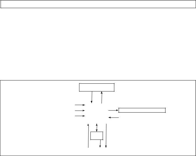
Figure 1–1 is a block diagram of the basic system inputs and outputs.
SHIFT SELECTOR
RANGE AND |
DISPLAY |
||||
MODE SWITCH |
|||||
|
|
|
|
|
|
SPEED SENSORS |
|
|
|
|
|
|
|
|
|
||
|
|
|
|
|
|
THROTTLE POSITION SENSOR |
|
|
ECU |
|
SOLENOIDS |
|
|
|
|
|
|
VEHICLE/ENGINE |
|
|
|
|
TEMPERATURE SENSOR |
COMMUNICATION LINKS |
|
|
|
|
(SUMP) |
|
|
|
|
|
|
VIM
INPUTS |
|
OUTPUTS |
V03469.01 |
Figure 1–1. Electronic Control Unit Block Diagram
Figure 1–2 shows the CEC 2 electronic control components.
CEC 2 consists of the following elements:
•Remote 12/24V Max Feature Sealed Electronic Control Unit (ECU)
•Remote Pushbutton or Lever Shift Selector
•Optional Secondary Shift Selector
•Throttle Position Sensor (TPS) (or electronic engine throttle data)
•Input, Turbine, and Output Speed Sensors
•Electro-Hydraulic Valve Bodies
•Wiring Harnesses
•Vehicle Interface Module (VIM)
NOTE: • |
All external harnesses are OEM supplied |
• |
The VIM is an OEM option |
Copyright © 2000 General Motors Corp. |
1–1 |

COMMERCIAL ELECTRONIC CONTROLS 2 (CEC 2) TROUBLESHOOTING MANUAL
GENERAL DESCRIPTION
ELECTRONIC CONTROL UNIT
(ECU)
 BLACK
BLACK
BLUE
SELECTOR (S) HARNESS 

“S” CONNECTOR (BLACK)
Y
GRA
BLUE |
TRANSMISSION (T) |
|
|
|
HARNESS |
|
“T” |
|
CONNECTOR |
J 1939 |
(BLUE) |
|
|
CONNECTOR |
|
(OPTIONAL) |
|
PRO-LINK®
DIAGNOSTIC
TOOL DIAGNOSTIC DATA READER (DDR)
CONNECTOR
VIW–S  CONNECTOR
SCI (J 1587)
CONNECTOR REMOTE (OPTIONAL) LEVER
SELECTOR
DEUTSCH DDR
CONNECTOR (OPTIONAL)
SHIFT
SELECTOR
CONNECTOR
REMOTE
PUSHBUTTON
SELECTOR
|
THROTTLE POSITION |
|
|
SENSOR (TPS) |
|
R |
CONNECTOR |
|
THROTTLE |
||
N |
||
D |
||
|
POSITION |
|
|
SENSOR (TPS) |
|
|
TURBINE |
|
|
SPEED SENSOR |
|
|
CONNECTOR |
|
|
Bulkhead Connector (Optional) |
VEHICLE (V) HARNESS
“V”  CONNECTOR
(GRAY)
TPS
CONNECTOR (OPTIONAL)
VEHICLE INTERFACE MODULE (VIM)
TRIM
BOOST
CONNECTOR
INPUT (ENGINE)
SPEED SENSOR
CONNECTOR
VIW–V
CONNECTOR
VIM
CONNECTORS
TEMP SENSOR/
LOCKUP
CONNECTOR
OUTPUT
SPEED SENSOR
CONNECTOR
TRANSMISSION
MAIN VALVE
BODY
CONNECTOR
NOTE: Illustration is not to scale. Actual harness configuration may differ from this illustration.
V06587
.
Figure 1–2. CEC 2 Components
1–2 |
Copyright © 2000 General Motors Corp. |
COMMERCIAL ELECTRONIC CONTROLS 2 (CEC 2) TROUBLESHOOTING MANUAL
GENERAL DESCRIPTION
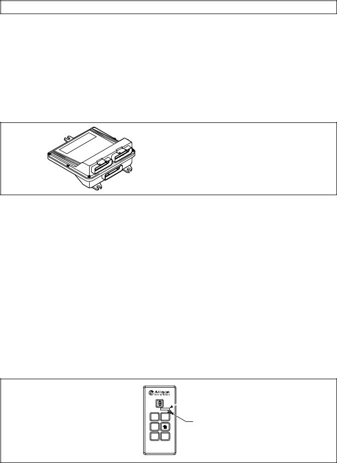
1–2. ELECTRONIC CONTROL UNIT (ECU)
The ECU (Figure 1–3) contains the microcomputer which is the brain of the control system. The ECU receives and processes information defining: shift selector position, throttle position, sump temperature, input speed, turbine speed, and transmission output speed. The ECU uses the information to control transmission solenoids and valves, supply system status, and provide diagnostic information.
Each ECU has a date code stamped on the label which is attached to the outer case of the ECU. This is the date when the ECU passed final test. This date is commonly used to denote the change configuration level of the ECU. It is normal for the ECU date displayed electronically to be a few days prior to the date shown on the label.
 BLACK
BLACK
BLUE
Y
GRA
BLUE
ECU
NOTE: ECU wiring harness connector retainers are individually keyed and color-coded to
ensure that the proper connector is attached to the correct ECU socket. The color of the connector retainer should match the color of the connector strain relief (see Appendix C, Paragraph 1–1).
V03352.01
Figure 1–3. Electronic Control Unit (ECU)
1–3. SHIFT SELECTOR
Pushbutton and lever shift selectors for CEC 2 are remote mounted from the ECU and connected to the ECU by a wiring harness. Both of these shift selectors have a single digit LED display and a mode indicator LED. During normal transmission operation, illumination of the LED indicator shows that a secondary or special operating condition has been selected by pressing the MODE button. During diagnostic display mode, illumination of the LED indicator shows that the displayed diagnostic code is active. Display brightness is regulated by the same vehicle potentiometer that controls dash light display brightness. More information on both types of shift selectors is continued below.
A.Pushbutton Shift Selector (Figure 1–4)
There is a full-function pushbutton shift selector. A full-function shift selector has a MODE button
and diagnostic display capability through the single digit LED display. The full-function pushbutton shift selector has six (6) pushbuttons which are R (Reverse), N (Neutral), D (Drive), (Down),
|
(Up), and MODE. Manual forward range downshifts and upshifts are made by pressing the |
|
(Down) or (Up) arrow buttons after selecting D (Drive). The N (Neutral) button has a raised lip to |
aid in finding it by touch. The MODE button is pressed to select a secondary or special operating condition, such as ECONOMY shift schedule. Diagnostic information is obtained by pressing the(Up) and (Down) arrow buttons at the same time.
 MODE ID
R MODE
MODE INDICATOR (LED)
N
D  PUSHBUTTON
SELECTOR
V06588
Figure 1–4. Pushbutton Shift Selector
Copyright © 2000 General Motors Corp. |
1–3 |
COMMERCIAL ELECTRONIC CONTROLS 2 (CEC 2) TROUBLESHOOTING MANUAL
GENERAL DESCRIPTION
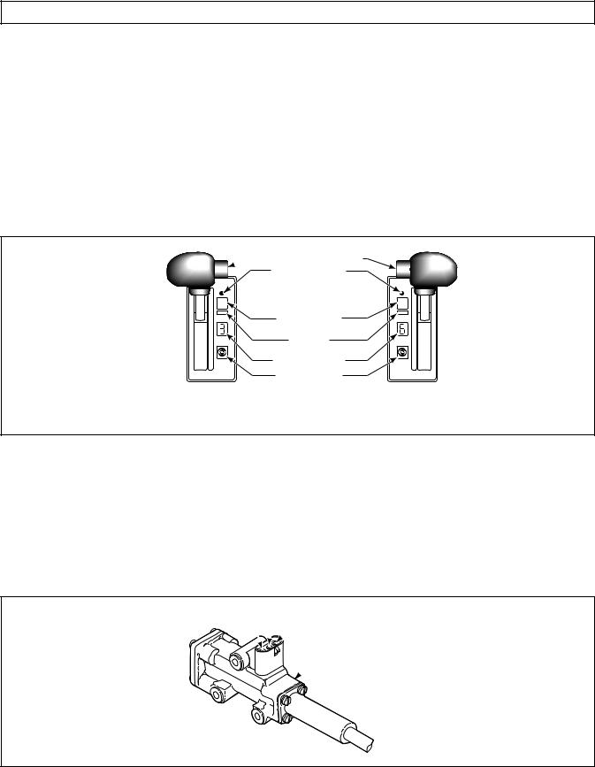
B.Lever Shift Selector (Figure 1–5)
The lever shift selector can have as many as six forward range positions, as well as two R (Reverse) positions (R1 and R2) and N (Neutral). There is a hold override button which must be pressed and held in order to move between certain selector positions. The hold override button must be pressed when shifting between R, N, and D. The hold override button is released when the desired selector position is reached. The selector lever can be moved freely between D and the numbered forward ranges without pressing the hold override button. The lever selector can be chosen with the lever on the left side or on the right side and with the R (Reverse) position toward the front or toward the rear of the selector. Diagnostic information is obtained from the single digit LED display by pressing the “display mode” button.

 HOLD OVERRIDE BUTTON
MODE INDICATOR (LED)
1 |
|
R |
|
MODE |
|
MODE |
|
2 |
|
N |
|
3 |
MODE BUTTON |
D |
|
4 |
5 |
||
|
|||
5 |
MODE ID |
4 |
|
D |
3 |
||
N |
|
2 |
|
R |
DIGITAL DISPLAY |
1 |
|
|
|
DISPLAY MODE/ |
|
|
DIAGNOSTIC BUTTON |
SIX-SPEED, RIGHT-HAND |
|
SIX-SPEED, LEFT-HAND |
|
|
LEVER SELECTOR |
LEVER SELECTOR |
|
WITH REVERSE TO REAR |
WITH REVERSE TO FRONT |
V03355.02 |
Figure 1–5. Typical Lever Shift Selector
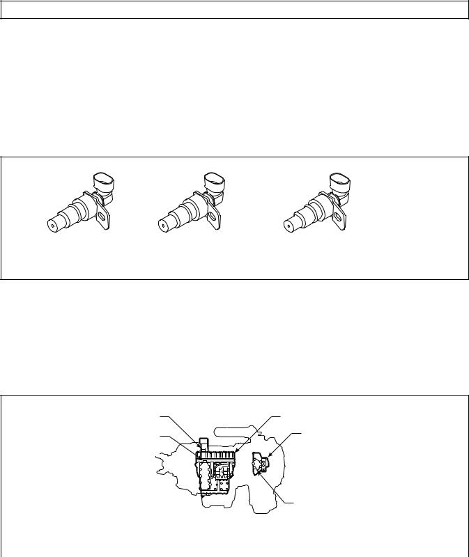
1–4. THROTTLE POSITION SENSOR (Figure 1–6)
The Throttle Position Sensor (TPS) can be mounted to the engine, chassis, or transmission. The TPS contains a pull actuation cable and a potentiometer. One end of the cable is attached to the engine fuel lever and the other, inside a protective housing, to the TPS potentiometer. Output voltage from the TPS is directed to the ECU through the external harness. The voltage signal indicates the throttle position and, in combination with other input data, determines shift timing.
A
 B
B
 C
C
 THROTTLE SENSOR
V00628
Figure 1–6. Throttle Position Sensor
1–4 |
Copyright © 2000 General Motors Corp. |
COMMERCIAL ELECTRONIC CONTROLS 2 (CEC 2) TROUBLESHOOTING MANUAL
GENERAL DESCRIPTION
1–5. SPEED SENSORS (Figure 1–7)
Three speed sensors — input speed, turbine speed, and output speed — provide information to the ECU. The input speed signal is generated by the gear teeth on the top PTO gear. The turbine speed signal is generated by serrations on the pitot can attached to the splitter low drum. The output speed signal is generated by a toothed member attached to the output shaft. The speed ratios between the various speed sensors allow the ECU to determine if the transmission is in the selected range. Hydraulic problems are detected by comparing the speed sensor information for the current range to that range’s speed sensor information stored in the ECU memory.
INPUT |
TURBINE |
OUTPUT |
(EXTERNAL) |
(EXTERNAL) |
(EXTERNAL) |
V06589
Figure 1–7. Speed Sensors
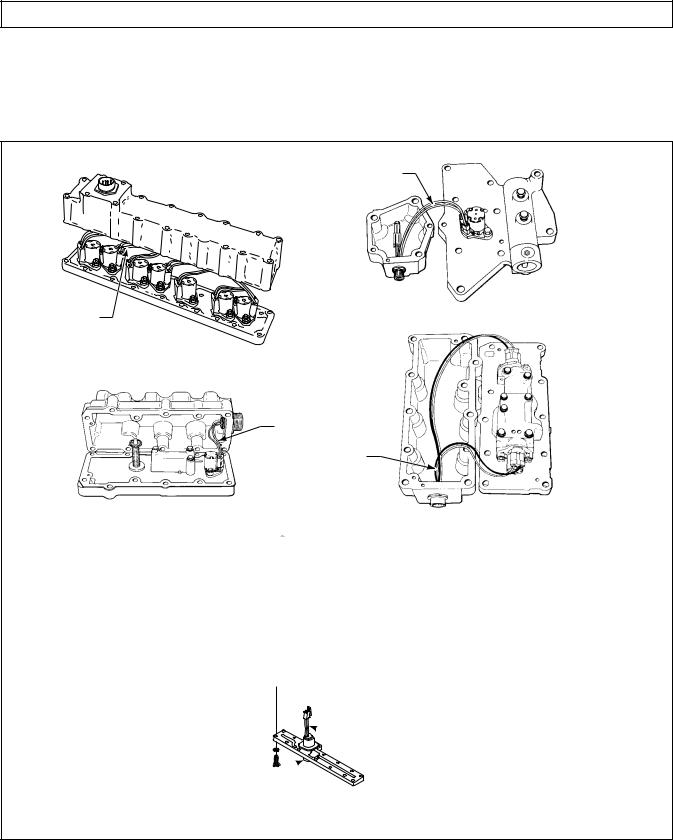
1–6. ELECTRO-HYDRAULIC VALVE COMPONENTS (Figure 1–8)
The CEC 2 electro-hydraulic valve bodies contain various solenoids to control the absence or presence of solenoid pressure. Solenoid pressure, or lack of pressure, positions shift valves which apply or release transmission clutches to produce the range commanded by the ECU inputs. The ECU is connected to the solenoids by a wiring harness with sealed multi-pin twist-lock connectors at the control valve bodies.
MAIN CONNECTOR – ALL MODELS
(Solenoids A – G)
PLATE & COVER CONNECTOR
(Solenoids H, I, & J)
8610, 9610, 9810
TRIM BOOST CONNECTOR
(Solenoid J) 5610, 6610
MAIN VALVE BODY
LOCKUP VALVE BODY
LOCKUP CONNECTOR – ALL MODELS (K Solenoid and sump
temperature sensor)
5/6/8/9000 SERIES OFF-HIGHWAY TRANSMISSION |
V06590 |
|
|
Figure 1–8. CEC 2 Control Module |
|
Copyright © 2000 General Motors Corp. |
1–5 |

COMMERCIAL ELECTRONIC CONTROLS 2 (CEC 2) TROUBLESHOOTING MANUAL
GENERAL DESCRIPTION
The sump temperature sensor in the lockup body sends information to the ECU. When oil temperature is below –25ºF (–32ºC), all shifts are blocked. When oil temperature is between –25ºF a (–32ºC) and 20ºF a (–7ºC), transmission shifting is limited to neutral, to limited forward rangesa, and reverse. Above 250ºF a (121ºC), the Hot light comes on (if equipped), and a trouble code is stored in memory. See chart in Section 5, Code 24 for sump temperature sensor (thermistor) characteristics. Some applications (emergency vehicles, for example) are often exempt from shift inhibit during temperature extremes, but the CHECK TRANS light may still come on and codes may be logged in the ECU memory.
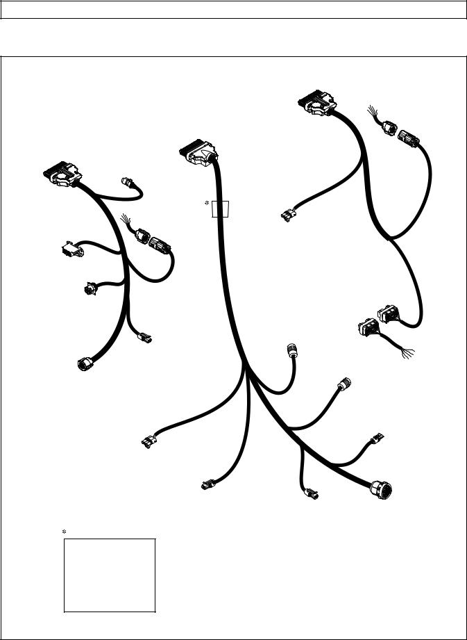
1–7. WIRING HARNESSES
A.External Wiring Harness (Figure 1–9)
CEC 2 uses three external wiring harnesses to provide a connection between the ECU, the transmission (including input, turbine, and output speed sensors), the throttle position sensor, the vehicle interface module (VIM), shift selectors, diagnostic tool connector, and vehicle interface. The transmission harness may include a bulkhead fitting to separate cab and chassis components.
NOTE: Allison Transmission is providing for service of wiring harnesses and wiring harness components as follows:
•Repair parts for the internal wiring harness and for wiring harness components attached to the shift selector will be available through the Allison Transmission Parts Distribution Center (PDC). Use the P/N from your appropriate parts catalog or from Appendix C in this manual. Allison Transmission is responsible for warranty on these parts.
•Repair parts for the external harnesses and external harness components must be obtained from St. Clair Technologies Inc. (SCTI). SCTI provides parts to any Allison customer or OEM and is responsible for warranty on these parts. SCTI recognizes ATD, manufacturers, and SCTI part numbers. SCTI provides a technical HELPLINE at 519-627-1673 (Wallaceburg). SCTI will have parts catalogs available. The SCTI addresses and phone numbers for parts outlets are:
St. Clair Technologies, Inc. |
St. Clair Technologies, Inc. |
St. Clair Technologies, Inc. |
1050 Old Glass Road |
1111 Mikesell Street |
c/o Mequilas Tetakawi |
Wallaceburg, Ontario N8A 3T2 |
Charlotte, MI 48813 |
Carr. Internationale KM 1969 |
Phone: (519) 627-1673 |
Phone: (517) 541-8166 |
Guadalajara – Nogales, KM2 |
Fax: (519) 627-4227 |
Fax: (517) 541-8167 |
Empalme, Sonora, Mexico |
|
|
Phone: 011-52-622-34661 |
|
|
Fax: 011-52-622-34662 |
•St. Clair Technologies, Inc. stocks a CEC 2 external harness repair kit, P/N 29532362, as a source for some external harness repair parts. SCTI is the source for external harness repair parts.
a This is a programmed value subject to change.
1–6 |
Copyright © 2000 General Motors Corp. |
COMMERCIAL ELECTRONIC CONTROLS 2 (CEC 2) TROUBLESHOOTING MANUAL
GENERAL DESCRIPTION
|
|
|
|
|
VEHICLE (V) |
|
|
|
|
|
|
|
HARNESS |
|
|
TRANSMISSION (T) |
“V” |
|
|
VIW–V |
|
|
CONNECTOR |
|
|
||
|
|
|
|
CONNECTOR |
||
|
|
HARNESS |
(GRAY) |
|
|
|
|
|
|
|
|
||
SELECTOR (S) |
“T” |
|
|
|
|
|
HARNESS |
CONNECTOR |
|
|
|
|
|
|
|
(BLUE) |
|
|
|
|
|
|
J 1939 |
|
|
|
|
|
|
CONNECTOR |
|
|
|
|
|
|
(OPTIONAL) |
|
|
|
|
|
“S” |
|
|
|
|
|
CONNECTOR |
|
|
|
|
|
|
(BLACK) |
|
|
|
|
|
|
PRO-LINK® |
|
|
|
|
|
|
DIAGNOSTIC |
VIW–S |
TPS |
|
|
|
|
TOOL |
DIAGNOSTIC |
|
|
|
||
DATA READER (DDR) |
CONNECTOR |
CONNECTOR |
|
|
|
|
|
CONNECTOR |
|
(OPTIONAL) |
|
|
|
|
DEUTSCH DDR |
|
|
|
|
|
|
CONNECTOR |
|
|
|
|
|
|
(OPTIONAL) |
|
|
|
|
|
|
|
|
|
|
|
VIM |
|
|
SCI (J 1587) |
|
CONNECTORS |
||
|
|
CONNECTOR |
TRIM |
|
|
|
|
|
(OPTIONAL) |
|
|
|
|
|
|
BOOST |
|
|
|
|
|
|
|
|
|
|
|
|
|
|
CONNECTOR |
|
|
|
|
SHIFT |
|
|
|
|
TEMP SENSOR/ |
|
|
|
|
|
LOCKUP |
|
|
SELECTOR |
|
|
|
||
|
|
|
|
CONNECTOR |
||
|
CONNECTOR |
|
|
|
||
|
|
|
|
|
||
|
|
|
|
|
|
OUTPUT |
|
|
|
|
|
|
SPEED SENSOR |
|
|
|
|
|
|
CONNECTOR |
|
|
THROTTLE POSITION |
|
|
|
|
|
|
SENSOR (TPS) |
|
|
|
|
|
|
CONNECTOR |
|
|
|
|
|
|
TURBINE |
|
|
|
|
|
|
SPEED SENSOR |
INPUT (ENGINE) |
|
TRANSMISSION |
|
|
|
CONNECTOR |
|
|||
|
|
SPEED SENSOR |
||||
|
|
|
MAIN VALVE |
|||
CONNECTOR |
BODY |
Bulkhead Connector (Optional) |
CONNECTOR |
|
NOTE: Illustration is not to scale. Actual harness configuration may differ from this illustration.
V06591
Figure 1–9. CEC 2 External Wiring Harnesses
Copyright © 2000 General Motors Corp. |
1–7 |
COMMERCIAL ELECTRONIC CONTROLS 2 (CEC 2) TROUBLESHOOTING MANUAL
GENERAL DESCRIPTION
B.Internal Wiring Harnesses (Figure 1–10)
The internal wiring harnesses provide connection between the external harness, solenoids, and the temperature sensor.
INTERNAL
HARNESS
A
B
C
D
E
F
G
INTERNAL
HARNESS
LOCKUP BODY
ALL MODELS
MAIN BODY SOLENOIDS & COVER
ALL MODELS
INTERNAL
HARNESS
INTERNAL
HARNESS
TRIM BOOST PLATE & COVER |
FIRST or LOW-LOW PLATE & COVER |
|
9610 MODEL |
||
8610, 9810 MODEL |
||
|
 INTERNAL
HARNESS
J SOLENOID CONNECTOR
TRIM BOOST TRIMMER COVER
5610, 6610 MODEL
L06592
Figure 1–10. CEC 2 Internal Wiring Harnesses
1–8 |
Copyright © 2000 General Motors Corp. |
COMMERCIAL ELECTRONIC CONTROLS 2 (CEC 2) TROUBLESHOOTING MANUAL
GENERAL DESCRIPTION
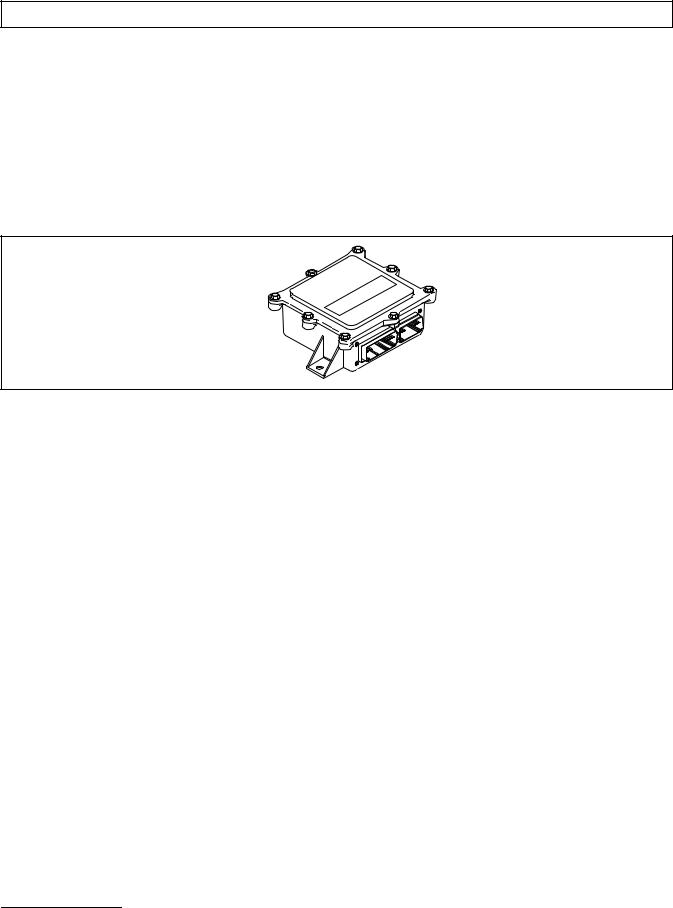
1–8. VEHICLE INTERFACE MODULE (Figure 1–11)
The vehicle interface module (VIM) provides relays, fuses, and connection points to interface with the vehicle electrical system. VIMs are available for both 12V and 24V electrical systems. The VIM for 12V systems uses all 12V relays. The VIM for 24V systems has all 24V relays. Refer to the Parts Catalog for the transmission assembly number that you are servicing for detailed parts information. Refer to Pages B–19 and B–20 for VIM wire number and terminal information. Further information is available in Appendix E.
Some OEMs may provide their own equivalent for the VIM which performs the same functions as the VIM shown in Figure 1–11.
V00631.02
Figure 1–11. Vehicle Interface Module (VIM)
1–9. AUTODETECT FEATURE
Autodetect is active on the first 10a engine starts. Autodetect takes place within the first 5–25a seconds of each engine start monitored. For CEC 2, autodetect searches for the presence of a throttle information source. Autodetect searches for a TPS (analog) source or a data link source via J1939 or J1587.
a This is a programmed value subject to change.
Copyright © 2000 General Motors Corp. |
1–9 |

COMMERCIAL ELECTRONIC CONTROLS 2 (CEC 2) TROUBLESHOOTING MANUAL
GENERAL DESCRIPTION
NOTES
1–10 |
Copyright © 2000 General Motors Corp. |

COMMERCIAL ELECTRONIC CONTROLS 2 (CEC 2) TROUBLESHOOTING MANUAL
SECTION 2 — DEFINITIONS AND ABBREVIATIONS
2–1. CHECK TRANS LIGHT
When the ECU detects an abnormal condition, the CHECK TRANS light (usually located on the vehicle instrument panel) illuminates and action is automatically taken to protect operator, vehicle, and the transmission. A diagnostic code will nearly always be registered when the CHECK TRANS light is on; however, not all diagnostic codes will turn on the CHECK TRANS light. Codes related to the CHECK TRANS light are detailed in the code chart (refer to Section 5).
Illumination of the CHECK TRANS light indicates that a condition was detected that requires service attention. Operation of the transmission may or may not be restricted. Depending upon the cause for the CHECK TRANS light illumination, the ECU may or may not respond to shift selector requests. The transmission may be locked in a range. The range selected will flash on the shift selector display. Both upshifts and downshifts may be restricted when the CHECK TRANS light is illuminated. Seek service assistance as soon as possible.
Each time the engine is started, the CHECK TRANS light illuminates briefly and then goes off. This momentary lighting shows the light circuit is working properly. If the light does not come on during engine start, request service immediately.
2–2. DIAGNOSTIC DATA READER (Figure 2–1)
The current Diagnostic Data Reader (DDR) is the Pro-Link® 9000 diagnostic tool which is available through Micro Processor Systems, Inc. (MPSI). A portable microcomputer-based receiver/transmitter/display unit, the Pro-Link® transmits and receives data to and from the ECU, processes the data, and displays appropriate information. Use the Pro-Link® during installation checkout and troubleshooting. There is a new Pro-Link® cartridge needed for use with CEC 2. The new Multi-Protocol Cartridge (MPC) contains a programmed PCMCIA card which allows for reprogramming of GPI/GPO packages. Reprogramming includes selection of a GPI/GPO package, enabling/disabling of wires and modification of certain data parameters. Operating instructions are supplied with each Pro-Link® and further information is also included in Appendix J of this manual. Connect the Pro-Link® 9000 to the diagnostic connector provided in the selector wiring harness.
Manufacturer’s description and part numbers for the Pro-Link® are as follows: |
|
Product |
Part Number |
Allison CEC 1 and 2 transmission systems reprogramming card* |
800007 |
Includes: Allison CEC 1 and 2 systems card and manual |
|
* Allison training certificate required |
|
Pro-Link® Plus main unit |
108004 |
Includes: VT Pro-Link® software, power and data cable, and storage case |
|
Multi-Protocol Cartridge (MPC) |
208040 |
Supports: J1708, J1939, 160 baud, and ISO 9141 communications, |
|
OEM specific application memory cards |
|
Printer |
178001 |
Includes: One roll of thermal paper, an AC power converter, |
|
Instruction manual, built-in Ni-Cad battery and a cable to connect |
|
the printer to the Pro-Link® Plus |
|
6-Pin Deutsch Adapter |
404024 |
PC/Terminal Cable Set |
501005 |
Required to update PC card application |
|
Pro-Link® 9000 Operator’s Manual |
950007 |
Copyright © 2000 General Motors Corp. |
2–1 |
COMMERCIAL ELECTRONIC CONTROLS 2 (CEC 2) TROUBLESHOOTING MANUAL
DEFINITIONS AND ABBREVIATIONS
NOTE: The new MPC must be used to reprogram CEC 2 systems.
V04842
Figure 2–1. Pro-Link® 9000 Diagnostic Tool
2–3. ABBREVIATIONS
A/N |
Assembly Number |
Amp |
Unit of electrical current. |
CAN |
Controller Area Network — A network for all SAE J1939 communications in a vehicle |
|
(engine, transmission, etc.) |
CEC 1/CEC 2 |
Commercial Electronic Controls 1 or 2 — Designation for electronic controls used in |
|
off-highway and some older on-highway transmissions. |
COP |
Computer Operating Properly — Hardware protection which causes the ECU to reset if |
|
software gets lost. |
CT |
Closed Throttle |
DDR |
Diagnostic Data Reader — Diagnostic tool; most current version is the Pro-Link® 9000 |
|
made by MicroProcessor Systems, Inc. Used to interrogate the ECU for diagnostic |
|
information and for reprogramming I/O packages in a calibration. |
DDU |
Digital Display Unit — Optional means of obtaining diagnostic information. |
DNS |
DO NOT SHIFT — Refers to the DO NOT SHIFT diagnostic response during which the |
|
CHECK TRANS light is illuminated and the transmission will not shift and will not |
|
respond to the Shift Selector. |
DVOM |
Digital volt/ohmmeter |
ECU |
Electronic Control Unit (also commonly referred to as the “computer”) |
GPI |
General Purpose Input — Input signal to the ECU to request a special operating mode or |
|
condition. |
GPO |
General Purpose Output — Output signal from the ECU to control vehicle components |
|
(such as PTOs, backup lights, etc.) or allow a special operating mode or condition. |
J1587 |
Engine/transmission serial data communications link. |
J1939 |
High-speed vehicle serial data communications link. |
LED |
Light-Emitting Diode — Electronic device used for illumination. |
2–2 |
Copyright © 2000 General Motors Corp. |

COMMERCIAL ELECTRONIC CONTROLS 2 (CEC 2) TROUBLESHOOTING MANUAL
DEFINITIONS AND ABBREVIATIONS
2–3. ABBREVIATIONS (cont’d)
NVL |
Neutral Very Low — The ECU has sensed turbine speed below 150 rpm when output |
|
speed is below 100 rpm and engine speed is above 400 rpm when N (Neutral) was selected. |
OEM |
Original Equipment Manufacturer — Maker of vehicle or equipment. |
Ohm |
Unit of electrical resistance. |
PCCS |
PROM Calibration Configuration System |
PCMCIA |
Personal Computer Memory Card International Association — Memory device for use |
|
with Pro-Link® containing Allison Transmission programming and diagnostics. |
PROM |
Programmable Read Only Memory |
PSS |
Primary Shift Selector — Main shift selector in a two-selector control system. |
PTO |
Power Takeoff |
SCI |
Serial Communication Interface — Used to transmit data and messages between the |
|
diagnostic tool and the ECU and other systems such as electronically-controlled engines. |
SOL OFF |
All SOLenoids OFF |
SPI |
Serial Peripheral Interface — The means of communication between the microprocessor |
|
and the interface circuits. |
SSS |
Secondary Shift Selector — Alternate shift selector in a two-selector control system. |
TPS |
Throttle Position Sensor — Potentiometer for signaling the position of the engine fuel |
|
control lever. |
V |
Version — Abbreviation used in describing ECU software levels. |
V |
Volt — i.e., 24V |
VDC |
Volts Direct Current (DC) |
VIM |
Vehicle Interface Module — A watertight box containing relays and fuses — interfaces the |
|
transmission electronic control system with components on the vehicle. |
VIW |
Vehicle Interface Wiring — Interfaces ECU programmed input and output functions with |
|
the vehicle wiring. |
Volt |
Unit of electrical force. |
VOM |
Volt/ohmmeter |
WOT |
Wide Open Throttle |
∞ |
Infinity — Condition of a circuit with higher resistance than can be measured, effectively |
|
an open circuit. |
Copyright © 2000 General Motors Corp. |
2–3 |

COMMERCIAL ELECTRONIC CONTROLS 2 (CEC 2) TROUBLESHOOTING MANUAL
DEFINITIONS AND ABBREVIATIONS
NOTES
2–4 |
Copyright © 2000 General Motors Corp. |

COMMERCIAL ELECTRONIC CONTROLS 2 (CEC 2) TROUBLESHOOTING MANUAL
SECTION 3 — BASIC KNOWLEDGE
3–1. BASIC KNOWLEDGE REQUIRED
To service CEC 2, the technician must understand basic electrical concepts. Technicians need to know how to use a volt/ohmmeter (VOM) to make resistance and continuity checks. Most troubleshooting checks consist of checking resistance, continuity, and checking for shorts between wires and to ground. The technician should be able to use jumper wires and breakout harnesses and connectors. Technicians unsure of making the required checks should ask questions of experienced personnel or find instruction.
The technician should also have the mechanical aptitude required to connect pressure gauges or transducers to identified pressure ports used in the troubleshooting process. Pressure tap locations and pressure values are shown in the Service Manual for the transmission being checked.
Input power, ground, neutral start circuitry, etc., can cause problems with electronic controls or vehicle functioning and may not generate a diagnostic code. A working knowledge of CEC 2 vehicle installation is necessary in troubleshooting installation-related problems.
Refer to Section 8 for information concerning performance complaints (non-code) troubleshooting. A complete wiring schematic is shown in Appendix G. Refer to the CEC 2 Controls and Off-Highway Sales Tech Data Book (SA3227EN) for information concerning electronic controls installation and the Installation Checklist. Reliable transmission operation and performance depend upon a correctly installed transmission. Also review the Installation Checklist in the Off-Highway Sales Tech Data Book (SA1861EN) to ensure proper installation.
NOTE: Allison Transmission is providing for service of wiring harnesses and wiring harness components as follows:
•Repair parts for the internal wiring harness and for wiring harness components attached to the shift selector will be available through the Allison Transmission Parts Distribution Center (PDC). Use the P/N from your appropriate parts catalog or from Appendix C in this manual. Allison Transmission is responsible for warranty on these parts.
•Repair parts for the external harnesses and external harness components must be obtained from St. Clair Technologies Inc. (SCTI). SCTI provides parts to any Allison customer or OEM and is responsible for warranty on these parts. SCTI recognizes ATD, manufacturers, and SCTI part numbers. SCTI provides a technical HELPLINE at 519-627-1673 (Wallaceburg). SCTI will have parts catalogs available. The SCTI addresses and phone numbers for parts outlets are:
St. Clair Technologies, Inc. |
St. Clair Technologies, Inc. |
St. Clair Technologies, Inc. |
1050 Old Glass Road |
1111 Mikesell Street |
c/o Mequilas Tetakawi |
Wallaceburg, Ontario N8A 3T2 |
Charlotte, MI 48813 |
Carr. Internationale KM 1969 |
Phone: (519) 627-1673 |
Phone: (517) 541-8166 |
Guadalajara – Nogales, KM2 |
Fax: (519) 627-4227 |
Fax: (517) 541-8167 |
Empalme, Sonora, Mexico |
|
|
Phone: 011-52-622-34661 |
|
|
Fax: 011-52-622-34662 |
•St. Clair Technologies, Inc. stocks a CEC 2 external harness repair kit, P/N 29532362, as a source for some external harness repair parts. SCTI is the source for external harness repair parts.
Copyright © 2000 General Motors Corp. |
3–1 |

COMMERCIAL ELECTRONIC CONTROLS 2 (CEC 2) TROUBLESHOOTING MANUAL
BASIC KNOWLEDGE
3–2. USING THE TROUBLESHOOTING MANUAL
Use this manual as an aid to troubleshooting CEC 2. Every possible problem and its solution cannot be encompassed by any manual. However, this manual does provide a starting point from which most problems can be resolved.
3–3. SYSTEM OVERVIEW
CEC 2 functions are controlled by the ECU. The ECU reads shift selector range selection, output speed, and throttle position to determine when to command a shift. When a shift occurs, the ECU monitors turbine speed, output speed, and throttle position during the shift.
When the ECU detects an electrical fault, it logs a diagnostic code indicating the faulty circuit and may alter the transmission operation to prevent or reduce damage.
When the ECU detects a non-electrical problem while trying to make a shift, the ECU may try that shift a second or third time before setting a diagnostic code. Once that shift has been retried, and a fault is still detected, the ECU sets a diagnostic code and holds the transmission in a lock-to-range mode of operation.
3–4. IMPORTANT INFORMATION IN THE TROUBLESHOOTING PROCESS
Before beginning the troubleshooting process, read and understand the following:
•CEC 2 wire identification presents the wire number followed by the ECU terminal source
(i.e., 157-S30). If there is a letter suffix following the wire number, there is a splice between the ECU source and wire destination (i.e., 116A-T19).
•Shut off the engine and ignition before any harness connectors are disconnected or connected.
•Remember to do the following when checking for shorts and opens:
—Shorts: Minimize movement of wiring harnesses when looking for shorts. Shorts involve wire-to- wire or wire-to-ground contacts and moving the harnesses may eliminate the problem.
—Opens: Wiggle connectors, harnesses, and splices when looking for opens. This simulates vehicle movements which occur during actual operation.
•When disconnecting a harness connector, be sure that pulling force is applied to the connector itself and not the wires extending from the connector.
•Resistance checks involving the wiring between the ECU connectors and other components adds about one ohm of resistance to the component resistance shown.
•Inspect all connector terminals for damage. Terminals may have bent or lost the necessary tension to maintain firm contact.
•Clean dirty terminals or connectors with isopropyl alcohol and a cotton swab, or a good quality, nonresidue, non-lubricating, cleaning solvent such as LPS Electro Contact Cleaner® or LPS NoFlash Electro Contact Cleaner® .
3–2 |
Copyright © 2000 General Motors Corp. |

COMMERCIAL ELECTRONIC CONTROLS 2 (CEC 2) TROUBLESHOOTING MANUAL
BASIC KNOWLEDGE
The cleaning solvent must not be chlorine based, contain petroleum distillates, or conduct electricity. The cleaning solvent should evaporate quickly to prevent the possibility of
CAUTION:
condensation within the connectors. Always blow or shake any excess cleaner from the connector before assembling it to its mating connector or hardware. Cleaner trapped in the connector can affect the connector seal. (Refer to SIL 17-TR-94 for detailed information on the recommended cleaners.)
CAUTION:
Care should be taken when welding on a vehicle equipped with electronic controls. Refer to Appendix E, Paragraph 1–1.
•Diagnostic codes displayed after system power is turned on with a harness connector disconnected, can be ignored and cleared from memory. Refer to Section 5, Diagnostic Codes, for the code clearing procedure.
3–5. BEGINNING THE TROUBLESHOOTING PROCESS
1.Begin troubleshooting by checking the transmission fluid level and ECU input voltage. Remember that some problems may be temperature related. Do troubleshooting at the temperature level where the problem occurs. Check diagnostic codes by:
•Using the shift selector display. (See Paragraph 5–2 for code reading.)
•Using the Pro-Link® 9000 diagnostic tool.
2.When a problem exists but a diagnostic code is not indicated, refer to the Performance Complaint Section (Section 8) for a listing of various electrical and hydraulic problems, their causes, and remedies.
3.If a diagnostic code is found in the ECU memory, record all available code information and clear the active indicator (refer to Section 5).
4.Test drive the vehicle to confirm a diagnostic code or performance complaint.
•If the code reappears, refer to the Diagnostic Code section (Section 5) and the appropriate code chart. The Diagnostic Code section lists diagnostic codes and their description. Locate the appropriate troubleshooting chart and follow the instructions.
•If the code does not reappear, it may be an intermittent problem. Use the Pro-Link® and the code display procedure described in Section 5. The code display procedure will indicate the number of times the diagnostic code has occurred. Refer to the troubleshooting chart for possible cause(s) of the problem.
•Appendix A deals with the identification of potential circuit problems. Refer to Appendix A if a circuit problem is suspected.
NOTE: Information concerning specific items is contained in the appendices located in the back of this manual. The appendices are referred to throughout the manual.
Copyright © 2000 General Motors Corp. |
3–3 |

COMMERCIAL ELECTRONIC CONTROLS 2 (CEC 2) TROUBLESHOOTING MANUAL
BASIC KNOWLEDGE
NOTES
3–4 |
Copyright © 2000 General Motors Corp. |
COMMERCIAL ELECTRONIC CONTROLS 2 (CEC 2) TROUBLESHOOTING MANUAL
SECTION 4 — WIRE CHECK PROCEDURES
4–1. CHECKING OPENS, SHORTS BETWEEN WIRES, AND SHORTS-TO-GROUND
(Use Digital Volt/Ohmmeter J 34520-A and Jumper Wire Set J 39197)
NOTE: Please refer to Paragraph 3–5 to begin the troubleshooting process.
1.Make sure all connectors are tightly connected and re-check the circuit.
2.Disconnect and inspect all connectors.
3.Thoroughly clean corroded or dirty terminals. If dirty or corroded terminals are the probable cause of the problems, reconnect the clean connectors and operate the vehicle normally. If the problem recurs, proceed with Step (4).
The cleaning solvent must not be chlorine based, contain petroleum distillates, or conduct electricity. The cleaning solvent should evaporate quickly to prevent the
CAUTION:
possibility of condensation within the connectors. Always blow or shake any excess cleaner from the connector before assembling it to its mating connector or hardware. Cleaner trapped in the connector can affect the connector seal. (Refer to SIL 17-TR-94 for detailed information on the recommended cleaners.)
4.Review the CEC 2 wire numbering system described in Paragraph 3–4.
5.If all connectors are clean and connected correctly, determine which wires in the chassis harness are indicated by the diagnostic code. For example, Code 45 12, indicates a failure in the F solenoid circuit — wires 102-T1 and 120-T4.
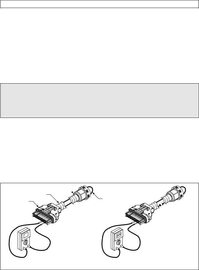
a. Check continuity of wires 102-T1 and 120-T4 by performing the following (refer to Figure 4–1):
(1)Disconnect the blue “T” connector from the ECU and disconnect the harness from the transmission main connector. At one end of the harness, using jumper wire kit J 39197 and connector probes in J 39775-CP, connect wire 102-T1 and 120-T4 to each other, being careful not to distort the terminals. Jumping the wires together creates a circuit between wires 102-T1 and 120-T4.
TRANSMISSION CONNECTOR
WIRING HARNESS
JUMPER
ECU “T” CONNECTOR
+
0
|
VOLT/OHM- |
– |
METER |
|
(VOM) |
0 OHMS
Circuit has continuity. Jumper from 102 or 120 to another wire produces a complete circuit. VOM reading is near zero Ohms.
– + 
 OHMS
OHMS
Circuit does not have continuity due |
|
to a broken wire (open circuit). |
|
VOM reading is very high |
|
(infinite Ohms or OL – overlimit). |
V03374.01 |
|
Figure 4–1. Open Circuit
Copyright © 2000 General Motors Corp. |
4–1 |
COMMERCIAL ELECTRONIC CONTROLS 2 (CEC 2) TROUBLESHOOTING MANUAL
WIRE CHECK PROCEDURES
(2)On the opposite end of the harness, check the continuity of the jumpered pair. No continuity in a jumpered pair circuit (infinite resistance reading) indicates an open in the wire being tested. Locate and repair the damaged portion of the wire.
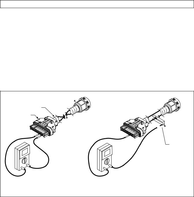
b.If the continuity check is good (0–2 Ohms resistance), remove the jumpers. Check the harness for shorts between wires and shorts-to-ground by performing the following (refer to Figure 4–2):
(1)At the ECU end of the harness, touch one VOM probe to one wire of the circuit being tested and touch the other probe to each terminal in the same connector, then touch the probe to chassis ground and to the transmission main housing. Do this for both wires in the circuit being tested.
(2)If at any time the VOM shows zero to low resistance, or the meter’s continuity beeper sounds, there is a short between the two points being probed — wire-to-wire or wire-to-ground. Isolate and repair the short.
TRANSMISSION CONNECTOR
WIRING HARNESS
ECU “T” CONNECTOR
 Wires shorted together
|
0 |
|
|
|
|
VOLT/OHM- |
|
|
– |
METER |
|
+ |
(VOM) |
||
|
|||
|
|
0 OHMS
Two wires have frayed and are shorted together. Continuity beeper of VOM will sound, or reading will go to zero Ohms when these two wires are probed with the VOM.


 Shorted to ground on metal frame rail
Ground to metal frame rail
0
– +
0 OHMS
Harness has been chafed and one or more
wires are shorted-to-ground. VOM continuity |
|
beeper will sound, or reading will go to zero |
|
Ohms when meter is probing between this wire |
|
and chassis ground. |
V03375 |
Figure 4–2. Short Between Wires or to Ground
4–2. CHECKING AT TRANSMISSION CONNECTOR AND THE INTERNAL HARNESS FOR OPENS, SHORTS BETWEEN WIRES, AND SHORTS-TO-GROUND
1.Disconnect the external wiring harness from the transmission.
2.Inspect the connectors. Any terminals which are corroded or dirty must be thoroughly cleaned.
3.If the connectors are clean and connected correctly, determine which wires in the harness to test. Use the diagnostic code system schematic to locate the wire terminals. For this example, Code 45 12 indicates a failure in the F solenoid circuit — wires 102-T1 and 120-T4 (refer to Figure 4–3 and 4–4).
4–2 |
Copyright © 2000 General Motors Corp. |
COMMERCIAL ELECTRONIC CONTROLS 2 (CEC 2) TROUBLESHOOTING MANUAL
WIRE CHECK PROCEDURES
The cleaning solvent must not be chlorine based, contain petroleum distillates, or conduct electricity. The cleaning solvent should evaporate quickly to prevent the
CAUTION:
possibility of condensation within the connectors. Always blow or shake any excess cleaner from the connector before assembling it to its mating connector or hardware. Cleaner trapped in the connector can affect the connector seal. (Refer to SIL 17-TR-94 for detailed information on the recommended cleaners.)
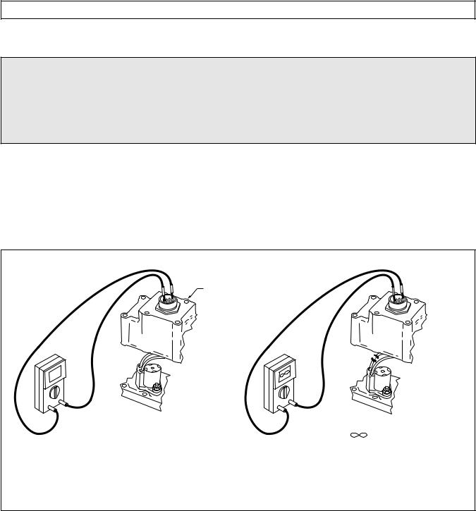
NOTE: Resistance of all solenoids (except J on 5610, 6610 models only) should be 12–24 Ohms. Solenoid J resistance on the 5610, 6610 should be 10–13 Ohms.
a.At the transmission main valve body connector, check the resistance of the F solenoid circuit. Resistance of the solenoid circuit should be 12–24 Ohms. No continuity in the circuit (infinite resistance) indicates an open in the internal harness, the feedthrough connector, or the solenoid coil. Locate and repair the open in the internal harness or replace the internal harness, replace the feedthrough connector, or replace the solenoid.
MAIN VALVE BODY
CONNECTOR
18 |
|
|
– |
– |
|
+ |
+ |
|
VOLT/OHM- |
|
|
METER |
|
|
(VOM) |
INFINITE ( ) OHMS |
|
12–24 OHMS |
||
Circuit does not have continuity due to a |
||
AT NORMAL OPERATING |
broken wire (open circuit). VOM reading is |
|
TEMPERATURE* |
very high (infinite ohms or OL–overlimit). |
|
Circuit has continuity. |
This could also be due to an open solenoid |
|
* Refer to Appendix J |
coil or bad connection. |
|
V06593 |
Figure 4–3. Checking Continuity
b.If the resistance check is good, check the harness for shorts between wires and to ground by performing the following (refer to Figure 4–4):
(1)At the transmission connector, touch one probe of the VOM to one wire of the circuit being tested and touch the other probe to each terminal in the connector and to chassis ground and the transmission main housing. Do this for both wires in the circuit being tested.
(2)If the VOM shows zero to low resistance, or the continuity beeper sounds, there is a short between the two points being probed, wire-to-wire or wire-to-ground. An indication of a short may be caused by a splice to the wire being checked. Check the wiring diagram in Appendix G for splice locations. If the short is not a splice, then isolate and repair the short.
Copyright © 2000 General Motors Corp. |
4–3 |
 Loading...