


DDEC IV APPLICATION AND INSTALLATION MANUAL
5 DDEC FEATURES
Section |
|
Page |
5.1 |
AIR COMPRESSOR CONTROL ............................................................. |
5-3 |
5.2 |
ANTI-LOCK BRAKE SYSTEMS .............................................................. |
5-9 |
5.3 |
CRUISE CONTROL ................................................................................ |
5-13 |
5.4CRUISE CONTROL FOR DRILLING/PUMPING APPLICATIONS WITH
|
OPTIONAL DUAL STATION CONTROL ................................................. |
5-21 |
5.5 |
DIAGNOSTICS ........................................................................................ |
5-23 |
5.6 |
EDM AND AIM ........................................................................................ |
5-27 |
5.7 |
ELECTRONIC FIRE COMMANDER ....................................................... |
5-31 |
5.8 |
ELECTRONIC SPEED SWITCH ............................................................. |
5-35 |
5.9 |
ENGINE BRAKE CONTROLS ................................................................ |
5-39 |
5.10 |
ENGINE PROTECTION .......................................................................... |
5-45 |
5.11 |
ENGINE RATINGS .................................................................................. |
5-57 |
5.12 |
ETHER START ........................................................................................ |
5-61 |
5.13 |
EXTERNAL ENGINE SYNCHRONIZATION ........................................... |
5-65 |
5.14 |
FAN CONTROL ....................................................................................... |
5-69 |
5.15 |
FUEL ECONOMY INCENTIVE ............................................................... |
5-83 |
5.16 |
GLOW PLUG CONTROLLER ................................................................. |
5-85 |
5.17 |
HALF ENGINE IDLE ............................................................................... |
5-89 |
5.18 |
IDLE SHUTDOWN TIMER AND VEHICLE POWER SHUTDOWN ........ |
5-91 |
5.19 |
IRIS ......................................................................................................... |
5-97 |
5.20 |
LOW GEAR TORQUE LIMITING ............................................................ |
5-105 |
5.21 |
MAINTENANCE ALERT SYSTEM .......................................................... |
5-107 |
5.22 |
MANAGEMENT INFORMATION PRODUCTS ........................................ |
5-131 |
All information subject to change without notice. (Rev. (Rev. 3/02)) |
5-1 |
7SA742 0203 Copyright © 2002 DETROIT DIESEL CORPORATION

DDEC FEATURES
5.23 |
MARINE CONTROLS ............................................................................. |
5-175 |
5.24 |
OPTIMIZED IDLE .................................................................................... |
5-179 |
5.25 |
OPTIMUM LOAD SIGNAL ...................................................................... |
5-185 |
5.26 |
OVERALL GOVERNOR GAIN ................................................................ |
5-187 |
5.27 |
PASSMART ............................................................................................. |
5-189 |
5.28 |
PASSWORDS ......................................................................................... |
5-193 |
5.29 |
PRESSURE SENSOR GOVERNOR ...................................................... |
5-197 |
5.30 |
PROGRESSIVE SHIFT ........................................................................... |
5-203 |
5.31 |
PULSE TO VOLTAGE MODULE ............................................................. |
5-209 |
5.32 |
TACHOMETER DRIVE ............................................................................ |
5-213 |
5.33 |
THROTTLE CONTROL/GOVERNORS ................................................... |
5-215 |
5.34 |
TRANSMISSION INTERFACE ................................................................ |
5-233 |
5.35 |
TRANSMISSION RETARDER ................................................................ |
5-253 |
5.36 |
VEHICLE SPEED LIMITING ................................................................... |
5-255 |
5.37 |
VEHICLE SPEED SENSOR ANTI-TAMPERING .................................... |
5-257 |
5-2 |
All information subject to change without notice. (Rev. (Rev. 3/02)) |
7SA742 0203 Copyright © 2002 DETROIT DIESEL CORPORATION

DDEC IV APPLICATION AND INSTALLATION MANUAL
5.1AIR COMPRESSOR CONTROL
Air Compressor Controlis an optional DDEC feature that allows DDEC to regulate engine speed and load/unload a valve in order to maintain a requested compressor outlet air pressure for air compressor applications.
The DDEC Air Compressor Control Feature is available with the following software releases:
DDEC III - Release 4.0 (only)
DDEC IV - all software versions (Release 20.0 or later)
5.1.1OPERATION
The ECM monitors the air outlet pressure while varying the engine speed and operating load/unload a valve. The valve will be opened or closed. The desired operating pressure may be varied by the operator, within limits preset by the OEM.
The ECM will activate the Air Compressor Governor Controls when the digital input “Air Compressor Load Switch” is grounded. Engine speed is governed based on the actual air compressor outlet pressure versus the desired output pressure. The Air Compressor Pressure Sensor provides a pressure signal to the ECM.
The engine response to various pressure conditions is listed in Table 5-1.
Pressure Set Point |
Result |
|
|
Current outlet pressure is below the pressure set |
Engine speed increases as required up to PTO |
point |
maximum speed* |
Pressure in the system continues to increase and |
The air compressor solenoid digital output is |
a threshold pressure is exceeded |
enabled† (opened) |
Current outlet pressure is above the pressure set |
Engine speed decreases as required down to the |
point |
minimum PTO speed. |
*The engine will continue to run at PTO maximumuntil the outlet pressure matches the sensor pressure.
†DDEC will open and close the loading valve as a function of pressure with hysteresis. When the pressure reaches a programmable limit above the pressure set point the DDEC digital output will be grounded. This output may be used to either open an air compressor vent or close the air inlet. Once the air pressure has dropped to a lower programmable limit, the digital output will be open circuited which will either close the vent
Table 5-1 Engine Operation with Air Compressor Controls
Each horsepower rating has an associated pressure range. Horsepower ratings are defined at time of order entry. The minimum and maximum pressure setting for each of the horsepower curves is set with the DDDL/DDR, Vehicle Electronic Programming System (VEPS), or DRS. The initial pressure set point is saved between ignition cycles.
Increase (Resume/Acceleration On)
Momentarily toggling and releasing the Increase Switch (grounding the "Resume/Acceleration On" digital input) increases set point pressure by 4% of the pressure range. Holding the switch in the increase position (grounding the digital input), will increase the set point pressure at a rate of two increments per second. Releasing the switch sets the compressor controls to the higher setting.
All information subject to change without notice. (Rev. (Rev. 3/02)) |
5-3 |
7SA742 0203 Copyright © 2002 DETROIT DIESEL CORPORATION

DDEC FEATURES
Decrease (Set/Coast On)
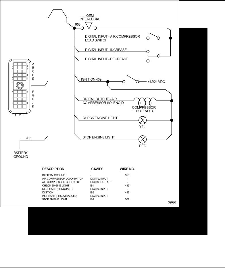
Momentarily toggling and releasing the decrease switch decreases set point pressure by 4% of the pressure range. See Figure 5-1. Holding the switch in the decrease position (grounding the digital input), will decrease the set point pressure at a rate of two increments per second. Releasing the switch sets the compressor controls to the lower setting.
Air Compressor Load Switch
Closing (grounding) the air compressor load switch digital input activates the air compressor control system. See Figure 5-1. Opening the air compressor load switch digital input deactivates the air compressor control system.
Air Compressor Solenoid
When the pressure reaches a programmable limit above the pressure set point the DDEC digital output will be grounded. This output may be used to either open an air compressor vent or close the air inlet. Once the air pressure has dropped to a lower programmable limit, the digital output will be open circuited which will either close the vent or open the air inlet.
Air Compressor Shutdown
DDEC will respond to a proprietary immediate engine shut down message sent over the SAE J1587/J1708 data link by the Electronic Display Module (EDM). This feature requires both an EDM and an Auxiliary Information Module (AIM); refer to section 5.6 for addition information on EDM and AIM.
Multiple Pressure Ratings
The pressure ranges are linked to the engine ratings. A pressure range can be associated with each rating. The maximum number of engine ratings and pressure ranges is three. Choosing the rating, with the DDR/DDDL or rating switches will automatically select the associated pressure range. The proper 6N4D group with multiple 6N4M groups must be specified. For additional information, contact your DDC Applications Engineer.
5-4 |
All information subject to change without notice. (Rev. (Rev. 3/02)) |
7SA742 0203 Copyright © 2002 DETROIT DIESEL CORPORATION
DDEC IV APPLICATION AND INSTALLATION MANUAL
5.1.2INSTALLATION
See Figure 5-1 for the Air Compressor Control Harness.
Figure 5-1 Air Compressor Control Harness
All information subject to change without notice. (Rev. (Rev. 3/02)) |
5-5 |
7SA742 0203 Copyright © 2002 DETROIT DIESEL CORPORATION

DDEC FEATURES
5.1.3PROGRAMMING REQUIREMENTS AND FLEXIBILITY
Air Compressor Controls must be specified at the time of engine order or added to the ECM calibration by Detroit Diesel Technical Service. An Application Code (6N4C) Group must be selected that is configured for Air Compressor Control at order entry or by contacting Detroit Diesel Technical Service.
The digital outputs and inputs listed in Table 5-2 are required for Air Compressor Controls and must be configured by order entry, VEPS, or the DRS.
Description |
Type |
Function Number |
|
|
|
|
|
Set/Coast On (Decrease) |
Digital Input |
20 |
|
|
|
|
|
Resume/Acceleration On |
Digital Input |
22 |
|
(Increase) |
|||
|
|
||
Air Compressor Load Switch |
Digital Input |
35 |
|
|
|
|
|
Air Compressor Solenoid |
Digital Output |
21 |
|
|
|
|
Table 5-2 Air Compressor Control Required Digital Inputs and Outputs
At order entry, the Application Code System (ACS) sets the default values for the parameters listed in Table 5-3. These parameters may be modified using either VEPS or DRS.
Parameter |
Description |
Choice/Display |
|
|
|
|
|
Air Compressor Integral Gain |
Integral Gain |
0-128 RPM/(PSI x SEC) |
|
|
|
|
|
Air Compressor Proportional Gain |
Proportional Gain |
0-128 RPM/PSI |
|
|
|
|
|
Air Compressor Pressure |
Percent Pressure Increment |
0-50% (of fuel scale pressure |
|
Increment |
range) |
||
|
Table 5-3 Air Compressor Control Parameters
Multiple pressure ratings can be selected with the use of rating switches. The proper 6N4D groups with multiple 6N4M groups must be specified at engine order or by Detroit Diesel Technical Service. The digital inputs listed in Table 5-4 are required.
Description |
Type |
Function Number |
|
|
|
Rating Switch #1 |
Digital Input |
12 |
|
|
|
Rating Switch #2 |
Digital Input |
13 |
|
|
|
Table 5-4 Multiple Pressure Ratings Required Digital Inputs
The VSG maximum and minimum RPM can be set with VEPS, DRS, DDR or DDDL as listed in Table 5-5.
5-6 |
All information subject to change without notice. (Rev. (Rev. 3/02)) |
7SA742 0203 Copyright © 2002 DETROIT DIESEL CORPORATION

DDEC IV APPLICATION AND INSTALLATION MANUAL
Parameter |
Description |
Choice/Display |
|
|
|
VSG Minimum RPM |
Sets the VSG minimum speed. |
Idle to VSG, Maximum RPM |
|
|
|
VSG Maximum RPM |
Sets the VSG maximum speed. |
VSG Minimum RPM to (Rated Speed |
|
|
+ LSG Droop) |
|
|
|
Table 5-5 Variable Speed Governor Maximum and Minimum RPM
The minimum and maximum pressure is set with the DDDL/DDR, DRS or VEPS as listed in Table 5-6. There is a minimum and maximum pressure setting for each of the horsepower curves.
Parameter |
Description |
Range |
|
|
|
|
|
|
Indicates the delta value above the current air |
|
|
LOAD PSI |
pressure set point that will initiate the air compressor |
0 to UNLOAD PSI |
|
|
governor to reload the system. |
|
|
|
Indicates the delta value above the current air |
|
|
UNLOAD PSI |
pressure set point that will initiate the air compressor |
LOAD PSI to 31 PSI |
|
|
governor to unload the system. |
|
|
MAX RAT#1 PSI |
Indicates the maximum allowable air pressure set |
MIN RAT#1 to 999 PSI |
|
point for engine rating #1 |
|||
|
|
||
MIN RAT#1 PSI |
Indicates the minimum allowable air pressure set |
0 to MAX RAT#1 |
|
point for engine rating #1. |
|||
|
|
||
MAX RAT #2 PSI |
Indicates the maximum allowable air pressure set |
MIN RAT#2 to 999 PSI |
|
point for engine rating #2. |
|||
|
|
||
MIN RAT#2 PSI |
Indicates the minimum allowable air pressure set |
0 to MAX RAT#2 |
|
point for engine rating #2. |
|||
|
|
||
MAX RAT#3 PSI |
Indicates the maximum allowable air pressure set |
MIN RAT#3 to 999 PSI |
|
point for engine rating #3. |
|||
|
|
||
MIN RAT #3 PSI |
Indicates the minimum allowable air pressure set |
0 to MAX RAT#3 |
|
point for engine rating #3. |
|||
|
|
Table 5-6 Air Compressor Parameters
5.1.4INTERACTION WITH OTHER FEATURES
Air Compressor Control may not be used with Cruise Control or the Pressure Sensor Governor. A proprietary immediate engine shut down message for immediate air compressor shutdown is sent over the SAE J1587/J1708 data link by the EDM. This feature requires both an EDM and an AIM; refer to section 5.6 for addition information on EDM and AIM.
All information subject to change without notice. (Rev. (Rev. 3/02)) |
5-7 |
7SA742 0203 Copyright © 2002 DETROIT DIESEL CORPORATION

DDEC FEATURES
THIS PAGE INTENTIONALLY LEFT BLANK
5-8 |
All information subject to change without notice. (Rev. (Rev. 3/02)) |
7SA742 0203 Copyright © 2002 DETROIT DIESEL CORPORATION

DDEC IV APPLICATION AND INSTALLATION MANUAL
5.2ANTI-LOCK BRAKE SYSTEMS
Anti-lock Brake Systems (ABS) are electronic systems that monitor and control wheel speed during braking. The systems are compatible with standard air brake systems. The system monitors wheel speed at all times, and controls braking during emergency situations. Vehicle stability and control are improved by reducing wheel lock during braking.
5.2.1OPERATION
The ECM transmits engine data via SAE J1587, SAE J1922, or SAE J1939. Anti-lock brake systems monitor data on one or more of these communication links. In the event that an excessive wheel spin is detected, the ECM receives a message from the ABS requesting a 0% output torque limit. The message is transmitted on SAE J1922 or SAE J1939.
SAE J1922 and SAE J1939 both implement the same message set. The difference being hardware and performance. SAE J1922 transmits and receives data at 9.6 K baud while SAE J1939 transmits/receives data at 250 K baud. SAE J1939 has a much higher bit rate so messages reach their destination very quickly nearly eliminating the latency found with SAE J1922.
SAE J1922 is enabled on all DDEC IV ECMs. SAE J1939 is enabled on all DDEC IV ECMs (Release 24.0 or later). ECMs prior to Release 24.0 must be configured if SAE J1939 is required.
See Figure 5-2 and Figure 5-3 for interface with Meritor/WABCO and Bosch respectively.
All information subject to change without notice. (Rev. (Rev. 3/02)) |
5-9 |
7SA742 0203 Copyright © 2002 DETROIT DIESEL CORPORATION

DDEC FEATURES
Figure 5-2 Meritor/WABCO ABS/ATC Interface
5-10 |
All information subject to change without notice. (Rev. (Rev. 3/02)) |
7SA742 0203 Copyright © 2002 DETROIT DIESEL CORPORATION
DDEC IV APPLICATION AND INSTALLATION MANUAL
Figure 5-3 Bosch ABS/ATC Interface
All information subject to change without notice. (Rev. (Rev. 3/02)) |
5-11 |
7SA742 0203 Copyright © 2002 DETROIT DIESEL CORPORATION

DDEC FEATURES
THIS PAGE INTENTIONALLY LEFT BLANK
5-12 |
All information subject to change without notice. (Rev. (Rev. 3/02)) |
7SA742 0203 Copyright © 2002 DETROIT DIESEL CORPORATION

DDEC IV APPLICATION AND INSTALLATION MANUAL
5.3CRUISE CONTROL
Cruise Control is available with any DDEC engine. Cruise Control will operate in either Engine or Vehicle Speed Mode and maintain a targeted speed (MPH or RPM) by increasing or decreasing fueling. The targeted speed can be selected and adjusted with dash-mounted switches. Up to five digital inputs are required (four for automatic transmission) for Cruise Control operation and a digital output is optional (refer to section 4.1.1 for additional information on digital inputs). A Vehicle Speed Sensor (VSS) is required for Vehicle Speed Cruise Control.
5.3.1OPERATION
There are two types of Cruise Control: Engine Speed Cruise Control and Vehicle Speed Cruise Control.
Engine Speed Cruise Control
Power is varied under Engine Speed Cruise Control to maintain constant engine speed. Vehicle speed will vary depending on powertrain components. Engine Speed Cruise Control does not need a VSS. Engine Speed Cruise Control cannot be used with automatic transmissions.
Vehicle Speed Cruise Control
Vehicle Speed Cruise is enabled when "Enable Cruise" and a Vehicle Speed Sensor (VSS) are installed. Engine speed and power are varied under Vehicle Speed Cruise Control to maintain the set vehicle speed. The maximum Cruise Control speed cannot exceed the programmed maximum Vehicle Speed Limit (when programmed). The vehicle speed must be above 20 MPH and the engine speed above 1,100 RPM (1,000 RPM for on-highway 1999 model year or later engines) to set Cruise Control.
This type of Cruise Control is required when either of the following conditions exists:
Vehicle Speed Limiting -- Vehicle Speed Cruise Control is mandatory if the vehicle speed limit is programmed and Cruise Control is desired. This will prevent the ECM from fueling the engine at speeds greater than the vehicle speed limit.
Automatic Transmissions -- Vehicle Speed Cruise Control must be selected if the vehicle is equipped with an automatic transmission. This will ensure proper transmission upshifts while in Cruise Control. Refer to the transmission manufacturer's manual for more information and see the Vehicle Interface Harness schematic.
Cruise control can be overridden at any time with the foot pedal if the vehicle is not operating at the programmed Vehicle speed Limit.
Smart Cruise
The Eaton® Smart Cruise™ system will send a "heart beat" message on the SAE J1939 Data Link. Manual Cruise Control and Smart Cruise will be disabled if the message is not received over the data link or the message indicates that there is a failure in Smart Cruise. To regain manual control, the driver must toggle the Cruise Master Switch twice within 10 seconds.
Eaton® and Smart Cruise™ trademarks of the Eaton Corporation.
All information subject to change without notice. (Rev. (Rev. 3/02)) |
5-13 |
7SA742 0203 Copyright © 2002 DETROIT DIESEL CORPORATION

DDEC FEATURES
This feature is available with Release 27.0 or later. Smart Cruise must be configured by VEPS (Release 27.0 or later), WinVeps (Release 2.0 or later) or the DRS. For additional information on Smart Cruise, contact Eaton Corporation.
Cruise Enable
Cruise Control is enabled, but not active when the Cruise Control Enable digital input is switched to battery ground.
Set / Coast On
Set: |
Cruise Speed is set by momentarily contacting the switch to the ON position |
|
(switching the digital input to battery ground). Cruise Control will become |
|
active and maintain the engine or vehicle speed present at the time. |
Coast: When Cruise Control is active, the Set/Coast input can be used to reduce power and speed by toggling the switch. Momentarily toggling and releasing the Set/Coast switch will decrease the set point by 1 MPH increments for Vehicle Speed Cruise Control and 25 RPM increments for Engine Speed Cruise Control. Holding the Set/Coast will decrease the set point by 1 MPH per second (Vehicle Speed CC) or 25 RPM per seconds (Engine Speed CC). When released the Cruise Control set point will be at the new speed.
Resume / Accel On
Resume: If Cruise Control has been disabled with the service brake or the clutch switch,
|
momentary contact to the ON position (switching the input to battery ground) |
|
restores the previously set cruise speed. |
Accel: |
When Cruise Control is active, the Resume/Accel input can be used to increase |
|
power and speed by toggling the switch. Momentarily toggling and releasing the |
|
Resume/Accel switch will increase the set point by 1 MPH increments for Vehicle |
|
Speed Cruise Control and 25 RPM increments for Engine Speed Cruise Control. |
|
Holding the Resume/Accel will increase the set point by 1 MPH per second |
|
(Vehicle Speed CC) or 25 RPM per seconds (Engine Speed CC). When released |
|
the Cruise Control set point will be at the new speed. |
5-14 |
All information subject to change without notice. (Rev. (Rev. 3/02)) |
7SA742 0203 Copyright © 2002 DETROIT DIESEL CORPORATION

DDEC IV APPLICATION AND INSTALLATION MANUAL
Clutch Released (Manual Transmissions)
This input indicates that the clutch is released and is used for suspending Cruise Control and Auto Resume.
When the clutch is released, the input is at battery ground. Cruise Control is suspended if the clutch is depressed once. If the clutch is depressed twice within three seconds, Cruise Control is automatically resumed.
NOTE:
When engine brake is configured and auto resume is enabled, the first time the clutch is depressed to suspend Cruise Control, the engine brakes will be delayed for three seconds.
The digital input logic for the Clutch Switch disables Cruise Control in the unlikely event of a broken clutch switch wire.
Service Brake Released (Automatic and Manual Transmissions)
This input indicates that the brake is released when switched to battery ground. If the brake is activated, then the input is not grounded and Cruise Control is suspended. Cruise Control is resumed by using the Resume/Accel Switch.
The input logic for the Brake Switch disables Cruise Control in the unlikely event of a broken brake switch wire.
5.3.2INSTALLATION
The following is a list of switches that are required for Cruise Control operation.
Cruise Enable Switch
Brake Switch
Clutch Switch -- optional for automatic transmissions
Set/Coast Switch
Resume/Accel Switch
Cruise Active Light -- optional
All information subject to change without notice. (Rev. (Rev. 3/02)) |
5-15 |
7SA742 0203 Copyright © 2002 DETROIT DIESEL CORPORATION
DDEC FEATURES
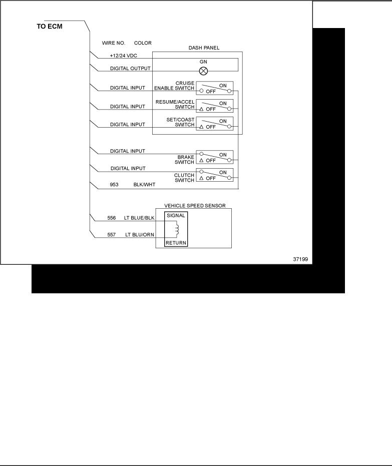
See Figure 5-4 for a diagram of the Cruise Control circuit.
Figure 5-4 Cruise Control Circuit
5-16 |
All information subject to change without notice. (Rev. (Rev. 3/02)) |
7SA742 0203 Copyright © 2002 DETROIT DIESEL CORPORATION

DDEC IV APPLICATION AND INSTALLATION MANUAL
5.3.3PROGRAMMING REQUIREMENTS AND FLEXIBILITY
To configure an engine for Cruise Control, the digital inputs, output and VSS settings listed in Table 5-7 must be selected either with the Vehicle Electronic Programming System (VEPS), the DDEC Reprogramming System (DRS) or on engine order entry. The required and optional digital inputs and outputs are listed in Table 5-7.
Description |
Type |
Function Number |
|
|
|
|
|
Service Brake Released |
Digital Input |
17 |
|
|
|
|
|
Set/Coast |
Digital Input |
20 |
|
|
|
|
|
Resume/Accel |
Digital Input |
22 |
|
|
|
|
|
Cruise Control Enable |
Digital Input |
23 |
|
|
|
|
|
Clutch Released |
Digital Input |
18 |
|
(required for manual transmissions) |
|||
|
|
||
Cruise Control Active Light |
Digital Output |
11 |
|
(optional for Cruise Control) |
|||
|
|
Table 5-7 Cruise Control Related Digital Input and Output Signals
A Vehicle Speed Sensor must be configured for Vehicle Speed Cruise Control. Refer to section 3.14.25, "Vehicle Speed Sensor," for additional information.
If Eaton Smart Cruise is installed on the vehicle, the feature as listed in Table 5-8 must be enabled by VEPS or DRS.
Parameter |
Description |
Choice |
|
|
|
|
|
Adaptive Cruise Control |
Enables or disables the Smart Cruise Control feature. |
YES, NO |
|
(Smart Cruise) |
|||
|
|
||
|
|
|
Table 5-8 Smart Cruise Parameter
The Cruise Control parameters listed in Table 5-9 can be set by order entry, DDR, DDDL, the DRS, or VEPS.
All information subject to change without notice. (Rev. (Rev. 3/02)) |
5-17 |
7SA742 0203 Copyright © 2002 DETROIT DIESEL CORPORATION

DDEC FEATURES
Parameter |
Description |
Range |
|
|
|
|
|
CRUISE CONTROL |
Enables or disables the vehicle speed Cruise |
YES, NO |
|
Control feature. |
|||
|
|
||
MIN CRUISE SPEED |
Sets the maximum cruise speed in MPH or KPH. |
20 MPH to MAX |
|
CRUZ SPD |
|||
|
|
||
|
|
|
|
|
|
MIN CRUZ to Vehicle |
|
MAX CRUISE MPH or KPH |
Sets the maximum cruise speed in MPH or KPH. |
Speed Limit or 127 mph |
|
|
|
if VSL = NO |
|
|
|
|
|
AUTO RESUME |
Enables or disables the automatic Cruise Control |
YES, NO |
|
set speed resume feature. |
|||
|
|
||
CRUISE SWITCH VSG |
Enables or disables the cruise switch VSG set |
YES, NO |
|
speed feature. |
|||
|
|
||
INITIAL VSG SET SPEED |
Sets the cruise switch VSG initial set speed. |
VSG MIN RPM to |
|
VSG MAX RPM |
|||
|
|
||
|
|
|
|
RPM INCREMENT |
Sets the cruise switched VSG RPM increment. |
1 to 255 RPM |
|
|
|
|
|
CRUISE/ENGINE BRAKE |
Enables or disables the feature that allows the |
|
|
engine brake to be used while on Cruise Control |
YES, NO |
||
FEATURE |
|||
if the vehicle exceeds the cruise set speed. |
|
||
|
|
||
|
Sets the additional speed before the engine |
|
|
CRUISE/ENGINE BRAKE |
brake is applied to slow down the vehicle. The |
|
|
engine brake is activated at low level unless the |
0 to 10 MPH |
||
ACTIVATION SPEED |
|||
operator has turned off the engine brakes with |
|
||
|
|
||
|
the dash board switches. |
|
|
ENG BRAKE INCREMENT |
Sets the additional incremental speed that must |
|
|
be reached before the engine brake will activate |
1 to 5 MPH |
||
MPH or KPH |
|||
the medium and/or high level of retardation. |
|
||
|
|
||
|
|
|
|
|
Sets the vehicle speed above which a diagnostic |
|
|
MAX OVERSPEED LIMIT |
code will be logged if the driver fuels the engine |
0 to 127 MPH |
|
and exceeds this limit. Entering a 0 will disable |
|||
|
|
||
|
this option. |
|
|
|
Sets the vehicle speed above which a diagnostic |
|
|
MAX SPEED NO FUEL |
code will be logged if the vehicle reaches this |
0 to 127 MPH |
|
speed without fueling the engine. Entering a 0 |
|||
|
|
||
|
will disable this option. |
|
Table 5-9 Cruise Control Parameters
5.3.4DIAGNOSTICS
Two faults (SID 216 FMI 14 and PID 86 FMI 14) will be logged simultaneously if Smart Cruise is enabled and the data is not being received, the received data is bad or the Smart Cruise unit has been removed.
If these faults are received in addition to an SAE J1939 Data Link failure (SID 231 FMI 12), then the problem is with the SAE J1939 Data Link itself.
5-18 |
All information subject to change without notice. (Rev. (Rev. 3/02)) |
7SA742 0203 Copyright © 2002 DETROIT DIESEL CORPORATION

DDEC IV APPLICATION AND INSTALLATION MANUAL
5.3.5INTERACTION WITH OTHER FEATURES
The Cruise Control logic is also used with the DDEC Pressure Sensor Governor in fire trucks. Both systems cannot be configured on the same engine. Refer to section 5.29 for more information on the Pressure Sensor Governor. DDEC can be configured to allow the engine brakes to activate during Cruise Control operation.
NOTE:
Cruise Control maximum speed cannot exceed the vehicle speed limit.
All information subject to change without notice. (Rev. (Rev. 3/02)) |
5-19 |
7SA742 0203 Copyright © 2002 DETROIT DIESEL CORPORATION

DDEC FEATURES
THIS PAGE INTENTIONALLY LEFT BLANK
5-20 |
All information subject to change without notice. (Rev. (Rev. 3/02)) |
7SA742 0203 Copyright © 2002 DETROIT DIESEL CORPORATION
DDEC IV APPLICATION AND INSTALLATION MANUAL
5.4CRUISE CONTROL FOR DRILLING/PUMPING APPLICATIONS WITH OPTIONAL DUAL STATION CONTROL
Cruise control for drilling/pumping applications is an optional DDEC feature that allows the setting of a targeted engine speed and a easy return to the targeted speed from idle.
For example, petroleum mud pumps are used to supply fluid to a drilling bit when a well is being drilled. The operator will carefully adjust engine speed until he/she achieves the desired pumping rate. The optimum speed will vary from job to job. The operator will continue until a new section of drilling pipe must be added. At that point, the engine must be brought back to idle and the transmission or clutch disengaged while new pipe is threaded in place. The operator can then bring the engine back up to operating speed and continue the drilling and pumping operation.
5.4.1OPERATION
This feature allows the operator to set an engine speed during the drilling and pumping process, drop to idle speed, and then return to the original speed. Returning to the original set speed is desirable since it has been carefully dialed in by the operator and is ideal for the particular job. The Engine Speed Cruise Control feature would work to provide the desired engine set speed for the pumping operation, but it is not configured to resume speed from engine idle.
This process operates as follows:
1.Start the engine, idle, and warm up.
2.Engage the ALT_MIN_VSG Switch - engine goes to ALT_MIN_VSG speed (e.g. 650 rpm).
3.Engage the Cruise Enable Switch.
4.Adjust the hand throttle to the desired speed, e.g. 1700 rpm.
5.Engage set/coast - sets speed to the desired speed, 1700 rpm.
6.Adjust the hand throttle back to idle position.
7.When the need to add pipe arises, engage the brake switch. The engine drops to 650 rpm.
8.When ready to continue, engage Resume/Accel and the speed returns to 1700 rpm.
All information subject to change without notice. (Rev. (Rev. 3/02)) |
5-21 |
7SA742 0203 Copyright © 2002 DETROIT DIESEL CORPORATION

DDEC FEATURES
5.4.2PROGRAMMING REQUIREMENTS & FLEXIBILITY
The hardware and software configuration include the proper 6N4C group for VSG engine governing such as 06N04C0720 and customer selectable parameters.
The customer selectable parameters settings are listed in Table 5-10.
Parameter |
Description |
Setting |
|
|
|
|
|
Cruise Control Enable |
Enables the engine speed cruise control feature. |
YES |
|
|
|
|
|
Alternate Minimum VSG |
Sets the Alternate Minimum VSG speed |
650 RPM |
|
(set above the idle speed) |
|||
|
|
Table 5-10 Customer Selectable Parameters
The digital inputs listed in Table 5-11 must be programmed.
Description |
|
Type |
Function Number |
|
|
|
|
|
|
Cruise Enable |
|
Digital Input |
23 |
|
|
|
|
|
|
Set/Coast |
|
Digital Input |
20 |
|
|
|
|
|
|
Resume/Accel |
|
Digital Input |
22 |
|
|
|
|
|
|
Service Brake |
|
Digital Input |
17 |
|
|
|
|
|
|
Alt Min VSG |
|
Digital Input |
16 |
|
|
|
|
|
|
Table 5-11 |
Digital Inputs |
|
|
|
5.4.3DUAL STATION CONTROLS
This feature will also work with dual control stations. The operator has the capability of starting the engine at Station 1 mounted near the engine, follow the operation procedure above, and while at the desired operating speed, switch to throttle Station 2 and adjust engine speed remotely, if desired. The operator could then switch back to Station 1 when pipe was to be added.
For dual station controls, the digital inputs listed in Table 5-10 are required in addition to the digital inputs listed in Table 5-12.
Description |
Type |
Function Number |
|
|
|
VSG Station Change |
Digital Input |
33 |
|
|
|
VSG Station Change Complement |
Digital Input |
34 |
|
|
|
Table 5-12 Additional Dual Station Control Digital Inputs
For additional installation information on VSG Dual Station Controls, refer to section, 4.31 "Throttle Controls/Governors".
5-22 |
All information subject to change without notice. (Rev. (Rev. 3/02)) |
7SA742 0203 Copyright © 2002 DETROIT DIESEL CORPORATION
DDEC IV APPLICATION AND INSTALLATION MANUAL
5.5DIAGNOSTICS
Diagnostics is a standard feature of the DDEC system. The purpose of this feature is to provide information for problem identification and problem solving in the form of a code. The ECM continuously performs self diagnostic checks and monitors the other system components. Information for problem identification and problem solving is enhanced by the detection of faults, retention of fault codes and separation of active from inactive codes.
5.5.1OPERATION
The engine-mounted ECM includes control logic to provide overall engine management. System diagnostic checks are made at ignition on and continue throughout all engine operating modes.
Sensors provide information to the ECM regarding various engine and vehicle performance characteristics. The information is used to regulate engine and vehicle performance, provide diagnostic information, and activate the engine protection system.
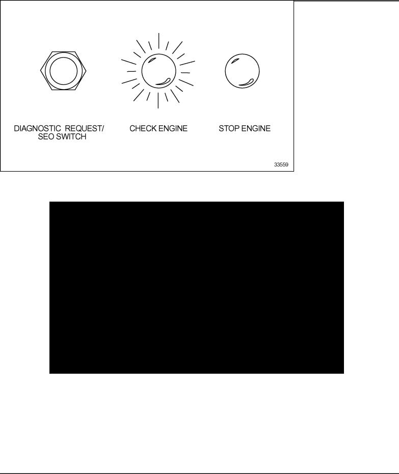
Instrument panel warning lights (see Figure 5-5), the Check Engine Light (CEL) and the Stop Engine Light (SEL), warn the engine operator. The CEL is an amber light and the SEL is a red light.
Figure 5-5 Typical Diagnostic Request/SEO Switch and Warning Lights
All information subject to change without notice. (Rev. (Rev. 3/02)) |
5-23 |
7SA742 0203 Copyright © 2002 DETROIT DIESEL CORPORATION

DDEC FEATURES
The CEL is illuminated and a code is stored if an electronic system fault occurs. This indicates the problem should be diagnosed as soon as possible. The ECM illuminates the CEL and SEL and stores a malfunction code if a potentially engine damaging fault is detected. These codes can be accessed in one of four ways:
Using the Diagnostic Data Reader (DDR)
Flashing the CEL and SEL with the Diagnostic Request Switch (may be combined with Stop Engine Override switch, see Figure 5-5)
Using the Detroit Diesel Diagnostic Link™ (DDDL) PC software package
By ProDriver® , Electronic Fire Commander™, Ele ctronic Display Module (EDM), or other display
There are two types of diagnostic codes:
An active code - a fault present at the time when checking for codes
An inactive code - a fault which has previously occurred; inactive codes are logged into the ECM and time stamped with the following information:
First occurrence of each diagnostic code in engine hours
Last occurrence of each diagnostic code in engine hours
Total time in seconds that the diagnostic code was active
5-24 |
All information subject to change without notice. (Rev. (Rev. 3/02)) |
7SA742 0203 Copyright © 2002 DETROIT DIESEL CORPORATION
DDEC IV APPLICATION AND INSTALLATION MANUAL
Diagnostic Request Switch
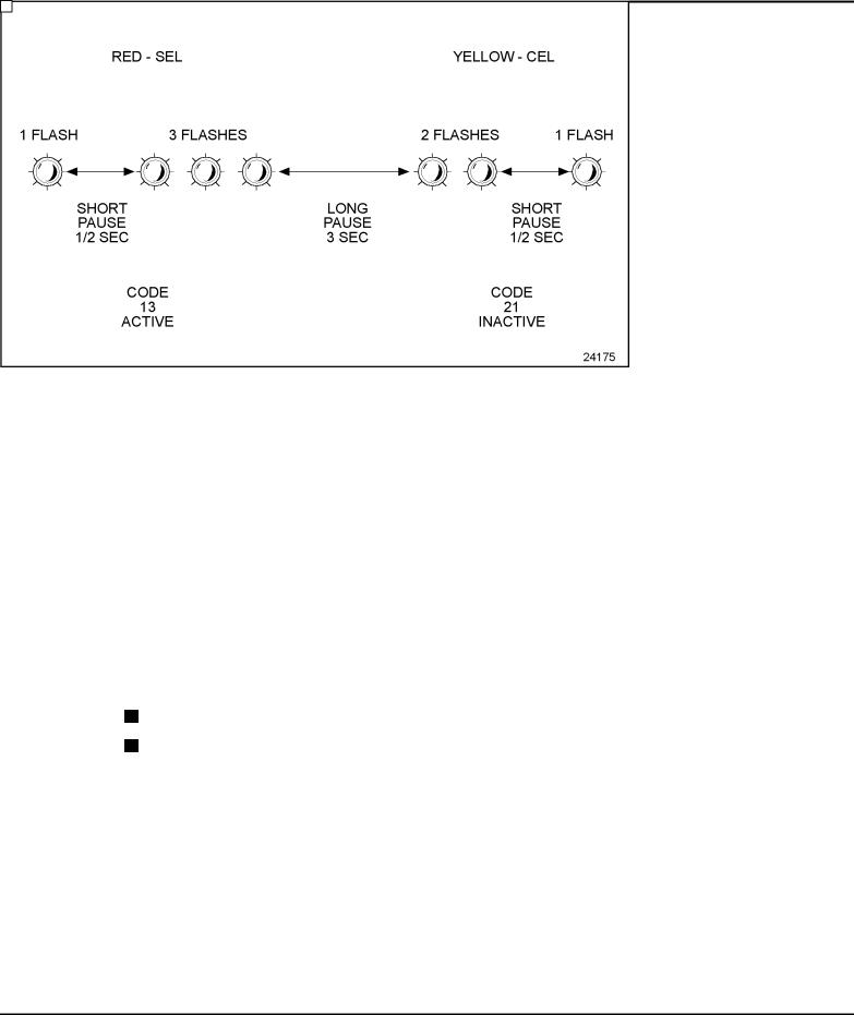
The Diagnostic Request Switch is used to activate the CEL/SEL to flash codes. Active codes are flashed on the SEL and inactive codes are flashed on the CEL (see Figure 5-6). Inactive codes are flashed in numerical order, active codes are flashed in the order received, most recent to least recent. The Diagnostic Request Switch can also be used as the Stop Engine Override (SEO) Switch. The codes are flashed out of the ECM connected to the switch.
|
|
Figure 5-6 |
Flash Codes |
NOTE:
For multi-ECM installations, the Diagnostic Request Switch and SEO are combined on the master ECM. All receiver ECMs have a separate Diagnostic Request Switch.
The Diagnostic Request Switch is used to flash codes in the following circumstances:
The engine is not running and ignition is ON
The engine is idling
In both circumstances, activating and holding the Diagnostic Request Switch will flash out the diagnostic codes.
All information subject to change without notice. (Rev. (Rev. 3/02)) |
5-25 |
7SA742 0203 Copyright © 2002 DETROIT DIESEL CORPORATION

DDEC FEATURES
Diagnostic Request Switch/Stop Engine Override
If no separate Diagnostic Request Switch is configured, the SEO Switch serves as both a Diagnostic Request Switch and an SEO Switch.
The Diagnostic Request/Stop Engine Override Switch is used to flash codes in the following circumstances:
The engine is not running and ignition is on
The engine is idling
In both circumstances, activating and releasing the switch will flash out the diagnostic codes; activating and releasing the switch a second time will stop the ECM from flashing the diagnostic codes. Codes will also cease flashing if the engine is no longer at idle. The codes are flashed out of the ECM connected to the switch.
NOTE:
For multi-ECM installations, the Diagnostic Request Switch and SEO Switch are combined on the master ECM. All receiver ECMs have a separate Diagnostic Request Switch.
5.5.2DEFINITIONS AND ABBREVIATIONS
Parameter Identification Character (PID): A PID is a single byte character used in SAE J1587 messages to identify the data byte(s) that follow. PIDs in the range 0-127 identify single byte data, 128-191 identify double byte data, and 192-253 identify data of varying length.
Subsystem Identification Character (SID): A SID is a single byte character used to identify field-repairable or replaceable subsystems for which failures can be detected or isolated. SIDs are used in conjunction with SAE standard diagnostic codes defined in SAE J1587 within PID 194.
Failure Mode Identifier (FMI): The FMI describes the type of failure detected in the subsystem and identified by the PID or SID. The FMI and either the PID or SID combine to form a given diagnostic code defined in SAE J1587 within PID 194.
Flashing Codes: Provides a two digit number (see Figure 5-6). This code may cover several specific faults. It is provided to advise the operator of the general severity of the fault so the operator can decide if engine operation can continue without damaging the engine.
Refer to Appendix A for a list of codes, the code number when flashed, the SAE J1587 number and a description of each code.
5-26 |
All information subject to change without notice. (Rev. (Rev. 3/02)) |
7SA742 0203 Copyright © 2002 DETROIT DIESEL CORPORATION
DDEC IV APPLICATION AND INSTALLATION MANUAL
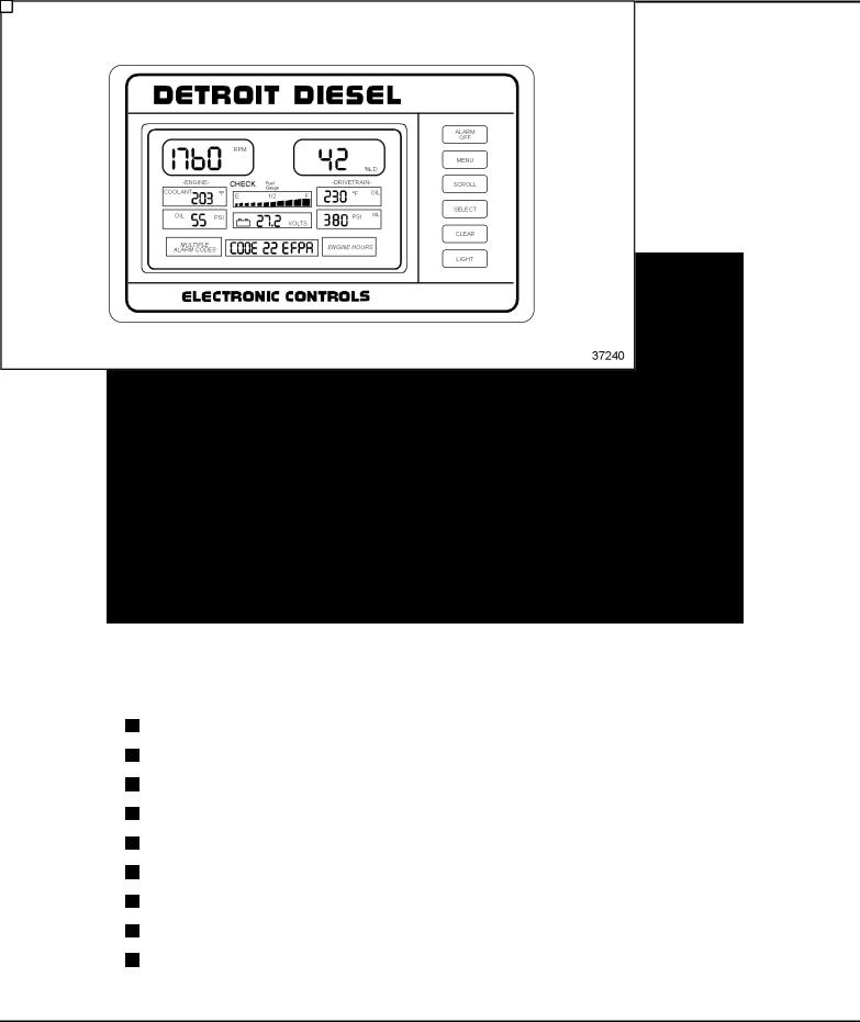
5.6EDM AND AIM
The Construction and Industrial Electronic Display Module (EDM) and Auxiliary Information Module (AIM) are the two components which comprise the Detroit Diesel Construction and Industrial Electronic Display system for engine and equipment parameters.
5.6.1OPERATION
The EDM (see Figure 5-7) may be used alone to display engine parameters or in conjunction with the AIM to display additional equipment parameters. AIM cannot be used without the EDM.
Figure 5-7 Electronic Display Module
The EDM will display the following parameters at all times if the sensor is installed on the equipment:
Engine RPM
Engine Coolant or Oil Temperature
(Oil Temperature only when coolant temperature is unavailable from the ECM)
Engine Oil Pressure
ECM Battery Voltage or Auxiliary Current (Requires AIM) - (Battery Voltage display)
Vehicle Speed or Auxiliary Pump Pressure or Engine Load
Equipment Temperature or Pressure (Requires AIM)
Equipment Temperature or Pressures (Requires AIM) or Engine Turbo Boost Pressure
Fuel Level (Requires AIM)
All information subject to change without notice. (Rev. (Rev. 3/02)) |
5-27 |
7SA742 0203 Copyright © 2002 DETROIT DIESEL CORPORATION
DDEC FEATURES
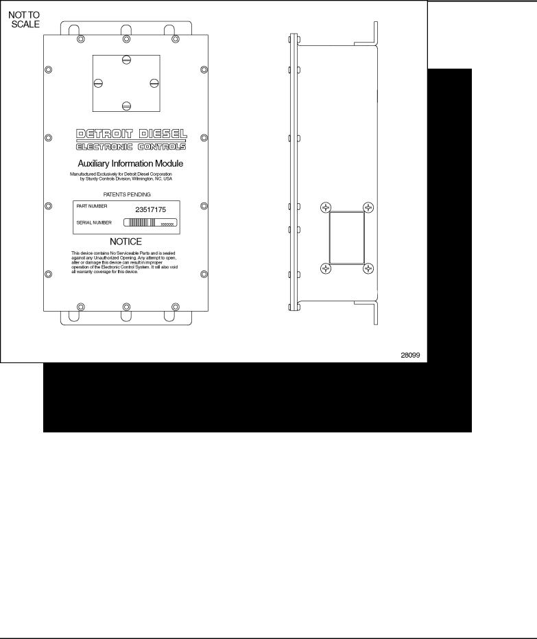
Check and Stop Indicators
The AIM (see Figure 5-8) is used in conjunction with the EDM to display additional equipment parameters.
Figure 5-8 Auxiliary Interface Module
5.6.2INSTALLATION
For information on installing the Construction and Industrial EDM and AIM refer to the
Construction & Industrial EDM and AIM Installation and Troubleshooting manual (7SA801).
5.6.3PROGRAMMING REQUIREMENTS AND FLEXIBILITY
Refer to Construction & Industrial EDM and AIM Installation and Troubleshooting manual (7SA801).
5-28 |
All information subject to change without notice. (Rev. (Rev. 3/02)) |
7SA742 0203 Copyright © 2002 DETROIT DIESEL CORPORATION

DDEC IV APPLICATION AND INSTALLATION MANUAL
5.6.4INTERACTION WITH OTHER FEATURES
DDEC installations equipped with both the EDM and AIM may initiate engine shutdowns based on equipment parameters. The shutdown option include the standard 30 second shutdown as well as an option for an immediate engine shutdown.
5.6.5DIAGNOSTICS
Refer to the Construction & Industrial EDM and AIM Installation and Troubleshooting manual (7SA801).
All information subject to change without notice. (Rev. (Rev. 3/02)) |
5-29 |
7SA742 0203 Copyright © 2002 DETROIT DIESEL CORPORATION

DDEC FEATURES
THIS PAGE INTENTIONALLY LEFT BLANK
5-30 |
All information subject to change without notice. (Rev. (Rev. 3/02)) |
7SA742 0203 Copyright © 2002 DETROIT DIESEL CORPORATION
 Loading...