


Mechanic’s Tips |
3000 and 4000 |
Product Families |
MT3004EN |

Mechanic’s
Tips
2006 MARCH
MT3004EN
Allison Transmission
Allison WTEC III Controls
(Except 3000 Product Family 7-Speed)
3000 Product Family
4000 Product Family
Allison Transmission, Inc.
P.O. Box 894 Indianapolis, Indiana 46206-0894
www.allisontransmission.com
Printed in USA |
Copyright © 2007 Allison Transmission, Inc. |
NOTES
2
TABLE OF CONTENTS
SECTION I |
INTRODUCTION |
|
|
1±1 |
ABOUT THIS MANUAL . . . . . . . . . . . . . . . . . . . . . . . . . . . . . . . |
7 |
|
SECTION II |
PREVENTIVE MAINTENANCE |
|
|
2±1 |
PERIODIC INSPECTION AND CARE . . . . . . . . . . . . . . . . . . . . . . |
20 |
|
2±2 IMPORTANCE OF PROPER TRANSMISSION FLUID LEVEL . . . . . . . |
20 |
||
2±3 |
TRANSMISSION FLUID TEST . . . . . . . . . . . . . . . . . . . . . . . . . . . |
21 |
|
2±4 |
KEEPING FLUID CLEAN . . . . . . . . . . . . . . . . . . . . . . . . . . . . . . |
27 |
|
2±5 |
FLUID RECOMMENDATIONS . . . . . . . . . . . . . . . . . . . . . . . . . . . |
27 |
|
2±6 TRANSMISSION FLUID AND FILTER CHANGE INTERVALS . . . . . . |
28 |
||
2±7 |
TRANSMISSION FLUID CONTAMINATION . . . . . . . . . . . . . . . . . . |
32 |
|
2±8 |
TRANSMISSION FLUID AND FILTER CHANGE PROCEDURE . . . . . |
35 |
|
2±9 |
FLUID LEAK DIAGNOSIS . . . . . . . . . . . . . . . . . . . . . . . . . . . . . |
37 |
|
2±10 |
BREATHER . . . . . . . . . . . . . . . . . . . . . . . . . . . . . . . . . . . . . . |
40 |
|
2±11 |
TROUBLESHOOTING . . . . . . . . . . . . . . . . . . . . . . . . . . . . . . . |
40 |
|
2±12 TRANSMISSION STALL TEST AND NEUTRAL COOL-DOWN |
|
||
|
CHECK . . . . . . . . . . . . . . . . . . . . . . . . . . . . . . . . . . . . . . . . . |
45 |
|
SECTION III |
REMOVING TRANSMISSION |
|
|
3±1 |
DRAINING TRANSMISSION . . . . . . . . . . . . . . . . . . . . . . . . . . . . |
51 |
|
3±2 |
DISCONNECTING CONTROLS . . . . . . . . . . . . . . . . . . . . . . . . . . |
51 |
|
3±3 UNCOUPLING FROM DRIVELINE, ENGINE, AND VEHICLE . . . . . . |
52 |
||
3±4 |
REMOVING THE TRANSMISSION . . . . . . . . . . . . . . . . . . . . . . . . |
53 |
|
3±5 REMOVING OUTPUT FLANGE OR YOKE . . . . . . . . . . . . . . . . . . . |
53 |
||
SECTION IV |
TRANSMISSION PREPARATION |
|
|
4±1 |
INSPECTING INPUT COMPONENTS . . . . . . . . . . . . . . . . . . . . . . |
55 |
|
4±2 INSTALLING OUTPUT FLANGE OR YOKE . . . . . . . . . . . . . . . . . . |
55 |
||
4±3 |
INSTALLING PTO . . . . . . . . . . . . . . . . . . . . . . . . . . . . . . . . . . . |
56 |
|
4±4 INSTALLING FILL TUBE AND SEAL . . . . . . . . . . . . . . . . . . . . . . |
57 |
||
4±5 |
INSPECTING PLUGS AND OPENINGS . . . . . . . . . . . . . . . . . . . . . |
58 |
|
3
SECTION V PREPARING VEHICLE FOR TRANSMISSION INSTALLATION
5±1 |
ENGINE, TRANSMISSION ADAPTATION REQUIREMENTS . . . . . . . |
59 |
5±2 |
CHECKING FLEXPLATE DRIVE ASSEMBLY . . . . . . . . . . . . . . . . . |
62 |
5±3 |
CHASSIS AND DRIVELINE INSPECTION . . . . . . . . . . . . . . . . . . . |
63 |
5±4 |
COOLER, FILTER, AND LINES . . . . . . . . . . . . . . . . . . . . . . . . . . |
64 |
5±5 |
INSPECTING CONTROLS . . . . . . . . . . . . . . . . . . . . . . . . . . . . . |
65 |
SECTION VI INSTALLING TRANSMISSION INTO VEHICLE
6±1 |
HANDLING . . . . . . . . . . . . . . . . . . . . . . . . . . . . . . . . . . . . . . . |
69 |
6±2 |
MOUNTING TO ENGINE . . . . . . . . . . . . . . . . . . . . . . . . . . . . . . |
69 |
6±3 INSTALLING TRANSMISSION MOUNTING COMPONENTS . . . . . . . |
70 |
|
6±4 |
COUPLING TO DRIVELINE . . . . . . . . . . . . . . . . . . . . . . . . . . . . |
70 |
6±5 |
CONNECTING OUTPUT RETARDER ACCUMULATOR . . . . . . . . . . |
70 |
6±6 CONNECTING POWER TAKEOFF CONTROLS . . . . . . . . . . . . . . . . |
71 |
|
6±7 CONNECTING PARKING BRAKE CONTROL . . . . . . . . . . . . . . . . . |
72 |
|
6±8 |
CONNECTING COOLER . . . . . . . . . . . . . . . . . . . . . . . . . . . . . . |
72 |
6±9 |
CONNECTING ELECTRICAL COMPONENTS . . . . . . . . . . . . . . . . . |
72 |
6±10 |
CONNECTING SPEEDOMETER DRIVE . . . . . . . . . . . . . . . . . . . . |
74 |
6±11 |
FILLING HYDRAULIC SYSTEM . . . . . . . . . . . . . . . . . . . . . . . . |
75 |
6±12 |
INSTALLATION INSPECTION LIST . . . . . . . . . . . . . . . . . . . . . . |
75 |
SECTION VII INSPECTIONS AND ADJUSTMENTS
7±1 |
INSTALLATION INSPECTION LIST . . . . . . . . . . . . . . . . . . . . . . . |
76 |
7±2 |
ROAD TEST AND VEHICLE OPERATION INSPECTION LIST . . . . . . |
78 |
SECTION VIII CUSTOMER SERVICE
8±1 |
OWNER ASSISTANCE . . . . . . . . . . . . . . . . . . . . . . . . . . . . . . . . |
80 |
8±2 |
SERVICE LITERATURE . . . . . . . . . . . . . . . . . . . . . . . . . . . . . . . |
80 |
4
TRADEMARK USAGE
The following trademarks are the property of the companies indicated:
•Allison DOC™ is a trademark of General Motors Corporation.
•DEXRON® is a registered trademark of the General Motors Corporation.
•TranSynd™ is a trademark of Castrol Ltd.
•LPS Electro Contact Cleaner® is a registered trademark of LPS Laboratories.
5
WARNINGS, CAUTIONS, NOTES
IT IS YOUR RESPONSIBILITY to be completely familiar with the warnings and cautions described in this handbook. It is, however, important to understand that these warnings and cautions are not exhaustive. Allison Transmission could not possibly know, evaluate, and advise the service trade of all conceivable ways in which service might be done or of the possible hazardous consequences of each way. The vehicle manufacturer is responsible for providing information related to the operation of vehicle systems (including appropriate warnings, cautions, and notes). Consequently, Allison Transmission has not undertaken any such broad evaluation. Accordingly, ANYONE WHO USES A SERVICE PROCEDURE OR TOOL WHICH IS NOT RECOMMENDED BY ALLISON TRANSMISSION OR THE VEHICLE MANUFACTURER MUST ®rst be thoroughly satis®ed that neither personal safety nor equipment safety will be jeopardized by the service methods selected.
Proper service and repair is important to the safe, reliable operation of the equipment. The service procedures recommended by Allison Transmission (or the vehicle manufacturer) and described in this handbook are effective methods for performing service operations. Some of these service operations require the use of tools specially designed for the purpose. The special tools should be used when and as recommended.
The following three types of headings are used in this manual to attract your attention.
WARNING: A warning is used when an operating procedure, practice, etc., if not correctly followed, could result in personal injury or loss of life.
CAUTION: A caution is used when an operating procedure, practice, etc., if not strictly observed, could result in damage to or destruction of equipment.
NOTE: A note is used when an operating procedure, practice, etc., is essential to highlight.
6

|
INTRODUCTION |
Section I |
|
|
|
1±1. ABOUT THIS MANUAL
This handbook is a mechanic's reference for maintaining, removing, or installing the 3000 and 4000 Product Families on-highway transmission with a WTEC III control system. WTEC III controls were optional on the 3000 and 4000 Product Families on-highway transmission units built in 1997, but became standard on units built starting in 1998.
All features of the transmission and the vehicle involved in installation procedures are discussed. The information presented will help the mechanic maintain, remove, or install the transmission in a manner that promotes satisfactory operation and long service life. For additional detailed information, refer to the appropriate transmission service manual and electronic controls troubleshooting manual.
Unless speci®cally indicated otherwise, this handbook refers to all 3000 and 4000 Product Families on-highway transmissions, except 7-speed models. The differences between the various transmissions are explained as required.
7
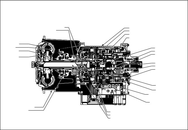
8 |
Transmission Family Product 3000 .1±1 Figure Section PTOÐCross with |
CONVERTER MODULE
•TURBINE
•PUMP
•LOCKUP CLUTCH/DAMPER
•STATOR
FRONT SUPPORT/OIL PUMP MODULE |
MAIN HOUSING MODULE |
• FRONT SUPPORT |
• MAIN HOUSING |
• OIL PUMP |
• C3 CLUTCH |
|
• C4 CLUTCH |
|
• C5 CLUTCH |
MAIN SHAFT MODULE
• MAIN SHAFT
• P2 SUN
• P3 SUN
REAR COVER MODULE |
• OUTPUT SHAFT |
• P3 |
• C5 PISTON |
|
|
P2 MODULE |
|
|
|
P1 MODULE |
|
|
|
OIL LEVEL SENSOR |
|
|
|
CONTROL MODULE |
|
CONVERTER HOUSING MODULE |
|
• ELECTRO-HYDRAULIC |
|
|
CONTROLS |
||
• CONVERTER HOUSING |
ROTATING CLUTCH MODULE |
||
|
|||
• PTO DRIVE GEAR |
|
||
• C1 CLUTCH |
|
||
|
|
||
|
• C2 CLUTCH |
|
|
|
• TURBINE SHAFT |
V03350.08.00 |
9 |
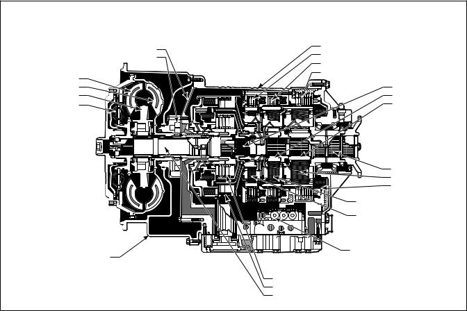
Family Product 3000 .1±2 Figure |
|
Section TransmissionÐCross |
FRONT SUPPORT/OIL PUMP MODULE |
MAIN HOUSING MODULE |
||
MAIN HOUSING |
|||
FRONT SUPPORT |
|||
C3 |
CLUTCH |
||
OIL PUMP |
|||
C4 |
CLUTCH |
||
CONVERTER MODULE |
|||
C5 |
CLUTCH |
||
TURBINE |
|
MAIN SHAFT MODULE |
|
PUMP |
|
MAIN SHAFT |
|
STATOR |
|
P2 SUN |
|
LOCKUP |
|
P3 SUN |
|
CLUTCH/DAMPER |
|
|
|
CONVERTER HOUSING MODULE CONVERTER HOUSING
REAR COVER MODULE |
OUTPUT SHAFT |
P3 MODULE |
C5 PISTON |
P2 MODULE
P1 MODULE
CONTROL MODULE
|
ELECTRO-HYDRAULIC CONTROLS |
|
ROTATING CLUTCH MODULE |
|
|
C1 |
CLUTCH |
|
C2 |
CLUTCH |
|
TURBINE SHAFT |
V07286.02.00 |
|
|
|
|
10 |
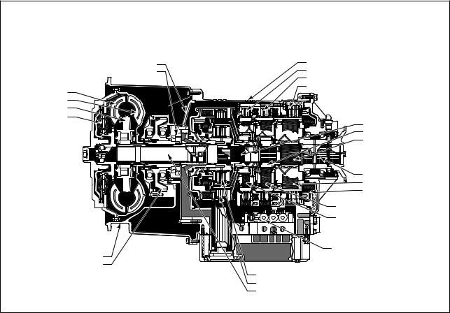
Transmission Family Product 4000 .1±3 Figure Section RetarderÐCross with |
FRONT SUPPORT/OIL PUMP MODULE |
MAIN HOUSING MODULE |
||
MAIN HOUSING |
|
||
FRONT SUPPORT |
|
||
C3 CLUTCH |
RETARDER MODULE |
||
OIL PUMP |
|||
C4 CLUTCH |
STATOR ASSEMBLY |
||
CONVERTER MODULE |
|||
C5 CLUTCH |
ROTOR |
||
TURBINE |
|
HOUSING ASSEMBLY |
|
PUMP |
|
|
|
STATOR |
|
|
|
LOCKUP |
|
|
|
CLUTCH/DAMPER |
|
MAIN SHAFT MODULE |
|
|
|
||
|
|
MAIN SHAFT |
|
|
|
P2 SUN |
|
|
|
P3 SUN |
|
|
|
P3 MODULE |
|
|
|
P2 MODULE |
|
|
|
P1 MODULE |
|
CONVERTER HOUSING MODULE |
|
|
CONTROL MODULE |
CONVERTER HOUSING |
ROTATING CLUTCH MODULE |
ELECTRO-HYDRAULIC CONTROLS |
|
|
|
||
|
C1 |
CLUTCH |
|
|
C2 |
CLUTCH |
|
|
TURBINE SHAFT |
V07287.06.00 |
|
11 |
Transmission Family Product 4000 .1±4 Figure Section PTOÐCross with |
FRONT SUPPORT/OIL PUMP MODULE |
MAIN HOUSING MODULE |
||
FRONT SUPPORT |
MAIN HOUSING |
||
OIL PUMP |
C3 |
CLUTCH |
|
CONVERTER MODULE |
C4 |
CLUTCH |
|
C5 |
CLUTCH |
||
TURBINE |
|||
|
|
||
PUMP |
|
|
|
STATOR |
|
MAIN SHAFT MODULE |
|
LOCKUP |
|
||
CLUTCH/DAMPER |
|
MAIN SHAFT |
|
|
|
P2 SUN |
|
|
|
P3 SUN |
|
REAR COVER MODULE |
OUTPUT SHAFT |
P3 MODULE |
C5 PISTON |
P2 MODULE
P1 MODULE
|
|
CONTROL MODULE |
CONVERTER HOUSING MODULE |
|
ELECTRO-HYDRAULIC CONTROLS |
CONVERTER HOUSING |
|
|
PTO DRIVE GEAR |
ROTATING CLUTCH MODULE |
|
|
||
|
C1 |
CLUTCH |
|
C2 |
CLUTCH |
|
TURBINE SHAFT |
|
|
|
V07288.03.00 |

|
|
|
CONVERTER MODULE |
FRONT SUPPORT/OIL PUMP MODULE |
MAIN HOUSING MODULE |
C6 ADAPTER HOUSING |
|
|
Figure |
•TURBINE |
•OIL PUMP |
•MAIN HOUSING |
MODULE |
|
|
•PUMP |
•FRONT SUPPORT |
•C3 CLUTCH |
•C6 ADAPTER HOUSING |
|
|
|
•STATOR |
|
•C4 CLUTCH |
•C6 CLUTC H |
|
|
|
|
|
|||
|
|
|
|
•P4 MODULE |
||
|
|
|
•LOCKUP |
|
•C5 CLUTCH |
|
|
|
|
|
|
||
|
|
1±5 |
CLUTCH/ |
|
|
REAR COVER |
|
|
DAMPER |
|
|
||
|
|
|
|
MODULE |
||
|
SectionSpeedÐCross-7 |
TransmissionFamily Product 4000 . |
|
|
|
•REAR COVE R |
|
|
|
|
•OUTPUT SHAF T |
||
12 |
•CONVERTER HOUSIN G |
|
|
MAIN SHAFT |
||
|
|
|
|
|
|
MODULE |
|
|
|
|
|
|
•MAIN SHAF T |
|
|
|
|
|
|
•P3 SUN |
|
|
|
|
|
|
•P2 SUN |
|
|
|
CONVERTER |
|
|
|
|
|
|
HOUSING MODULE |
|
|
P3 MODULE |
|
|
|
|
|
|
|
|
|
|
|
|
|
P2 MODULE |
|
|
|
ROTATING CLUTCH MODULE |
|
|
P1 MODULE |
|
|
|
|
|
|
|
|
|
|
•TURBINE SHAFT |
|
|
V05641.03.00 |
|
|
|
•C1 CLUTCH |
|
|
|
|
|
|
•C2 CLUTCH |
|
|
|
BREATHER |
|
|
ASSEMBLY PADS |
|
|
|
PTO |
|
|
PROVISION |
|
|
INPUT |
|
OUTPUT |
SPEED |
|
SENSOR |
||
SPEED |
||
|
||
SENSOR |
|
|
|
FEEDTHROUGH HARNESS |
|
|
CONNECTOR |
|
COOLER PORTS |
NAMEPLATE |
|
NOTE: Inch Series Threads |
MAIN-PRESSURE TAP |
|
|
||
|
NOTE: Inch Series Threads |
|
RIGHT-REAR VIEW |
||
BREATHER |
||
|
FEEDTHROUGH HARNESS |
|
|
CONNECTOR |
|
TORQUE CONVERTER |
|
|
WITH LOCKUP CLUTCH |
ASSEMBLY PADS |
|
AND TORSIONAL DAMPER |
(BOTH SIDES) |
|
|
MAIN-PRESSURE TAP |
|
|
NOTE: Inch Series Threads |
|
PTO PROVISION |
|
|
(AVAILABLE BOTH SIDES) |
|
|
LEFT-FRONT VIEW |
||
|
V07289.02.00 |
|
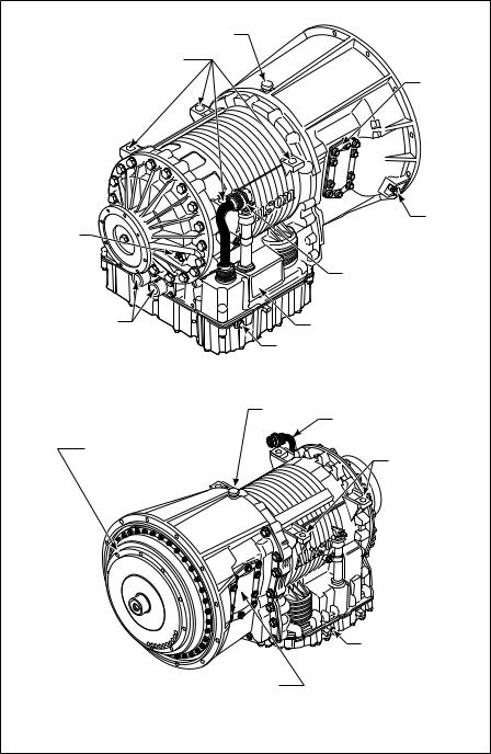
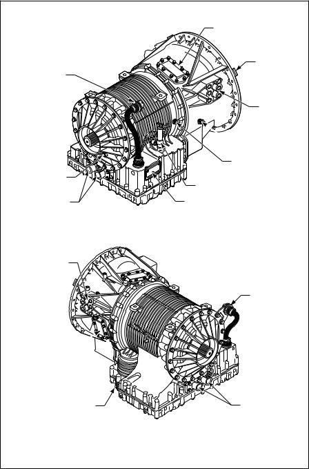
Figure 1±6. 3000 Product Family Transmission with PTO
13
BREATHER
ASSEMBLY PADS
FEEDTHROUGH
HARNESS
CONNECTOR
|
|
INPUT SPEED |
|
|
SENSOR |
|
|
NAMEPLATE |
COOLER PORTS |
|
|
NOTE: Inch Series Threads |
|
MAIN-PRESSURE TAP |
|
|
|
|
|
NOTE: Inch Series Threads |
|
RIGHT-REAR VIEW |
|
|
BREATHER |
ASSEMBLY PADS |
|
|
|
TORQUE CONVERTER |
|
(BOTH SIDES) |
|
OUTPUT |
|
WITH LOCKUP CLUTCH |
|
|
AND TORSIONAL DAMPER |
|
RETARDER |
|
TO RETARDER |
|
ACCUMULATOR |
|
OIL FILL TUBE AND |
|
DIPSTICK |
|
(AVAILABLE ON |
MAIN-PRESSURE TAP |
BOTH SIDES) |
NOTE: Inch series threads |
|
LEFT-FRONT VIEW |
V07290.01.00 |
Figure 1±7. 3000 Product Family Transmission with Retarder
14
BREATHER |
ASSEMBLY PADS |
||
|
|||
|
|
FEEDTHROUGH |
|
|
|
HARNESS |
|
|
|
CONNECTOR |
|
|
|
OUTPUT |
|
|
|
SPEED |
|
|
|
SENSOR |
|
|
|
RETARDER |
|
|
|
VALVE BODY |
|
|
|
CONNECTOR |
|
MAIN-PRESSURE TAP |
|
|
|
NOTE: Inch Series Threads |
|
|
|
TACHOGRAPH PROVISION |
|
|
|
NOTE: Metric Series Threads |
|
|
|
SPEEDOMETER PROVISION |
|
COOLER PORTS |
|
NOTE: Inch Series Threads |
|
NOTE: Inch Series Threads |
|
|
LEFT-REAR VIEW |
|
|
|
BREATHER |
ASSEMBLY PADS |
|
TORQUE CONVERTER |
|
(BOTH SIDES) |
|
|
|
||
WITH LOCKUP CLUTCH |
OUTPUT |
||
AND TORSIONAL DAMPER |
|||
RETARDER |
|||
|
|
||
|
|
TO RETARDER |
|
|
|
ACCUMULATOR |
|
|
|
OIL FILL TUBE |
|
|
|
AND DIPSTICK |
|
|
MAIN-PRESSURE TAP |
(AVAILABLE ON |
|
|
NOTE: Inch series threads |
BOTH SIDES) |
|
|
LEFT-FRONT VIEW |
V07300.01.00 |
|
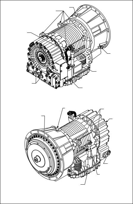
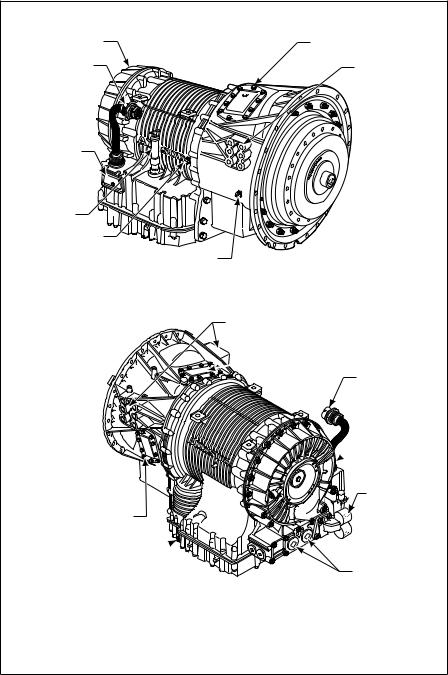
Figure 1±8. 3000 Product Family Transmission with Retarder and Provisions for Tachograph and Speedometer
15
BREATHER |
ASSEMBLY PADS |
|
FEEDTHROUGH
HARNESS
CONNECTOR
OUTPUT
SPEED
SENSOR
RETARDER
VALVE BODY
CONNECTOR
MAIN-PRESSURE TAP
NOTE: Inch Series Threads
TACHOGRAPH PROVISION |
COOLER PORTS |
|
NOTE: Inch Series Threads |
NOTE: Inch Series Threads |
|
LEFT-REAR VIEW |
|
|
BREATHER |
ASSEMBLY PADS |
|
TORQUE CONVERTER |
(BOTH SIDES) |
|
|
||
WITH LOCKUP CLUTCH |
OUTPUT |
|
AND TORSIONAL DAMPER |
||
RETARDER |
||
|
|
TO RETARDER |
|
ACCUMULATOR |
|
OIL FILL TUBE |
|
AND DIPSTICK |
MAIN-PRESSURE TAP |
(AVAILABLE ON |
NOTE: Inch series threads |
BOTH SIDES) |
LEFT-FRONT VIEW |
V07401.02.00 |
Figure 1±9. 3000 Product Family Transmission with Retarder and Provisions for Tachograph and Sump Cooler
16
PTO
(TOP RIGHT POSITION)
SHIPPING
BRACKET (3)
FEEDTHROUGH
HARNESS CONNECTOR
MOUNTING PAD
 ENGINE SPEED
SENSOR
TURBINE SPEED
SENSOR
OUTPUT SPEED |
|
SENSOR |
FILL TUBE |
COOLER PORTS |
NAMEPLATE |
RIGHT-REAR VIEW
MOUNTING PAD (BOTH SIDES)
FEEDTHROUGH
HARNESS
CONNECTOR
PTO (BOTTOM LEFT
POSITION)
MAIN-PRESSURE TAP |
COOLER PORTS |
LEFT-REAR VIEW
V07291.00.01
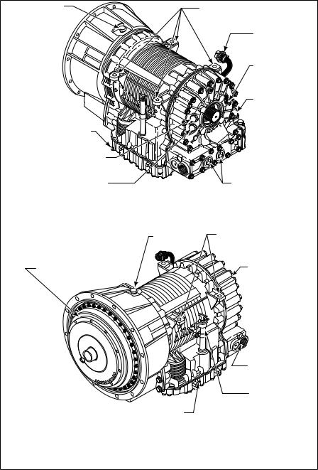
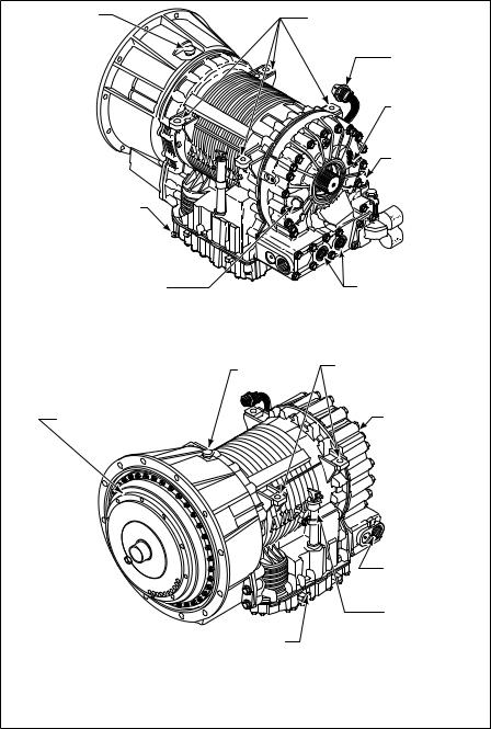
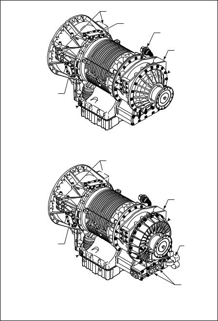
Figure 1±10. 4000 Product Family Transmission with PTO
17
RETARDER
FEEDTHROUGH
HARNESS
CONNECTOR
NAMEPLATE |
FILL TUBE  TURBINE
SPEED SENSOR
ENGINE SPEED SENSOR
PTO (TOP RIGHT POSITION)
MOUNTING PADS (BOTH SIDES)
RIGHT-FRONT VIEW
PTO (BOTTOM LEFT
POSITION)
MAIN-PRESSURE TAP
MOUNTING PADS (BOTH SIDES)
 PTO (TOP RIGHT POSITION)
FEEDTHROUGH HARNESS CONNECTOR
 RETARDER
SUMP
COOLER
PROVISION
COOLER PORTS |
LEFT-REAR VIEW
V07292.03.00
Figure 1±11. 4000 Product Family Transmission with Retarder and PTO
18
MOUNTING PADS (BOTH SIDES)
PTO (TOP RIGHT POSITION)
FEEDTHROUGH
HARNESS
CONNECTOR
C6 ADAPTER
HOUSING
 REAR COVER
PTO (BOTTOM LEFT
POSITION)
MAIN-PRESSURE TAP
LEFT-REAR
PTO (BOTTOM LEFT
POSITION)
MAIN-PRESSURE TAP
MOUNTING PADS (BOTH SIDES)
 PTO (TOP RIGHT POSITION)
C6 ADAPTER
HOUSING
 RETARDER
SUMP
COOLER
PROVISION
COOLER |
PORTS |
LEFT-REAR
V07399.00.02
Figure 1±12. 4000 Product Family 7-Speed Transmission with PTO (Top) and 7-Speed with PTO and Retarder (Bottom)
19
Section II |
PREVENTIVE |
|
MAINTENANCE |
|
|
|
|
|
|
|
|
2±1. PERIODIC INSPECTION AND CARE
Clean and inspect the exterior of the transmission at regular intervals. Severity of service and operating conditions determine the frequency of these inspections. Inspect the transmission for:
•Loose boltsÐtransmission and mounting components
•Fluid leaksÐrepair immediately
•Loose, dirty, or improperly adjusted throttle sensor
•Damaged or loose hoses
•Worn, frayed, or improperly routed electrical harnesses
•Worn or frayed electrical connections
•Dented, worn or out-of-phase driveline U-joints and slip ®ttings
•Clogged or dirty breather
Inspect the vehicle cooling system occasionally for evidence of transmission ¯uid. Transmission ¯uid in the vehicle cooling system indicates a faulty oil cooler.
CAUTION: When welding on the vehicle:
• DO NOT WELD on the vehicle without disconnecting all control system wiring harness connectors from the ECU.
•DO NOT WELD on the vehicle without disconnecting ECU battery power and ground leads.
•DO NOT WELD on any control components.
•DO NOT CONNECT welding cables to any control components.
A label (ST2067EN) describing on-vehicle welding precautions is available from your authorized Allison service dealer and should be installed in a conspicuous place. A vehicle used in a vocation that requires frequent modi®cations or repairs involving welding must have an on-vehicle welding label.
2±2. IMPORTANCE OF PROPER TRANSMISSION FLUID LEVEL
Transmission ¯uid cools, lubricates, and transmits hydraulic power. Always maintain proper ¯uid level. If ¯uid level is too low, the torque converter and clutches do not receive an adequate supply of ¯uid and the transmission overheats.
20
If the level is too high, the ¯uid aeratesÐcausing the transmission to shift erratically and overheat. Fluid may be expelled through the breather or dipstick tube when the ¯uid level is too high.
2±3. TRANSMISSION FLUID TEST
a. Electronic Fluid Test Procedure. Fluid level can be electronically displayed on a pushbutton (non-strip type) shift selector, lever shift selector, or Allison DOC™ For PC±Service Tool if there is an oil level sensor (OLS) installed and ªautodetectedº by the WTEC III control system. Frequently test for the presence of oil level diagnostics if the transmission is known to contain an OLS.
If an OLS is not detected during the ®rst 49 engine starts, the WTEC III system concludes that no OLS is present. If an OLS is known to be present, but has not been ªautodetectedº, then troubleshoot the OLS circuit.
After the OLS circuit is repaired, reset ªautodetectº or manually select the OLS function using the Allison DOC™ service tool and then reset autodetect (refer to TS2973EN, WTEC III Troubleshooting Manual for detailed troubleshooting procedures).
•Displaying Fluid Level Information. Use the following procedure to display ¯uid level information (refer to Figure 2±1).
ÐFor a pushbutton shift selector: Simultaneously press the ↑ (Up) and ↓ (Down) arrow buttons once.
ÐFor a lever shift selector: Press the DISPLAY MODE/DIAGNOSTIC button once.
ÐFor Allison DOC™ For PC±service tool: Connect the Allison DOC™ For PC±service tool to the diagnostic tool connector on the wiring harness and scroll down the DIAGNOSTIC DATA LIST to read the OLS information.
•Fluid Level Display Criteria. As soon as ¯uid level information is requested, the ECU determines if conditions are right to allow display. Certain operating conditions must have been met for a period of two minutes before ¯uid level is displayed. These operating conditions are:
ÐEngine at idle
ÐSump ¯uid at operating temperature 60±104°C (140±220°F)
ÐTransmission output shaft stopped
ÐTransmission in neutral
ÐOLS functioning properly
21


 HOLD OVERRIDE BUTTON

MODE INDICATOR (LED)
1 |
|
R |
|
MODE |
MODE |
2 |
|
N |
3 |
MODE BUTTON |
D |
4 |
|
|
|
5 |
|
5 |
MODE ID |
4 |
D |
3 |
|
N |
DIGITAL DISPLAY |
2 |
R |
1 |
DISPLAY MODE/
DIAGNOSTIC BUTTON
SIX-SPEED, LEFT-HAND |
|
SIX-SPEED, RIGHT-HAND |
||||
LEVER SELECTOR |
|
LEVER SELECTOR |
||||
|
DIGITAL DISPLAY |
|
|
|
|
|
|
MODE ID |
1 |
D |
|
|
|
|
|
D |
N |
R |
||
|
MODE |
2 |
||||
|
INDICATOR (LED) |
N |
|
|
|
|
R |
3 |
|
|
|
||
MODE |
|
|
|
|||
|
Push simultaneously |
|
R |
|
|
|
N |
to enter diagnostic |
D |
1 2 |
3 |
D N R |
|
|
mode and fluid level |
N |
|
|
|
|
D |
check (optional) |
|
|
|
|
|
|
PUSHBUTTON |
R |
STRIP PUSHBUTTON |
|||
|
SELECTOR |
|
SHIFT SELECTORS |
|||
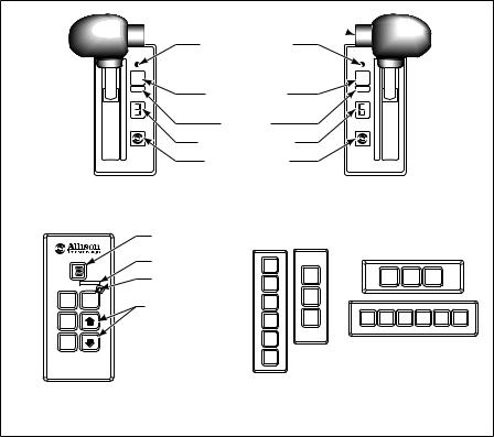
NOTE: Number displayed is highest forward range available in selected position.
Visually check to confirm range selected. If display is flashing – shift is inhibited.
V03496.02
Figure 2±1. Typical Shift Selectors
Information is displayed immediately if the two minute time period elapsed before a ¯uid level data request was made. However, if the two minute period has not elapsed, there will be a countdown display before ¯uid level information displays. The countdown display ¯ashes constantly. Countdown starts at 8 and decreases sequentially to 1 during the two minute period. When ¯uid level data is requested, and the two minute countdown is in process, the ¯ashing display shows the number corresponding to the countdown progress.
For example:
•If the ¯uid level data was requested in the middle of the two minute countdown period, the display would ¯ash a 5 or a 4 and decrease to 1.
•Shift Selector Display. Fluid level information is displayed one character at a time as in Table 2±1:
22

Table 2±1. Fluid Level Shift Selector Display
Display Sequence |
Interpretation of Display |
|||
o L |
o K |
|
Fluid level is correct |
|
o L |
L o |
1 |
Fluid level is 1 |
quart low |
o L |
H I |
1 |
Fluid level is 1 |
quart high |
The shift selector display will also show ªinvalid for displayº codes one character at a time. An ªinvalid for displayº code is returned when ¯uid level data is requested, but an operational condition has not been met. The ªinvalid for displayº condition interrupts the two minute countdown (momentary increase in engine speed does not affect the countdown). The ªinvalid for displayº codes and their meaning are:
|
Table 2±2. Invalid For Display Codes |
||
Display Sequence |
Interpretation of Display |
||
o L |
± 5 |
0 |
Engine rpm too low |
o L |
± 5 |
9 |
Engine rpm too high |
o L |
± 6 |
5 |
N (Neutral) not selected |
o L |
± 7 |
0 |
Sump ¯uid temperature too low |
o L |
± 7 |
9 |
Sump ¯uid temperature too high |
o L |
± 8 |
9 |
Output shaft rotation |
o L |
± 9 |
5 |
Sensor failure |
NOTE: Report sensor failure to a distributor or dealer in your area. Consult the telephone directory for the Allison Transmission distributor or dealer near you.
The countdown is restarted when the condition causing the ªinvalid for displayº code 59 has been corrected. The countdown is not restarted if there is a momentary increase in engine rpm which may generate a code 59. ªInvalid for displayº messages are as follows:
•Allison DOC™ Display. ªInvalid for displayº messages are displayed in the Oil (±) ®eld of the Data Monitor.
|
|
Allison DOC™ Message |
OL |
Ð |
SETTLING TIME X |
OL |
Ð |
ENGINE SPEED LO |
OL |
Ð |
ENGINE SPEED HI |
OL |
Ð |
SELECT N (NEUTRAL) |
OL |
Ð |
SUMP TEMP LO |
23

|
|
Allison DOC™ Message |
OL |
Ð |
SUMP TEMP HI |
OL |
Ð |
OUTPUT SPEED HI |
OL |
Ð |
CHECK CODES |
•Exiting the Fluid Level Mode. Exit as follows:
ÐFor a pushbutton shift selector, press the N (Neutral) pushbutton once.
ÐFor a lever selector, press the DISPLAY MODE/DIAGNOSTIC button once or move the lever to a range position.
ÐAllison DOC™ does not use a special Fluid Level Mode. b. Manual Fluid Test Procedure.
WARNING: To help avoid personal injury or property damage caused by sudden and unexpected vehicle movement, do not determine the ¯uid level until you:
1.Put the transmission into N (Neutral).
2.Apply the parking brake and emergency brakes and make sure they are properly engaged.
3.Chock the wheels and take any other steps necessary to keep the vehicle from moving.
Clean all dirt from around the end of the ¯uid ®ll tube before removing the dipstick. Do not allow dirt or foreign matter to enter the transmission. Dirt or foreign matter in the hydraulic system may cause undue wear of transmission parts, make valves stick, and clog passages. Determine the ¯uid level using the following procedure and report any abnormal ¯uid levels to your service management.
c. Cold Test Procedure. The purpose of the cold test is to determine if the transmission has enough ¯uid to be safely operated until a hot test can be made.
CAUTION: The ¯uid level rises as ¯uid temperature increases. DO NOT ®ll above the ªCOLD CHECKº band if the transmission ¯uid is below normal operating temperature. During operation, an over full transmission can become overheated, leading to transmission damage.
1.Park the vehicle on a level surface. Apply the parking brake and chock the wheels.
2.Run the engine for at least one minute. Shift to D (Drive), then to N (Neutral), and then to R (Reverse) to ®ll the hydraulic system.
3.Shift to N (Neutral) and allow the engine to idle (500±800 rpm).
24
 Loading...