


HT 700
Mechanic’s
Tips
Allison Transmission
Division of General Motors Corporation
P.O. B ox 894 Indianapolis, Indiana 46206-0894
Printed in U.S.A. Copyright © 1995 General Motors Corp.
i
IT IS YOUR RESPONSIBILITY to be completely familiar with the warnings and
cautions described in this handbook. It is, however, important to understand that these
warnings and cautions are not exhaustive. Allison Transmission could not possibly
know, evaluate, and advise the service trade of all conceivable ways in which service
might be done or of the possible hazardous consequences of each way. Consequently,
Allison Transmission has not undertaken any such broad evaluation. Accordingly,
ANYONE WHO USES A SERVICE PROCEDURE OR TOOL WHICH IS NOT
RECOMMENDED BY ALLISON TRANSMISSION MUST rst be thoroughly
satised that neither personal safety nor equipment safety will be jeopardized by the
service methods selected.
Proper service and repair is important to the safe, reliable operation of the equipment.
The service procedures recommended by Allison Transmission and described in this
handbook are effective methods for performing service operations. Some of these
service operations require the use of tools specially designed for the purpose. The
special tools should be used when and as recommended.
Three types of headings are used in this manual to attract your attention. These
warnings and cautions advise of specic methods or actions that can result in personal
injury, damage to the equipment, or cause the equipment to become unsafe.
WARNING: A warning is used when an operating procedure, practice,
etc., if not correctly followed, could result in personal injury or loss of life.
CAUTION: A caution is used when an operating procedure,
practice, etc., if not strictly observed, could result in damage to or
destruction of equipment.
NOTE:
A note is used when an operating procedure, practice, etc., is
essential to highlight.
ii
Paragraph Description Page
1–1. Periodic Inspection and Care . . . . . . . . . . . . . . . . . . . . . . . . . . . 1
1–2. Importance of Proper Transmission Fluid Level . . . . . . . . . . . . 1
1–3. Transmission Fluid Check Procedures. . . . . . . . . . . . . . . . . . . . 2
1–4. Keeping Transmission Fluid Clean . . . . . . . . . . . . . . . . . . . . . . 5
1–5. Automatic Transmission Fluid Recommendations . . . . . . . . . . 5
1–6. Transmission Fluid and Filter Change Intervals . . . . . . . . . . . . 6
1–7. Fluid Temperatures . . . . . . . . . . . . . . . . . . . . . . . . . . . . . . . . . . 7
1–8. High-Efficiency, Main-Pressure External Filter Change. . . . . . 8
1–9. Transmission Fluid Contamination . . . . . . . . . . . . . . . . . . . . . . 8
1–10. Transmission Fluid and Filter Change Procedure . . . . . . . . . . . 9
1–11. Auxiliary Filter. . . . . . . . . . . . . . . . . . . . . . . . . . . . . . . . . . . . . . 9
1–12. Breather . . . . . . . . . . . . . . . . . . . . . . . . . . . . . . . . . . . . . . . . . . . 10
1–13. Transmission Stall Test and Neutral Cool-Down Check . . . . . . 10
2–1. Draining Transmission. . . . . . . . . . . . . . . . . . . . . . . . . . . . . . . . 13
2–2. Disconnecting Controls . . . . . . . . . . . . . . . . . . . . . . . . . . . . . . . 13
2–3. Uncoupling From Driveline, Engine, and Vehicle. . . . . . . . . . . 14
2–4. Removing the Transmission. . . . . . . . . . . . . . . . . . . . . . . . . . . . 14
2–5. Removing Input and Output Flanges or Yokes . . . . . . . . . . . . . 14
2–6. Rebuild, Overhaul Instructions . . . . . . . . . . . . . . . . . . . . . . . . . 15
3–1. Checking Input Components . . . . . . . . . . . . . . . . . . . . . . . . . . . 16
3–2. Installing Output Flange and Input Flange
(Remote-Mounted Transmission) . . . . . . . . . . . . . . . . . . . . . . . 16
3–3. Installing PTO . . . . . . . . . . . . . . . . . . . . . . . . . . . . . . . . . . . . . . 17
3–4. Installing Transmission Fill Tube and Seal . . . . . . . . . . . . . . . . 18
3–5. Checking Plugs, Openings . . . . . . . . . . . . . . . . . . . . . . . . . . . . . 18
iii
Paragraph Description Page
4–1. Engine, Transmission Adaptation Requirements. . . . . . . . . . . . 19
4–2. Checking Flexplate Drive Assembly . . . . . . . . . . . . . . . . . . . . . 20
4–3. Checking Input Drive Components
(Remote-Mounted Transmissions). . . . . . . . . . . . . . . . . . . . . . . 20
4–4. Chassis and Driveline Inspection . . . . . . . . . . . . . . . . . . . . . . . . 22
4–5. Cooler, Filter, and Lines . . . . . . . . . . . . . . . . . . . . . . . . . . . . . . 22
4–6. Checking Controls . . . . . . . . . . . . . . . . . . . . . . . . . . . . . . . . . . . 23
5–1. Handling. . . . . . . . . . . . . . . . . . . . . . . . . . . . . . . . . . . . . . . . . . . 27
5–2. Mounting to Engine . . . . . . . . . . . . . . . . . . . . . . . . . . . . . . . . . . 27
5–3. Installing Transmission Mounting Components . . . . . . . . . . . . 28
5–4. Coupling to Driveline. . . . . . . . . . . . . . . . . . . . . . . . . . . . . . . . . 28
5–5. Coupling to Engine (Remote-Mounted Transmission) . . . . . . . 28
5–6. Connecting Input Retarder Control . . . . . . . . . . . . . . . . . . . . . . 29
5–7. Connecting Output Retarder Control . . . . . . . . . . . . . . . . . . . . . 29
5–8. Connecting Power Takeoff Controls . . . . . . . . . . . . . . . . . . . . . 29
5–9. Connecting Parking Brake Control . . . . . . . . . . . . . . . . . . . . . . 30
5–10. Connecting Cooler, Filter. . . . . . . . . . . . . . . . . . . . . . . . . . . . . . 30
5–11. Installing Auxiliary Filter. . . . . . . . . . . . . . . . . . . . . . . . . . . . . . 30
5–12. Connecting Speedometer Drive . . . . . . . . . . . . . . . . . . . . . . . . . 30
5–13. Installing Temperature and Pressure Sensors,
Connecting Electrical Components . . . . . . . . . . . . . . . . . . . . . . 32
5–14. Filling the Hydraulic System . . . . . . . . . . . . . . . . . . . . . . . . . . . 32
6–1. Installation Checklist . . . . . . . . . . . . . . . . . . . . . . . . . . . . . . . . . 33
6–2. Road Test and Vehicle Operation Checklist . . . . . . . . . . . . . . . 35
7–1. Owner Assistance. . . . . . . . . . . . . . . . . . . . . . . . . . . . . . . . . . . . 37
7–2. Service Literature. . . . . . . . . . . . . . . . . . . . . . . . . . . . . . . . . . . . 39
iv

This handbook is a mechanic’s reference for removing, installing, and maintaining
the HT, HTB, CL(B)T 700 Commercial Electronic Control Series Automatic
Transmissions. All features of the transmission and vehicle involved in installation
procedures are discussed. The information presented will help the mechanic to
remove, install, and maintain the transmission in a manner that assures satisfactory
operation and long service life. For additional detailed information, refer to HT, HTB
700 Electronic Control Series Service Manual SM2004EN or CL(B)T 700 Series
Service Manual SM1314EN and CL(B)T 755 Electronic Control Series Service
Manual Supplement SM1992EN. Troubleshooting the electronic control system is
presented in Troubleshooting Manual TS2712EN.
DEXRON® is a registered trademark of General Motor Corporation.
Loctite® is a registered trademark of the Loctite Corporation.
Teon® is a registered trademark of the DuPont Corporation.
Pro-Link® is a registered trademark of Micro Processor Systems, Inc.
v
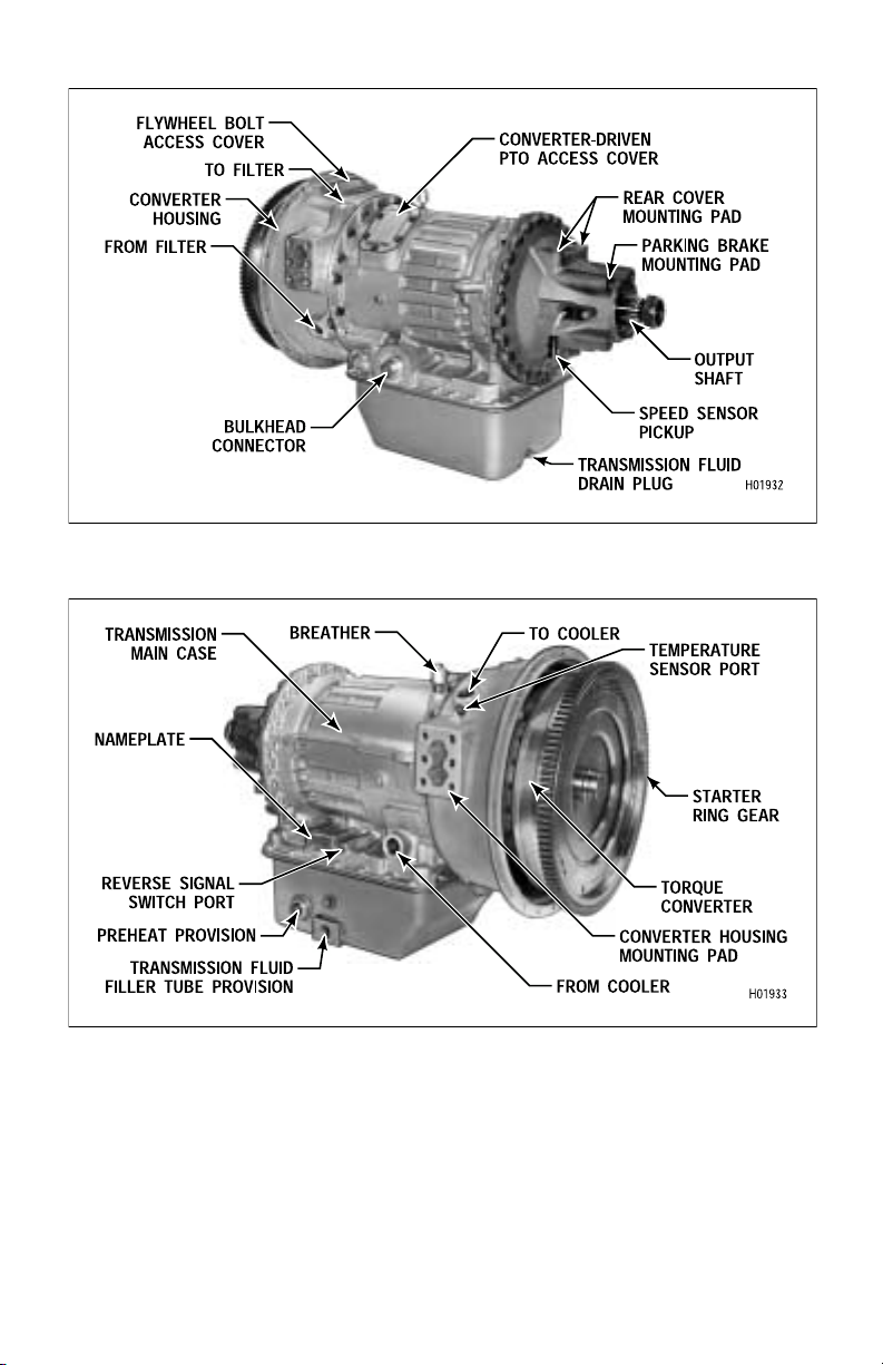
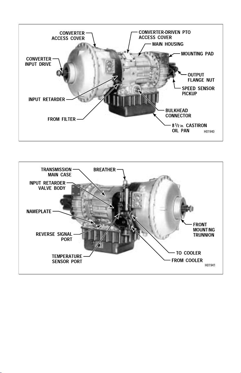
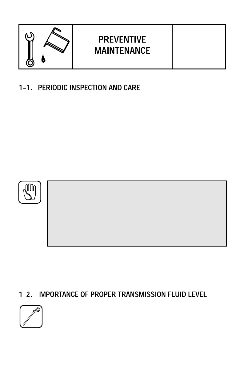
Model HT 741, 748 Transmission — Left-Rear View
Model HT 741, 748 Transmission — Right-Front View
vi
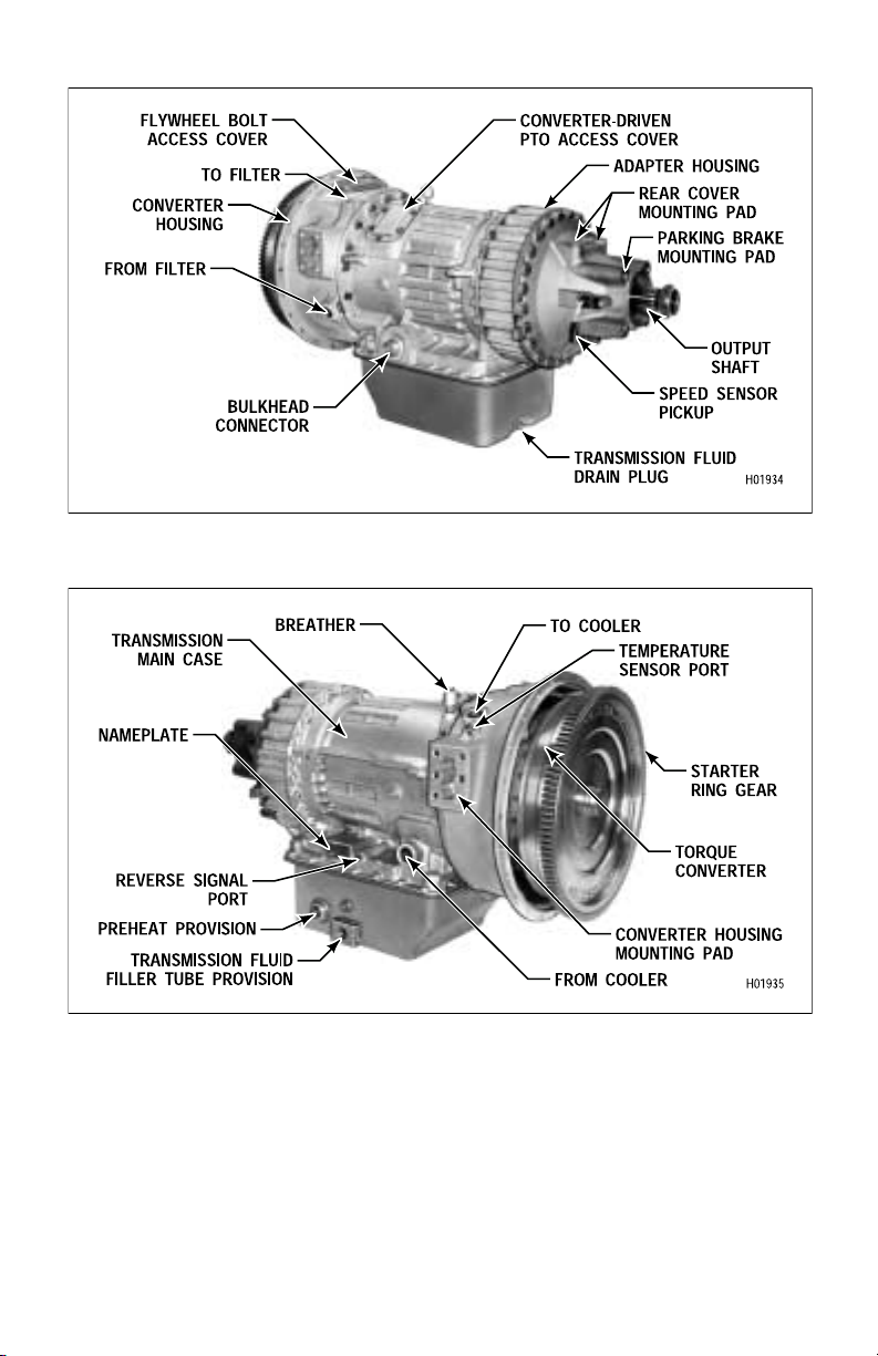
Model HT 755CR Transmission — Left-Rear View
Model HT 755CR Transmission — Right-Front View
vii
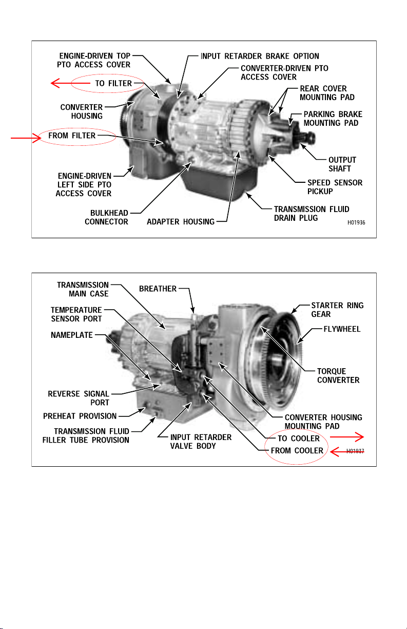
Model HT 755DR Transmission — Left-Rear View (With Input Retarder)
Model HT 755DR Transmission — Right-Front View (With Input Retarder)
viii
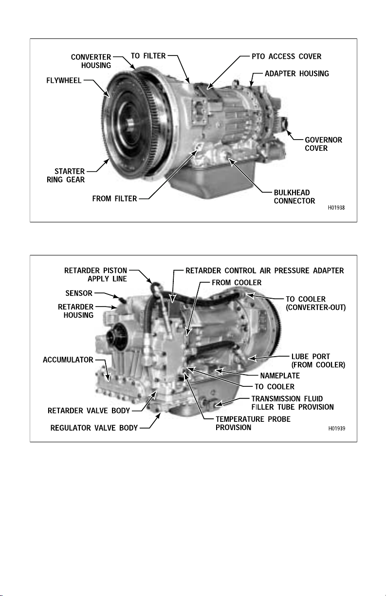
Model HTB 748 Transmission — Left-Front View (With Output Retarder)
Model HTB 748 Transmission — Right-Rear View (With Output Retarder)
ix
Model CLBT 755 Transmission — Left-Front View
Model CLBT 755 Transmission — Right-Front View
x
SECTION
I
Clean and inspect the exterior of the transmission at regular intervals. Severity of
service and operating conditions determine the frequency of these inspections.
Inspect the transmission for:
• loose bolts — transmission and mounting components
• uid leaks — repair immediately
• loose, dirty, or improperly adjusted throttle sensor linkage
• damaged or loose hoses
• worn, frayed, or improperly routed electrical harnesses
• worn or out-of-phase driveline U-joints and slip ttings
CAUTION: When welding on the vehicle:
• DO NOT WELD on the vehicle without disconnecting from
the ECU all control system wiring harness connectors.
• DO NOT WELD on the vehicle without disconnecting ECU
battery power and ground leads.
• DO NOT WELD on any control components.
• DO NOT CONNECT welding cables to any control components.
A label describing on-vehicle welding precautions is available from your authorized
Allison service dealer and should be installed in a conspicuous place. A vehicle used
in a vocation that requires frequent modications or repairs involving welding must
have an on-vehicle welding label.
Because the transmission uid cools, lubricates, and transmits hydraulic
power, it is important that the proper uid level be maintained at all times.
If the uid level is too low, the torque converter and clutches will not
receive an adequate supply of transmission uid, and the transmission
will overheat. If the uid level is too high, the uid aerates — causing the transmission
to shift erratically and overheat. Fluid may be expelled through the breather or
dipstick tube when the uid level is too high.
1
A severely low uid level causes the Allison Transmission Electronic Control to do
two things automatically —
• Turn on the CHECK TRANS light
• Prevent upshifting into the highest range
When the uid level is corrected, the transmission will return to normal operation.
Do not use the Electronic Control to replace regular uid level checks. Check the
level at the intervals specied in your vehicle service instructions.
WARNING: Take the following precautions so that unexpected,
possible sudden vehicle movement is avoided. Whenever it becomes
necessary to leave the vehicle, even momentarily, while the engine is
running, place the transmission shift selector in Neutral, set the parking brake and/or emergency brakes and chock the wheels.
a. Fluid Check Procedure.
Clean all dirt from around the end of the ll tube before removing the
dipstick. Do not allow the dirt or any foreign matter to enter the
transmission. Dirt or foreign matter may cause undue wear of the
transmission parts, make valves stick, and clog passages. Check the
uid level, manually, using the following procedure and record the level in your
maintenance log. To perform the uid level check, the engine must be running at
idle speed and the transmission must be in N (Neutral).
Add transmission uid to the transmission through the ll tube opening. Be sure to
use proper transmission uid and uid containers as discussed in Sections 1–4 and
1–5. Refer to Table 1–1 for approximate transmission uid capacity.
Table 1–1. Transmission Fluid Capacity
Application U.S. Quarts Liters
41⁄2 inch (114 mm) oil pan 34 32
6 inch (152 mm) oil pan 30 28.5
7 inch (178 mm) oil pan 30 28.5
81⁄2 inch (215 mm) oil pan 43 41
NOTE: Does not include external circuits.
2
b. Cold Check.
NOTE:
The purpose of the Cold Check is to determine if the transmission
has enough fluid to be safely operated until a hot check can be
made.
• Park the vehicle on a level surface. Apply the parking brake, and chock the
wheels.
CAUTION: The uid level rises as uid temperature increases.
DO NOT ll above the “COLD RUN” band if the transmission uid is
below normal operating temperatures.
• Run the engine for at least one minute. Shift to D (Drive) and then to
R (Reverse) to clear the hydraulic circuits of air. Then shift to N (Neutral) and
allow the engine to idle (500–800 rpm).
• Insert the dipstick into the tube and remove. Check the uid level reading.
Repeat the check procedure to verify the reading.
• If the uid level is within the “COLD RUN” band, the transmission may be
operated until the uid is hot enough to perform a “HOT RUN” check. If the
uid level is not within the “COLD RUN” band, add or drain as necessary to
bring it to the middle of the “COLD RUN” band.
• Perform a hot check as soon as the normal operating temperature of
160–200°F (71–93°C) is reached.
c. Hot Check.
CAUTION: The transmission uid must be hot to ensure an accurate
check. The uid level rises as temperature increases.
• Operate the transmission in D (Drive) until normal operating temperature is
reached:
160–200°F (71–93°C) sump temperature
180–220°F (82–104°C) converter-out temperature
• Park the vehicle on a level surface and shift to N (Neutral). Apply the parking
brake, and chock the wheels. Allow the engine to idle.
• With the engine running, remove the dipstick from the tube and wipe it clean.
• Insert the dipstick into the tube and remove. Check uid level reading. Repeat
the check procedure to verify the reading.
3
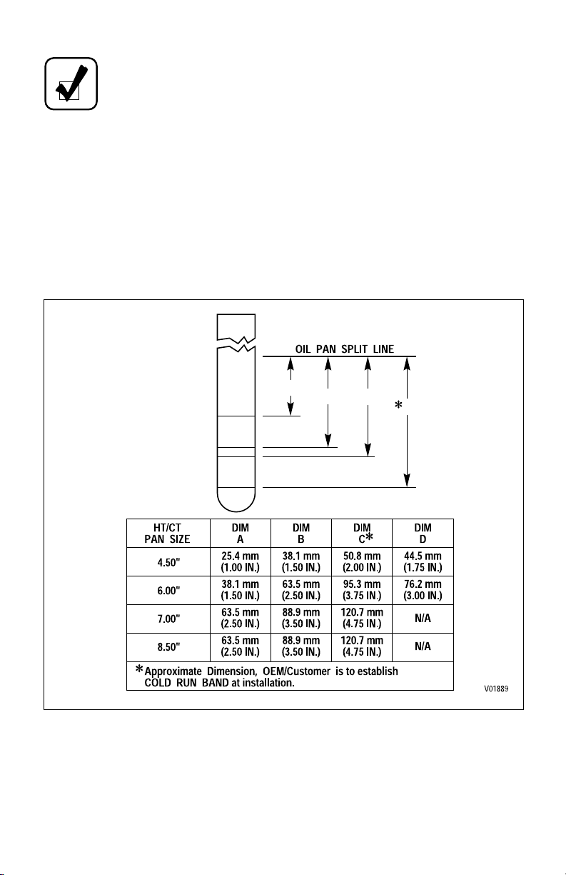
NOTE:
Safe operating level is within the “HOT RUN” band on the
dipstick, Figure 1–1.
• If the uid level is not within the “HOT RUN” band, add or drain as necessary
to bring the uid level to within the “HOT RUN” band.
d. Consistency of Readings.
• Always check the uid level at least twice and with the engine running.
Consistency is important to maintain accuracy of the reading. If inconsistent
reading persists, check the transmission breather to be sure it is clean and
unclogged.
A
B
D
C
HOT
RUN
RUN
COLD
Figure 1–1. Typical Dipstick Markings
4
CAUTION: Containers or llers that have been used for any antifreeze or engine coolant solution must not be used for the transmission uid. Antifreeze and coolant solutions contain ethylene glycol
which, if introduced into the transmission, can cause the clutch plates
to fail.
Transmission uid must be handled in clean containers, llers, etc., to prevent
foreign material from entering the transmission. Clean around the ller tube before
removing the dipstick. Lay the dipstick in a clean place while lling the
transmission.
• Hydraulic uids (oils) used in the transmission are important inuences on
transmission performance, reliability and durability. DEXRON®-III uid is
recommended for light-duty applications. Type C-4 uids are recommended
for severe-duty applications.
• Some DEXRON®-III uids are also qualied as Type C-4 uids. To ensure the
uid is qualied for use in Allison transmissions, check for a DEXRON®-III or
C-4 uid license, or approval numbers on the container, or consult the lubricant
manufacturer. Consult your Allison Transmission dealer or distributor before
using other uid types; uid types such as Type F, and universal farm uids may
or may not be properly qualied for use in your Allison transmission.
CAUTION: Disregarding minimum uid temperature limits can
result in transmission malfunction or reduced transmission life.
• When choosing the optimum viscosity grade of uid to use, duty cycle,
preheat capabilities, and/or geographical location must be taken into
consideration. Table 1–2 lists the minimum uid temperatures at which the
transmission may be safely operated. Preheat with auxiliary heating
equipment or by running the vehicle with the transmission in N (Neutral) for a
minimum of 20 minutes before attempting range operation.
5
 Loading...