

Page 1
Mechanic’s Tips
3000 and 4000
Product Families
MT3004EN
Page 2

Mechanic’s
2006 MARCH
Tips
MT3004EN
Allison Transmission
Allison WTEC III Controls
(Except 3000 P
3000 Product Family
4000 Product Family
roduct Family 7-Speed)
Alli son Tra nsmis sion, Inc.
P.O. Box 894 Indi anapo lis, India na 46206- 0894
www.al lison transmission.com
Printed in USA
Copyright © 2007 Allison Transmission, Inc.
Page 3

NOTES
2
Page 4

TABLE OF CONTENTS
SECTION I INTRODUCTION
1–1 ABOUT THIS MANUAL ............................... 7
SECTION II PREVENTIVE MAINTENANCE
2–1 PERIODIC INSPECTION AND CARE ...................... 20
2–2 IMPORTANCE OF PROPER TRANSMISSION FLUID LEVEL .......20
2–3 TRANSMISSION FLUID TEST ...........................21
2–4 KEEPING FLUID CLEAN ..............................27
2–5FLUIDRECOMMENDATIONS...........................27
2–6 TRANSMISSION FLUID AND FILTER CHANGE INTERVALS ...... 28
2–7 TRANSMISSION FLUID CONTAMINATION ..................32
2–8 TRANSMISSION FLUID AND FILTER CHANGE PROCEDURE ..... 35
2–9 FLUID LEAK DIAGNOSIS ............................. 37
2–10 BREATHER ...................................... 40
2–11 TROUBLESHOOTING ............................... 40
2–12 TRANSMISSION STALL TEST AND NEUTRAL COOL-DOWN
CHECK ......................................... 45
SECTION III REMOVING TRANSMISSION
3–1 DRAINING TRANSMISSION ............................51
3–2 DISCONNECTING CONTROLS .......................... 51
3–3 UNCOUPLING FROM DRIVELINE, ENGINE, AND VEHICLE ...... 52
3–4 REMOVING THE TRANSMISSION ........................53
3–5 REMOVING OUTPUT FLANGE OR YOKE ...................53
SECTION IV TRANSMISSION PREPARATION
4–1 INSPECTING INPUT COMPONENTS ...................... 55
4–2 INSTALLING OUTPUT FLANGE OR YOKE ..................55
4–3 INSTALLING PTO ...................................56
4–4 INSTALLING FILL TUBE AND SEAL ...................... 57
4–5 INSPECTING PLUGS AND OPENINGS ..................... 58
3
Page 5

SECTION V PREPARING VEHICLE FOR TRANSMISSION
INSTALLATION
5–1 ENGINE, TRANSMISSION ADAPTATION REQUIREMENTS ....... 59
5–2 CHECKING FLEXPLATE DRIVE ASSEMBLY .................62
5–3 CHASSIS AND DRIVELINE INSPECTION ................... 63
5–4 COOLER, FILTER, AND LINES .......................... 64
5–5 INSPECTING CONTROLS ............................. 65
SECTION VI INSTALLING TRANSMISSION INTO VEHICLE
6–1 HANDLING .......................................69
6–2 MOUNTING TO ENGINE .............................. 69
6–3 INSTALLING TRANSMISSION MOUNTING COMPONENTS ....... 70
6–4 COUPLING TO DRIVELINE ............................ 70
6–5 CONNECTING OUTPUT RETARDER ACCUMULATOR .......... 70
6–6 CONNECTING POWER TAKEOFF CONTROLS ................71
6–7 CONNECTING PARKING BRAKE CONTROL .................72
6–8 CONNECTING COOLER .............................. 72
6–9 CONNECTING ELECTRICAL COMPONENTS .................72
6–10 CONNECTING SPEEDOMETER DRIVE ....................74
6–11 FILLING HYDRAULIC SYSTEM ........................ 75
6–12 INSTALLATION INSPECTION LIST ...................... 75
SECTION VII INSPECTIONS AND ADJUSTMENTS
7–1 INSTALLATION INSPECTION LIST ....................... 76
7–2 ROAD TEST AND VEHICLE OPERATION INSPECTION LIST ...... 78
SECTION VIII CUSTOMER SERVICE
8–1 OWNER ASSISTANCE ................................ 80
8–2 SERVICE LITERATURE ............................... 80
4
Page 6

TRADEMARK USAGE
The following trademarks are the property of the companies indicated:
• Allison DOC™ is a trademark of General Motors Corporation.
• DEXRON®is a registered trademark of the General Motors Corporation.
• TranSynd™ is a trademark of Castrol Ltd.
• LPS Electro Contact Cleaner®is a registered trademark of LPS
Laboratories.
5
Page 7
WARNINGS, CAUTIONS, NOTES
IT IS YOUR RESPONSIBILITY to be completely familiar with the warnings
and cautions described in this handbook. It is, however, important to understand
that these warnings and cautions are not exhaustive. Allison Transmission could
not possibly know, evaluate, and advise the service trade of all conceivable ways
in which service might be done or of the possible hazardous consequences of each
way. The vehicle manufacturer is responsible for providing information related to
the operation of vehicle systems (including appropriate warnings, cautions, and
notes). Consequently, Allison Transmission has not undertaken any such broad
evaluation. Accordingly, ANYONE WHO USES A SERVICE PROCEDURE OR
TOOL WHICH IS NOT RECOMMENDED BY ALLISON TRANSMISSION OR
THE VEHICLE MANUFACTURER MUST first be thoroughly satisfied that
neither personal safety nor equipment safety will be jeopardized by the service
methods selected.
Proper service and repair is important to the safe, reliable operation of the
equipment. The service procedures recommended by Allison Transmission (or the
vehicle manufacturer) and described in this handbook are effective methods for
performing service operations. Some of these service operations require the use of
tools specially designed for the purpose. The special tools should be used when
and as recommended.
The following three types of headings are used in this manual to attract your
attention.
WARNING: A warning is used when an operating procedure, practice,
etc., if not correctly followed, could result in personal injury or loss of
life.
CAUTION: A caution is used when an operating procedure, practice,
etc., if not strictly observed, could result in damage to or destruction of
equipment.
NOTE: A note is used when an operating procedure, practice, etc., is
essential to highlight.
6
Page 8

INTRODUCTION Section I
1–1. ABOUT THIS MANUAL
This handbook is a mechanic’s reference for maintaining, removing, or installing
the 3000 and 4000 Product Families on-highway transmission with a WTEC III
control system. WTEC III controls were optional on the 3000 and 4000 Product
Families on-highway transmission units built in 1997, but became standard on
units built starting in 1998.
All features of the transmission and the vehicle involved in installation procedures
are discussed. The information presented will help the mechanic maintain, remove,
or install the transmission in a manner that promotes satisfactory operation and
long service life. For additional detailed information, refer to the appropriate
transmission service manual and electronic controls troubleshooting manual.
Unless specifically indicated otherwise, this handbook refers to all 3000 and 4000
Product Families on-highway transmissions, except 7-speed models. The
differences between the various transmissions are explained as required.
7
Page 9
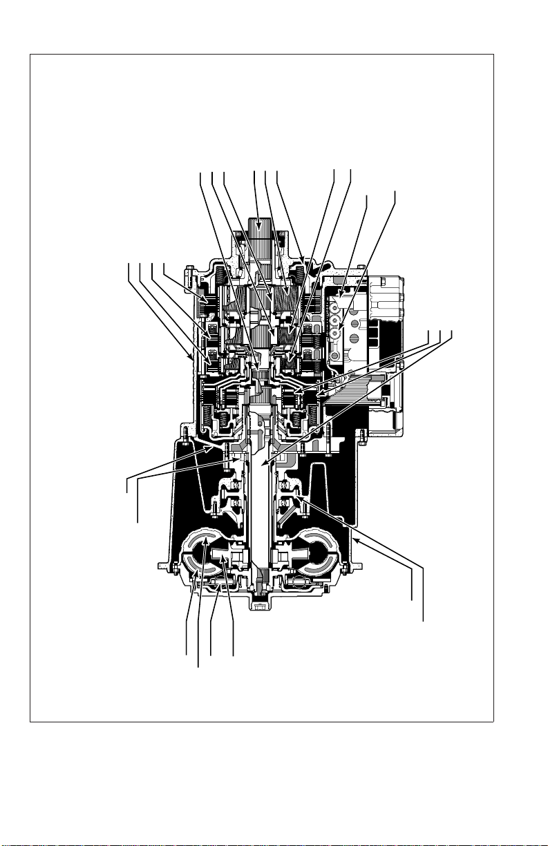
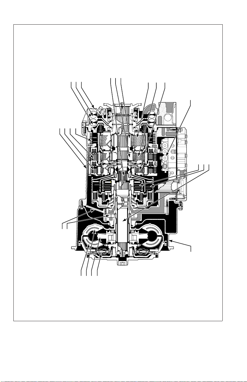
MAIN SHAFT MODULE
• MAIN SHAFT
• P2 SUN
• P3 SUN
MAIN HOUSING MODULE
• MAIN HOUSING
• C3 CLUTCH
• C4 CLUTCH
• C5 CLUTCH
REAR COVER MODULE
• OUTPUT SHAFT
• P3
• C5 PISTON
P2 MODULE
P1 MODULE
CONTROL MODULE
• ELECTRO-HYDRAULIC
CONTROLS
OIL LEVEL SENSOR
ROTATING CLUTCH MODULE
V03350.08.00
• C1 CLUTCH
• C2 CLUTCH
• TURBINE SHAFT
FRONT SUPPORT/OIL PUMP MODULE
• FRONT SUPPORT
• OIL PUMP
CONVERTER MODULE
• TURBINE
• PUMP
• LOCKUP
CLUTCH/DAMPER
• STATOR
CONVERTER HOUSING MODULE
Figure 1–1. 3000 Product Family Transmission
with PTO—Cross Section
8
• CONVERTER HOUSING
• PTO DRIVE GEAR
Page 10
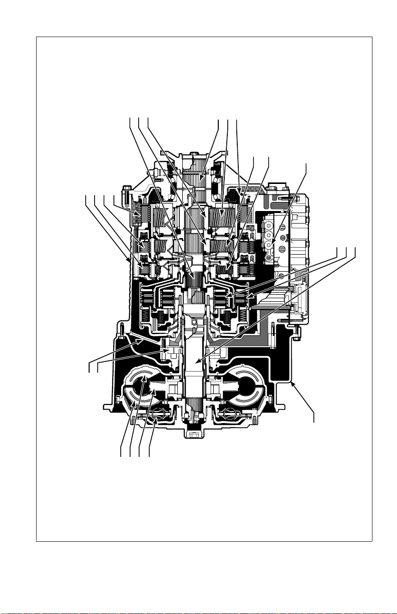
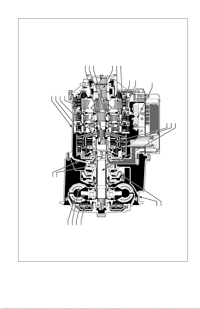
MAIN SHAFT MODULE
MAIN SHAFT
P2 SUN
P3 SUN
MAIN HOUSING MODULE
MAIN HOUSING
C3 CLUTCH
C4 CLUTCH
C5 CLUTCH
REAR COVER MODULE
OUTPUT SHAFT
P3 MODULE
C5 PISTON
P1 MODULE
P2 MODULE
V07286.02.00
CONTROL MODULE
ELECTRO-HYDRAULIC CONTROLS
ROTATING CLUTCH MODULE
C1 CLUTCH
C2 CLUTCH
TURBINE SHAFT
OIL PUMP
FRONT SUPPORT
PUMP
STATOR
LOCKUP
FRONT SUPPORT/OIL PUMP MODULE
TURBINE
CLUTCH/DAMPER
CONVERTER MODULE
CONVERTER HOUSING
CONVERTER HOUSING MODULE
Figure 1–2. 3000 Product Family Transmission—Cross Section
9
Page 11
V07287.06.00
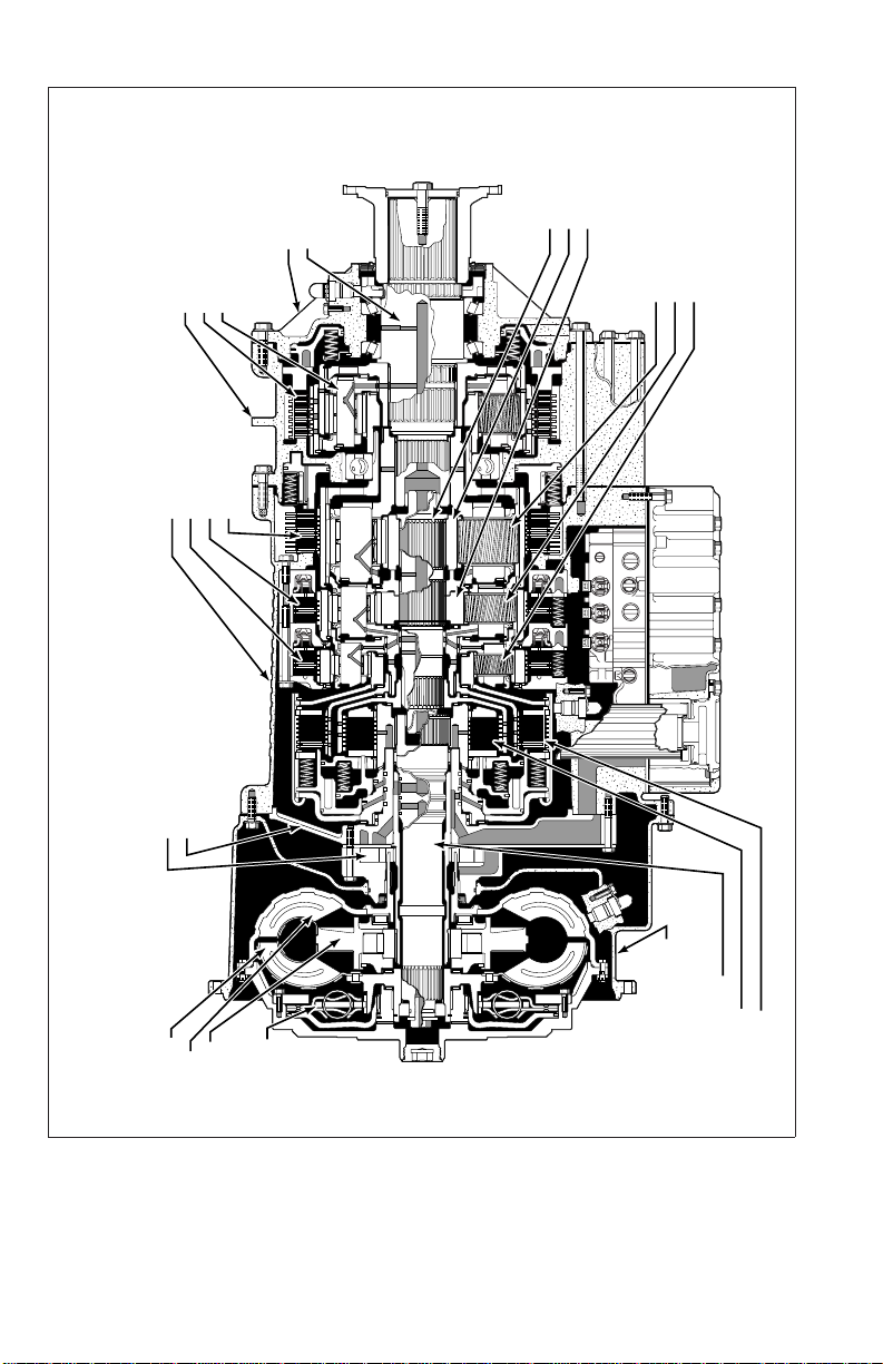
RETARDER MODULE
STATOR ASSEMBLY
ROTOR
HOUSING ASSEMBLY
MAIN HOUSING MODULE
MAIN HOUSING
C3 CLUTCH
C4 CLUTCH
C5 CLUTCH
OIL PUMP
MAIN SHAFT MODULE
MAIN SHAFT
P2 SUN
P3 SUN
P3 MODULE
P2 MODULE
P1 MODULE
CONTROL MODULE
ELECTRO-HYDRAULIC CONTROLS
ROTATING CLUTCH MODULE
C1 CLUTCH
C2 CLUTCH
TURBINE SHAFT
FRONT SUPPORT
PUMP
STATOR
LOCKUP
FRONT SUPPORT/OIL PUMP MODULE
TURBINE
CONVERTER MODULE
CLUTCH/DAMPER
Figure 1–3. 4000 Product Family Transmission
with Retarder—Cross Section
10
CONVERTER HOUSING
CONVERTER HOUSING MODULE
Page 12
MAIN SHAFT MODULE
MAIN SHAFT
MAIN HOUSING MODULE
MAIN HOUSING
C3 CLUTCH
C4 CLUTCH
C5 CLUTCH
OIL PUMP
P2 SUN
P3 SUN
REAR COVER MODULE
OUTPUT SHAFT
P3 MODULE
C5 PISTON
P2 MODULE
P1 MODULE
V07288.03.00
CONTROL MODULE
ELECTRO-HYDRAULIC CONTROLS
ROTATING CLUTCH MODULE
C1 CLUTCH
C2 CLUTCH
TURBINE SHAFT
FRONT SUPPORT
FRONT SUPPORT/OIL PUMP MODULE
PUMP
STATOR
LOCKUP
TURBINE
CONVERTER MODULE
CLUTCH/DAMPER
CONVERTER HOUSING MODULE
Figure 1–4. 4000 Product Family Transmission
with PTO—Cross Section
11
PTO DRIVE GEAR
CONVERTER HOUSING
Page 13
GNISUOH RETPADA 6C •
GNISUOH RETPADA 6C
ELUDOM
ELUDOM GNISUOH NIAM
GNISUOH NIAM •
ELUDOM PMUP LIO/TROPPUS TNORF
TROPPUS TNORF •
PMUP LIO •
REVOC RAER
ELUDOM
ELUDOM 4P •
•REVOC RAER
•TFAHS TUPTUO
•HCTULC 6C
HCTULC 3C •
HCTULC 4C •
HCTULC 5C •
TFAHS NIAM
NUS 3P •
NUS 2P •
ELUDOM
•TFAHS NIAM
ELUDOM 3P
V05641.03.00
ELUDOM 2P
ELUDOM 1P
ELUDOM RETREVNOC
ENIBRUT •
PUKCOL •
REPMAD
ROTATS •
PMUP •
/HCTULC
Figure 1–5. 4000 Product Family Transmission
7-Speed—Cross Section
12
ELUDOM HCTULC GNITATOR
ELUDOM GNISUOH
RETREVNOC
TFAHS ENIBRUT •
HCTULC 1C •
HCTULC 2C •
•GNISUOH RETREVNOC
Page 14
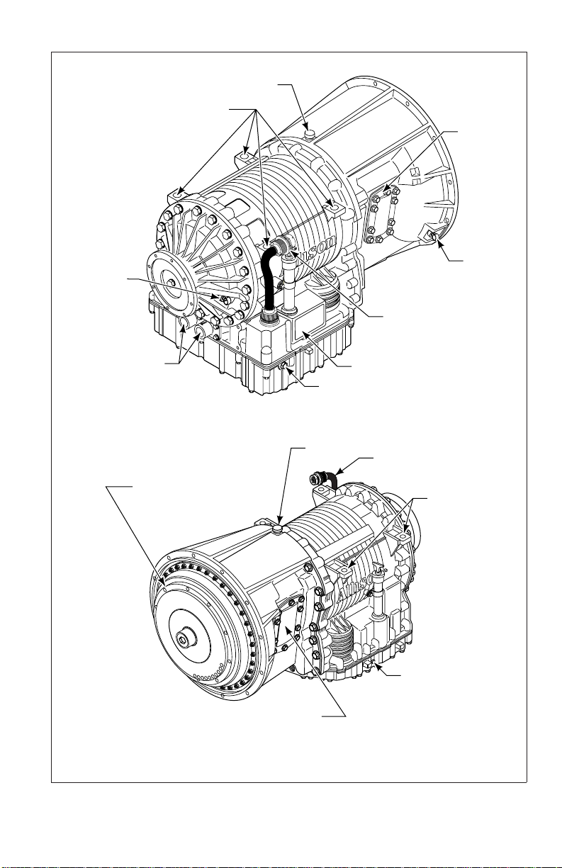
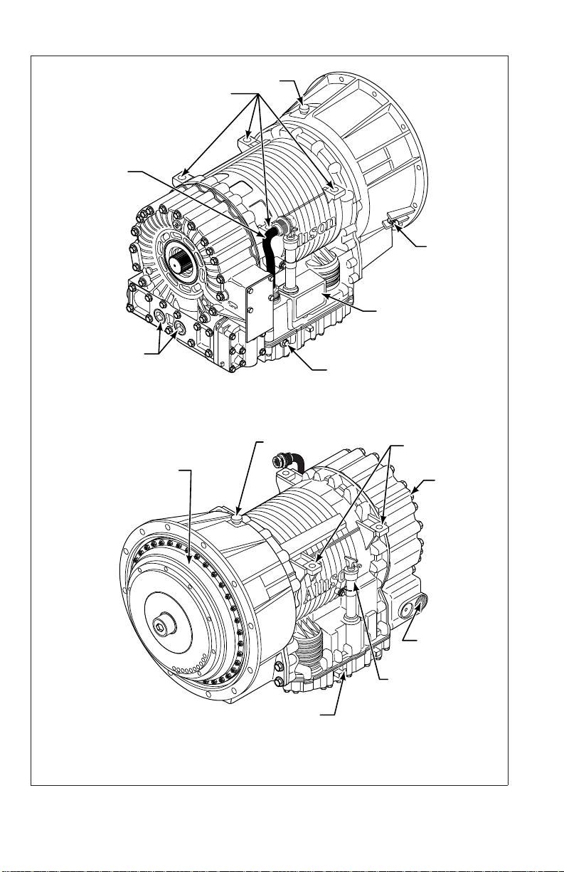
OUTPUT
SPEED
SENSOR
BREATHER
ASSEMBLY PADS
PTO
PROVISION
INPUT
SPEED
SENSOR
FEEDTHROUGH HARNESS
CONNECTOR
COOLER PORTS
NOTE: Inch Series Threads
TORQUE CONVERTER
WITH LOCKUP CLUTCH
AND TORSIONAL DAMPER
MAIN-PRESSURE TAP
NOTE: Inch Series Threads
RIGHT-REAR VIEW
BREATHER
PTO PROVISION
(AVAILABLE BOTH SIDES)
LEFT-FRONT VIEW
NAMEPLATE
FEEDTHROUGH HARNESS
CONNECTOR
ASSEMBLY PADS
(BOTH SIDES)
MAIN-PRESSURE TAP
NOTE: Inch Series Threads
V07289.02.00
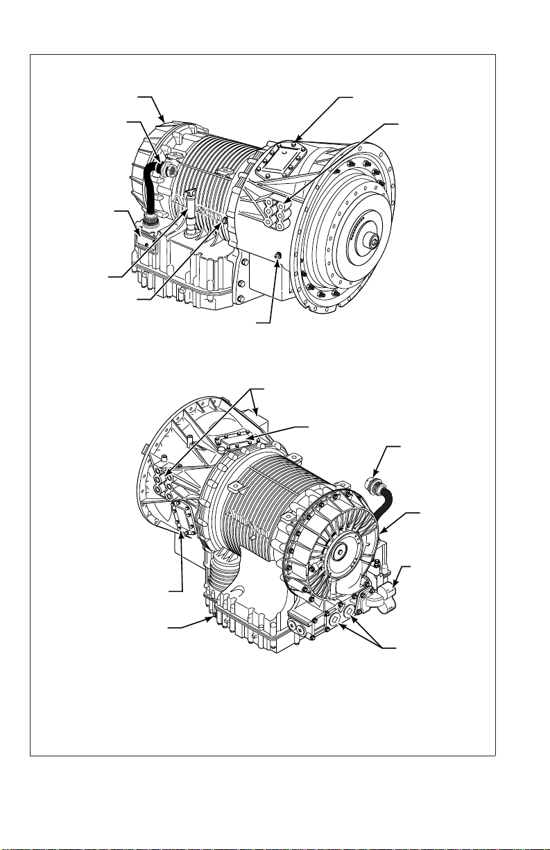
Figure 1–6. 3000 Product Family Transmission with PTO
13
Page 15
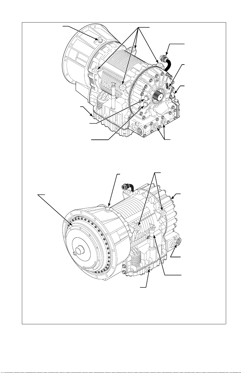
FEEDTHROUGH
HARNESS
CONNECTOR
COOLER PORTS
NOTE: Inch Series Threads
ASSEMBLY PADS
BREATHER
INPUT SPEED
SENSOR
NAMEPLATE
MAIN-PRESSURE TAP
NOTE: Inch Series Threads
RIGHT-REAR VIEW
BREATHER
TORQUE CONVERTER
WITH LOCKUP CLUTCH
AND TORSIONAL DAMPER
MAIN-PRESSURE TAP
NOTE: Inch series threads
ASSEMBLY PADS
(BOTH SIDES)
TO RETARDER
ACCUMULATOR
OIL FILL TUBE AND
DIPSTICK
(AVAILABLE ON
BOTH SIDES
LEFT-FRONT VIEW
Figure 1–7. 3000 Product Family Transmission with Retarder
14
OUTPUT
RETARDER
)
V07290.01.00
Page 16
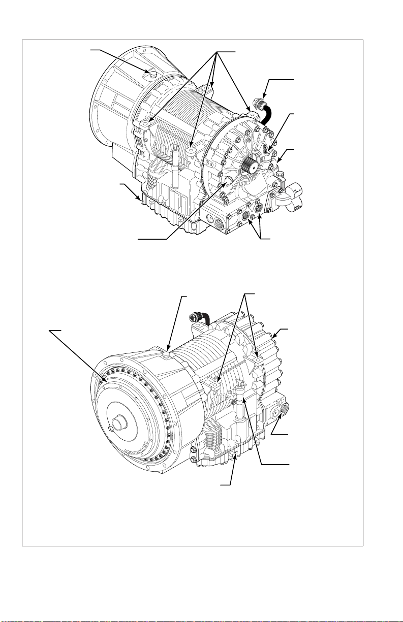
BREATHER
MAIN-PRESSURE TAP
NOTE: Inch Series Threads
TACHOGRAPH PROVISION
NOTE: Metric Series Threads
ASSEMBLY PADS
FEEDTHROUGH
HARNESS
CONNECTOR
OUTPUT
SPEED
SENSOR
RETARDER
VALVE BODY
CONNECTOR
SPEEDOMETER PROVISION
NOTE: Inch Series Threads
LEFT-REAR VIEW
TORQUE CONVERTER
WITH LOCKUP CLUTCH
AND TORSIONAL DAMPER
MAIN-PRESSURE TAP
LEFT-FRONT VIEW
BREATHER
NOTE: Inch series threads
COOLER PORTS
NOTE: Inch Series Threads
ASSEMBLY PADS
(BOTH SIDES)
OUTPUT
RETARDER
TO RETARDER
ACCUMULATOR
OIL FILL TUBE
AND DIPSTICK
(AVAILABLE ON
BOTH SIDES
V07300.01.00
)
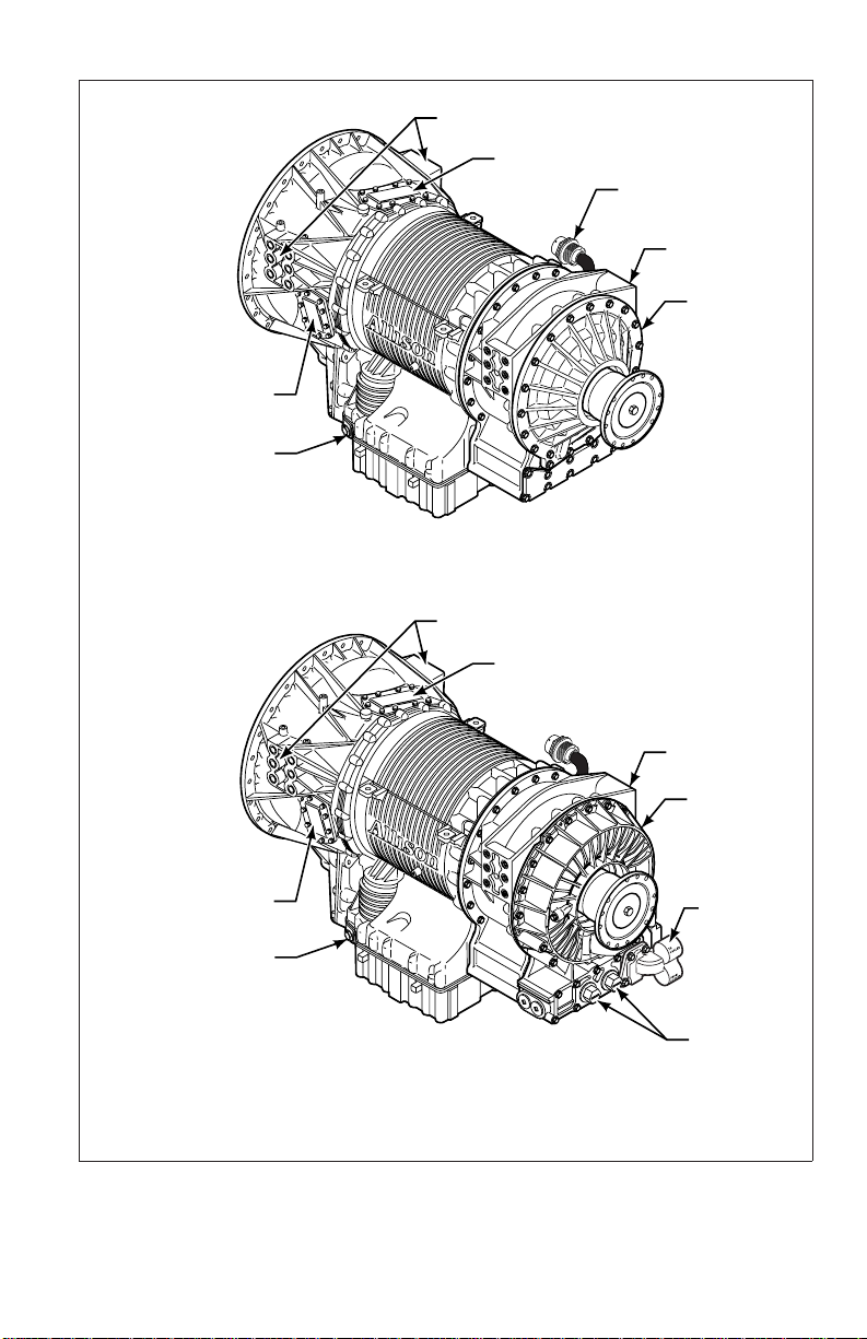
Figure 1–8. 3000 Product Family Transmission with Retarder and
Provisions for Tachograph and Speedometer
15
Page 17
BREATHER
MAIN-PRESSURE TAP
NOTE: Inch Series Threads
ASSEMBLY PADS
FEEDTHROUGH
HARNESS
CONNECTOR
OUTPUT
SPEED
SENSOR
RETARDER
VALVE BODY
CONNECTOR
TACHOGRAPH PROVISION
NOTE: Inch Series Threads
LEFT-REAR VIEW
TORQUE CONVERTER
WITH LOCKUP CLUTCH
AND TORSIONAL DAMPER
LEFT-FRONT VIEW
BREATHER
MAIN-PRESSURE TAP
NOTE: Inch series threads
COOLER PORTS
NOTE: Inch Series Threads
ASSEMBLY PADS
(BOTH SIDES)
OUTPUT
RETARDER
TO RETARDER
ACCUMULATOR
OIL FILL TUBE
AND DIPSTICK
(AVAILABLE ON
BOTH SIDES
V07401.02.00
)
Figure 1–9. 3000 Product Family Transmission with Retarder and
Provisions for Tachograph and Sump Cooler
16
Page 18
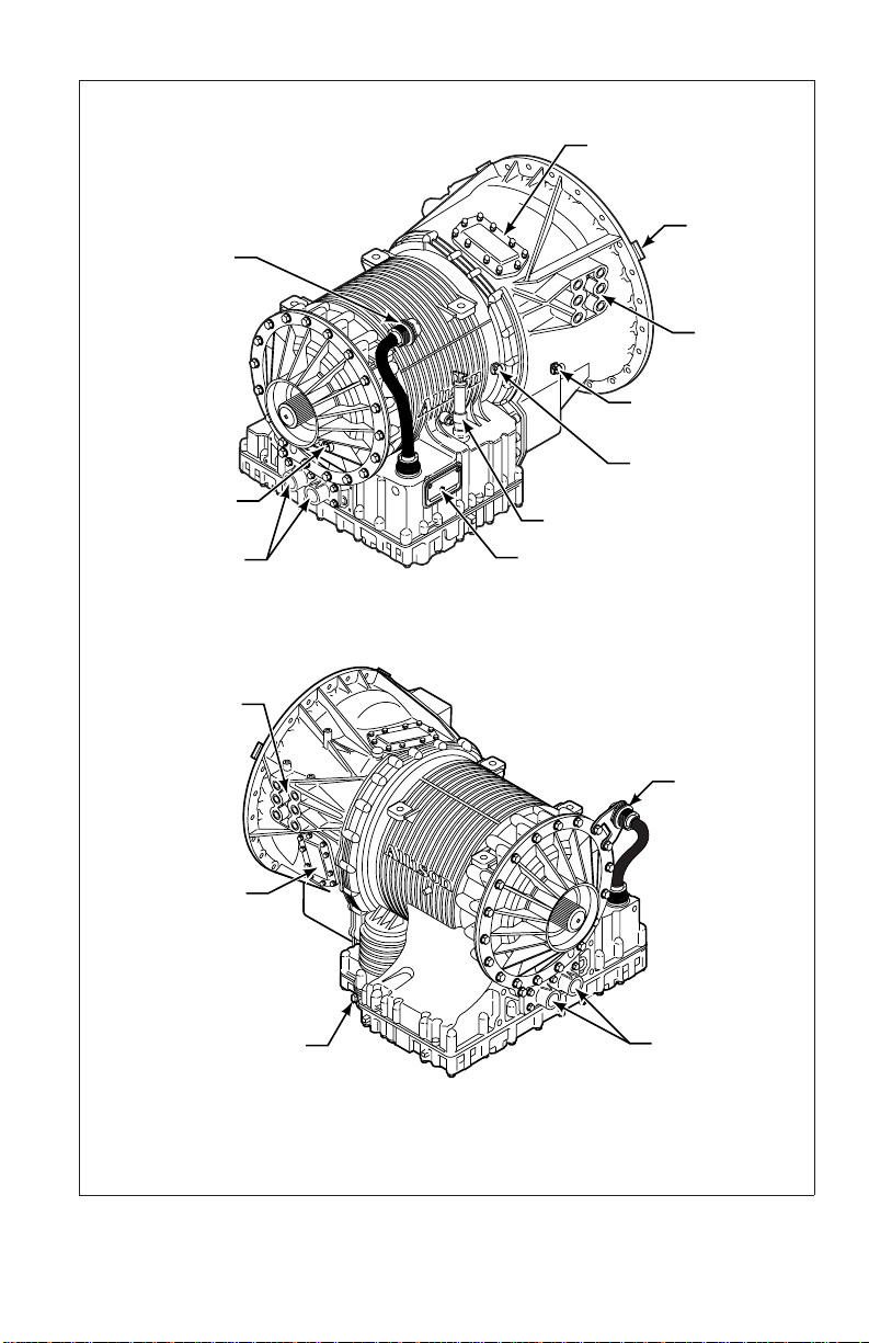
FEEDTHROUGH
HARNESS
CONNECTOR
OUTPUT SPEED
SENSOR
COOLER PORTS
MOUNTING PAD
(BOTH SIDES)
PTO
(TOP RIGHT POSITION)
SHIPPING
BRACKET (3)
MOUNTING
PAD
ENGINE SPEED
SENSOR
TURBINE SPEED
SENSOR
FILL TUBE
NAMEPLATE
RIGHT-REAR VIEW
FEEDTHROUGH
HARNESS
CONNECTOR
(BOTTOM LEFT
MAIN-PRESSURE TAP
PTO
POSITION)
COOLER PORTS
LEFT-REAR VIEW
Figure 1–10. 4000 Product Family Transmission with PTO
17
V07291.00.01
Page 19
RETARDER
PTO (TOP RIGHT POSITION)
FEEDTHROUGH
HARNESS
CONNECTOR
NAMEPLATE
FILL TUBE
TURBINE
SPEED
SENSOR
MOUNTING PADS
(BOTH SIDES)
ENGINE SPEED SENSOR
RIGHT-FRONT VIEW
MOUNTING PADS
(BOTH SIDES)
PTO (TOP RIGHT POSITION)
FEEDTHROUGH
HARNESS
CONNECTOR
RETARDER
SUMP
COOLER
PTO (BOTTOM LEFT
POSITION)
MAIN-PRESSURE TAP
PROVISION
COOLER PORTS
LEFT-REAR VIEW
V07292.03.00
Figure 1–11. 4000 Product Family Transmission with Retarder and PTO
18
Page 20
MOUNTING PADS
(BOTH SIDES)
PTO (TOP RIGHT POSITION)
FEEDTHROUGH
HARNESS
CONNECTOR
C6 ADAPTER
HOUSING
REAR COVER
PTO (BOTTOM LEFT
POSITION)
MAIN-PRESSURE TAP
PTO (BOTTOM LEFT
POSITION)
MAIN-PRESSURE TAP
LEFT-REAR
MOUNTING PADS
(BOTH SIDES)
PTO (TOP RIGHT POSITION)
C6 ADAPTER
HOUSING
RETARDER
SUMP
COOLER
PROVISION
COOLER
PORTS
LEFT-REAR
V07399.00.02
Figure 1–12. 4000 Product Family 7-Speed Transmission
with PTO (Top) and 7-Speed with PTO and Retarder (Bottom)
19
Page 21
Section II
2–1. PERIODIC INSPECTION AND CARE
Clean and inspect the exterior of the transmission at regular intervals. Severity of
service and operating conditions determine the frequency of these inspections.
Inspect the transmission for:
• Loose bolts—transmission and mounting components
• Fluid leaks—repair immediately
• Loose, dirty, or improperly adjusted throttle sensor
• Damaged or loose hoses
• Worn, frayed, or improperly routed electrical harnesses
• Worn or frayed electrical connections
• Dented, worn or out-of-phase driveline U-joints and slip fittings
• Clogged or dirty breather
Inspect the vehicle cooling system occasionally for evidence of transmission fluid.
Transmission fluid in the vehicle cooling system indicates a faulty oil cooler.
CAUTION: When welding on the vehicle:
• DO NOT WELD on the vehicle without disconnecting all control
system wiring harness connectors from the ECU.
• DO NOT WELD on the vehicle without disconnecting ECU
battery power and ground leads.
• DO NOT WELD on any control components.
• DO NOT CONNECT welding cables to any control components.
PREVENTIVE
MAINTENANCE
A label (ST2067EN) describing on-vehicle welding precautions is available from
your authorized Allison service dealer and should be installed in a conspicuous
place. A vehicle used in a vocation that requires frequent modifications or repairs
involving welding must have an on-vehicle welding label.
2–2. IMPORTANCE OF PROPER TRANSMISSION FLUID LEVEL
Transmission fluid cools, lubricates, and transmits hydraulic power. Always
maintain proper fluid level. If fluid level is too low, the torque converter and
clutches do not receive an adequate supply of fluid and the transmission overheats.
20
Page 22

If the level is too high, the fluid aerates—causing the transmission to shift
erratically and overheat. Fluid may be expelled through the breather or dipstick
tube when the fluid level is too high.
2–3. TRANSMISSION FLUID TEST
a. Electronic Fluid Test Procedure. Fluid level can be electronically displayed
on a pushbutton (non-strip type) shift selector, lever shift selector, or Allison
DOC™ For PC–Service Tool if there is an oil level sensor (OLS) installed and
“autodetected” by the WTEC III control system. Frequently test for the presence
of oil level diagnostics if the transmission is known to contain an OLS.
If an OLS is not detected during the first 49 engine starts, the WTEC III system
concludes that no OLS is present. If an OLS is known to be present, but has not
been “autodetected”, then troubleshoot the OLS circuit.
After the OLS circuit is repaired, reset “autodetect” or manually select the OLS
function using the Allison DOC™ service tool and then reset autodetect (refer to
TS2973EN, WTEC III Troubleshooting Manual for detailed troubleshooting
procedures).
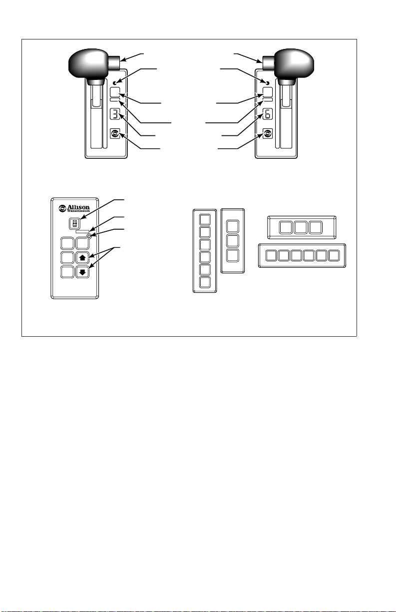
• Displaying Fluid Level Information. Use the following procedure to display
fluid level information (refer to Figure 2–1).
— For a pushbutton shift selector: Simultaneously press the ↑ (Up) and
↓ (Down) arrow buttons once.
— For a lever shift selector: Press the DISPLAY MODE/DIAGNOSTIC
button once.
— For Allison DOC™ For PC–service tool: Connect the Allison DOC™
For PC–service tool to the diagnostic tool connector on the wiring
harness and scroll down the DIAGNOSTIC DATA LIST to read the
OLS information.
• Fluid Level Display Criteria. As soon as fluid level information is
requested, the ECU determines if conditions are right to allow display.
Certain operating conditions must have been met for a period of two
minutes before fluid level is displayed. These operating conditions are:
— Engine at idle
— Sump fluid at operating temperature 60–104°C (140–220°F)
— Transmission output shaft stopped
— Transmission in neutral
— OLS functioning properly
21
Page 23
HOLD OVERRIDE BUTTON
1
MODE
2
3
4
5
D
N
R
DIGITAL DISPLAY
DIAGNOSTIC BUTTON
SIX-SPEED, LEFT-HAND
LEVER SELECTOR
MODE INDICATOR
(LED)
MODE BUTTON
MODE ID
✽
DISPLAY MODE/
SIX-SPEED, RIGHT-HAND
R
MODE
N
D
5
4
3
2
1
LEVER SELECTOR
DIGITAL DISPLAY
MODE ID
MODE
MODE
R
N
D
INDICATOR (LED)
Push simultaneously
to enter diagnostic
mode and fluid level
check (optional)
PUSHBUTTON
SELECTOR
✽
NOTE:
Number displayed is highest forward range available in selected position.
Visually check to confirm range selected. If display is flashing – shift is inhibited.
✽
1
D
2
N
3
R
D
213DNR
R
D
N
N
R
STRIP PUSHBUTTON
SHIFT SELECTORS
V03496.02
Figure 2–1. Typical Shift Selectors
Information is displayed immediately if the two minute time period elapsed before
a fluid level data request was made. However, if the two minute period has not
elapsed, there will be a countdown display before fluid level information displays.
The countdown display flashes constantly. Countdown starts at 8 and decreases
sequentially to 1 during the two minute period. When fluid level data is requested,
and the two minute countdown is in process, the flashing display shows the
number corresponding to the countdown progress.
For example:
• If the fluid level data was requested in the middle of the two minute
countdown period, the display would flasha5ora4anddecrease to 1.
• Shift Selector Display. Fluid level information is displayed one character at
a time as in Table 2–1:
22
Page 24
Table 2–1. Fluid Level Shift Selector Display
Display Sequence Interpretation of Display
o L o K Fluid level is correct
o L L o 1 Fluid level is 1 quart low
o L H I 1 Fluid level is 1 quart high
The shift selector display will also show “invalid for display” codes one character
at a time. An “invalid for display” code is returned when fluid level data is
requested, but an operational condition has not been met. The “invalid for display”
condition interrupts the two minute countdown (momentary increase in engine
speed does not affect the countdown). The “invalid for display” codes and their
meaning are:
Table 2–2. Invalid For Display Codes
Display Sequence Interpretation of Display
o L – 5 0 Engine rpm too low
o L – 5 9 Engine rpm too high
oL –6 5 N (Neutral) not selected
o L – 7 0 Sump fluid temperature too low
o L – 7 9 Sump fluid temperature too high
o L – 8 9 Output shaft rotation
o L – 9 5 Sensor failure
NOTE: Report sensor failure to a distributor or dealer in your area.
Consult the telephone directory for the Allison Transmission distributor
or dealer near you.
The countdown is restarted when the condition causing the “invalid for display”
code 59 has been corrected. The countdown is not restarted if there is a
momentary increase in engine rpm which may generate a code 59. “Invalid for
display” messages are as follows:
• Allison DOC™ Display. “Invalid for display” messages are displayed in the
Oil (±) field of the Data Monitor.
Allison DOC™ Message
OL — SETTLING TIME X
OL — ENGINE SPEED LO
OL — ENGINE SPEED HI
OL — SELECT N (NEUTRAL)
OL — SUMP TEMP LO
23
Page 25

Allison DOC™ Message
OL — SUMP TEMP HI
OL — OUTPUT SPEED HI
OL — CHECK CODES
• Exiting the Fluid Level Mode. Exit as follows:
— For a pushbutton shift selector, press the N (Neutral) pushbutton once.
— For a lever selector, press the DISPLAY MODE/DIAGNOSTIC
button once or move the lever to a range position.
— Allison DOC™ does not use a special Fluid Level Mode.
b. Manual Fluid Test Procedure.
WARNING: To help avoid personal injury or property damage caused
by sudden and unexpected vehicle movement, do not determine the
fluid level until you:
1. Put the transmission into N (Neutral).
2. Apply the parking brake and emergency brakes and make sure
they are properly engaged.
3. Chock the wheels and take any other steps necessary to keep the
vehicle from moving.
Clean all dirt from around the end of the fluid fill tube before removing the
dipstick. Do not allow dirt or foreign matter to enter the transmission. Dirt or
foreign matter in the hydraulic system may cause undue wear of transmission
parts, make valves stick, and clog passages. Determine the fluid level using the
following procedure and report any abnormal fluid levels to your service
management.
c. Cold Test Procedure. The purpose of the cold test is to determine if the
transmission has enough fluid to be safely operated until a hot test can be made.
CAUTION: The fluid level rises as fluid temperature increases. DO
NOT fill above the “COLD CHECK” band if the transmission fluid is
below normal operating temperature. During operation, an over full
transmission can become overheated, leading to transmission damage.
1. Park the vehicle on a level surface. Apply the parking brake and chock the
wheels.
2. Run the engine for at least one minute. Shift to D (Drive), then to
N (Neutral), and then to R (Reverse) to fill the hydraulic system.
3. Shift to N (Neutral) and allow the engine to idle (500–800 rpm).
24
Page 26

4. With the engine running, remove the dipstick from the tube and wipe the
dipstick clean.
5. Insert the dipstick into the tube until it stops and then remove. Read the
fluid level. Repeat the test procedure to verify the reading.
6. If the fluid level is between the “COLD ADD” and the “COLD FULL”
bands (refer to Figure 2–2), the transmission may be operated until the fluid
is hot enough to perform a “HOT RUN” test. If the fluid level is not
between the “COLD ADD” and the “COLD FULL” bands, add or drain
fluid as necessary to bring it to the middle of this level.
7. Perform a hot test at the first opportunity after the normal operating sump
temperature of 71°C–93°C (160°F–200°F) is reached.
d. Hot Test Procedure.
CAUTION: The fluid level rises as temperature increases. The fluid
must be hot to be sure of an accurate test.
1. Operate the transmission in D (Drive) until normal operating temperatures
are reached:
— Sump temperature 71°C–93°C (160°F–200°F)
— Converter-out temperature 82°C–104°C (180°F–220°F)
2. Park the vehicle on a level surface and shift to N (Neutral). Apply the
parking brake and chock the wheels. Allow the engine to idle
(500–800 rpm).
3. With the engine running, remove the dipstick from the tube and wipe clean.
4. Insert the dipstick into the tube until it stops. Then remove it. Read fluid
level.
5. Repeat the test procedure to verify the reading.
NOTE: Safe operating level is within the “HOT RUN” band on the
dipstick. The “HOT RUN” band is between the “HOT FULL” and the
“HOT ADD” bands. Refer to Figure 2–2.
• If the fluid level is not between the HOT FULL and HOT ADD bands
(refer to Figure 2–2), add or drain fluid as necessary to bring the fluid level
within these bands.
e. Consistency of Readings. Always determine the fluid level at least twice,
with the engine running. Consistency (repeatable readings) is important to
maintaining accuracy of the readings. If inconsistent readings persist, inspect the
transmission breather to be sure it is clean and unclogged.
25
Page 27

3000 PRODUCT FAMILY 4000 PRODUCT FAMILY
6.35 mm (0.250 in.) REFERENCE
Blade can be as narrow as
4.76 mm (0.187 in.).
FULL
HOT
FULL
FILL
HOT
TUBE
ADD
HOT
FILL
TUBE
COLD
FULL
A
B
COLD
ADD
C
F
TRANSMISSION CONTROL MODULE
OIL SUMP
2.00 in. and
4.00 in.****
2.00 in.***
4.00 in.*** 3000 PRODUCT FAMILY
TRANSMISSION/SUMP
DESCRIPTION
4000 PRODUCT FAMILY
3000 PRODUCT FAMILY
D
E
SPLIT LINE
DIMENSION
A
106.7 mm
(4.20 in.)
101.6 mm
(4.00 in.)
101.6 mm
(4.00 in.)
A
DIMENSION
B
76.2 mm
(3.00 in.)
73.7 mm
(2.90 in.)
63.5 mm
(2.50 in.)
B
DIMENSION
ADD
HOT
COLD
FULL
COLD
C
ADD
D
F
DIMENSIONDDIMENSIONEDIMENSION
C
66.0 mm
(2.60 in.)
50.8 mm
(2.00 in.)
45.7 mm
(1.80 in.)
*
*
*
E
132.6 mm
(5.22 in.)
86.6 mm
(3.41 in.)
86.6 mm
(3.41 in.)
NOTE: Calibrate level marking locations with respect to transmission control module
split line and fill tube.
Scale none.
*Dimension determined by installation.
**Reference dimension only. Actual dimension to be determined by installation.
***Reference drawing AS66-460.
****Reference drawing AS67-460.
F**
13.8 mm
(0.54 in.)
5.9 mm
(0.23 in.)
5.9 mm
(0.23 in.)
V07301.00.05
Figure 2–2. Standard 3000 And 4000 Product Families Dipstick
Markings
26
Page 28

2–4. KEEPING FLUID CLEAN
Prevent foreign material from entering the transmission by using clean containers,
fillers, etc. Lay the dipstick in a clean place while filling the transmission.
CAUTION: Containers or fillers that have been used for antifreeze
solution or engine coolant must NEVER be used for transmission fluid.
Antifreeze and coolant solutions contain ethylene glycol which, if put
into the transmission, can cause the clutch plates to fail.
2–5. FLUID RECOMMENDATIONS
The hydraulic fluid (oil) used in the transmission directly affects transmission
performance, reliability, and durability. Customers may continue to choose from a
®
wide variety of approved DEXRON
–III or Allison qualified C4 fluids. Customers
may elect to use TranSynd™ or TES 295 equivalent and extend drain-intervals.
Equivalent TranSynd™ fluid must meet or exceed TES 295 specifications.
TranSynd™ is a fully synthetic transmission fluid developed by Allison
Transmission and Castro, Ltd. and is fully qualified to the GM TES 295
specifications.
DEXRON
®
-III fluids are also acceptable for off-highway applications. To be sure
a fluid is qualified for use in Allison transmissions, look for fluid license or
approval numbers on the container, or consult the lubricant manufacturer. Consult
your Allison Transmission dealer or distributor before using other fluid types.
CAUTION: Disregarding minimum fluid temperature limits can result
in transmission malfunction or reduced transmission life.
When choosing the optimum viscosity grade of fluid, duty cycle, preheat
capabilities, and/or geographical location must be taken into consideration. Table
2–4 lists the minimum fluid temperatures at which the transmission may be safely
operated without preheating the fluid. Preheat with auxiliary heating equipment or
by running the equipment or vehicle with the transmission in neutral for a
minimum of 20 minutes before attempting range operation.
Table 2–4. Transmission Fluid Operating Temperature Requirements
Ambient Temperature Below Which Preheat
is Required
Viscosity Grade Celsius Fahrenheit
TranSynd™/SAE 0W–20
DEXRON
®
–III –25 –13
* –30 –22
SAE 10W –20 –4
27
Page 29

Table 2–4. Transmission Fluid Operating Temperature Requirements
(cont’d)
Ambient Temperature Below Which Preheat
is Required
Viscosity Grade Celsius Fahrenheit
SAE 15W–40 –15 5
SAE 30W 0 32
SAE 40W 10 50
* “Arctic” as defined by MIL-L-46167B (Ref. SIL 13-TR-90)
2–6. TRANSMISSION FLUID AND FILTER CHANGE INTERVALS
a. Frequency.
CAUTION: Transmission fluid and filter change frequency is
determined by the severity of transmission service. More frequent
changes may be necessary than recommended in the general guidelines
when operating conditions create high levels of contamination or
overheating.
Table 2–5 and Table 2–6, Recommended Fluid/Filter Change Intervals, is a
general guide for fluid and filter change intervals.
28
Page 30

Lube/
Auxiliary
(40 000 km)
12 Months
1000 Hours
(120 000 km)
36 Months
3000 Hours
Filters***
Fluid†
Lube/
Auxiliary Main Internal
Filters***
Overhaul 25,000 Miles
(40 000 km)
25,000 Miles
(40 000 km)
25,000 Miles
(20 000 km)
Overhaul 12,000 Miles
12 Months
1000 Hours
12 Months
1000 Hours
6 Months
500 Hours
Overhaul 75,000 Miles
75,000 Miles
(120 000 km)
(240 000 km)
150,000 Miles
(120 000 km)
Overhaul 75,000 Miles
Schedule 2. TranSynd™/TES 295 Fluid (2 or 4 inch control module)
36 Months
3000 Hours
48 Months
4000 Hours
36 Months
3000 Hours
Table 2–5. Recommended Fluid/Filter Change for 3000 Product Family
SEVERE VOCATION* GENERAL VOCATION**
Schedule 1. Non-TranSynd™/Non-TES 295 Fluid (2 or 4 inch control module)
Main Internal
Fluid†
INITIAL FILTER CHANGE INTERVAL:Main/Lube—5000 miles (8000 km) / 200 hours.
(20 000 km)
12,000 Miles
(20 000 km)
12,000 Miles
6 Months
500 Hours
6 Months
500 Hours
Recommendations in Schedule 2 are based upon the transmission containing 100 percent TranSynd™ or TES 295 fluid.
3000 Product Family filter change intervals in Schedule 2 are only valid with the use of Allison Gold series filters.
Flushing machines are not recommended or recognized due to variation and inconsistencies with assuring removal of
100 percent of the used fluid.
29
75,000 Miles
(120 000 km)
75,000 Miles
(120 000 km)
36 Months
3000 Hours
36 Months
3000 Hours
* Severe Vocation: All retarders, On/Off-Highway, Refuse, Transit, and Intercity Coach with duty cycle greater than one stop per mile.
change intervals of Allison Transmission. Transmission protection and fluid change intervals can be optimized by the use of fluid analysis.
** General Vocation: Intercity Coach with duty cycle less than or equal to one stop per mile and all other vocations not listed in severe vocation
† Local conditions, severity of operation, or duty cycle may require more or less frequent change intervals that differ from the published recommended fluid
*** Filters must be changed at or before recommended mileage, months, or elapsed hour intervals (whichever occurs first).
Page 31

Lube/
Auxiliary
(40 000 km)
12 Months
1000 Hours
36 Months
(120 000 km)
3000 Hours
Filters***
Fluid†
Lube/
Auxiliary Main Internal
Filters***
Overhaul 25,000 Miles
(40 000 km)
25,000 Miles
(40 000 km)
25,000 Miles
(20 000 km)
Overhaul 12,000 Miles
12 Months
1000 Hours
12 Months
1000 Hours
6 Months
500 Hours
Overhaul 75, 000 Miles
75,000 Miles
(120 000 km)
(240 000 km)
150,000 Miles
(120 000 km)
Overhaul 75,000 Miles
36 Months
3000 Hours
48 Months
4000 Hours
36 Months
3000 Hours
SEVERE VOCATION* GENERAL VOCATION**
Table 2–6. Recommended Fluid/Filter Change Intervals For 4000 Product Family
Main Internal
Schedule 1. Recommended Fluid and Filter Change Intervals (Non-TranSynd™/Non-TES 295 Fluid)
Fluid†
INITIAL FILTER CHANGE INTERVAL: Main/Lube—5000 miles (8000 km) / 200 hours
(20 000 km)
12,000 Miles
(20 000 km)
12,000 Miles
6 Months
500 Hours
6 Months
500 Hours
NOTE: The following recommendations in Schedule 2 and 3 based upon the transmission containing 100 percent
TranSynd™ or TES 295 fluid. Filter change intervals are valid only if Allison Transmission supplied filters are used.
4000 Product Family filter change intervals in Schedule 2 and 3 are valid only with the use of Allison Transmission Gold
series filters.
36 Months
4 inch Control Module (3.5 inch approximately)—Requires filter kit P/N 29540494
75,000 Miles
(120 000 km)
3000 Hours
Schedule 2. Recommended Fluid and Filter Change Intervals (TranSynd™/TES 295 Fluid)
36 Months
(120 000 km)
3000 Hours
Flushing machines are not recommended or recognized due to variation and inconsistencies with assuring removal of
100 percent of the used fluid.
30
75,000 Miles
Page 32

(cont’d)
Lube/
Auxiliary
(80 000 km)
24 Months
2000 Hours
Filters***
Fluid†
Lube/
Auxiliary Main Internal
Filters***
Overhaul 50,000 Miles
(80 000 km)
50,000 Miles
(240 000 km)
150,000 Miles
(80 000 km)
Overhaul 50,000 Miles
24 Months
2000 Hours
48 Months
4000 Hours
24 Months
2000 Hours
SEVERE VOCATION* GENERAL VOCATION**
Table 2–6. Recommended Fluid/Filter Change Intervals For 4000 Product Family
Main Internal
2 inch Control Module (1.75 inch approximately)—Requires filter kit P/N 29540493
Fluid†
50,000 Miles
Schedule 3. Recommended Fluid and Filter Change Intervals (TranSynd™/TES 295 Fluid)
50,000 Miles
(80 000 km)
(80 000 km)
24 Months
2000 Hours
24 Months
2000 Hours
* Severe Vocation: All retarders, On/Off-Highway, Refuse, Transit, and Intercity Coach with duty cycle greater than one stop per mile.
** General Vocation: Intercity Coach with duty cycle less than or equal to one stop per mile.
fluid change intervals of Allison Transmission. Transmission protection and fluid change intervals can be optimized by the use of fluid analysis.
† Local conditions, severity of operation, or duty cycle may require more or less frequent change intervals that differ from the published recommended
*** Filters must be changed at or before recommended mileage, months, or elapsed hour intervals (whichever occurs first).
31
Page 33

b. Abnormal Conditions. Transmission fluid must be changed whenever there
is evidence of dirt in the fluid or the fluid is discolored, which indicates a high
temperature condition. Fluid analysis will also reveal a high temperature condition.
Local conditions, severity of operation, or duty cycle may require more or less
frequent fluid or filter changes.
c. Fluid Analysis. Transmissions used in high cycle rate applications should
have a fluid analysis performed to be sure of the proper change interval.
Transmission protection and fluid change intervals can be optimized by monitoring
fluid oxidation according to the tests and limits shown in Table 2–7. Consult your
local telephone directory for fluid analysis firms. To be sure of consistent and
accurate fluid analysis, use only one fluid analysis firm. Refer to the Technician’s
Guide for Automatic Transmission Fluid, GN2055EN, for additional information.
Table 2–7. Fluid Oxidation Measurement Limits
Test Limit
Viscosity ±25% change from new fluid
Total Acid Number +3.0
* change from new fluid
Solids 2 percent by volume maximum
* mg of potassium hydroxide (KOH) to neutralize a gram of fluid.
2–7. TRANSMISSION FLUID CONTAMINATION
a. Fluid Examination. The presence of fluid contamination in an automatic
transmission can be detrimental to continued operation. A normal amount of
condensation will appear in the fluid during operation. At each fluid change,
examine the drained fluid for evidence of dirt or water. Contamination limits are
shown in Table 2–8.
Contaminant Limit
Water 0.2% maximum
Glycol No trace allowed
Alien fluids
* Any fluid not included on the Allison Approved Fluid List. The Approved Fluids Lists may be
found at the Allison Transmission website, www.allisontransmission.com.
* If detected, change transmission fluid
b. Monitoring Wear. Absolute maximum values cannot be applied to wear
metals of an automatic transmission due to the many variables present that affect
concentration limits. Wear metal analysis results must be evaluated using a
trendline approach.
A trendline approach plots the concentration level of each wear metal over a
period of time. A minimum of four data points for each metal is required to
establish a trendline. A line of “best fit” drawn through the plotted points is
32
Page 34

considered a trendline. Cause for concern should only occur when significant
deviations in the established trendline are present.
While trendline analysis on wear metals can prove informative and useful, a
transmission removal decision should not be based solely upon the analysis. A
removal based solely on wear metal analysis may result in an unnecessary tear
down. The results should be used in conjunction with other inspection procedures
such as functional check, road test, or fluid sump/internal filter inspection.
Transmission removal should occur only if the additional investigation warrants
it.
c. Water/Engine Coolant Contaminant.
NOTE: Cooler water can be contaminated by engine oil. Be sure to
locate the actual source of cooler contamination.
The presence of water and/or ethylene glycol coolant mixture in the transmission
fluid is detrimental to the reliability and durability of the internal components
because it has a deteriorating effect on the transmission components. Frictional
capacity of drive clutch plates can be greatly reduced as a result of surface film or
impregnation and the presence of glycol will physically deteriorate clutch plate
materials.
If contamination is suspected, obtain a fluid sample when transmission fluid is at
normal operating temperature to be sure a contaminant, if present, is thoroughly
dispersed in the fluid being sampled. The analysis of the sample, by the fluid
supplier or any qualified laboratory, will provide the degree of contamination and
possibly a clue as to its source. A minimal amount of water and glycol may be
due to one or all of the following:
• Uncovered oil drums
• Open transmission fill tube
• Glycol from an all-purpose fill container
• Defective transmission oil cooler.
Do not use fluid contaminated by water, regardless of whether it contains glycol,
if the water is greater than 0.2 percent by volume of fluid.
33
Page 35

CAUTION: If the transmission fluid is contaminated by water at a
volume greater than 0.2 percent, or by any trace of ethylene glycol,
disassemble the transmission and replace the following:
• Seals
• Gaskets
• Clutch Plates
• Bearings
• Torque converters that cannot be disassembled
• Components that have rusted
• Solenoids that do not meet resistance specifications
Remove all traces of ethylene glycol and varnish deposits. Failure to
follow this procedure decreases transmission reliability and durability.
CAUTION: After flushing the cooler, test the external cooler circuit for
restrictions. If circuit pressure drop is above specifications, the cooler
has trapped particles and must be replaced.
Nelco Company offers a kit that detects presence of ethylene glycol in
transmission fluid. The kit is identified as “GLY-TEK” Test Kit and can be
obtained from:
Nelco Company
1047 McKnight Road South
Saint Paul, Minnesota, 55119
(651) 738–2014
Some conditions that may indicate water and/or glycol in the fluid are:
• Rust or pitted transmission parts
• Transmission fluid spewing out of transmission breather
• Transmission fluid in radiator
• Gaskets blistered or wrinkled in uncompressed areas
• Appearance of fluid (presence of water causes a cloudy or gray, pink, or
strawberry colored fluid)
• Steam from the breather.
For additional field analysis information, refer to Allison Transmission publication
number GN2055EN, Automatic Transmission Fluid Technician’s Guide. Use this
publication to review testing methods and limits of water/glycol content.
d. Metal. Metal particles in the fluid (except for minute particles normally
trapped in the oil filter) indicate internal transmission damage. If these particles
are found in the sump, the transmission must be disassembled and closely
34
Page 36

inspected to find their source. Metal contamination requires complete transmission
disassembly. Clean all internal and external hydraulic circuits, cooler, and all other
areas where the particles could lodge.
2–8. TRANSMISSION FLUID AND FILTER CHANGE PROCEDURE
a. Drain Fluid.
NOTE: Do not drain the transmission if replacing only the
filters.
WARNING: Avoid contact with hot fluid or the sump when draining
transmission fluid. Direct contact with hot fluid or the hot sump may
result in bodily injury.
1. Drain the fluid when the transmission is at the normal operating sump
temperature of 71°C–93°C (160°F–200°F). Hot fluid flows quicker and
drains more completely.
2. Remove the drain plug from the oil pan and allow the fluid to drain into a
suitable container.
3. Examine the fluid as described in Section 2–7, TRANSMISSION FLUID
CONTAMINATION, Paragraph a. Fluid Examination.
b. Replace Filters. Refer to Figure 2–3.
For 3000 Product Family before S/N 6510069120:
1. Remove twelve bolts 1, two filter covers 2, two O-rings 5, two square-cut
seals 4, and two filters 6 from the bottom of the control module.
2. When installing parts, lubricate and install new O-rings 5 on each cover 2.
Install a square-cut seal 4 on each cover 2. Lubricate filter O-ring (inside
filter) and install filters 6 onto covers 2.
35
Page 37

4000 PRODUCT FAMILY 3000 PRODUCT FAMILY
FILTER
COVER
DRAIN
PLUG
LUBE
MAIN
6
5
4
3
2
1
LUBE
LUBE
MAIN
MAIN
DRAIN
PLUG
V03532.02.02
Figure 2–3. Location of Filters for Service
For 3000 Product Family beginning with S/N 6510069120 and 4000 Product
Family beginning with S/N 6610009730:
1. Remove twelve bolts 1, two filter covers 2, two gaskets 3, two O-rings 4,
two O-rings 5 and two filters 6 from the bottom of the control module.
2. When reinstalling parts, lubricate and install new O-rings 4 and 5 on each
cover. Lubricate O-ring inside filter 6 and push filter onto each cover 2.
Install new gaskets 3 on each cover 2 and align bolt holes in gasket with
holes in cover.
For all transmissions:
1. Install filter cover assemblies into the filter compartments. Align each
filter/cover assembly with the holes in the bottom of the control module.
Push the cover assemblies in by hand to seat the seals.
36
Page 38

CAUTION: Do not use the bolts to draw the filter covers to the control
module. Do not use an impact wrench to tighten the bolts. Using an
impact wrench to tighten the bolts may cause stripped threads and
expensive parts replacement. Use a torque wrench to tighten the bolts.
• Install six bolts into each cover assembly and tighten to 51–61 N•m
(38–45 lb ft).
• Replace the drain plug O-ring. Install the drain plug and tighten to
25–32 N•m (18–25 lb ft).
c. Refill Transmission. Refer to Table 2–9 for fluid refill quantities. The amount
of refill fluid is less than the amount used for the initial fill. Fluid remains in the
external circuits and transmission cavities after draining the transmission.
After refill, check the fluid level using the procedure described in Section 2–3,
TRANSMISSION FLUID TEST, Paragraph b. Manual Fluid Test Procedure.
Table 2–9. Transmission Fluid Capacity
Initial Fill* Refill*
Transmission Sump Liters Quarts Liters Quarts
3000 Product Family
4000 Product Family
* Approximate quantities, do not include external lines and cooler hose.
† Add 2.8 liters (3 quarts) for transmissions with PTO.
4 inch 27 29 18 19
2 inch 25 26 16 17
† 45 48 37 39
4 inch
2 inch† 38 40 30 31
2–9. FLUID LEAK DIAGNOSIS
a. Finding the Leak.
1. Identify the fluid. Determine whether the fluid is:
• Engine oil
• Automatic transmission fluid
• Hydraulic fluid from a particular vehicle system
2. Operate the vehicle to reach normal operating temperature and park the
vehicle. Inspect the vehicle to identify the source of the leak. Refer to the
following list for possible points of transmission fluid leaks and their
causes.
37
Page 39

• Transmission mating surfaces:
— Attaching bolts not correctly aligned
— Improperly installed or damaged gasket
— Mating surface(s) damaged
• Housing leak:
— Fill tube or plug seal damaged or missing
— Fill tube bracket dislocated
— Oil cooler connector fittings loose or damaged
— Output shaft seals worn-out or damaged
— Pressure port plugs loose
— Porous casting
• Leak at converter end:
— Converter seal damaged
— Seal lip cut—check converter hub for damage
— Garter spring missing from seal
— Converter leak in weld area or O-ring seal
— Porous casting
• Fluid comes out of fill tube:
— Overfilled—incorrect dipstick
— Plugged vent
— Water or coolant in fluid—fluid appears milky
— Incorrect electronic fluid indication
— Drain-back holes plugged
3. Visually inspect the suspected area. Inspect all gasket mating surfaces for
leaks.
4. If the leak still cannot be identified, clean the suspected area with a
degreaser, steam, or spray solvent. Clean and dry the area.
5. Operate the vehicle for several miles at varying speeds. Inspect the vehicle
for leaks.
6. If the leak source still cannot be identified, use the powder method, and/or
the black light and dye method as explained below.
b. Powder Method.
1. Clean the suspected area.
2. Apply an aerosol-type white powder to the suspected area.
3. Operate the vehicle under normal operating conditions.
38
Page 40

4. Visually inspect the suspected area and trace the leak path over the white
powder.
c. Black light and Dye Method. A dye and black light kit for finding leaks is
available. Refer to the manufacturer’s directions when using the kit. Refer to the
kit directions for the color of the fluid/dye mix.
1. Pour the specified amount of dye into the transmission fill tube.
2. Operate the vehicle under normal operating conditions.
3. Direct the black light toward the area suspected of leaking. Dyed fluid will
appear as a brightly colored path leading to the leak.
d. Repairing the Leak. Once the leak has been traced back to its source,
inspect the leaking part for the following conditions, and repair the leaking part.
• Gaskets:
— Fluid level/pressure is too high
— Plugged vent or drain-back holes
— Improperly tightened fasteners or damaged threads
— Warped flanges or sealing surfaces
— Scratches, burrs, or other damage to sealing surfaces
— Damaged or worn-out gasket
— Cracked or porous casting
— Improper sealant used, where applicable
• Seals:
— Fluid level/pressure is too high
— Plugged vent or drain-back hole
— Damaged seal bore
— Damaged or worn-out seal
— Improper seal installation
— Cracks in component
— Output shaft surface scratched, nicked, or damaged
— Loose or worn-out bearing causing excess seal wear
• Sealing Flange:
— Inspect the sealing flange for bends
— Replace the sealing flange if bent
39
Page 41

2–10. BREATHER
a. Location and Purpose. The breather is located on top of the transmission
converter housing. The breather prevents air pressure build-up within the
transmission and its passage must be kept clean and open.
b. Maintenance.
CAUTION: DO NOT SPRAY STEAM, WATER, OR CLEANING
SOLUTION DIRECTLY AT THE BREATHER. Spraying steam,
water, or cleaning solution at the breather can force water or cleaning
solution into the transmission and contaminate the transmission fluid.
Seal all openings and vent assembly (breather) before spraying steam,
water, or cleaning solution on the transmission.
The amount of dust and dirt encountered will determine the frequency of breather
cleaning. Use care when cleaning the transmission.
c. Replacement. Always use the correct wrench sized to remove or replace the
breather. Using pliers or a pipe wrench can crush or damage the breather stem and
produce metal particles which could enter the transmission. Tighten the breather to
12–16 N•m (9–12 lb ft).
2–11. TROUBLESHOOTING
a. CHECK TRANS Light.
NOTE: Strip Pushbutton Shift Selectors cannot display or clear
diagnostic codes.
The CHECK TRANS light is usually located on the vehicle’s instrument panel.
When the light is “ON” and the shift selector display is flashing, shifts are being
inhibited by the ECU.
• This occurs when the ECU senses abnormal conditions in the transmission.
• During this time, the digit on the shift selector displays the range in which
the transmission is locked.
• The transmission may continue to operate with inhibited shifts.
• The ECU will not respond to shift selector requests.
• Direction changes and shifts to and from neutral will not occur.
• If the ignition is turned “OFF” and then “ON” while the CHECK TRANS
light is illuminated, the transmission will remain in neutral until the
diagnostic code is cleared.
40
Page 42

Whenever the CHECK TRANS light is illuminated, the ECU logs a diagnostic
code in memory. The diagnostic codes can be accessed through the shift selector
display or through the Allison DOC™ service tool.
NOTE: Diagnostic codes can be logged without illuminating the
CHECK TRANS light. This occurs when the ECU senses a problem
but determines that the problem will not cause immediate transmission
damage or dangerous performance.
b. Diagnostic Codes. Diagnostic codes are stored in memory. Up to five codes,
in memory positions d1 through d5, can be stored, with the most recently stored
code displayed first.
Table 2–10. Diagnostic Codes Overview
Ignition
Code List
Position
Main
Code* Subcode*
*
Active
Indicator
**
Cycle
Counter
†
Event
Number†
d1 21 12 YES 00 10
d2 41 12 YES 00 04
d3 23 12 NO 08 00
d4 34 12 NO 13 02
d5 56 11 NO 22 02
* Displayed on shift selector and Allison DOC™ service tool
** YES = mode indicator (LED) illuminated
† Accessible by Allison DOC™ service tool
Diagnostic codes consist of a two-digit main code and a two-digit subcode (refer
to Table 2–10).
• Main codes are listed first and provide the general condition or area of a
fault detected by the ECU.
• Subcodes are listed second and provide specific areas or conditions within
the main code that caused the fault.
• Example of Code 13 12:
— 13 indicates a problem with ECU voltage
— 12 indicates the problem is caused by low voltage
• Example of Code 32 12:
— 32 indicates a problem with the throttle position sensor signal
— 12 indicates that the throttle position sensor signal is low
Diagnostic codes are displayed one character or digit at a time. Table 2–11 is an
example of code 21 12. Each character or digit is displayed for about one second.
41
Page 43

Table 2–11. Diagnostic Code Display
Code List Position Main Code Subcode
d12112
When using the shift selector to retrieve trouble codes, if the mode indicator
(LED) is illuminated the displayed code is active. If the mode indicator is not
illuminated the displayed code is inactive. In normal operating mode, an
illuminated mode indicator signifies secondary mode operation.
• The Ignition Cycle Counter determines when inactive diagnostic codes are
automatically cleared from the code list. The counter is incremented each
time a normal ECU powerdown occurs (ignition turned off). Inactive codes
are cleared from the code list after the Ignition Cycle Counter reaches 25.
• The Event Counter counts the number of occurrences of a diagnostic code.
If a code is already in the code list and the code is again detected, that code
is moved to position d1, the active indicator is turned on, the Ignition Cycle
Counter is cleared, and 1 is added to the Event Counter.
• You can access the ignition cycle counter and event counter information
through the Allison DOC™ For PC–Service Tool.
c. Clearing Trouble Codes Using Shift Selector.
NOTE: Note: Strip Pushbutton Shift Selectors cannot display or clear
diagnostic codes.
During installation, “false” codes can be recorded in the electronic control’s
memory. Clear these codes before road testing the vehicle. Use the shift selector
to clear the codes (refer to Figure 2–4).
• Pushbutton shift selectors—Enter the diagnostic mode by pressing the
↑ (Up) and ↓ (Down) arrows simultaneously. Simultaneously press both
buttons twice if there is an oil level sensor present.
• Lever shift selector—enter the diagnostic mode by momentarily pressing the
DISPLAY MODE button. Press twice if there is an oil level sensor present.
• To clear all active indicators, press and hold the MODE button
approximately 3 seconds until the mode indicator (LED) flashes.
• To remove all codes, press and hold the MODE button for approximately
10 seconds until the mode indicator (LED) flashes again.
42
Page 44

d. Retrieving Troubleshooting Codes.
NOTE: Strip Pushbutton Shift Selectors cannot display or clear
diagnostic codes.
After road testing the vehicle, determine if any diagnostic codes have set. Retrieve
the codes by using the shift selector. Refer to Figure 2–4.
• Enter diagnostic mode.
• The display will list the first code’s logged position (d1), then follow with
the main code and a subcode (refer to Table 2–11 for display sequence).
This display sequence repeats until the MODE button is pressed again.
• Momentarily press the MODE button to move to the next code stored in
memory.
• When the MODE button is pressed after displaying the code in the d5
position, the code in the d1 position is displayed.
• Any code position that does not have a code set will display a dash, as well
as all subsequent positions thereafter.
NOTE: You can also use the Allison DOC™ For PC–Service Tool to
clear and retrieve the troubleshooting codes. Refer to Allison DOC™
For PC–Service Tool User’s Manual, GN3433EN, for specific
instructions.
e. Troubleshooting When No Diagnostic Codes Are Present.
• Always start with the basics:
— Make sure the shifter is in the appropriate range.
— Inspect the fluid level.
— Make sure batteries are properly connected and charged.
— Make sure electrical connections are properly made.
— Inspect support equipment for proper installation and operation.
• If the troubleshooting charts refer you to an Electronic Control test
procedure, use the diagnostic code troubleshooting information that best
applies to the situation.
• Use the transmission’s individual clutch-apply circuit pressure taps when
necessary.
f. Troubleshooting Intermittent Diagnostic Codes. Intermittent codes are a
result of conditions which are not always present.
43
Page 45

HOLD OVERRIDE BUTTON
1
MODE
2
3
4
5
D
N
R
DIGITAL DISPLAY
DIAGNOSTIC BUTTON
SIX-SPEED, LEFT-HAND
LEVER SELECTOR
MODE INDICATOR
(LED)
MODE BUTTON
MODE ID
✽
DISPLAY MODE/
SIX-SPEED, RIGHT-HAND
R
MODE
N
D
5
4
3
2
1
LEVER SELECTOR
DIGITAL DISPLAY
MODE ID
MODE
MODE
R
N
D
INDICATOR (LED)
Push simultaneously
to enter diagnostic
mode and fluid level
check (optional)
PUSHBUTTON
SELECTOR
✽
NOTE:
Number displayed is highest forward range available in selected position.
Visually check to confirm range selected. If display is flashing – shift is inhibited.
✽
1
D
2
N
3
R
D
213DNR
R
D
N
N
R
STRIP PUSHBUTTON
SHIFT SELECTORS
V03496.02
Figure 2–4. Typical Shift Selectors
When conditions causing the code exist, the code is logged in memory. The code
stays in memory until it is manually cleared or cycled out.
When intermittently occurring codes exist, inspect, test, and correct the following
items:
• Dirty, damaged, or corroded harness connectors and terminals.
• Terminals not fully seated in connectors.
• Damaged harnesses (due to poor routing, chafing, excessive heat, tight
bends, etc.).
• Improperly mounted electronic control components.
• Poor connector seals (where applicable).
• Exposed harness wires.
• EMI generating components and accessories.
• Loose ground connections.
44
Page 46

To help locate intermittents, it sometimes helps to place the appropriate tester on
the suspected component or circuit and simulate operating conditions—wiggle,
pull, bump, and bend while watching the tester.
g. Exiting Diagnostic Mode.
NOTE: Strip Pushbutton Shift Selectors cannot display or clear
diagnostic codes.
To exit the diagnostic mode, do one of the following:
• Do nothing; wait until the calibrated time has passed and the system
automatically returns to normal operation.
• Using a pushbutton shift selector, simultaneously press the ↑ (Up) and
↓ (Down) arrow buttons.
• Using a pushbutton shift selector, press N (Neutral).
• Using a lever shift selector, press the DISPLAY MODE button once.
• Using a lever shift selector, move the selector lever to any position other
than the one it was in when the diagnostic display mode was activated.
2–12. TRANSMISSION STALL TEST AND NEUTRAL COOL-DOWN
CHECK
a. Purpose. Stall testing is performed to determine if a vehicle performance
complaint is due to an engine or transmission malfunction. Stall testing is a
troubleshooting procedure only—never perform a stall test as a general test or
during routine maintenance.
Transmission stall speed is the maximum engine rpm attainable when the engine
is at full throttle and the torque converter turbine is not moving, or “stalled.” After
a transmission stall test, compare the actual full throttle engine speed at torque
converter turbine stall with specifications established by the vehicle manufacturer.
NOTE: Engine speed data can be obtained from the engine
manufacturer or from the equipment dealer or distributor. Some engine
manufacturers provide a programmable parameter to limit engine speed
when the transmission output speed is 0 rpm, such as at a stop. This
parameter should be set to a higher value than the expected transmission
stall speed before performing the stall test.
b. Stall Testing Preparation. If a transmission stall test is to be performed,
make sure the following preparations have been made before conducting the
transmission stall test:
45
Page 47

1. The manufacturer concurs with performing a full-throttle transmission stall
test.
2. The engine programmable parameter for 0 rpm transmission output speed
is set higher than the value expected at transmission stall speed.
3. The vehicle is in an area in which a transmission stall test can be safely
performed.
4. Make sure the fuel control linkage goes to full throttle and does not stick
when released.
5. Make sure the engine air induction system and exhaust system have no
restrictions.
6. Determine the cold transmission fluid level and adjust as necessary.
7. Connect Allison DOC™ For PC–Service Tool to the vehicle diagnostic
data connector or install an accurate tachometer (do not rely on the vehicle
tachometer).
8. Install a temperature gauge with the probe in the transmission
converter-out (to cooler) line. Allison DOC™ displays sump temperature
only.
9. Install wheel chocks.
10. A driver is in the driver’s position.
11. The vehicles brakes are fully locked.
WARNING: To help avoid personal injury, such as burns, from hot
transmission fluid and/or to help avoid equipment damage, do not stall
the torque converter for more than ten seconds maximum and monitor
transmission fluid temperature. Immediately return the engine to idle if
converter out (to cooler) temperature exceeds 150°C (300°F). Operating
the transmission at high engine power at transmission stall or near stall
conditions causes a rapid rise in the transmission fluid temperature. The
fluid in the transmission torque converter is absorbing all of the engine
power and the vehicle cooling system cannot dissipate the excessive
heat load. Extended operation under high heat load conditions causes
transmission and cooling system damage, and can possibly fail hydraulic
lines causing high temperature fluid.
WARNING: To help avoid personal injury and equipment damage
while conducting a transmission stall test, the vehicle must be positively
prevented from moving. Apply the parking brake, the service brake, and
chock the wheels securely. Warn personnel to keep clear of the vehicle
and its travel path.
46
Page 48

c. Performing a Transmission Stall Test.
1. Start the engine. While in neutral let the transmission warm to normal
operating temperature:
— Sump temperature 71–93°C (160–200°F)
— Converter out temperature 82–104°C (180–220°F)
2. Determine the hot transmission fluid level and adjust as necessary.
3. Turn OFF all engine accessories.
4. Place the Allison DOC™ diagnostic tool in clutch test mode. Use the shift
selector to select 4
th
range. Using 4thrange reduces the torque imposed on
the transmission driveline. Do not perform a transmission stall test in
reverse.
CAUTION: To help avoid transmission or driveline damage, full
throttle stall tests must not be performed in R (Reverse) range, all
models, or low ranges, 7-speed models.
5. Notify personnel in the area to keep clear of the vehicle.
6. Slowly increase engine rpm until engine speed stabilizes.
7. Record engine speed.
CAUTION: The transmission stall test procedure causes a rapid rise in
transmission fluid temperature that can damage the transmission. Never
maintain a stall condition once engine speed stabilizes or converter out
(to cooler) temperature exceeds 150°C (300°F). During a stall condition,
converter out temperature rises much faster than the internal (sump)
temperature. Never use sump fluid temperature to determine the length
of the stall condition. If the stall test is repeated, do not let the engine
overheat.
8. Record converter out (to cooler) temperature.
9. Reduce the engine speed to idle and shift the transmission to neutral.
10. Raise engine speed to 1200–1500 rpm for 2 minutes to cool transmission
fluid.
11. At the end of two minutes, record converter out (to cooler) temperature.
12. Proceed to the Paragraph g. Neutral Cool-Down Check Procedure.
47
Page 49

d. Driving Transmission Stall Test.
NOTE: If the vehicle is equipped with a smoke controlled or an
emission controlled engine or engine control programming inhibiting
engine acceleration, the following stall test procedure can be used.
WARNING: To help avoid personal injury and/or equipment damage, a
driving transmission stall test must be performed by a trained driver
and a qualified technician.
e. Driving Transmission Stall Test Preparation. If a driving transmission stall
test is to be performed, make sure the following preparations have been made
before conducting the test.
1. The manufacturer concurs with performing a full-throttle transmission stall
test.
2. The engine programmable parameter for 0 rpm transmission output speed is
set higher than the value expected at transmission stall speed.
3. The vehicle is in an area in which the transmission stall test can be safely
performed.
4. Make sure the fuel control linkage goes to full throttle and does not stick
when released.
5. Inspect the engine air induction system and exhaust system to make sure
there are no restrictions.
6. Determine the cold transmission fluid level and adjust as necessary.
7. Connect the Allison DOC™ service tool to the vehicle diagnostic data
connector.
8. Install an accurate tachometer (do not rely on the vehicle tachometer).
9. Install a temperature gauge with the probe in the transmission converter-out
(to cooler) hose. Allison DOC™ displays sump temperature only.
48
Page 50

f. Performing A Driving Transmission Stall Test.
CAUTION: The transmission stall test procedure causes a rapid rise in
transmission fluid temperature that can damage the transmission. Never
maintain a stall condition once engine speed stabilizes or converter out
(to cooler) temperature exceeds 150°C (300°F). During a stall condition,
converter out temperature rises much faster than the internal (sump)
temperature. Never use sump fluid temperature to determine the length
of the stall condition. If the stall test is repeated, do not let the engine
overheat.
1. Start the engine. While in neutral let the transmission warm to normal
operating temperature:
• Sump temperature 71–93°C (160–200°F)
• Converter out temperature 82–104°C (180–220°F)
2. Determine the hot transmission fluid level and adjust as necessary.
3. Turn OFF all engine accessories.
4. While located in an isolated area, begin the driving transmission stall test.
nd
5. Select a hold range that will limit road speed (usually 2
or 3rdrange).
Never perform a driving stall test in reverse or low range (seven speed
models).
6. Operate the engine at 100 percent full throttle, maximum governed speed.
7. With the engine at maximum governed speed, begin gradually applying the
vehicle service brakes while maintaining 100 percent full throttle. When the
vehicle comes to a complete stop, record engine speed.
8. Record converter out (to cooler) temperature.
9. Reduce the engine speed to idle and shift the transmission to neutral.
10. Raise engine speed to 1200–1500 rpm for two minutes to cool
transmission fluid. At the end of two minutes, record converter out (to
cooler) temperature.
11. Proceed to Paragraph g. Neutral Cool-Down Check Procedure.
g. Neutral Cool-Down Check Procedure.
1. At the end of two minutes the converter out (to cooler) fluid temperature
should return to within normal operating temperature range.
2. If the transmission fluid does not cool within two minutes, the cause could
be a stuck torque converter stator or an issue with the transmission cooler,
lines, or fittings.
49
Page 51

h. Transmission Stall Test Results.
NOTE: Environmental conditions, such as ambient temperature,
altitude, engine accessory loss variations, etc., affect the power input to
the converter. Due to such conditions, stall speed can vary from
specification by ±150 rpm and still be accepted as within published stall
speed.
• If engine speed with the transmission stalled is more than 150 rpm below
the stall speed specification an engine issue is indicated.
• If engine stall speed is more than 150 rpm above specification, a
transmission issue is indicated.
• Conditions that can exist to cause stall speed to 150 rpm above specification
could be:
— Transmission fluid cavitation or aeration. Verify proper fluid level
using the oil level sensor, if equipped or dipstick.
— Slipping clutch.
— Torque converter malfunction.
— Sticking or damaged torque converter valve.
• A low stall speed (at least 33 percent lower than published stall speed)
could indicate an engine issue or a freewheeling stator in the torque
converter.
50
Page 52

REMOVING
TRANSMISSION
3–1. DRAINING TRANSMISSION
Drain the transmission fluid before removing the transmission from the vehicle.
1. Remove the drain plug from the oil pan. Examine the drained fluid for
evidence of contamination (refer to Section 2–7, TRANSMISSION FLUID
CONTAMINATION, Paragraph a. Fluid Examination). Reinstall the drain
plug.
2. Remove the transmission fill tube if it interferes with transmission removal.
Plug the fill tube hole in the main housing to keep dirt from entering the
transmission.
NOTE: A significant amount of fluid may drain from the hydraulic lines
when they are disconnected from the transmission.
3. Disconnect all hydraulic lines from the transmission. Remove the lines
from the vehicle if they interfere with transmission removal. Plug all
openings to keep dirt from entering the hydraulic system.
4. If an integral cooler is used, drain coolant from cooler and disconnect
coolant hoses. Remove the hoses from the vehicle if they interfere with
transmission removal. Plug all openings to keep dirt from entering the
cooling system.
Section III
3–2. DISCONNECTING CONTROLS
1. Disconnect or completely remove controls. If controls are not removed
from the transmission, position them so that they do not interfere with
transmission removal.
2. Disconnect the external wiring harness at the feedthrough harness
connector. Refer to Figure 3–1 or Figure 3–2. Prevent dirt or moisture from
entering a disconnected connector. Position the wiring harness so it does
not interfere with transmission removal.
— For the 3000 Product Family transmissions, disconnect the input
(engine) and output speed sensors.
— For the 4000 Product Family transmissions, disconnect the input
(engine), turbine, and output speed sensors (refer to Figure 3–1).
51
Page 53

NOTE: There may be residual transmission fluid in the
retarder-accumulator hydraulic line.
3. If a retarder is used, disconnect the retarder accumulator hydraulic line
from the retarder. Disconnect any cooling lines.
— For 3000 Product Family transmissions built before January, 1998,
disconnect the transmission external harness from the retarder
connector. If used, disconnect the tachograph or speedometer cable
from the port on the rear of the retarder housing
— For 3000 Product Family transmissions built beginning in January,
1998, disconnect the wiring harness from the retarder temperature
thermistor, the output speed sensor, and the retarder valve body
connector. If used, disconnect the tachograph cable from the port on
the rear of the retarder housing (refer to Figure 3–2).
— For the 4000 Product Family transmissions, disconnect the retarder
connector, the retarder temperature sensor connector, and if used, the
tachograph cable (refer to Figure 3–1).
4. If a PTO(s) is used, disconnect the PTO(s) wiring harness.
3–3. UNCOUPLING FROM DRIVELINE, ENGINE, AND VEHICLE
1. Disconnect the vehicle drive shaft from the transmission output flange or
yoke. Position the disconnected shaft to avoid interference when removing
the transmission.
2. If PTO equipped, disconnect PTO connections such as:
— PTO hydraulic hoses
— PTO-powered equipment drive shaft
3. If transmission mountings support the rear of the engine, place a jack or
other support under the engine.
4. Securely support the transmission with a hoist, jack, or other suitable
removal equipment.
5. Remove all bolts, nuts, washers, spacers, and supports that attach the
transmission to the vehicle and the engine.
52
Page 54

FRONT COOLER
PORTS
(OPTIONAL)
OUTPUT SPEED
SENSOR
REAR COOLER
PORTS
FRONT
REAR (WITHOUT RETARDER)
TO
COOLER
FROM
COOLER
OUTPUT
SPEED
SENSOR
RETARDER
TEMPERATURE
SENSOR
RETARDER
CONNECTOR
FEEDTHROUGH
HARNESS
CONNECTOR
TURBINE SPEED
REMOTE COOLER
MANIFOLD
SENSOR
ENGINE SPEED SENSOR
RIGHT SIDE
PTO CONTROLS
(AND LINES
IF NECESSARY)
V07315
ACCUMULATOR LINE
TACHOGRAPH
REAR COOLER
PORTS
REAR (WITH RETARDER)
Figure 3–1. 4000 Product Family Transmissions Disconnect Locations
3–4. REMOVING THE TRANSMISSION
1. Move the transmission away from the engine, approximately
110 mm (4.35 inches), until it is completely clear of the engine. If used,
remove the adapter ring and/or gasket.
2. Raise or lower the transmission as necessary to remove it from the vehicle.
3–5. REMOVING OUTPUT FLANGE OR YOKE
If replacing the transmission, you may need to transfer the output flange or yoke
to the replacement transmission. Before December 1, 1998, output flanges or
yokes were retained by two M10 x 1.5 x 30 bolts. Output flanges or yokes are
now retained by one M14 x 2.0 x 70 bolt. For the 3000 Product Family, the
one-bolt design began at S/N 6510184819. For the 4000 Product Family, the
one-bolt design began at S/N 6610038064. All 4000 Product Family use the
one-bolt design.
53
Page 55

BREATHER
ASSEMBLY PADS
TACHOGRAPH
ENGINE
SPEED
SENSOR
FEEDTHROUGH
HARNESS
CONNECTOR
TO COOLER
NOTE: Inch Series Threads
FROM COOLER
NOTE: Inch Series Threads
SPEED SENSOR
NAMEPLATE
RETARDER CONNECTOR
TEMPERATURE SENSOR
V07359
Figure 3–2. 3000 Product Family Transmissions Disconnect Locations
54
Page 56

TRANSMISSION
PREPARATION
4–1. INSPECTING INPUT COMPONENTS
a. Bolt Holes. Inspect all bolt holes on the front of the transmission and rear of
the engine that are used in connecting the transmission to the engine. The threads
must be undamaged and the holes free of chips or foreign material.
b. Pilot Boss. Inspect the pilot boss (at the center of the flywheel) for damage or
raised metal that prevents free entry into the crankshaft hub (or adapter).
c. Starter Ring Gear. Inspect the starter ring gear for excessive wear or
damage.
d. Transmission Mounting Flange. Inspect the transmission mounting flange
for raised metal, dirt, or if used, pieces of gasket material.
e. Transmission-to-Engine Mounting. Inspect the transmission-to-engine
mounting flange for raised metal, burrs, or pieces of gasket material (if used).
Remove any of these defects. Inspect the threaded holes for damaged threads.
4–2. INSTALLING OUTPUT FLANGE OR YOKE
Section IV
a. Output Oil Seal. Inspect the output oil seal for leaks or damage. Refer to
Customer Service Section, Table 8–1, for the appropriate service manual for
replacement instructions. If not replacing the oil seal, lubricate it with
high-temperature grease or transmission fluid.
CAUTION: DO NOT attempt to polish the oil seal contact surface on
the flange or yoke. Scratches or machine-type lead can cause the seal to
leak.
b. Inspect Flange or Yoke. Inspect flange or yoke for damage or wear. The oil
seal contact surface must be smooth and regular to prevent oil leaking past the
seal. Rotate the flange after installation to be sure that the flange isn’t binding.
55
Page 57

c. Install Output Flange or Yoke.
• 3000 Product Family before S/N 6510184819 and
4000 Product Family before S/N 6610038064.
— Install flange or yoke onto output shaft. Install the large O-ring on the
retainer plug. Install a belleville washer on each bolt so that the coned
end of the washer contacts the underside of the bolt head. Insert two
bolt/washer assemblies into the bolt holes in the plug. Install a small
O-ring over the threads of each bolt, so that the O-ring seats against
the retainer plug. Install retainer plug and bolts into the flange or yoke.
— Tighten bolts to 30–35 N•m (22–26 lb ft) for a 3000 Product Family
transmission.
— Tighten bolts to 51–61 N•m (38–45 lb ft) for a 4000 Product Family
transmission.
— Rotate the flange or yoke to check for binding.
• 3000 Product Family beginning with S/N 6510184819 and
4000 Product Family beginning with S/N 6610038064
— Install flange or yoke onto output shaft. Install the large O-ring on the
retainer plug. Insert one bolt into the bolt hole in the plug. Install a
small O-ring over the threads of the bolt so that the O-ring seats
against the retainer plug. Install retainer plug and bolt into the flange
or yoke.
— Tighten bolt to 70–80 N•m (52–59 lb ft).
4–3. INSTALLING PTO
Access to the PTO mounting pads and the space available to maneuver the
transmission determine whether the PTO should be installed before or after the
transmission is installed.
CAUTION: DO NOT use cork or other soft gaskets to install the PTO.
Use only the shims/gaskets listed in the appropriate parts catalogs. Refer
to the Customer Service section, Table 8–1, for the current publication
number.
NOTE: DO NOT use sealing compounds—they are usually
incompatible with automatic transmission fluid.
56
Page 58

a. Install Guide Pins. Guide pins are included in the PTO manufacturers
installation kit. Determine the required position of the guide pins in relation to the
mounted position of the PTO. The guide pins must align with the two blind holes
in the PTO pad. Install two headless guide pins into the converter-housing PTO
pad. Tighten the pins.
b. Install Gasket. Install the special gasket over the guide pins—ribbed surface
away from the transmission.
c. Mount the PTO. Mount the PTO on the guide pins, meshing the PTO driven
gear with the transmission PTO drive gear. Attach the PTO by installing a bolt in
the top bolt hole. Install the remaining bolts. Tighten all bolts to 51–61 N•m
(38–45 lb ft).
4–4. INSTALLING FILL TUBE AND SEAL
a. Location.
• The 3000 Product Family fill tube may be mounted on either the right or
left side. The unused fill tube provision must have a plug to fill the tube
opening.
• The 4000 Product Family fill tube is on the right side.
CAUTION: Install the fill tube bracket with the correct length bolt. A
bolt that is too long may cause cracks and leaks in the main housing.
Refer to the Customer Service section, Table 8–1, for the appropriate
parts catalog for the correct bolt.
b. Installation. Install the fill tube seal into the main housing. Insert the fill tube
through the seal. Align the tube bracket with its bolt location. Install the fill tube
bolt and tighten to 24–29 N•m (18–21 lb ft).
• On all 3000 Product Family transmission models before
S/N 6510107518 install the expansion plug in the unused fill tube hole, if
the plug is reusable. Tighten the plug to 1–2 N•m. (9–18 lb inch).
• On all 3000 Product Family transmission models beginning with
S/N 6510107518, the unused hole is blocked using a fill tube seal and a
new plug. Install the fill tube seal into the unused fill tube hole. Install the
new plug so that the underside of the plug head contacts the fill tube seal.
This plug and seal may be used on earlier units when the expansion plug is
not reusable.
57
Page 59

4–5. INSPECTING PLUGS AND OPENINGS
Carefully inspect all sides and the bottom of the transmission for loose or missing
plugs.
a. Pressure Plugs. Determine if 0.4375–20 UNF-2A pressure plugs are tightened
to 10–13 N•m (7–10 lb ft).
b. Fluid Drain Plug. Determine that the drain plug is tightened to 25–32 N•m
(18–24 lb ft).
c. Cleanliness. Inspect the openings into which the cooler lines connect for
deformities or obstructions. Inspect the transmission electrical connectors for
cleanliness. Clean electrical connectors with LPS Electro Contact Cleaner
®
only.
58
Page 60

PREPARING VEHICLE
FOR TRANSMISSION
Section V
INSTALLATION
5–1. ENGINE, TRANSMISSION ADAPTATION REQUIREMENTS
You must make sure a new transmission installation can be adapted to the
vehicle’s engine. Use the measurements described in this section for correct
transmission-to-engine adaptation. Refer to Figure 5–1 or Figure 5–2 and/or
AS67–020. Typical arrangement of adaptation components is shown in Figure 5–4.
a. Measuring Equipment. The following measuring equipment is required:
• 600 mm (24 inch) precision caliper
• 50–100 mm (2–4 inch) telescoping gauge
• 25–76 mm (1–3 inch) outside micrometer
• Dial indicator and mounting attachments—base, posts, and clamps
• 0–150 mm (0–6 inch) depth micrometer
b. Flywheel Housing Pilot Bore Diameter. The flywheel housing pilot bore
diameter must measure:
• 3000 Product Family—447.68–447.81 mm (17.625–17.630 inches).
• 4000 Product Family—511.18–511.30 mm (20.125–20.130 inches).
c. Flywheel Housing Bore Runout. Flywheel housing bore runout cannot
exceed 0.51 mm (0.020 inch) TIR.
d. Flywheel Housing Face Squareness. The flywheel housing face cannot be
out-of-square more than 0.51 mm (0.020 inch) TIR.
e. Crankshaft Hub Pilot or Adapter Diameter. The crankshaft hub pilot or hub
adapter pilot diameter must measure between 50.94–50.99 mm
(2.006–2.008 inches).
f. Crankshaft Hub Pilot or Adapter Squareness. The crankshaft hub or hub
adapter cannot be out-of-square more than 0.13 mm (0.005 inch) TIR.
g. Crankshaft Hub Pilot or Adapter Concentricity. The crankshaft hub pilot
or the hub adapter pilot concentricity cannot exceed 0.13 mm (0.005 inch) TIR.
59
Page 61

lb ft)
12-WASHER
HARDENED STEEL
12-0.375-16 UNC-2A in. SERIES THREAD BOLT
Torque to 49–58 N•m (36–43
55.0 mm (2.17 in.) TYPICAL
12.54 mm (0.494 in.)
ADAPTER
FLYWHEEL HOUSING
FLEXPLATE ADAPTER
FLYWHEEL HOUSING
STARTER RING GEAR
SAE STANDARD J617/2
MOUNTING FACE OF ENGINE
12-M8 x 1.25 x Various lengths
BOLT, FLEXPLATE-TO-FLEXPLATE
1.08 mm
0.043 in.)
±
±
)
lb ft
For M10 x 1.5-6H BOLT
Torque to 51–61 N•m (38–45
CONVERTER HOUSING
0.13 mm (0.005 in.) MAXIMUM TOTAL INDICATOR
ACCESS HOLE
*
READING ON FLEXPLATE ADAPTER
4-FLEXPLATE
50.76 mm (1.998 in.) Design shall result in the flexplate outside
diameter being deflected 0.38 mm (0.0151 in.) MIN away from
the engine (measure at location marked ).
See VIEW A for converter position.
*
)
ACCESS HOLE
lb ft
10-BOLT
or 6-M10 x 1.5 x Various lengths
Torque to 33–39 N•m (25–29 lb ft)
Torque to 63–73 N•m (46–54 lb ft)
VENT HOLES
M8 x 1.25 x 25.0 mm (0.98 in.)
Torque to 63–73 N•m (46–54
0.13 mm (0.005 in.)
MAXIMUM TOTAL
INDICATOR READING
ON CRANKSHAFT
HUB ADAPTER
DIA 50.94 mm–50.99 mm
(2.006 in.–2.008 in.) BORE
WEAR PLATE
CRANKSHAFT BOLT (Consult engine
manufacturer for torque requirements.)
4.40 mm (0.173 in.) MIN
76.28 mm (3.003 in.) MIN
1.60 mm (0.063 in.) MIN PILOT
CRANKSHAFT HUB ADAPTER
97.61 mm (3.843 in.) MIN
0.13 mm (0.005 in.) MAXIMUM TOTAL
INDICATOR READING ON
R 145.0 mm (5.71 in.) MIN
V03536.00.03
0.13 mm (0.005 in.) MAXIMUM
TOTAL INDICATOR READING
ON CRANKSHAFT HUB ADAPTER
B
VIEW
CRANKSHAFT
ENGINE ADAPTATION REQUIREMENTS
ENGINE CRANKSHAFT CENTERLINE
(1.993 in.
Design shall result in the
flexplate outside diameter
being deflected 0.38 mm
(0.0151 in.) away from engine.
See VIEW B for flexplate
adapter design position.
32.63 mm (1.285 in.)
57.13 mm (2.249 in.)
58.15 mm (2.289 in.)
60.30 mm (2.374 in.)
60.31 mm (2.374 in.)
87.33 mm (3.438 in.)
92.16 mm (3.628 in.)
50.38 mm
49.36 mm (1.943 in.)
Figure 5–1. 3000 Product Family Engine Adaptation
60
VIEW A
TRANSMISSION CONVERTER SPACE CLAIM
Page 62

*18-WASHER
**12-WASHER
21-BOLT MIN
IF M10 x 1.5-6H BOLTS ARE USED
Torque to 51–61 N•m (38–45 lb ft)
*18-BOLT 0.4375-14 UNC-2A
**2-BOLT 0.4375-14 UNC-2A
CONVERTER HOUSING
BOLT, FLEXPLATE-TO-FLEXPLATE ADAPTER
12-M8 x 1.25 x Various lengths
).
+
DIA 50.94 mm–50.99 mm
Torque to 32–39 N•m (25–29 lb ft)
or 6-M10 x 1.5 x Various lengths
Torque to 63–73 N•m (46–54 lb ft)
0.13 mm (0.005 in.) MAXIMUM TOTAL INDICATOR
READING ON FLEXPLATE ADAPTER
45.92 mm (1.808 in.) Design shall result in the flexplate
outside diameter being deflected 0.38 mm (0.015 in.)
away from engine (measure at location marked
See VIEW A for converter position.
4-FLEXPLATE
WEAR PLATE
64.00 mm (2.520 in.) MIN
CRANKSHAFT BOLTS (Consult engine manufacturer for
torque requirements.)
+
(2.006 in.–2.008 in.) BORE
0.13 mm (0.005 in.) MAXIMUM
TOTAL INDICATOR READING
ON CRANKSHAFT HUB ADAPTER
B
2.00 mm (0.079 in.) MIN
91.56 mm (3.605 in.) MIN
4.00 mm (0.157 in.)
MIN PILOT
VIEW
V03537.00.03
12.50 mm (0.492 in.)
28-BOLT
FLYWHEEL HOUSING
FLYWHEEL HOUSING
MOUNTING FACE OF ENGINE
45.54 mm (1.793 in.)
Design shall result in
86.56 mm (3.408 in.)
81.74 mm (3.218 in.)
59.00 mm (2.323 in.)
55.45 mm (2.183 in.)
ACCESS HOLE
STARTER RING GEAR
FLEXPLATE ADAPTER
M8 x 1.25 x 25.0 mm (0.98 in.) LONG
the flexplate outside
diameter being deflected
0.38 mm (0.015 in.) away
from engine. See VIEW B
for flexplate adapter
design position.
23.95 mm (0.943 in.)
Torque to 33–39 N•m (25–29 lb ft)
CRANKSHAFT HUB ADAPTER
0.13 mm (0.005 in.) MAXIMUM
TOTAL INDICATOR READING
ON CRANKSHAFT HUB ADAPTER
ENGINE CRANKSHAFT CENTERLINE
VIEW A
Figure 5–2. 4000 Product Family Engine Adaptation
ENGINE ADAPTATION REQUIREMENTS
Torque to 73—88 N¥m (54—65 lb ft).
*Minimum if transmission side mounting pads are not used to mount powerpack.
TRANSMISSION CONVERTER SPACE CLAIM
**Minimum if transmission side mounting pads are used to mount powerpack.
61
Page 63

h. Flexplate Bolt Hole Flatness. Flexplate flatness in the area of the bolt holes
is not a measurement required for the 3000 and 4000 Product Families
transmissions.
i. Torque Converter Axial Location. Using a depth gauge, measure from the
face of the torque converter housing to the torque converter flexplate adapter
mounting face. The torque converter axial location should measure:
• 3000 Product Family—49.36–50.38 mm (1.943–1.983 inches).
• 4000 Product Family—45.54 mm (1.793 inches).
V01717
Figure 5–3. Converter Axial Location Measurement
5–2. CHECKING FLEXPLATE DRIVE ASSEMBLY
a. Flexplate Inspection. Inspect the flexplate for cracks, distortion, or elongated
bolt holes. Replace a worn or damaged flexplate.
b. Engine Crankshaft End Play. Be sure engine crankshaft end play is within
the engine manufacturer’s specifications.
NOTE: When assembling the flexplate to the crankshaft hub or hub
adapter, be sure the outer flexplate bolt holes are aligned.
62
Page 64

ENGINE
FLYWHEEL
HOUSING
FLEXPLATE
ASSEMBLY
CRANKSHAFT
HUB ADAPTER
STARTER
RING GEAR
FLEXPLATE
ADAPTER
WEAR PLATE
TRANSMISSION
V00533..00.04
Figure 5–4. Arrangement of Adaptation Components
5–3. CHASSIS AND DRIVELINE INSPECTION
Inspect the chassis and driveline components for the following conditions, and
correct them as appropriate.
• Transmission mounts—broken or worn-out
• Bolts and other hardware—damaged, missing, or incorrect
• Isolators (rubber mounts)—damaged or missing
• Driveline angles—runout, or balance which does not conform to the
manufacturer’s recommendations
• Driveline yoke slip joints:
— freedom of movement
— damaged or worn-out
— correctly lubricated
— correctly indexed
• Driveline midship or hanger bearings—damaged or misaligned
63
Page 65

• Universal joints:
— freedom of movement
— damaged or worn-out
— correctly lubricated
— correctly indexed
• Vehicle differential backlash—manufacturer’s specification
• Universal joint coupling—alignment and differential damage
• Cross-frame members and rear support members—condition and location
• PTO-driven equipment shafts and couplings—damaged or misaligned
• Auxiliary transmission:
— shaft alignment
— alignment of yoke or flange
— backlash
— fluid leaks
5–4. COOLER, FILTER, AND LINES
a. Inspection. Perform the following and correct any faulty conditions:
• Transmission fluid cooler and related coolant lines:
— Inspect for contamination—clean and flush as necessary
— Inspect for deterioration
— Inspect for faulty connectors or kinks
— Clean and flush transmission fluid cooler, both coolant and oil sides.
Pressure test both sides using a 276 kPa (40 psi) air supply.
• Hydraulic lines:
— Inspect for contamination—clean and flush as necessary
— Inspect for deterioration
— Inspect for faulty connectors or kinks
b. After Overhaul. A complete cleanup of the transmission system after an
overhaul cannot be assumed. Repeated cleaning and flushing may not remove all
debris from the transmission fluid cooler system. Replace the transmission “from
cooler” (lube) filter after 5000 miles (8000 km). Refill the transmission to the
correct fluid level (refer to Section 2–3, TRANSMISSION FLUID TEST).
64
Page 66

5–5. INSPECTING CONTROLS
a. Inspection. Inspect the following and correct any faulty conditions:
• Shift selector:
— improper operation
— poor electrical connections
— improper harness routing
• Cab and chassis wiring harness:
— poor electrical connections
— frayed insulation
— wiring damage
• Throttle sensor components, if present:
— freedom of movement
— improper routing
— bellows damage
— improper or loose cable mounting
• PTO controls, if present:
— damage
— wear
— improper operation
— lubrication
— electrical harness connections and wiring damage
• Temperature gauge:
— capillary tube damage (if used)
— sensor damage
• Retarder Controls:
— damage
— wear
— poor electrical connections
— frayed insulation
— wiring damage
• Fluid pressure gauge tubing:
— damage
— kinks
— improper routing
65
Page 67

0 COUNT
Adjust so total stroke is within
50–200 count band
255 COUNTS
233 COUNTS
200 COUNTS
40.6 mm
(1.6 in.)
ERROR
ZONE
FULLY
EXTENDED
45.7 mm
(1.8 in.)
V00429.05
ERROR
ZONE
FULLY
RETRACTED
(AT REST)
0 mm
14 COUNTS
50 COUNTS
2.5 mm
(0.1 in.)
APPROX.
19 mm (0.75 in.) STROKE
CLOSED
THROTTLE
WIDE OPEN
THROTTLE
Total Stroke
CT–WOT
15.2 mm–22.9 mm
(0.6 in.–0.9 in.)
85–130 Counts
Figure 5–5. Throttle Position Determination Diagram
b. Throttle Position Sensor (TPS) Adjustment—Using Diagnostic Tool. When
properly installed by the equipment manufacturer, the TPS should not need
adjustment. If TPS adjustment is necessary, confirm that it has been installed to
Allison Transmission specification (refer to Figure 5–5). The TPS is
self-calibrating and therefore has no optimum closed throttle or full throttle count
value. Idle count should be 50 or higher and full throttle count 200 or lower. As
long as the counts are in the 50 and 200 count range with a difference of 85 to
130 counts between closed and full throttle the TPS is set correctly.
Error codes occur if the idle position is less than 14 counts or when the full
throttle position is more than 233 counts.
The Allison DOC™ For PC–Service Tool can read TPS counts. Watch the TPS
movements as the controls move it through a full stroke. Be sure the following
conditions DO NOT EXIST:
• Misalignment or obstruction to smooth movement through the full stroke
• Idle and full throttle positions are not within an error zone (refer to
Figure 5–5)
c. Hitch-Pin Throttle Position Sensor Installation.
• Install the throttle sensor body as follows:
1. Clamp cable end using clamp and shims (refer to Figure 5–6).
66
Page 68

BENDING LOAD
APPLIED
MOUNTING PROVISION:
1
Use M6 x 1.00 or
Torque M6 x 1.00 bolt to 10–13 N•m (84–120 lb in.)
Torque 1⁄4-20 in. series bolts to 13–14 N•m (108–132 lb in.)
Mount to a solid frame member. Flatness of
FULLY EXTENDED
FORCE REQUIRED
26.7 N (6.0 LB) MAX
FULL THROTTLE
118.1 mm (4.65 in.)
Fuel lever attachment linkage or bracket must
allow fuel lever to return to closed throttle position
when sensor rod is maintained at full throttle position.
Attach the throttle sensor directly to the engine fuel
lever with no breakover or yield linkages between the
engine fuel lever shaft and the attachment point of the
⁄4-20 in. series bolts 3 places
chassis mounting surface must not exceed
55.0 mm (2.17 in.)
MIN REQUIRED
FOR CONNECTION
REMOVAL
30.2 mm (1.19 in.)
0.8 mm (0.03 in.).
47.5 mm (1.87 in.)
throttle sensor.
FULLY EXTENDED
Fuel control must not move
the throttle sensor beyond
the closed throttle position
FULLY
RETRACTED
CLOSED THROTTLE
FULL THROTTLE
SAME AS WITHOUT
WIRING HARNESS
at any time.
OPERATING BAND 15.2 – 22.9 mm
(0.6 – 0.9 in.)
118.1 mm
(4.65 in.)
95.2 mm
(3.75 in.)
93.45 mm (3.679 in.)
87.15 mm (3.431 in.)
ENGINE FUEL LEVER
SLIP LINK
LOADING IN
TENSION ONLY
R 152.0 mm (6.00 in.) MIN
ALLOWANCE RADIUS
CLOSED THROTTLE
95.2 mm (3.75 in.)
Attach to engine or governor
housing using clamp and shims as
required. Clamp must positively
lock in cable groove.
HITCH PIN CLIP
183.1 mm (7.21 in.) MAX
160.2 mm (6.31 in.) MIN
UNACCEPTABLE INSTALLATION
°
MAX INSTALLED
10.0
OPERATING ANGLE
IN ALL DIRECTIONS
ACCEPTABLE INSTALLATION
Attachment must provide freedom
of motion to allow cable loading in
tension only (no bending loads).
MOUNTING
LENGTH
(NOTE: Mounting length
+ 50.8 mm (2 inches) equals
cable length)
The location of the
clamping bracket relative
to the fuel lever at closed
throttle must be maintained
within this range.
38.1 mm (1.50 in.)
FULLY RETRACTED
HITCH PIN CLIP
OPTIONAL THROTTLE SENSOR ASSEMBLY WITH SLIP LINK
V00430.06
Figure 5–6. Hitch-Pin Throttle Position Sensor Installation Diagram
67
Page 69

2. Secure the sensor body using the mounting holes provided.
3. Install a heat shield if any part of the throttle sensor is near the exhaust
manifold, turbochargers, or any other heat source.
• Adjust the throttle sensor as follows:
1. The engine fuel lever must be at the closed throttle position.
2. Install the hitch pin cable end of the sensor to the engine fuel lever
with brackets so that at the idle position the cable end is 11–17 mm
(0.44–0.67 inch) from its fully retracted position, and at wide open
throttle the cable end is pulled 15.2–22.9 mm (0.60–0.90 inch) from the
idle position.
3. Determine the stroke distance of the throttle sensor, from closed to wide
open. Stroke distance must be from 15–22.9 mm (0.60–0.90 inch).
4. Recheck for zero clearance at the fuel lever. Make sure that the
15.2–22.9 mm (0.60–0.90 inch) dimension has not changed.
5. Design throttle sensor linkage brackets and levers to nominal
dimensions so that the system stays within tolerance bands throughout
its operating life.
NOTE: The throttle position signal may be provided via communication
link on electronically controlled engines.
68
Page 70

INSTALLING
TRANSMISSION INTO
Section VI
VEHICLE
6–1. HANDLING
a. Preventing Damage. Handle the transmission carefully to prevent damage to
components in the installation path.
b. Control of Transmission Movements. Use a hoist or transmission jack that
allows precise control of transmission movements during installation.
6–2. MOUNTING TO ENGINE
Use the following procedure to mount the transmission to the engine:
1. Align one of the flexplate’s bolt holes with the access opening in the
engine flywheel housing.
2. Lubricate the center pilot boss with molybdenum disulfide grease
(Molycote G, or equivalent).
3. Install a headless guide bolt into one of the flexplate bolt holes in the
flexplate adapter or torque converter mounting lug (refer to Figure 5–3).
Align the guide bolt with the flexplate hole at the access opening.
4. Push the transmission toward the engine while guiding the pilot boss on the
torque converter into the flexplate hub adapter and the guide bolt into the
hole on the flexplate.
5. Seat the transmission squarely against the engine flywheel housing—NO
FORCE IS REQUIRED. If interference is encountered, move the
transmission away from the engine and investigate the cause.
6. Align the bolt holes in the converter housing with those in the engine
flywheel housing.
7. Install all transmission-to-engine bolts finger tight.
CAUTION: The entire converter housing circumference must be flush
against the engine flywheel housing before tightening any bolts. DO
NOT use the bolts to seat the housing.
8. Tighten four bolts at equally-spaced intervals around the converter housing
bolt circle. Use the torque specified by the engine or vehicle
manufacturer—usually M10 x 1.5-6H bolts tightened to 51–61 N•m
69
Page 71

(38–45 lb ft) or7/16-14 bolts tightened to 73–88 N•m (54–65 lb ft) or
3
/8-16 bolts tightened to 49–58 N•m (36–43 lb ft).
9. Remove the flexplate guide bolt through the engine flywheel housing access
opening. Replace it with a self-locking bolt. Tighten the bolt finger tight.
NOTE: DO NOT tighten any flexplate-to-flexplate adapter bolts until
all of the bolts have been installed and tightened finger tight.
10. Rotate the engine crankshaft to install the remaining self-locking bolts into
the flexplate adapter. After all bolts have been installed finger tight,
tighten M8 bolts to 33–39 N•m (25–29 lb ft) and M10 bolts to
63–73 N•m (46–54 lb ft).
11. Install the flywheel housing access cover, if used.
6–3. INSTALLING TRANSMISSION MOUNTING COMPONENTS
CAUTION: Use the type and grade of mounting bolts recommended by
the vehicle manufacturer.
1. Install all bolts, washers, spacer, isolators, or supports required to support
the transmission in the vehicle frame.
2. Tighten the bolts to the torque values recommended by the vehicle
manufacturer.
6–4. COUPLING TO DRIVELINE
1. Couple the driveline companion flange or universal joint yoke to the flange
or yoke on the transmission. Use the bolts and torque values recommended
by the vehicle manufacturer.
2. Determine the universal joint angularity of all U-joints in the driveline.
Confirm that they are within specification.
6–5. CONNECTING OUTPUT RETARDER ACCUMULATOR
The output retarder is connected to the vehicle air system by an air supply line
attached to the retarder control solenoid mounted on the end of the retarder
accumulator (refer to Figure 6–1).
70
Page 72

RETARDER SYSTEM SCHEMATIC
VEHICLE
WIRING
HARNESS
IN-CAB
TRANSMISSION
CONTROLS
V07302.00.02
RETARDER
ACCUMULATOR
AND MOUNTING
BRACKETS
Tie down center
of hose if longer
than 0.9 m (3 ft).
RETARDER
SOLENOID
NORMALLY
CLOSED
AIR SUPPLY HOSE
VEHICLE
ACCESSORY
AIR TANK
PRESSURE PROTECTION
VALVE (85 PSIG
MAXIMUM CLOSING
PRESSURE)
Be sure there is an
orifice fitting on
T400 installations
(and is not present
on T200/T300
installations).
Figure 6–1. 3000 And 4000 Product Families Output Retarder
Accumulator Installation
NOTE: Be sure a pressure protection valve is correctly installed
between the vehicle brake air system and the accumulator control
solenoid.
1. Connect the air supply hose fitting to the retarder air control solenoid.
Tighten the fitting to 16–22 N•m (12–16 lb ft).
2. Connect the hydraulic hose between the retarder and the accumulator.
Tighten hose fittings to 68–81 N•m (50–60 lb ft).
6–6. CONNECTING POWER TAKEOFF CONTROLS
If not already mounted, mount the PTO(s) onto the transmission (refer to Section
4–3, Installing PTO).
1. Inspect the PTO harness routing for kinks and sharp bends. Avoid routing
the cable close to exhaust pipes or manifold. The PTO harness must not
rub or interfere with adjacent parts.
2. Connect controls to the PTO.
3. Determine if PTO control operation is correct.
71
Page 73

CAUTION: PTO units using transmission main pressure to engage the
PTO gear must have a positive main pressure shut-off at the solenoid
valve when the PTO is not engaged. Failure to provide this feature may
cause inadvertent clutch apply and PTO damage.
4. Couple the PTO output to its driven equipment. Inspect couplings or
universal joints for correct assembly and alignment. If the driven
component is not a direct mount arrangement, inspect the PTO drivelines
for angularity, phasing, and offsets.
6–7. CONNECTING PARKING BRAKE CONTROL
1. Connect and properly adjust the parking brake.
2. If present, adjust the brake shoe-to-drum clearance as specified by the
manufacturer.
This does not apply to 4000 Product Family.
6–8. CONNECTING COOLER
Refer to Figure 6–2 for typical cooler port locations on the transmission and
recommended torque for cooler line fittings.
6–9. CONNECTING ELECTRICAL COMPONENTS
NOTE: Allison Transmission electronic control systems are designed
and manufactured to comply with all FCC and other guidelines
regarding radio frequency interference/electromagnetic interference
(RFI/EMI) for transportation electronics. Manufacturers, assemblers, and
installers of radio-telephone or other two-way communication radios
have the sole responsibility to correctly install and integrate those
devices into Allison Transmission-equipped vehicles to customer
satisfaction. For further information, refer to TS2973EN, the WTEC III
Electronic Controls Troubleshooting Manual.
1. Remove the cover from the transmission feedthrough connector and
carefully connect the transmission external wiring harness. Keep dirt and
debris out of the connector.
2. Connect the external wiring harness.
a. For the 4000 Product Family connect: engine, turbine, and output speed
sensors, retarder control connector (if retarder is present), and the retarder
temperature sensor
72
Page 74

4000 PRODUCT FAMILY
3000 PRODUCT FAMILY
TO
COOLER
TORQUE 54–68 N•m (40–50 lb ft)
COOLER
RETURN
TO
COOLER
TORQUE 54–68 N•m (40–50 lb ft)
REAR VIEW REAR VIEW
COOLER
RETURN
TO
COOLER
COOLER
RETURN
TORQUE 34–47 N•m (25–35 lb ft)TORQUE 54–68 N•m (40–50 lb ft)
FRONT VIEW FRONT VIEW
COOLER
RETURN
TO
COOLER
TO
COOLER
COOLER
RETURN
TO
COOLER
TORQUE 68–81 N•m (50–60 lb ft)TORQUE 68–81 N•m (50–60 lb ft)
REAR VIEWREAR VIEW
NOTE: All torque values apply to cooler fittings
Figure 6–2. Torque Values of Typical Fluid Cooler Lines
73
COOLER
RETURN
V07293.00.01
Page 75

b. For the 3000 Product Family connect: engine and output speed sensors,
and the retarder control connector (if retarder is present and unit was built
before January, 1998)
c. For 3000 Product Family units with retarder built beginning January,
1998 connect: the retarder temperature thermistor, the output speed sensor,
and the retarder valve body connector. Also the tachograph cable, if used,
to the port on the rear of the retarder housing.
3. If used, connect the PTO(s) connector(s). The PTO connector is not part of
the Allison Transmission external wiring harness.
4. Be sure the speed sensors, the PTO connector, and other connections are
securely seated and latched by pulling on the connector—NOT THE
WIRES. On the 3000 Product Family, turn the retarder connector (if used)
until feeling a positive snap on the connector.
5. The transmission has a sump fluid temperature sensor on the internal wiring
harness. A retarder fluid temperature sensor is installed in the retarder on
retarder-equipped models. Actual temperature reading can be made with
diagnostic tool. Hot fluid conditions in the sump or retarder are read
through the diagnostic tool by programming an output function.
6. A temperature gauge may be installed in the “To Cooler” line. No
temperature gauge installations are available on integral cooler installations.
If equipped for them, install a temperature probe—capillary tube and bulb
or thermocouple.
7. If equipped with a capillary tube and bulb:
a. Tightened the adapter tight enough to prevent leakage.
b. Install the bulb into the adapter and tighten the nut.
c. Inspect the capillary tube for interference with other parts that might
chafe or damage the tube.
8. If equipped with a thermocouple:
a. Long tubes may require support clips or brackets.
b. Install the thermocouple and connect the leads.
9. Install and connect other electrical components—such as heaters.
a. If equipped, install the pressure gauge tube or line.
b. Be sure that all unused hydraulic openings are plugged.
6–10. CONNECTING SPEEDOMETER DRIVE
The ECU, through the VIM, provides an electronic speedometer speed signal. If
used, consult the OEM for connection procedures.
74
Page 76

6–11. FILLING HYDRAULIC SYSTEM
1. Select a transmission fluid—refer to Section 2–5, FLUID
RECOMMENDATIONS.
2. Fill the transmission with the required amount of fluid—refer to Table 2–9.
3. Run the engine for about one minute and check the fluid level—refer to
Section 2–3, TRANSMISSION FLUID TEST, Paragraph c, Cold Test
Procedure.
6–12. INSTALLATION INSPECTION LIST
Complete the Installation Inspection List. Refer to Section 7, Inspections and
Adjustments.
75
Page 77

Section VII
7–1. INSTALLATION INSPECTION LIST
Use this inspection list after transmission installation. As items are confirmed,
mark them off this list.
• Torque Values:
— All control module bolts—51–61 N•m (38–45 lb ft)
— Speed sensor bolts—24–29 N•m (18–21 lb ft)
— Flexplate-to-crankshaft hub bolts—Consult Engine Manufacturer
Specifications
— Flexplate-to-flexplate adapter bolts 12-bolt design— 33–39 N•m
(25–29 lb ft); 6-bolt design—63–73 N•m (46–54 lb ft)
— Fluid drain plug—25–32 N•m (18–24 lb ft)
— Fluid fill tube bracket—24–29 N•m (18–21 lb ft)
— Control module pressure taps—10–13 N•m (7–10 lb ft)
— Cooler fittings
#12, 34–47 N•m (25–35 lb ft)
#16, 54–68 N•m (40–50 lb ft)
#20, 68–81 N•m (50–60 lb ft)
— Cooler port cover bolts—51–61 N•m (38–45 lb ft)
— Expansion plug (prior to April 1997)—1–2 N•m (9–18 lb inch)
— Flexplate adapter-to-converter cover bolts—33–39 N•m (25–29 lb ft)
— Output flange bolt(s):
3000 Product Family transmission—30–35 N•m (22–26 lb ft)
4000 Product Family transmission—51–61 N•m (38–45 lb ft)
3000 and 4000 Product Families Transmissions built after
December 1, 1998—70–80 N•m (52–59 lb ft)
— PTO cover bolts—51–61 N•m (38–45 lb ft)
— PTO mounting bolts—51–61 N•m (38–45 lb ft)
— Breather—12–16 N•m (9–12 lb ft)
— PTO pressure hose to transmission—10–13 N•m (7–10 lb ft)
— Rear cover bolts—90–110 N•m (66–81 lb ft)
INSPECTIONS AND
ADJUSTMENTS
76
Page 78

— TPS to transmission bracket M6 bolts—10–13 N•m (84–120 lb inch);
1
/4-20 bolts—12–15 N•m (108–132 lb inch)
• Cooler Fluid Lines and Air Hose for:
— No leaks
— Connection tightness
— Correct routing
• Throttle sensor for:
— Proper adjustment
— Correct routing of cable and harness
• Driveline for:
— Proper indexing of universal joints
— Proper drive shaft angles
— Driveline backlash
— Lubricated universals and slip-joints
• Hydraulic System for:
®
— Recommended fluid—TranSynd™ or DEXRON
-III
— Correct fluid level in transmission
— Dipstick correctly calibrated—refer to Figure 2–2
— Fill tube tight
— Fill tube cap tight
— Breather clean and free of restrictions
— No fluid leaks during operation
• Instruments and Electrical Equipment for:
— Proper wiring and electrical connections
— Instruments, gauges, and lights work correctly
— Shift Selector display is on and CHECK TRANS light is off
— Fluid temperature gauge
• Power Takeoff—if installed—for:
— Controls connected and operative
— Correctly coupled to driven equipment
— Lubrication line correctly installed and routed—if used
77
Page 79

7–2. ROAD TEST AND VEHICLE OPERATION INSPECTION LIST
a. Driveability.
NOTE: Refer to the latest edition of the 3000 and 4000 Product
Families Transmission Operator’s Handbook or 3000MH and 4000MH
Owner’s Manual for operating instructions. Refer to the Customer
Service section, Table 8–1, for the latest publication number.
Drive-away tests are performed to verify proper transmission and support
equipment installation and operation. The following steps outline drive-away test
procedures:
• Determine fluid level—fill the transmission with the appropriate fluid
• Start the vehicle—determine proper system response during start-up
— Turn on the vehicle’s master/ignition switch.
— The CHECK TRANS light should come on
— Start the engine
— The CHECK TRANS light should go off
— “N” should appear in the shift selector display
• Clear Trouble Codes—during installation, it is common for “false” codes to
be stored in the electronic control’s ECU. These codes must be cleared
prior to road testing the vehicle.
• Road Test the Vehicle—allow the electronic control time to “converge”
shifts.
• Determine Proper Operation—inspect all components for proper mounting
and operation, and inspect for transmission fluid leaks at gasket surfaces,
lines, and hoses.
• Determine new Trouble Codes—use the Allison DOC™ For PC–Service
Tool, or shift selector to determine if codes were set during the road test.
Refer to Section 2–11, TROUBLESHOOTING, Paragraph c. Clearing
Trouble Codes Using Shift Selector and Paragraph d. Retrieving
Troubleshooting Codes.
• Troubleshoot—if codes exist after the road test, problems must be found
and corrected (refer to TS2973EN, WTEC III Troubleshooting Manual).
b. Service and Maintenance. Refer to the current issue of the 3000 and 4000
Product Families service manuals for detailed transmission service and
maintenance instructions. Refer to the latest issue of the WTEC III
Troubleshooting Manual for detailed electronic control system troubleshooting.
Refer to the Customer Service section, Table 8–1, for the latest publication
number.
78
Page 80

c. Road Test Inspection List. Complete the following checklist.
• Neutral Start Circuit:
— Starts only in neutral
• Instruments:
— CHECK TRANS light and shift selector display
— Transmission fluid pressure gauge—if used
— Speedometer
— Temperature gauge—if used
— Reverse warning system—if used
• Transmission Fluid:
— Fluid level meets specifications—cold, neutral, level
— No leaks
• No-Load Governed Engine Speed:
— No-load governed speed of engine
— Adjust governor as necessary—refer to the manufacturer’s
specifications for the engine-transmission being tested.
• Output Retarder:
— Operation of the output retarder, if installed, while descending a grade
or slowing on a level road.
• PTO—if installed:
— PTO operation—Refer to the appropriate Operator’s Manual. Refer to
the Customer Service section, Table 8–1, for the current publication
number.
• Shift Sequence:
— Transmission upshifts and downshifts smoothly through all ranges
• Other Tests:
— Stall test
— Shift quality
• Comments:
_________________________________________________________
_________________________________________________________
_________________________________________________________
_________________________________________________________
79
Page 81

Section VIII CUSTOMER SERVICE
8–1. OWNER ASSISTANCE
There are distributors and dealers around the world ready to stand behind every
Allison Transmission product. Any situation that arises in connection with the
sale, operation, or service of your transmission will be handled by the distributor
or dealer in your area.
Refer to the Worldwide Sales and Service Directory SA2229EN for a current
listing of Allison Transmission authorized distributors and service dealers.
8–2. SERVICE LITERATURE
Additional service literature is available as shown in the following table. This
service literature provides fully illustrated instructions for the operation,
maintenance, service, overhaul, and parts support of your transmission. To be sure
that you receive maximum performance and service life from your transmission,
you may order publications from:
SGI Inc.
Attn: Allison Literature Fulfillment Desk
8350 Allison Avenue
Indianapolis, IN 46268
TOLL FREE: 888–666–5799
INTERNATIONAL: 317–471–4995
80
Page 82

Table 8–1. Available Service Literature
3000 Product
Transmission Model
Allison DOC™ User
3000 Product
Family
GN3433EN GN3433EN GN3433EN
Family
7–Speed
4000 Product
Family
Guide
Automatic Transmission
GN2055EN GN2055EN GN2055EN
Fluid Technician’s Guide
Job-Aid Cards JA3426EN JA3426EN JA3427EN
Operator’s Manual* OM2995EN OM2683EN OM2995EN
MH Owner’s Manual* OM3349EN — OM3349EN
Parts Catalog* PC2150EN PC2150EN PC2456EN
Parts Catalog CD-ROM CD2150EN CD2150EN CD2456EN
Principles of Operation PO2454EN PO2454EN PO2454EN
Service Manual SM2148EN SM2148EN SM2457EN
Electronic
TS2973EN TS2973EN TS2973EN
Troubleshooting Manual
Worldwide Sales and
SA2229EN SA2229EN SA2229EN
Service Directory*
*Also Available On The Internet At www.allisontransmission.com
81
Page 83

MT3004EN 200603 Printed in USA 200701www.allisontransmission.com
 Loading...