

TECHNICIANS’ GUIDE
INSPECTION AND ANALYSIS OF THE
ALLISON 4000 & B500
PRODUCT FAMILIES
GN4065EN
(5/05)

INSPECTION AND ANALYSIS OF THE
ALLISON 4000/B 500 PRODUCT FAMILIES
i
2005 General Motors Corporation.
ALLISON TRANSMISSION TECHNICIANS’ GUIDE
NOTICE: This guide is intended
for use by technicians skilled
in diagnosis and repair of
automatic transmissions.
Contact an authorized Allison
Transmission service outlet for
further information or
clarification if required. All
specifications provided in this
manual are subject to change
without notice.
Glossary Of Terms . . . . . . . . . . . 2
Introduction T o
Inspection & Analysis . . . . . . . . 3
General Inspection
Guidelines for
Q
Cast Parts & Machined
Surfaces . . . . . . . . . . . . . . . . . . 4
Q
Gears . . . . . . . . . . . . . . . . . . . . 5
Q
Splines . . . . . . . . . . . . . . . . . . . 6
Q
Bearings . . . . . . . . . . . . . . . . 7-8
Q
Bushings . . . . . . . . . . . . . . . . . 9
Q
Retaining Rings . . . . . . . . . . 10
Q
Thrust Washers . . . . . . . . . . . 11
Q
Clutch Plates . . . . . . . . . . 12-13
Q
Springs . . . . . . . . . . . . . . . . . 14
Q
Valves and Valve Bores . . . . 15
Control Module . . . . . . . . . . 16-21
Torque Converter
Module . . . . . . . . . . . . . . . . . 22-27
Torque Converter
Housing Module . . . . . . . . . 28-30
Standard Rear Cover and
P3 Planetary Module . . . . . 31-38
Retarder Module . . . . . . . . . 39-42
Close Ratio Main
Shaft Module . . . . . . . . . . . . . . 43
Wide Ratio Main
Shaft Module . . . . . . . . . . . . . . 44
P2 Planetary Module . . . . . 45-46
P1 Planetary Module . . . . . 47-48
Front Support & Oil
Pump Module . . . . . . . . . . . 49-52
Rotating Clutch Module . . . 53-58
C3/C4 Clutch Module . . . . . 59-64
Main Housing . . . . . . . . . . . 65-66
C6 Adapter Housing . . . . . . 67-69
Wear Limits and
Spring Data . . . . . . . . . . . . . 70-77
Abrade - Scrape off
Battering - Wear or damage due to
hard usage or repeated blows
Brinelling - Permanent deformation
of a bearing surface where rollers or
balls contact a race; Results from
excessive load or impact;
Characterized by indentations
on a bearing surface
Burr - Sharp metal extending
beyond normal surface
Chipped - Having a small piece
broken off
Cone - A shape whose base is a
circle and whose sides taper up
to a point
Crimped - Pinched or pressed
together tightly
Crocus cloth - Fine grit cloth
Discoloration - Change in color
Distortion - Change from original
shape
Erosion - Gradual uneven removal
of material
Fracture - A break or crack
Gall - Wear between parts such
that metal transfer occurs
Grooves - Long narrow
depressions
Inadequate - Not enough
Light Stoning - Using a
medium India oilstone to
remove material
Metal T ransfer - Metal from one
component embedded in a mating
component
Nick - Small notch
Pit - Local areas where material has
been removed
Porosity - Porous area where air,
fluid, or light may pass through
Score - Deep scratch
Scuff - Wear due to two moving
parts coming together with no
lubricant
Spalled - Damage characterized by
metal flaking or breaking down on
a wear surface; Similar to pitting
damage
Stripped - Threads broken or
damaged so part will not hold
torque
TAN - Total Acid Number;
Oil acidity should not change by
more then 3 from the new fluid
TAN when oil sampling is used to
determine oil change intervals
Twisted - Bent from original shape
ALLISON 4000/B500 PRODUCT FAMILIES
GLOSSARY OF TERMS
2
2005 General Motors Corporation.
ALLISON TRANSMISSION TECHNICIANS’ GUIDE
The Technicians’ Guide is
intended to provide additional
guidance with the inspection and
analysis of transmission parts.
This guide should be used by
technicians who overhaul Allison
4000/B 500 automatic
transmissions in conjunction with
the 4000/B 500 Service Manual
(SM2457EN) when inspecting parts
to determine their serviceability
and reuse.
General Rework Guidelines
Replace parts that cannot be
re-worked as outlined in this
manual and Service Manual
SM2457EN. A soft stone or crocus
cloth can be used to attempt
removal of “high spots” from
transmission parts. After the
attempted rework, the part must
meet specification if it is going to
be reused. Some seal surfaces (for
example the output yoke sealing surface
and the converter pump hub sealing
surface) cannot be reworked.
Both of these seal surfaces have a
controlled finish that can result in a
fluid leak if the part is altered by
rework.
ALLISON 4000/B500 PRODUCT FAMILIES
INTRODUCTION TO INSPECTION & ANALYSIS
3
2005 General Motors Corporation.
ALLISON TRANSMISSION TECHNICIANS’ GUIDE
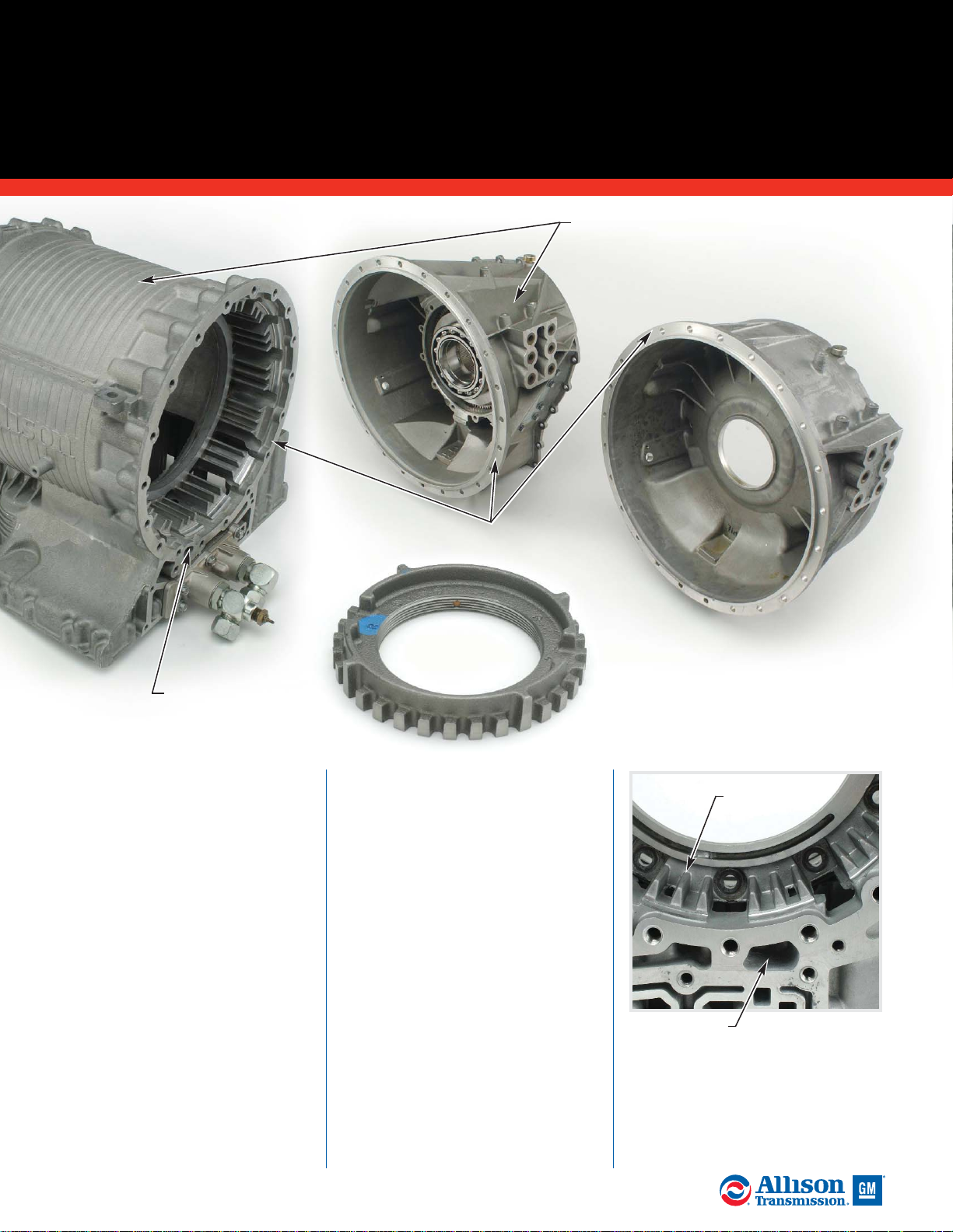
A. Replace housings or other cast
parts that are cracked or broken.
Inspect clutch housing sealing
surfaces for imperfections that
could damage the piston seals or
interfere with mating parts.
Inspect threaded holes for bad
threads. Clean damaged threads
with the correct size tap.
B. Inspect all machined surfaces
for damage that could cause fluid
leakage. Inspect mounting faces
and bores for damage.
C. Inspect all fluid passages for
obstructions, porosity, broken
lands, cracks and land surface
imperfections.
D. Replace housings that have
splines worn beyond wear limits.
Refer to the Wear Limits Table
(7-1) in Service Manual SM2457EN.
NOTE: Some parts have Spiralock®
threaded holes . A standard tap will
eliminate the locking feature
requiring the reworked part to be
replaced. For repair, use a
Spiralock® tap to repair Spiralock®
threaded holes. As of this printing,
the following parts have Spiralock®
threaded holes:
Q
Torque converter front cover
flexplate adapter bolt holes and
lockup clutch backplate bolt
holes.
Q
Output shafts using a single bolt
for flange or yoke retention.
4
2005 General Motors Corporation.
ALLISON TRANSMISSION TECHNICIANS’ GUIDE
ALLISON 4000/B500 PRODUCT FAMILIES
GENERAL INSPECTION GUIDELINES FOR
CAST PARTS & MACHINED SURFACES
C. Fluid
Passages
A. Cast
Part
A. Housings
D. Splines
C. Fluid
Passages
B. Machined
Surfaces
ALLISON 4000/B500 PRODUCT FAMILIES
GENERAL INSPECTION GUIDELINES FOR
GEARS
5
2005 General Motors Corporation.
ALLISON TRANSMISSION TECHNICIANS’ GUIDE
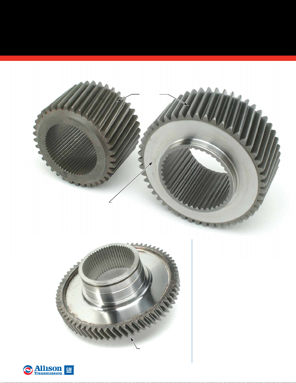
A. Inspect gears for damaged or
broken teeth. Inspect gear teeth for
wear that has changed the original
tooth shape. If this condition is noted,
replace the gear. Inspect gears for load
pattern and signs of distress. Any
signs of distress indicate the gear may
fail during operation. Reusing
distressed gears is an individual
customer decision based on
experience. Backlash cannot be used
to establish critical gear wear. Pits,
scuffs, scores or galling are typically
evident long before backlash exceeds
specification.
B. Inspect the thrust face of gears
for damage. If these defects cannot
be removed with a soft stone, replace
the gear.
Check gears for
damaged or
missing teeth.
A. Gear
Teeth
B. Thrust Face
Surface
A. Gear
Teeth
6
2005 General Motors Corporation.
ALLISON TRANSMISSION TECHNICIANS’ GUIDE
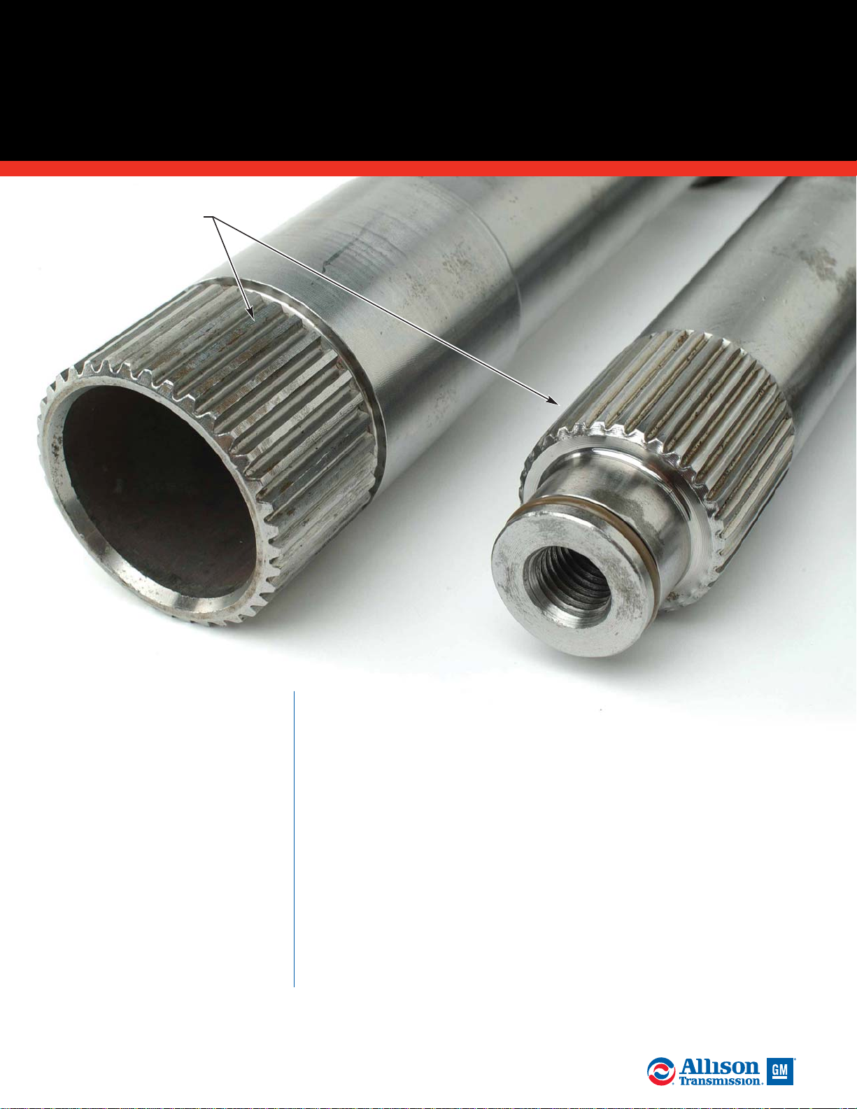
A. Inspect splined parts for
damage. Remove burrs with a soft
stone. Spline wear is not considered
harmful except where it affects the
fit of the splined parts. Spline wear
is determined by comparing feeler
gauge thickness with the thickness
of the worn area on the spline.
Replace parts having excessive
spline wear. The maximum
movement allowed at the splines is
0.38 mm (0.015 inches) if not
otherwise listed in Wear Limits
Table 7-1 in Service Manual
SM2457EN. Do not reuse a splined
part that exceeds the published
maximum spline wear. Backlash
cannot be used to establish critical
spline wear. Accurate backlash
measurement requires the mating
parts to be concentrically located.
ALLISON 4000/B500 PRODUCT FAMILIES
GENERAL INSPECTION GUIDELINES FOR
SPLINES
Inspect splined parts
for burrs, damage
and excessive wear.
A. Splines
7
2005 General Motors Corporation.
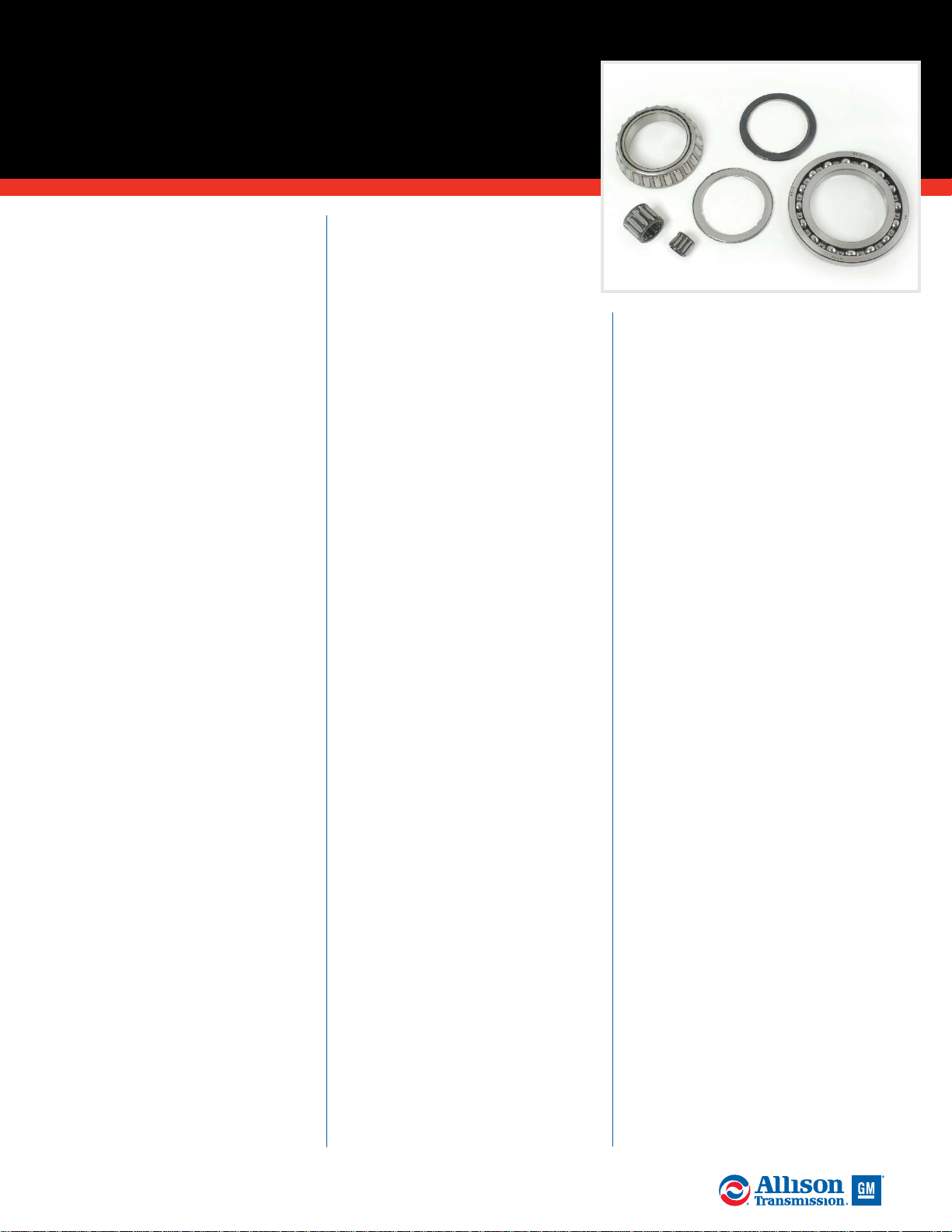
ALLISON TRANSMISSION TECHNICIANS’ GUIDE
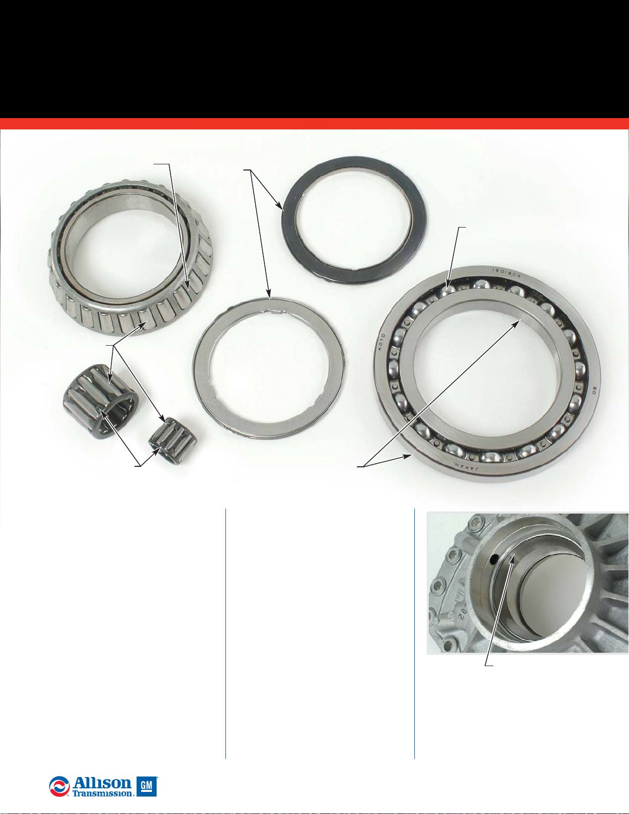
A. Replace the bearing if any
rollers/balls are rusted. Replace the
bearing if balls/rollers have a feeling
of looseness in the retainer or race
compared to a new bearing. Replace
the bearing if balls/rollers are
discolored from heat, lack of
lubrication or debris lapping in the
balls/rollers. Replace the bearing if
the balls/rollers are worn, galled or
abraded. Replace the bearing if it
catches or feels rough after being
thoroughly cleaned.
B. Replace the bearing if any
races are rusted. Replace the
bearing if the bearing balls/rollers
have a feeling of looseness in the
raceway compared to a new
bearing. Replace the bearing if races
are discolored from heat, lack of
lubrication or debris lapping in the
race. Replace the bearing if the
races are worn, galled or abraded.
Replace the bearing if it catches or
feels rough after being thoroughly
cleaned.
C. Replace the bearing if any
retainer or retainer clip is
fractured, bent, dented or missing.
Replace the bearing if any retainer
is rusted. Replace the bearing if
there is a feeling of looseness
between the retainer and ball/roller
compared to a new bearing. Replace
the bearing if it catches or feels
rough after being thoroughly
cleaned.
ALLISON 4000/B500 PRODUCT FAMILIES
GENERAL INSPECTION GUIDELINES FOR
BEARINGS
A. Rollers
B. Bearing
Race
C. Retainer
B. Bearing
Race
B. Bearing Race
(continued)
C. Retainer
C. Retainer
8
2005 General Motors Corporation.
ALLISON TRANSMISSION TECHNICIANS’ GUIDE
General Bearing Handling
& Storage
Dirt is the greatest single enemy
of any antifriction bearing.
Cleanliness - using clean tools in a
clean environment - is at the top
of the list of good service
techniques. Keep bearings sealed in
original containers. Do not allow
anyone to open boxes and handle
bearings. A new bearing, if not
protected, can quickly pick up
enough dust even in an apparently
clean place to seriously affect its life
and operation. Minimize the
possibility of rusting or lubricant
aging in storage by using the oldest
bearings in stock first.
If any part of a bearing assembly
has been compromised, replace all
detail parts in the assembly
(example - races, retainers and the
bearing itself). Most bearings fail
from preventable causes. Follow a
regular system for inspection. Look
for bearings with obvious damage
first.
General Bearing Inspection
Do not try to judge the condition of
a bearing until after cleaning. Do
not spin bearings while cleaning
them. Rotate them slowly while
washing. Do not spin any bearings
with air pressure. Put bearings
under axial pressure while rotating
to bring the balls and races firmly in
contact with each other. For single
row angular contact bearings,
pressure must always be applied on
thrust faces.
When immersing in solvent, place
bearings in a wire basket so there is
plenty of space for cleaner to reach
all parts. Tanks should have a
screened false bottom to prevent
settled debris from being stirred up
into the bearings. Agitate the
basket frequently until grease, oil or
sludge is thoroughly loosened and
can be flushed out. Blow solvent
out of bearings using dry, filtered
air. Be careful not to spin the
bearing using air pressure.
Lubricate bearings immediately
after drying to avoid rust.
NOTE: Wear eye protection and
follow the appropriate safety
guidelines when using solvents to
clean components.
Badly discolored rollers and races
are usually a sign of inadequate
lubrication. Replace badly
discolored bearings. Moderately
discolored rollers, cages and races
do not necessarily mean that the
bearing needs replacement.
Technicians should always try to
determine the root cause of failure
when inspecting failed components.
It’s important the root cause be
identified and repaired to avoid the
same failure in the future. Bearings
should be replaced for the
following reasons:
Rusted rollers, balls or
raceways -
rusted rollers, balls or
raceways are usually caused by
water passing worn or defective
seals, or by condensation inside the
housing.
Fractured races - a fractured race
can be caused by forcing a cocked
bearing on or off a shaft. An
excessively tight press fit can also
cause a race to fracture.
Worn, galled or abraded
surfaces - worn, galled or abraded
surfaces on a bearing may be the
result of a loose fit on a shaft or in a
housing. A locked bearing spinning
on a shaft or in a housing can also
create this type of damage.
General feeling of roughness -
inspect for a general feeling of
roughness which remains
unchanged by thorough cleaning.
This condition generally indicates
damage to raceways or rollers
caused by dirt, pitting, brinelling or
corrosion.
Catchy feeling - inspect for a
catchy feeling at one or more points
which repeated flushing will not
remove. This condition generally
indicates a spalled or fatigued spot
on the race. Thorough flushing is
necessary to be sure the catchy or
rough feeling is not caused by
foreign debris in the bearing.
Excessive looseness - inspect for
excessive looseness which indicates
lapping by dirt or an abrasive
contaminate in the lubricant. If in
doubt, compare the end play
against the end play of an identical
new bearing. The races, balls and
rollers will appear dull gray when
lapped by dirt.
ALLISON 4000/B500 PRODUCT FAMILIES
GENERAL INSPECTION
GUIDELINES FOR BEARINGS
(continued)
9
2005 General Motors Corporation.
ALLISON TRANSMISSION TECHNICIANS’ GUIDE
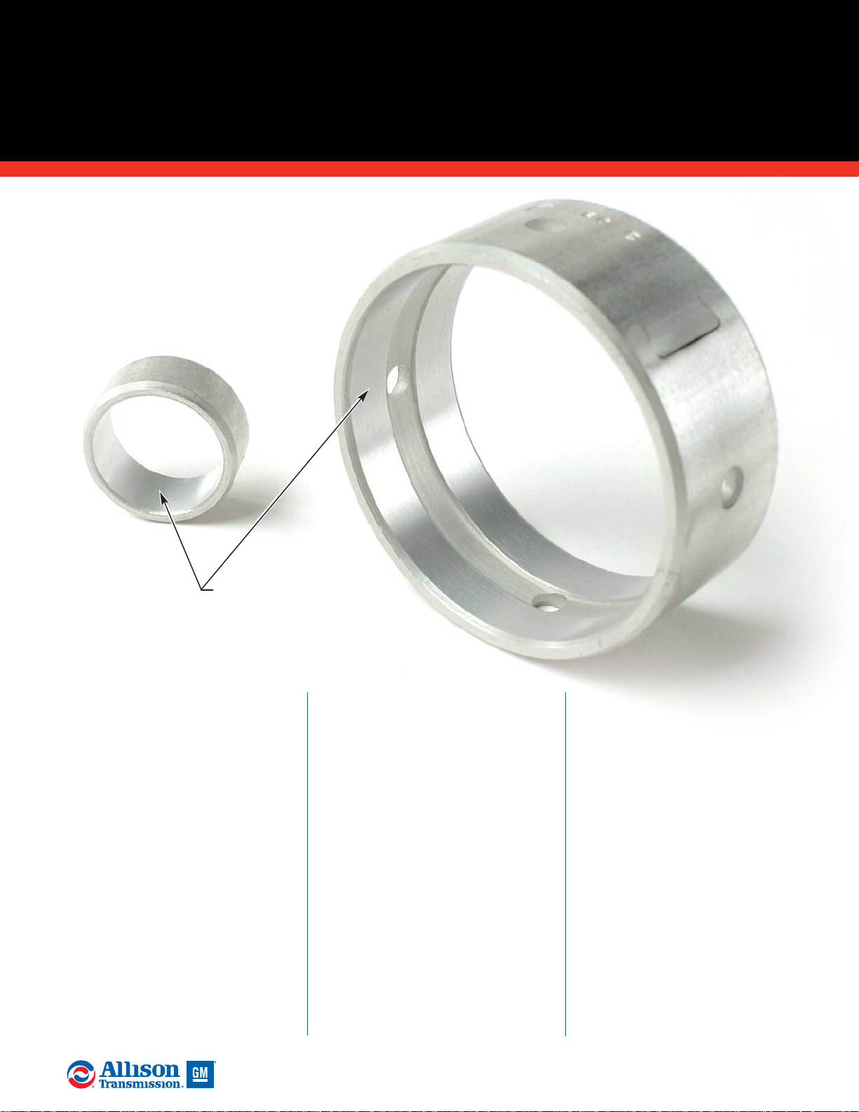
A. Inspect bushings for wear
beyond service limits. Replace any
bushing which is excessively worn.
Inspect bushings for discoloration
and surface damage due to lack of
lubrication. Replace any bushing
which is damaged.
General Bushing Information
Mechanically, bushings are the
simplest type of journal bearing and
are often referred to as “plain”
bearings. A bushing is simply a
sleeve of bearing material, such as
bronze or aluminum, in which a
component rides. Bushing wear is
strongly influenced by the quantity
and condition of the lubricant.
Bushing bearing surfaces are
sometimes grooved to better
distribute lubrication across the
bearing surface.
Some bushings are susceptible to
material leaching. This can be
caused by oxidized oil that has
turned acidic combined with heat
and mechanical loading. The TAN
(Total Acid Number) of the
transmission oil should not change
by more than 3 from the baseline
(new fluid) TAN. Changing
transmission oil per recommended
change intervals or based on a
successful oil sampling program
will help prevent material leaching.
ALLISON 4000/B500 PRODUCT FAMILIES
GENERAL INSPECTION GUIDELINES FOR
BUSHINGS
Bushing wear is strongly
influenced by the
quantity and condition
of the lubricant.
A. Bushing
10
2005 General Motors Corporation.
ALLISON TRANSMISSION TECHNICIANS’ GUIDE
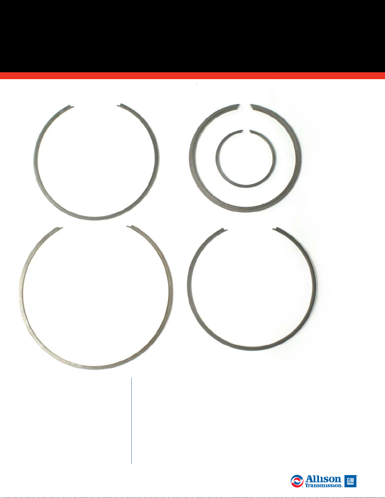
A. Inspect retaining rings for
damage, distortion and excessive
wear. Replace retaining rings if
damage cannot be repaired using a
soft stone or crocus cloth.
ALLISON 4000/B500 PRODUCT FAMILIES
GENERAL INSPECTION GUIDELINES FOR
RETAINING RINGS
Examine retaining
rings for damage,
distortion or
excessive wear.
A. Retaining
Rings
11
2005 General Motors Corporation.
ALLISON TRANSMISSION TECHNICIANS’ GUIDE
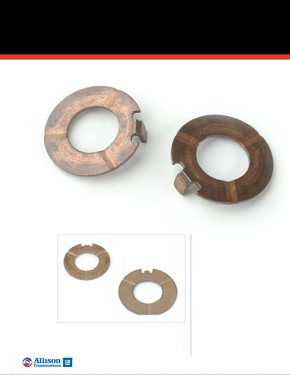
A. Replace thrust washers if they
are worn beyond service limits.
Replace thrust washers if they are
galled, abraded or distorted.
Replace thrust washers if they are
damaged due to a lack of
lubrication.
ALLISON 4000/B500 PRODUCT FAMILIES
GENERAL INSPECTION GUIDELINES FOR
THRUST W ASHERS
A. Thrust
Washers
Thrust
Washers
12
2005 General Motors Corporation.
ALLISON TRANSMISSION TECHNICIANS’ GUIDE
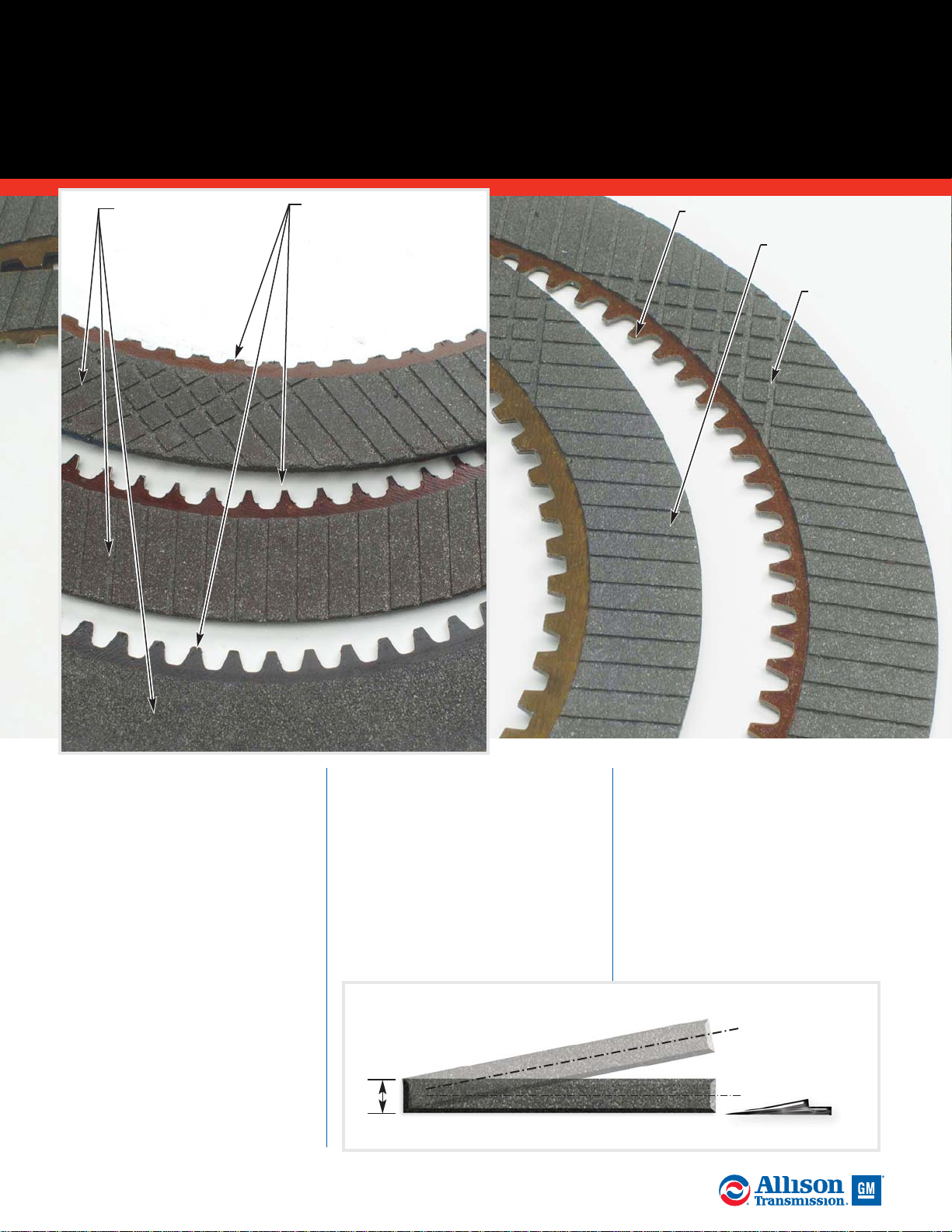
A. Contact
Surface
C. Oil
Groove
Depth
D. Spline
Teeth
A. Inspect friction plate contact
faces and splines for excessive
wear, damage and coning. Inspect
the plates for burrs, pitted faces,
cracks, distortion and damaged
spline teeth.
B. Measure friction plate
thickness and coning. Reference
the Service Manual for minimum
thickness and maximum coning
specifications. Do not reuse friction
plates that do not meet published
specifications. If reused plates are
slightly coned (within
specification), make sure each plate
is stacked with the cone facing the
same direction.
C. Measure friction plate oil
groove depth. Replace any plates
that are not within Service Manual
minimum groove depth
specification.
D. Inspect spline teeth for
excessive wear and battering.
Replace the clutch plate if damage
cannot be repaired using a soft
stone or crocus cloth. Replace the
clutch plate if spline teeth are
broken or missing.
NOTE: Anti-freeze (glycol) and/or
water can adversely affect the
bonding agent between the friction
material and steel core. Replace any
friction plates which have been
exposed to water and/or glycol.
ALLISON 4000/B500 PRODUCT FAMILIES
GENERAL INSPECTION GUIDELINES FOR
CLUTCH PLATES
B. Clutch Plate
Thickness and
Coning
Check Using
Feeler Gauge
Thickness
Coned Plate
Flat Plate
(continued)
Oil grooves
appear shallow
or worn away measure plate
thickness and
groove depth.
Spline teeth battered
and worn - may be an
indication of driveline
issues. Replace
clutch plates and
check driveline.
13
2005 General Motors Corporation.
ALLISON TRANSMISSION TECHNICIANS’ GUIDE
NOTE: The current clutch friction plates
were implemented April of 2000 starting
with s/n 6610062126. Current clutch
friction plates will have two or more
missing splines. Former friction plates
will either have one spline missing or
none missing. Any 4000/B 500 model
transmission may be updated from former
C5 friction plates to current C5 frictions
without recalibrating the transmission
ECU. The rest of the clutches in the main
housing (C1 through C4) must be
updated with current friction plates if
any other individual clutch besides C5 is
updated from former to current friction
plates. Any update from former frictions
to current frictions in C1 through C4 for
a 4000 Series or B500 with a WTEC II
ECU will require a new ECU calibration
from Allison Transmission. Any update
from former frictions to current frictions
in C1 through C4 for a 4000 Series or
B500 with a WTEC III ECU with a
calibration prior to October 25, 1999 will
require an updated ECU calibration from
Allison Transmission. Do not intermix
both former and current friction plates in
a clutch pack.
The P3 ring gear changed to a harder ring
gear on s/n 6610027070. The current P3
ring gear identifier is a groove machined
around the outer diameter of the gear.
The P3 ring gear with a groove identifier
requires the C5 friction with two missing
splines if updating from former C5
frictions. If any 4000/B500 series model
without the harder ring gear (no groove
on O.D.) is being updated with current
C5 frictions, then it will require the C5
friction that has three missing internal
splines. The C5 friction plate missing
three splines will exhibit spline wear if
used with the current P3 ring gear with a
groove identifier on the O.D. The former
P3 ring gear (no groove on O.D.) will
exhibit premature wear if used with the
current C5 friction with two missing
internal splines. No ECU calibration is
necessary for updating C5 clutch plates.
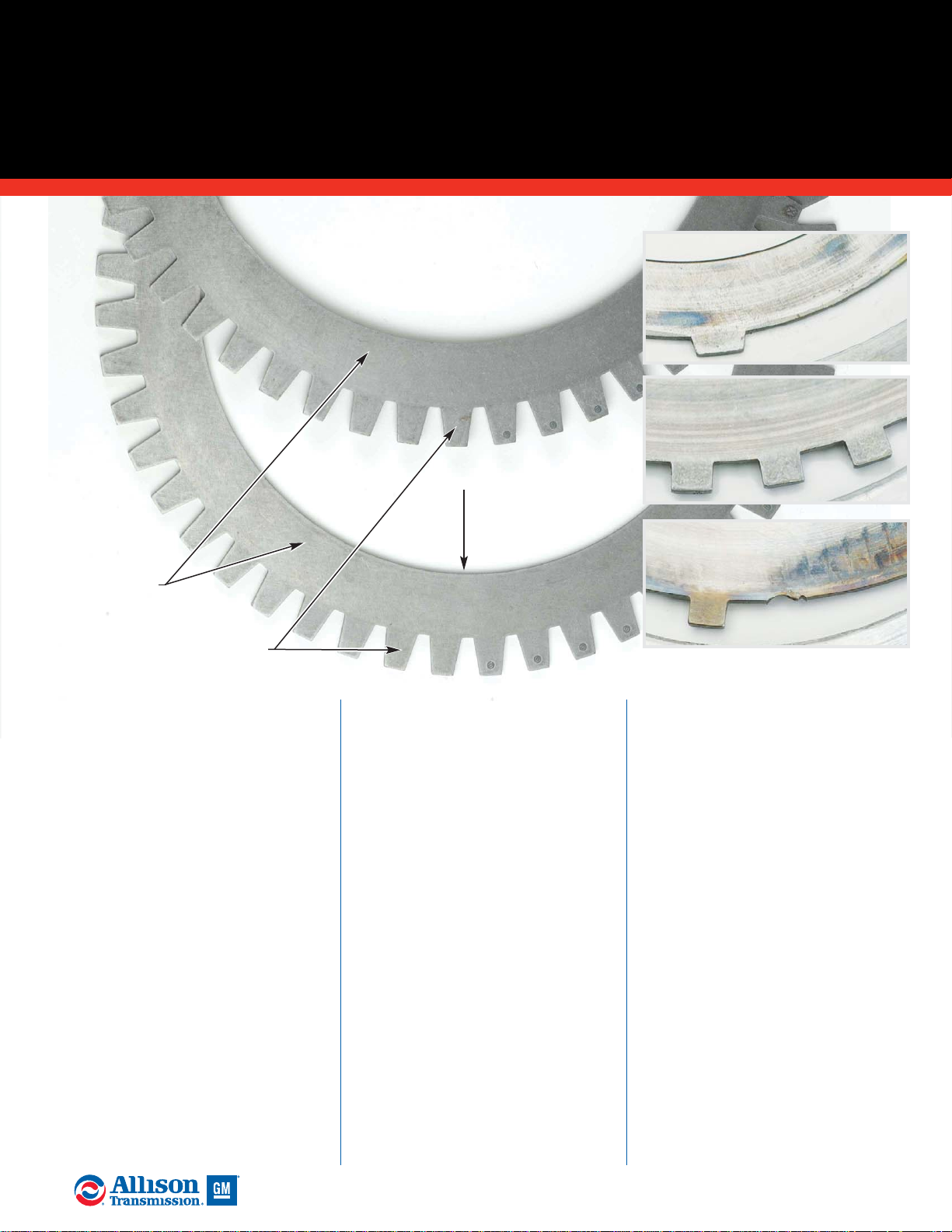
A. Inspect reaction plates for
excessive wear, warping, coning
and surface damage. Replace any
plate with wear exceeding service
limits or with damage which
cannot be repaired using a soft
stone or crocus cloth..
B. Measure reaction plate
thickness and coning. Reference
the Service Manuals for minimum
thickness and maximum coning
specifications. Do not reuse plates
that do not meet published
specifications. If reused plates are
slightly coned (within
specification), make sure each plate
is stacked with the cone facing the
same direction.
C. Inspect reaction plate tangs
for damage. Replace the plate if
damage cannot be repaired using a
soft stone or crocus cloth.
ALLISON 4000/B500 PRODUCT FAMILIES
GENERAL INSPECTION GUIDELINES FOR
(continued)
CLUTCH PLATES
A. Contact
Surfaces
B. Thickness
& Coning
(see prior
page graphic)
C. Tangs
Acceptable
discoloration reuse plates.
Excessive scoring replace plates.
Broken tangs replace plates.
14
2005 General Motors Corporation.
ALLISON TRANSMISSION TECHNICIANS’ GUIDE
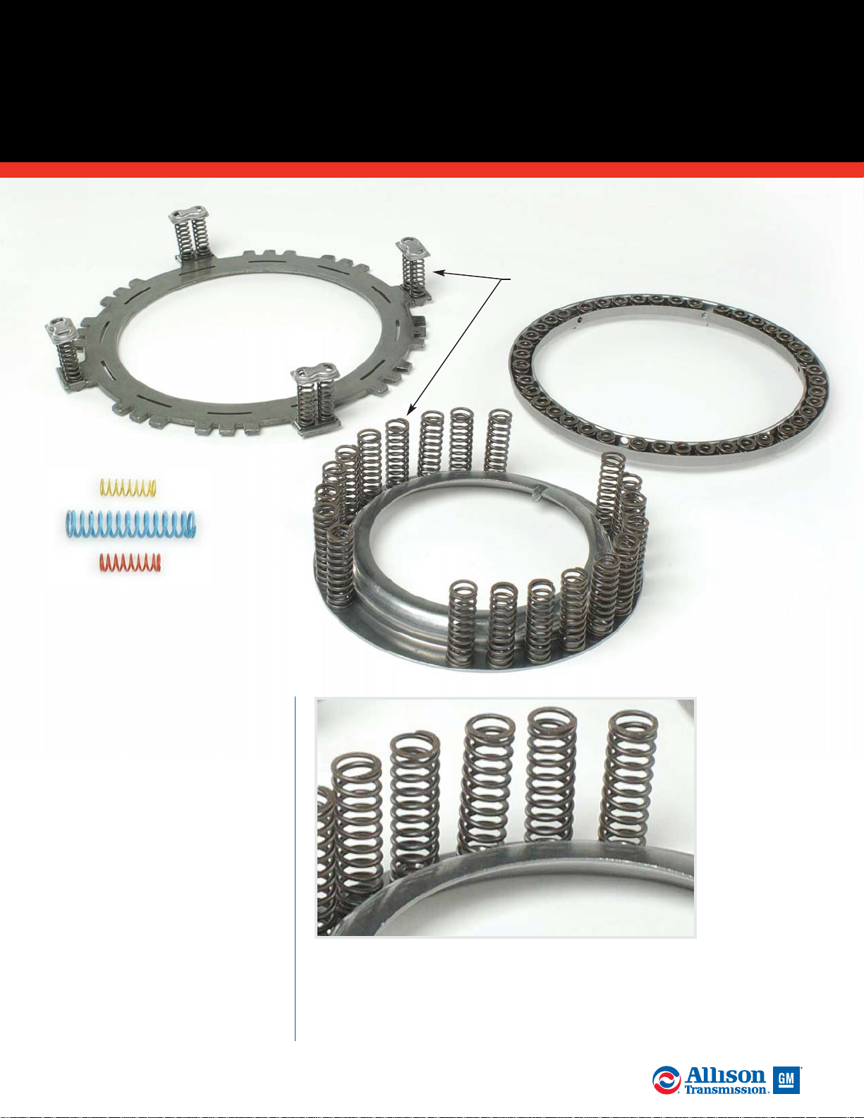
A. Inspect springs for permanent
set and wear due to rubbing
adjacent parts. Replace the spring if
any of these defects are identified or
if the spring fails to meet published
service limits. Reference the Spring
Data Charts in Service Manual
SM2457EN for spring identification
and service limit specifications.
ALLISON 4000/B500 PRODUCT FAMILIES
GENERAL INSPECTION GUIDELINES FOR
SPRINGS
Inspect springs for signs of
overheating, permanent set
or wear due to rubbing
adjacent parts.
A. Springs
Reference the Service Manual
Spring Data Charts for spring
identification and specifications.
15
2005 General Motors Corporation.
ALLISON TRANSMISSION TECHNICIANS’ GUIDE
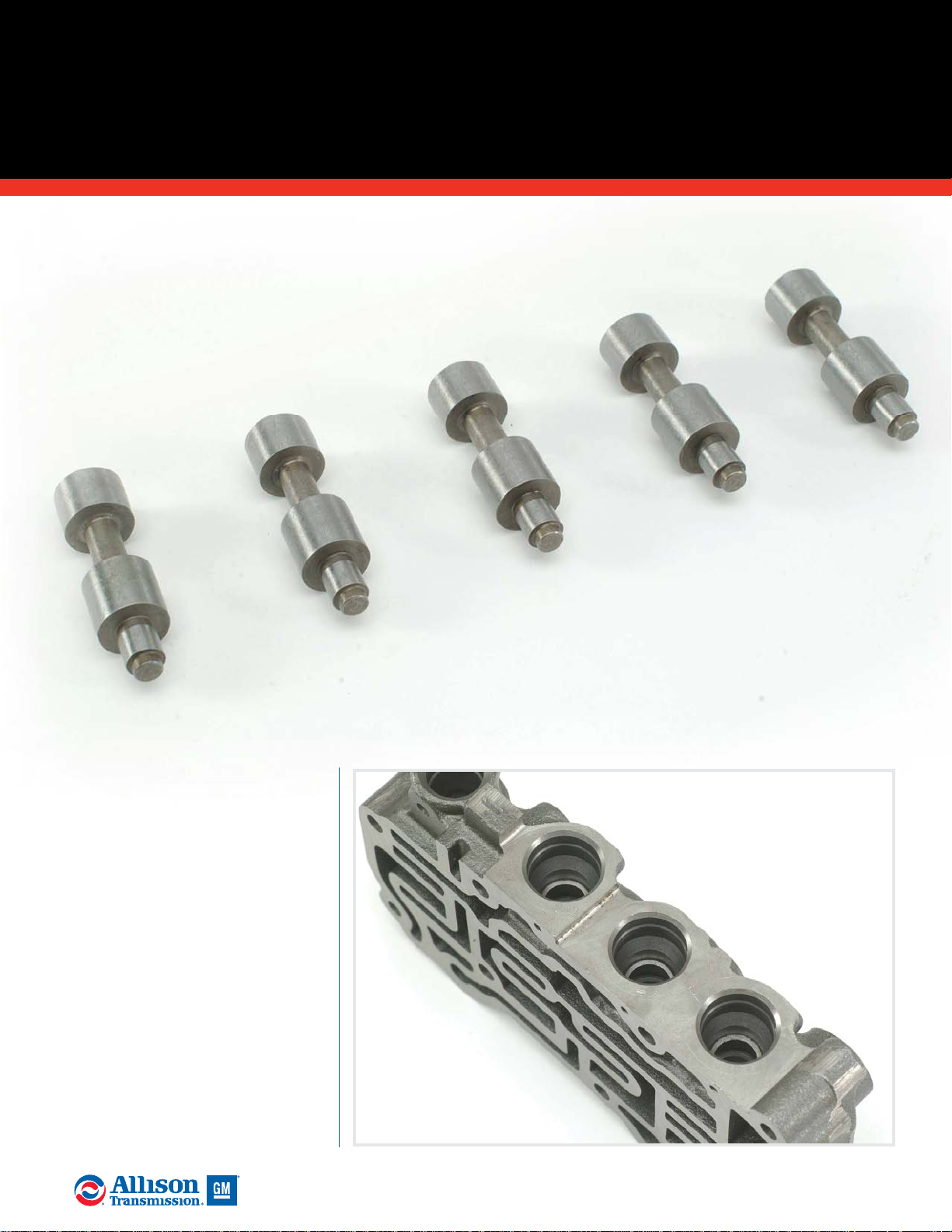
A. Valves must be free of nicks,
burrs and scoring and operate
smoothly in their bores without
sticking. Dry valves must move
freely in their bores by their own
weight. Replace damaged valves. A
soft stone or crocus cloth can be
used in an attempt to repair slight
irregularities.
B. Valve bores must be free of
nicks, burrs and scoring. No honing
of any kind is allowed. A soft stone
or crocus cloth can be used in an
attempt to repair slight
irregularities.
ALLISON 4000/B500 PRODUCT FAMILIES
GENERAL INSPECTION GUIDELINES FOR
VALVES & VALVE BORES
Valves should move freely in
their bores, when dry, under
their own weight.
Valve bores must
be free of nicks,
burrs and scoring.
A. Valves
B. Valve
Bores
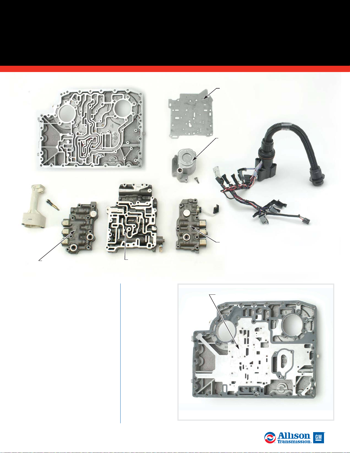
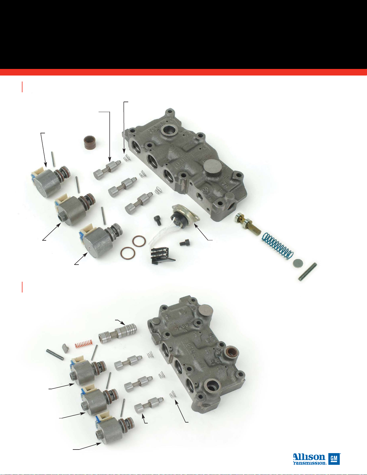
A. Inspect the channel plate for
damage. All passages must be clear
of debris. Inspect all machined
surfaces for burrs, nicks or scoring.
Light stoning and crocus cloth may
be used to eliminate minor high
spots. If a channel plate cannot be
repaired so that all machined
surfaces can seal correctly to their
mating parts, or if thread damage
cannot be repaired, replace the
channel plate.
NOTE: Do not use impact guns (air
wrenches, electric impact
wrenches, etc.) when working with
aluminum threads or when torque
sequencing bolts.
B. Inspect both
separator
plates for dents,
nicks, burrs and
other damage or
distortion.
Replace the
plate if it has
damage which
cannot be
repaired using a
soft stone or
crocus cloth. All
passages must
be clean and
debris free.
A. Channel
Plate
B. Solenoid
Separator Plate
D. Internal
Wiring
Harness
C. Suction
Filter
Assembly
E. Rotating
Clutch Body
Assembly
F. Main Valve
Body Assembly
G. Stationary Clutch
Valve Body Assembly
H. Oil Level
Sensor
ALLISON 4000/B500 PRODUCT FAMILIES
CONTROL MODULE
16
2005 General Motors Corporation.
ALLISON TRANSMISSION TECHNICIANS’ GUIDE
B. Separator Plate
Separator plate and gasket installed
on channel plate.
(continued)
ALLISON 4000/B500 PRODUCT FAMILIES
(continued)
CONTROL MODULE
17
2005 General Motors Corporation.
ALLISON TRANSMISSION TECHNICIANS’ GUIDE
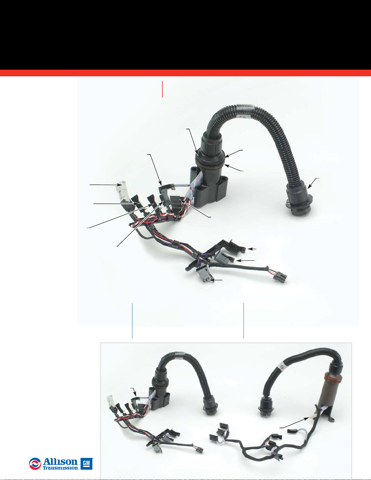
C. Replace the suction filter
assembly during overhaul.
D. Replace or repair the control
module wiring harness if the
wires, terminals or
connectors are visibly
damaged. Inspect the
molded harness channel
for cracks or breaks.
Replace the harness if
the molded channel is
damaged. Check sump
temperature resistance
following the guidelines
and specifications listed
in the Service Manual
and Troubleshooting
Manual.
NOTE: Transmissions built prior to
S/N 6610014067 used the former
design sump temperature sensor.
Sensor resistance specifications
differ between the former and
current designs. Be sure to use the
correct resistance specification
chart for the sensor being checked.
Sump Temperature
Sensor (TID 2, 3)
D Solenoid (C4)
C Solenoid (C3)
E Solenoid
(C5)
F Solenoid
(Lockup)
Oil Level
Sensor
Feed
Through
Stand-Off
C3 Pressure
Switch
A Solenoid
(C1)
Feed
Through
Harness
B Solenoid
(C2)
G Solenoid
(C2 Latch)
Identification Detail:
Internal Wiring Harness
Current TID2/TID3
Harness
Former TID1
Harness
TID1 Sump
Temp. Sensor
(continued)
Dust
Seal
O-Ring
Seal
TID 2, 3
Sump Temp.
Sensor
ALLISON 4000/B500 PRODUCT FAMILIES
CONTROL MODULE
(continued)
18
2005 General Motors Corporation.
ALLISON TRANSMISSION TECHNICIANS’ GUIDE
E, F, G. Valves, valve body bores
and oil passages must be free of
debris, nicks, burrs, scoring and
galling. Valves should move freely
in their bores, when dry, under
their own weight. Repair or replace
valves and/or valve bodies failing to
meet these requirements.
Valve body machined surfaces
must be free of debris, nicks, burrs
and scoring. Light stoning of these
machined surfaces is permitted to
correct minor defects. Replace any
valve body that cannot be repaired.
Inspect all threaded holes for
damage and debris. Replace the
valve body if the thread damage
cannot be repaired.
NOTE: Do not use impact guns (air
wrenches, electric impact
wrenches, etc.) when working with
aluminum threads or when torque
sequencing bolts.
Replace valve springs which are
broken, permanently set or worn
due to rubbing adjacent parts.
Reference the Spring Data Charts in
the Service Manual for spring
specifications and identification.
Valve stops and retention pins
must not be damaged or battered.
Replace valve stops or pins which
have damage that cannot be
removed using a soft stone or
crocus cloth.
Replace solenoids if they are visibly
damaged. Proper solenoid
resistance is 3 to 4 ohms measured
between the two solenoid
terminals. Check resistance
between each solenoid terminal and
the solenoid body. Replace the
solenoid if resistance measures less
than 100k ohms.
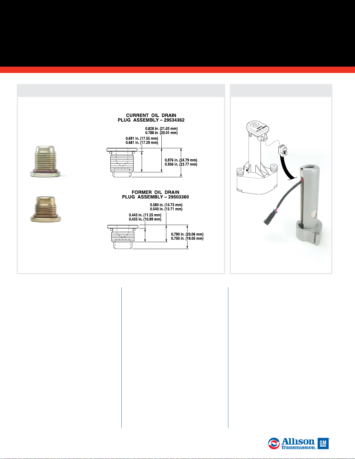
Supersession Information
Oil Drain Plug Redesign SIL 5-WT-98, Rev. A
Current plug is
backward compatible
with all control
modules.
Supersession Information
Oil Level Sensor Redesign SIL 19-WT-99
Kit must be used when
replacing former sensor
with current sensor.
Current
Former
(continued)
Replace the C3 pressure switch if
it is visibly damaged. Resistance
between the two switch terminals
should measure 20k ohms or higher
when the switch is open (and no
pressure is present). Resistance
between the two terminals should
not exceed 2 ohms when the switch
is closed (159 kPa-255 kPa or 23-37
psi present).
H. Replace the optional oil level
sensor if it is determined it is not
functioning correctly.
ALLISON 4000/B500 PRODUCT FAMILIES
(continued)
CONTROL MODULE
19
2005 General Motors Corporation.
ALLISON TRANSMISSION TECHNICIANS’ GUIDE
4” Channel
Plate
2” Channel
Plate
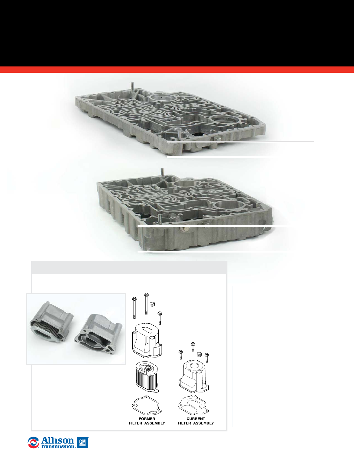
Supersession Information
Suction Filter Redesign - SIL 1-WT-00
Replace the
assembly
during
overhaul.
Current
Former
(continued)
ALLISON 4000/B500 PRODUCT FAMILIES
CONTROL MODULE
(continued)
B Solenoid
(C2)
F Solenoid
(Lockup)
A Solenoid
(C1)
Rotating
Clutch V alve
Body
Solenoid
Regulator
Valves
C3
Pressure
Switch
Solenoid
Regulator
Springs
Identification Detail: Rotating Clutch Valve Body Assembly
D Solenoid
(C4)
C Solenoid
(C3)
E Solenoid
(C5)
Solenoid
Regulator
Valves
Solenoid
Regulator
Springs
Stationary
Valve Body
Overdrive Knock
Down V alve
Identification Detail: Stationar y Clutch Valve Body Assembly
20
2005 General Motors Corporation.
ALLISON TRANSMISSION TECHNICIANS’ GUIDE
Accumulator
Relay V alve
(continued)
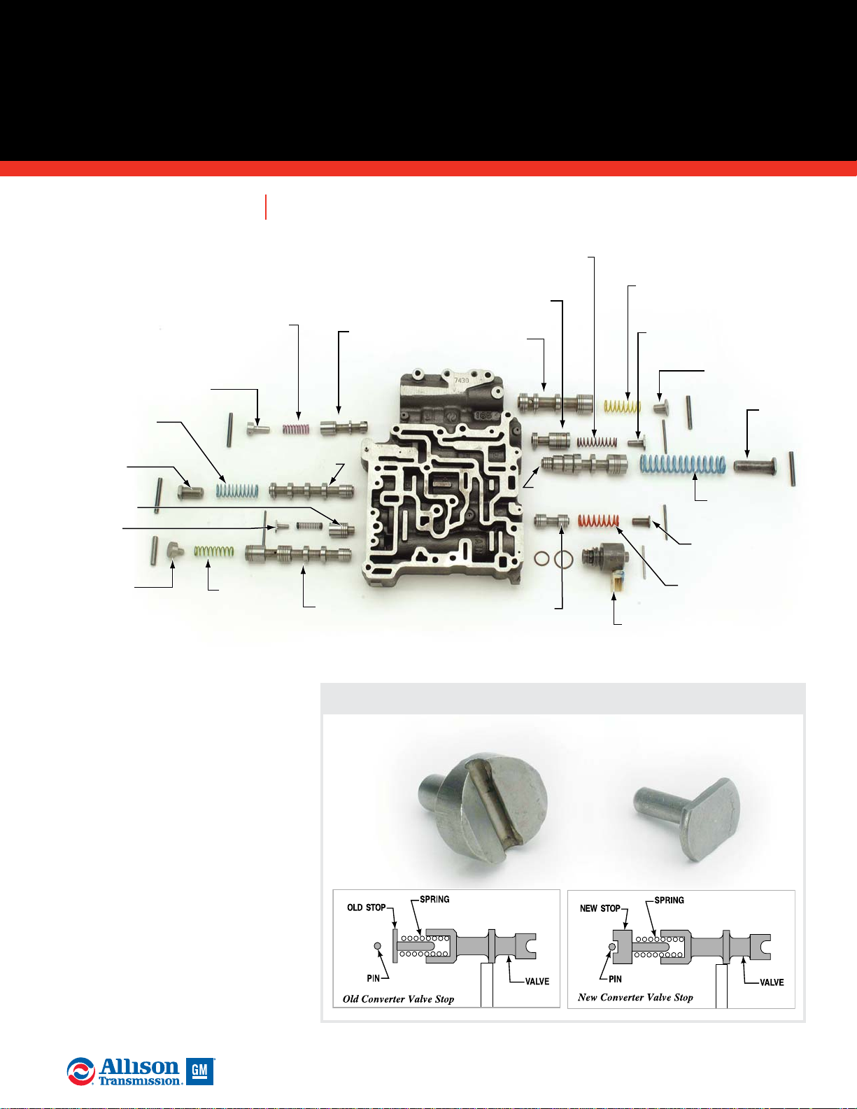
ALLISON 4000/B500 PRODUCT FAMILIES
(continued)
CONTROL MODULE
Converter
Regulator
Valve
Converter
Regulator
Spring
Converter
Regulator
Valve Stop
Main
Regulator
Valve Stop
Control
Main Valve
Control Main
Valve Spring
Control Main
Valve Stop
Main Regulator
Valve Spring
Lube Regulator
Valve
Lube Regulator
Valve Spring
Lube Regulator
Valve Stop
Main Regulator Valve
Lockup
Valve
Lockup
Valve Spring
Lockup
Valve Stop
C1 Latch Valve
C2 Latch
Valve
Main Valve
Body
G Solenoid
C1 Latch
Valve Spring
C2 Latch
Valve
Spring
C1 Latch
Valve Stop
C2 Latch
Valve Stop
Exhaust
Backfill
Valve Stop
Exhaust
Backfill V alve
Supersession Information
Converter Regulator Valve Stop Redesign SIL 12-WT-99
21
2005 General Motors Corporation.
ALLISON TRANSMISSION TECHNICIANS’ GUIDE
Identification Detail: Main Valve Body Assembly
Current
Stop
Former
Stop
(continued)
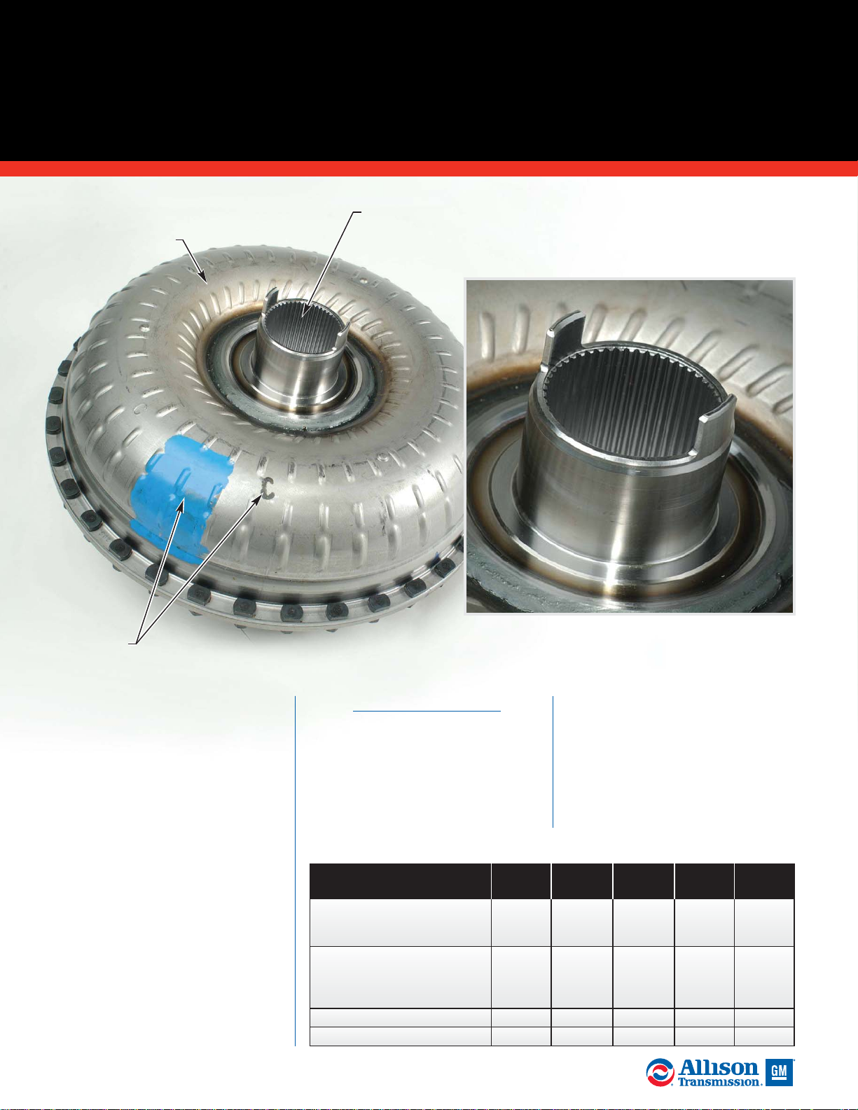
A. Converter
Pump Exterior
A.
Inspect the converter pump
exterior for dents and sealing
surface damage. Replace the
converter pump if damage cannot
be remove with a soft stone or
crocus cloth.
B. Inspect the converter pump
hub for damage and excessive wear.
Minimum pump hub diameter is
88.99 mm (3.504 inch). Inspect the
pump hub tangs for cracks, impact
damage or broken tangs. Maximum
allowable tang step wear is 0.31 mm
(0.012 inch). On PTO-equipped
models, check the splines inside
the hub for wear and damage.
Maximum spline wear is 0.38 mm
(0.015 inch).
NOTE: Do not use crocus cloth on
the converter pump hub. Polishing
the hub with crocus cloth can cause
improper input seal performance
resulting in fluid leakage.
NOTE: Pump hub tang breakage or
deformity accompanied by charging
pump bushing failure and ground
sleeve wear is often caused by poor
transmission fluid condition due to
improper maintenance intervals.
Observation of proper fluid change
intervals is key to optimum
transmission life.
Inspect the pump hub tangs for cracks,
impact damage and broken tangs.
B. Drive Hub
B. Drive
Hub
Model
Identifiers
(see chart)
Torque Converter Model
Designation
Front Cover Sticker and
Converter Paint Dot Color
(Exterior Marker)
Engraved Letter Identifiers
(Torus Ring of Converter
Pump) Ink Stamped Letter
(Exterior of Converter Pump)
Number of Stator Blades
Paint Dot Color on Stator
TC-521
Green
E
19
None
TC-531
Pink
D
19
None
TC-541
Blue
C
19
None
TC-551
Orange
B
19
None
TC-561
Yellow
A
19
None
4000 Product Family Torque Converter Identification Chart
(continued)
ALLISON 4000/B500 PRODUCT FAMILIES
TORQUE CONVERTER MODULE
22
2005 General Motors Corporation.
ALLISON TRANSMISSION TECHNICIANS’ GUIDE
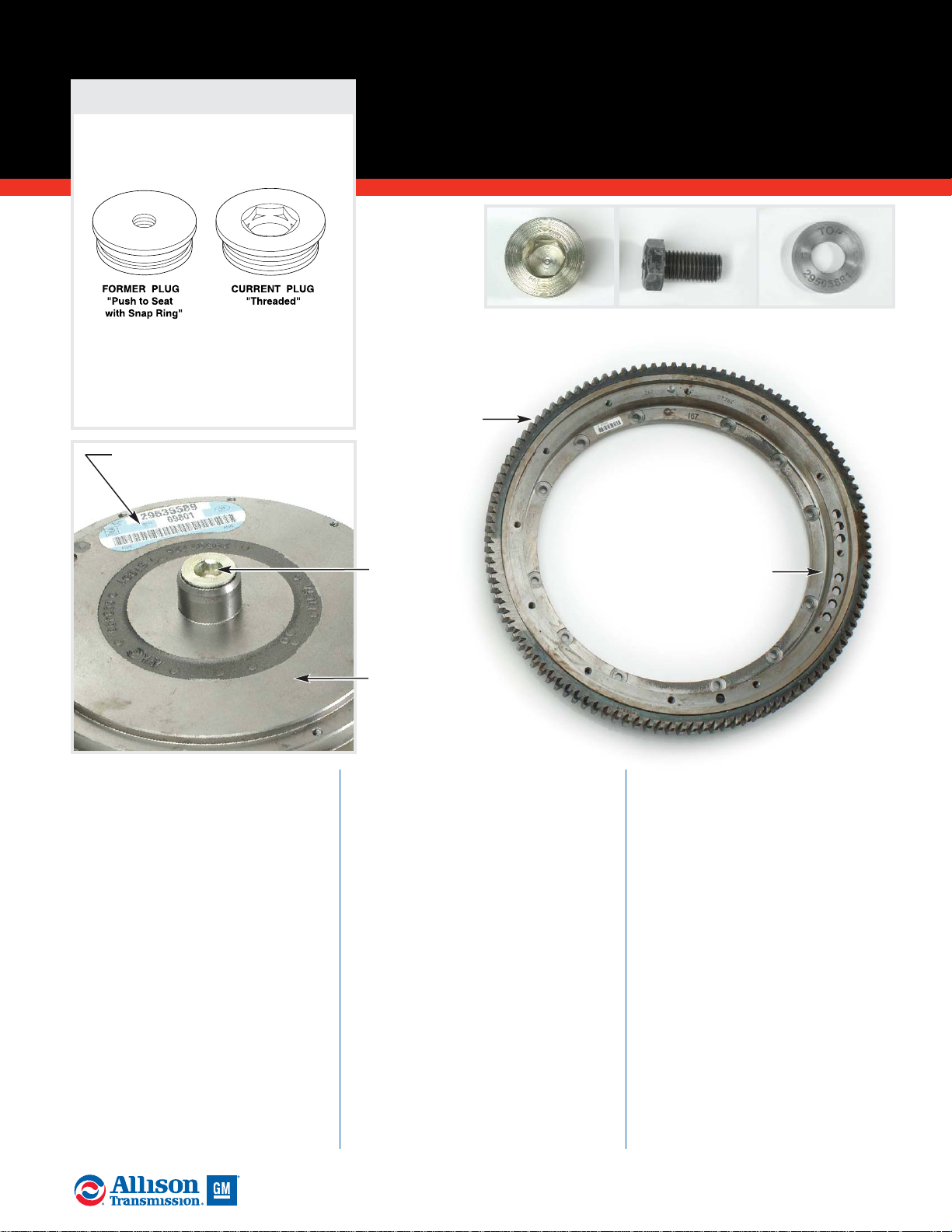
C. Inspect the torque converter
front cover mounting faces for
damage. Inspect the flexplate
adapter bolt holes for stripped or
damaged threads.
D. Inspect the front cover pilot
for damage and wear. Maximum
pilot diameter is 61.77 mm (2.432
inches). Inspect the torque
converter end plug and the
retaining bolt for stripped or
damaged threads. Verify that the
correct turbine shaft selective shim
is installed following the Service
Manual procedures.
E. Inspect the engine starter ring
gear for chipped, worn or broken
teeth.
F. Inspect the flexplate adapter
mounting faces for surface damage.
Replace the adapter if damage
cannot be repaired using a soft
stone or crocus cloth. Inspect the
flexplate adapter bolt holes fro
stripped or damaged threads. Clean
damaged threads using the correct
size tap. Replace the adapter if
damage cannot be repaired.
NOTE: The flexplate adapter bolt
holes use Spiralock® threads. A
Spiralock® tap must be used when
repairing damaged threads. Using a
standard tap will destroy the
locking feature. If this occurs, the
torque converter front cover must
be replaced.
ALLISON 4000/B500 PRODUCT FAMILIES
TORQUE CONVERTER MODULE
(continued)
23
2005 General Motors Corporation.
ALLISON TRANSMISSION TECHNICIANS’ GUIDE
C. Front
Cover
Mounting
Face
Current
Plug
E. Ring
Gear
D. Pilot
F. Flexplate
Adapter
Converter
Retaining Bolt
Turbine Shaft
Selective Shim
Supersession Information
Converter Plug and Front
Cover Update SIL-21-WT-98
Model Identifiers (see
chart previous page)
The current front cover has a
threaded pilot to accept the
current converter plug. Plugs
are not interchangeable
(continued)

A. Inspect the converter pump
interior. Replace the assembly if
the vanes are damaged, cracked or
loose.
B. Replace the converter pump
assembly if the torus ring is loose
or cracked.
C. Inspect the seal surface
between the converter pump
assembly and the front cover.
Light stoning is permitted to
remove slight irregularities.
ALLISON 4000/B500 PRODUCT FAMILIES
TORQUE CONVERTER MODULE
(continued)
24
2005 General Motors Corporation.
ALLISON TRANSMISSION TECHNICIANS’ GUIDE
A. Converter
Pump Interior
Vanes
B. Torus
Ring
Replace the assembly if the vanes are
damaged, cracked or loose.
C. Seal Ring
Area
C. Front Cover-to-
Converter Pump
Sealing Surface
(continued)

A. Converter
Turbine
Blades
B. Torus
Ring
C. Rivets
D. Turbine Hub
E. Splines
Turbine
Assembly
Exterior
Turbine
Assembly
Interior
A. Inspect the converter turbine
assembly. Replace the assembly if
the blades are cracked, broken or
loose.
B. Inspect the torus ring. Replace
the turbine assembly if the torus
ring is loose or cracked.
C. Inspect the rivets. Replace the
turbine assembly if the rivets are
loose or cracked.
D. Inspect the converter turbine
hub. Replace the converter turbine
assembly if the hub is worn beyond
limits. Minimum allowable hub
diameter is 66.69 mm (2.626
inches). Inspect the sealring groove
for damage.
E. Inspect the hub splines for
damage and wear. Spline movment
between the lockup damper and
turbine hub cannot exceed 0.38
mm (0.015 inch). Replace the
turbine assembly if splines are
excessively worn.
F. Inspect the thrust bearing
following the “General Inspection
Guidelines for Bearings” section of
this manual. Replace any thrust
bearing failing these inspection
procedures.
ALLISON 4000/B500 PRODUCT FAMILIES
TORQUE CONVERTER MODULE
(continued)
25
2005 General Motors Corporation.
ALLISON TRANSMISSION TECHNICIANS’ GUIDE
Inspect the hub splines and rivets for damage and wear.
Turbine hub
sealring groove Sealring installed.
F. Thrust
Bearing
(continued)

A. Torque converter lockup
clutch components fit inside the
front cover. Install a new turbine
sealring in the converter cover bore
then measure the sealring inside
diameter. Replace the cover
assembly if diameter exceeds 61.77
mm (2.432 inch).
B. Inspect the converter cover
bushing for damage. Replace the
bushing if damage cannot be
removed with crocus cloth.
Maximum allowable bushing inside
diameter is 66.91 mm (2.634 inch).
C. Inspect the lockup clutch
piston for damage. Minimum
allowable piston thickness is 6.53
mm (0.257 inch).
D. Inspect the lockup clutch
backplate for damage, scoring and
overheating. Minimum allowable
plate thickness is 11.79 mm
(0.464 inch).
NOTE: If the backplate is within
thickness limits but has surface
damage due to metal transfer
between the backplate and lockup
damper, the plate may be reused by
turning it over so that the lockup
damper has a new contact surface.
E. Replace the lockup clutch
damper if the friction surfaces are
worn beyond service limits.
Minimum allowable friction surface
thickness is 8.51 mm (0.335 inch).
Maximum allowable damper
distortion is 0.51 mm (0.020 inch).
Maximum allowable movement
between the damper and converter
turbine splines is 0.38 mm (0.015
inch). Replace the damper if any of
these measurements are beyond
allowable limits.
F. Inspect thrust bearing
following the “General Inspection
Guidelines for Bearings” section of
this manual. Replace any thrust
bearing failing these inspection
procedures.
ALLISON 4000/B500 PRODUCT FAMILIES
TORQUE CONVERTER MODULE
(continued)
26
2005 General Motors Corporation.
ALLISON TRANSMISSION TECHNICIANS’ GUIDE
A. Sealring
Bore
D. Backplate
B. Bushing
E. Lockup
Damper
Front
Cover
Supersession Information
Lockup Clutch Damper Assembly
Update SIL-4-WT-00, Rev. B
Current damper is backward
compatible with all torque
converter assemblies. ECU
recalibration is not necessary.
C. Lockup
Clutch
Piston
F. Thrust
Bearing
(continued)

L. Retaining
Ring
D. Star
Plate
A. Stator
Race
F. Thrust
Bearing
E. Front Stator
Thrust Washer
G. Stator
Thrust Plate
B. Stator
Spring
C. Stator
Roller
A. Inspect the stator race for
damage. Replace the race if damage
cannot be repaired using a soft stone
or crocus cloth.
B. Inspect the stator springs for
correct spring height following per
the Service Manual. Replace any
spring which has a free length below
17.8 mm (0.700 inch).
C. Inspect the stator rollers for
damage. Rollers should be smooth,
round and defect-free. Replace
damage or worn rollers.
D. Inspect the star plate for
excessive wear. Replace the star
plate if damage cannot be repaired
using a soft stone or crocus cloth.
E. Inspect the front stator thrust
washer for wear beyond service
limits. Replace the stator thrust
washer it is worn 0.40 mm (0.010
inch) or more. If it is within service
limits, the thrust washer can be
turned over and the un-worn surface
can be used.
F. Inspect the thrust bearings
following the “General Inspection
Guidelines for Bearings” section of
this manual. Replace any thrust
bearings failing these inspection
procedures.
G. Inspect the stator thrust plate
for damage and wear. Replace the
plate if damage cannot be removed
using a soft stone or crocus cloth.
Minimum allowable plate thickness
is 9.45 mm (0.372 inch).
H. Inspect the stator and cam
assembly for damage. Replace the
stator and cam assembly if damaged.
NOTE: Use care when cleaning the
stator and cam assembly. Hot tank
temperatures may be high enough to
release the cam assembly from the
stator.
I. Inspect the stator roller
pockets for wear and damage. Verify
correct spring-to-roller orientation.
Inspect the bottom of the cam
pocket for wear. Replace the stator
and cam assembly if it is worn 0.40
mm (0.010 inch) or more in the
bottom of the pocket.
J. Inspect tanged thrust bearing
race for damage. Replace any
damaged race.
K. Inspect shim for damage.
Replace any damaged shims. Use
procedure for shim selection in 4000
Series Service Manual.
L. Inspect the retaining ring for
damage and distortion. Replace any
distorted or damaged retaining rings.
ALLISON 4000/B500 PRODUCT FAMILIES
(continued)
TORQUE CONVERTER MODULE
27
2005 General Motors Corporation.
ALLISON TRANSMISSION TECHNICIANS’ GUIDE
H. Stator Cam
and Assembly
K. Shim
J. Tanged Thrust
Bearing Race
I. Roller
Stator
Pockets

A. Inspect for torque converter
housing damage. High spots may be
removed with crocus cloth or a soft
stone. Inspect threaded holes for
debris and thread damage. Replace
the torque converter housing if it is
cracked, if it leaks from a damaged
machined surface, or if it has thread
damage which cannot be repaired.
B. Inspect the breather for
damage and obstructions. Replace
the breather if it is damaged. Clean
the breather if it is blocked with
debris.
C. Replace the input speed sensor
if the sensor body or electrical
terminals are damaged. Speed
sensor resistance is 300 ohms (plus
or minus 30 ohms). Replace the
speed sensor if it does not meet the
service limit.
D. On PTO-equipped models,
inspect the converter housing
bearing bore for wear. Maximum
allowable bearing bore inside
diameter is 180.05 mm (7.088
inches). Replace the housing if
damage cannot be repaired using a
soft stone or crocus cloth.
E. Inspect the PTO bearing
retainer mounting face surface
and threads for damage. Replace
the housing if surface damage
cannot be repaired using a soft
stone or crocus cloth. Replace the
housing if thread damage cannot be
repaired.
ALLISON 4000/B500 PRODUCT FAMILIES
TORQUE CONVERTER HOUSING MODULE
28
2005 General Motors Corporation.
ALLISON TRANSMISSION TECHNICIANS’ GUIDE
D. Bearing
Bore
E. Retainer
Mounting
Surface
C. Speed
Sensor &
Bore
B. Breather
B. Breather
A. Torque
Converter
Housing (PTO)
A. Torque
Converter
Housing
(Non-PTO)
F. PTO Drive
Assembly
Bearing
Retainer
H. Oil
Pump
Drive
Hub
M.PTO Drive
Gear Bearings
I. PTO Gear
Teeth
J. Bearing
Surfaces
L. Splines
F. On PTO-equipped models,
inspect the PTO drive bearing
retainer housing bore for damage.
Replace the retainer if damage
cannot be repaired using a soft
stone or crocus cloth. Replace the
retainer housing if the bushing has
spun in the bushing bore.
G. Inspect the retainer housing
bushing for damage and wear.
Replace the bushing if damaged.
Maximum allowable bushing inside
diameter is 89.19 mm (3.511 inches).
Replace the bushing if it is worn
beyond service limits.
H. Inspect the oil
pump drive hub.
Replace the drive hub
if damage cannot be
repaired using a soft
stone or crocus cloth.
I. Inspect the PTO drive gear
teeth for chips, pitting and
excessive wear. Replace the gear if
damage cannot be repaired using a
soft stone or crocus cloth.
NOTE: Some axial movement of the
gear is normal, but movement
should not exceed 3.175 mm (0.125
inch). Replace the PTO bearings if
axial movement exceeds service
limit.
NOTE: Normal operating backlash
after PTO is installed is 0.1 mm to
0.66 mm (0.004 to 0.026 inch).
ALLISON 4000/B500 PRODUCT FAMILIES
(continued)
TORQUE CONVERTER HOUSING MODULE
29
2005 General Motors Corporation.
ALLISON TRANSMISSION TECHNICIANS’ GUIDE
F. Retainer
Bore
G. Bushing
(continued)

I. PTO
Gear
Teeth
K. Splines
J. Inspect the PTO drive hub
tangs for step wear, deformation
and cracks. Replace the drive hub if
tang step wear exceeds 0.38 mm
(0.015 inch) or if either tang is
deformed or cracked.
NOTE: Drive hub tang breakage or
deformity accompanied by charging
pump bushing failure and ground
sleeve wear is often caused by poor
transmission fluid condition due to
improper maintenance intervals.
Observation of proper fluid change
intervals is key to optimum
transmission life.
K. Inspect the drive hub splines
for wear. Replace the drive hub if
spline wear exceeds 0.38 mm
(0.015 inch).
L. Inspect the PTO drive gear
bearings following the “General
Inspection Guidelines for Bearings”
section of this manual. Replace
either bearing as needed.
ALLISON 4000/B500 PRODUCT FAMILIES
TORQUE CONVERTER HOUSING MODULE
(continued)
Examine the
oil pump
drive tangs
for excessive
battering.
30
2005 General Motors Corporation.
ALLISON TRANSMISSION TECHNICIANS’ GUIDE

A. Output
Speed
Sensor
B. Rear Cover
C. Piston
D. Spring
Pack
E. Retaining
Ring
F. Clutch Plates
A. Inspect the output speed
sensor for damage. Replace any
sensor that has body, terminal or
connector seat damage. Allowable
output speed sensor resistance is
300 ohms plus or minus 30 ohms.
B. Inspect the rear cover
following the “General Inspection
Guidelines for Cast Parts and
Machined Surfaces” section of this
manual. High spots on machined
surfaces can be removed using a
soft stone or crocus cloth. Inspect
the slot on the back side of the
housing where the C5 piston tang
indexes. Replace the rear cover if
damage to any machined surface
cannot be repaired using a soft
stone or crocus cloth. Replace the
rear cover if it is cracked.
C. Inspect the C5 clutch piston
following the “General Inspection
Guidelines for Cast Parts and
Machined Surfaces” section of this
manual. Replace the piston if it fails
to meet the inspection guidelines.
Inspect the C5 piston tang for
excessive wear.
D. Inspect the C5 clutch spring
pack for damage due to rubbing
adjacent parts and cracked or
broken pieces. Check springs for
wear, breakage and damage.
Reference the Spring Data Charts in
the Service Manual SM2457EN
for spring specifications and
identification.
E. Replace the C5 retaining
ring if it is bent or distorted.
ALLISON 4000/B500 PRODUCT FAMILIES
STANDARD REAR COVER &
P3 PLANETARY MODULE
31
2005 General Motors Corporation.
ALLISON TRANSMISSION TECHNICIANS’ GUIDE
(continued)

F. Clutch
Plates
F. Inspect the C5 friction clutch
plates following the “General
Inspection Guidelines for Friction
Plates” section of this manual.
Discard any plates that do not meet
the guidelines. Minimum allowable
thickness for reuse is 3.48 mm
(0.137 inch). Minimum oil groove
depth for reuse is 0.20 mm (0.0008
inch). Maximum cone for reuse is
0.25 mm (0.010 inch).
NOTE: Battered and worn spline
teeth may be an indicator of
driveline issues. Replace the clutch
plates and check the driveline.
Inspect the C5 reaction clutch
plates following the “General
Inspection Guidelines for Reaction
Plates” section of this manual.
Discard any plates that do not meet
the guidelines. Minimum allowable
thickness for reuse is 2.41 mm
(0.095 inch). Maximum cone for
reuse is 0.25 mm (0.010 inch).
NOTE: The current clutch friction
plates were implemented April of
2000 starting with s/n 6610062126.
Current clutch friction plates will
have two or more missing splines.
Former friction plates will either
have one spline missing or none
missing. Any 4000/B 500 model
transmission may be updated from
former C5 friction plates to current
C5 frictions without recalibrating
the transmission ECU. The rest of
the clutches in the main housing
(C1 through C4) must be updated
with current friction plates if any
other individual clutch besides C5
is updated from former to current
friction plates. Any update from
former frictions to current frictions
in C1 through C4 for a 4000 Series
or B500 with a WTEC II ECU will
require a new ECU calibration from
Allison Transmission. Any update
ALLISON 4000/B500 PRODUCT FAMILIES
STANDARD REAR COVER &
P3 PLANETARY MODULE
(continued)
32
2005 General Motors Corporation.
ALLISON TRANSMISSION TECHNICIANS’ GUIDE
Supersession Information
Former C5 Friction
Plate - one or no
missing splines.
Current C5
Friction Plate missing two
splines.
C5 Friction Plate Update SIL 4-WT-00, Rev. B and SIL 12-WT-03
Clutch plate identification is made by
counting the number of missing teeth.
(continued)

ALLISON 4000/B500 PRODUCT FAMILIES
STANDARD REAR COVER &
(continued)
P3 PLANETARY MODULE
33
2005 General Motors Corporation.
ALLISON TRANSMISSION TECHNICIANS’ GUIDE
Supersession Information
Use C5 friction
plate missing
3 internal teeth.
from former frictions to current
frictions in C1 through C4 for a
4000 Series or B500 with a WTEC
III ECU with a calibration prior to
October 25, 1999 will require an
updated ECU calibration from
Allison Transmission. Do not
intermix both former and current
friction plates in a clutch pack.
The P3 ring gear changed to a
harder ring gear on s/n 6610027070.
The current P3 ring gear identifier
is a groove machined around the
outer diameter of the gear. The P3
ring gear with a groove identifier
requires the C5 friction with two
missing splines if updating from
former C5 frictions. If any
4000/B500 series model without
the harder ring gear (no groove on
O.D.) is being updated with current
C5 frictions, then it will require the
C5 friction that has three missing
internal splines. The C5 friction
plate missing three splines will
exhibit spline wear if used with the
current P3 ring gear with a groove
identifier on the O.D. The former P3
ring gear (no groove on O.D.) will
exhibit premature wear if used with
the current C5 friction with two
missing internal splines. No ECU
calibration is necessary for
updating C5 clutch plates.
C5 Pressure
Oil Passage
Detail
(continued)
FORMER (NON-HARDENED)
P3 RING GEAR
HARDENED
P3 RING GEAR
IDENTIFICATION
GROOVE
Use C5 friction
plate missing
2 internal teeth.
P3 Ring Gear Update SIL 12-WT-03

ALLISON 4000/B500 PRODUCT FAMILIES
STANDARD REAR COVER &
P3 PLANETARY MODULE
(continued)
34
2005 General Motors Corporation.
ALLISON TRANSMISSION TECHNICIANS’ GUIDE
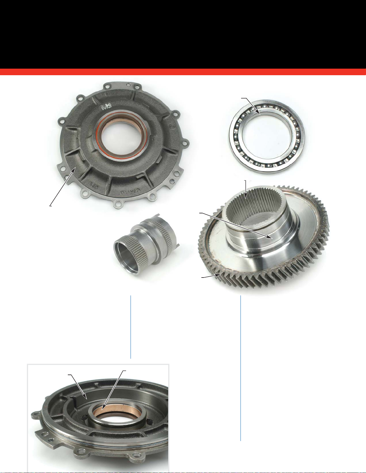
A. P3 Carrier
Assembly
(Non-Retarder)
B. Tapered
Roller
Bearing
D. P3 Planetary
Spindle
E. Thrust
Washer
G. Pinion
Roller
Bearing
I. Output Shaft
External
Retaining Ring
H. Output
Shaft
Spacer
J. Output Shaft
A.
Verify a proper press fit
between the P3 carrier and rear
cover or retarder housing by
inverting the carrier over a table or
workbench. If the P3 carrier falls
out of the rear cover or retarder
housing without using a press or
mallet, the press fit between the
tapered bearings and P3 carrier no
longer exists and the carrier must
be replaced.
Inspect the P3 carrier for spline
wear. Replace the carrier if spline
wear exceeds 0.38 mm (0.015 inch).
Inspect the pinion spindle bores in
the carrier and the pinion thrust
surfaces for excessive wear and
damage. Replace the P3 carrier if a
spindle has more than 0.051 mm
(0.002 inch) clearance in the bore.
Inspect for thread damage on the
carrier hub. Replace the carrier if
threads are damaged.
B. Inspect the tapered roller
bearings and races following the
“General Inspection Guidelines for
Bearings” section of this manual.
Replace any bearings failing to meet
the inspection guidelines. Bearing
races are located in the rear cover
housing and should also be
inspected for wear and damage.
C. Inspect the P3 indexing ring
for step wear in the area where it
contacts the spindle. Replace the
indexing ring if it is broken or if it
has excess step wear or damage
which cannot be repaired using a
soft stone or crocus cloth. Indexing
rings with acceptable wear can be
flipped during reassembly so that a
new contact surface is used.
Bearing races
located in rear
cover.
F. Pinion
Gear
C. Indexing
Ring
(continued)

D. Inspect planetary spindles for
wear and damage. Discoloration is
only a concern if spindle surface
damage exists.
E. Inspect the pinion gear thrust
washers for damage, distortion and
signs of excessive wear. Minimum
allowable thrust washer thickness
is 1.39 mm (0.054 inch). Replace
damaged or worn thrust washers.
F. Inspect the pinion gears
following the “General Inspection
Guidelines for Gears” section of this
manual. Replace any gears which
fail these inspection procedures or
if the damage cannot be repaired
using a soft stone.
G. Inspect the pinion roller
bearings following the “General
Inspection Guidelines for Bearings”
section of this manual. Replace any
bearings which fail these inspection
procedures.
H. Replace the output shaft
spacer if it is bent, cracked or if it
is distorted in any way. An attempt
can be made to repair some minor
damage using a soft stone.
I. Inspect the output shaft
external retaining ring. Replace
the retaining ring if it is distorted
or fits loosely on the shaft.
ALLISON 4000/B500 PRODUCT FAMILIES
STANDARD REAR COVER &
(continued)
P3 PLANETARY MODULE
35
2005 General Motors Corporation.
ALLISON TRANSMISSION TECHNICIANS’ GUIDE
Supersession Information
P3 Carrier Update SIL 25-WT-01
Current P3 carriers use a drill point
hole and a Belleville spring washer.
Supersession Information
Planetary Spindle and
Indexing Ring Updates SIL 10-WT-00
Planetary spindles and indexing rings are
backward compatible. Current spindles are
stamped with the number “2.” Indexing rings
are stamped with the identifier “HD5.”
P1 P2
P3
(continued)

36
2005 General Motors Corporation.
ALLISON TRANSMISSION TECHNICIANS’ GUIDE
J. Inspect the output shaft
following the “General Inspection
Guidelines for Cast Parts and
Machined Surfaces” and the
“General Inspection Guidelines for
Splines” sections of this manual.
Replace the output shaft if it fails
these inspection procedures.
Inspect the output shaft bushing
following the “General Inspection
Guidelines for Bushings” section of
this manual. Replace the bushing if
it fails these inspection procedures.
Maximum allowable bushing inside
diameter is 36.14 mm (1.423 inch).
ALLISON 4000/B500 PRODUCT FAMILIES
STANDARD REAR COVER &
P3 PLANETARY MODULE
(continued)
Supersession Information
Flange /Yoke Retaining Bolt Update - Reference SIL 1-WT-99
Single Bolt
design
increases
clamp load.
Output spacers
are not
interchangeable
between the
former and
current designs.
Supersession Information
Service Kit for Two-Bolt Ouput - SIL 15-WT-98
Kit Part Number: 29535910
J. Output Shaft
J. Inspect the output shaft
bushing for damage.
* Note: Kit contains
Belleville washers and
2 allen-head bolts to
replace original locking
tab and hex-head bolts.
(continued)

ALLISON 4000/B500 PRODUCT FAMILIES
STANDARD REAR COVER &
(continued)
P3 PLANETARY MODULE
37
2005 General Motors Corporation.
ALLISON TRANSMISSION TECHNICIANS’ GUIDE
K. Replace the output bearing
locknut retainer whenever the
locknut is removed.
L. Inspect the Belleville spring
washer for damage. Replace the
washer if it is distorted or the
tang is worn.
M. Replace the output bearing
locknut if it is cracked, distorted,
has damaged threads. The current
locknuts have three buttons in the
threaded area. This nut should be
replaced if it does not have a
minimum of 10 N.m (7.5 ft. lb.) of
running torque when threading
the nut.
(continued)
K. Locknut
Retainer
4000 Series
Wide Ratio
P3 Carrier
Assembly
4000 Series
Close Ratio
P3 Carrier
Assembly
Former output bearing
locknut and retainer
M.Output
Bearing
Locknut
L. Belleville
Spring

38
2005 General Motors Corporation.
ALLISON TRANSMISSION TECHNICIANS’ GUIDE
Supersession Information
ALLISON 4000/B500 PRODUCT FAMILIES
STANDARD REAR COVER &
P3 PLANETARY MODULE
(continued)
Supersession Information
Bearing Retainer Locknut
Update - Reference
SIL 25-WT-01
Current
bearing
retainer
locknuts
include
three
locking
buttons.
Supersession Information
Output Yoke/Flange Update Reference SIL 4-WT-03
Not all yoke / slinger combinations
can be used with all transmissions. Rear cover design determines yoke / slinger combination.
Supersession Information
Rear Cover Update - Reference SIL 4-WT-03
Current rear cover has interior cut relief to accommodate
5-ridge output seal. Former rear cover has interior cut relief to
accommodate 4-ridge output seal
(reference Output Seal Update
Supersession Information)
.
Former: No cut relief Current: Cut relief on
the exterior for a wrap
around slinger.
Former
Output Seal
Current Output Seal
(former
standard/ retarder housing)
for S/N prior to 6610116108
Current Output Seal
(current
standard/ retarder housing)
for
S/N starting with 6610116108
Output Seal Update Reference SIL 4-WT-03
Two seals are
currently available to fit former and
current rear covers.
They are NOT
interchangeable.

ALLISON 4000/B500 PRODUCT FAMILIES
RETARDER MODULE
39
2005 General Motors Corporation.
ALLISON TRANSMISSION TECHNICIANS’ GUIDE
A. Inspect the retarder housing
following the “General Inspection
Guidelines for Cast Parts and
Machined Surfaces” section of this
manual. High spots on machined
surfaces can be removed using a
soft stone or crocus cloth. Replace
the retarder housing if it is cracked
or if machined surface damage
cannot be removed using a soft
stone or crocus cloth.
Install a “known good” rotor
sealring in the retarder housing and
measure sealring inside diameter. If
the retarder housing is slightly
grooved or worn, place the sealring
directly in the grooved or worn
area. Replace the housing if sealring
inside diameter is greater than
139.72 mm (5.501 inches). A bearing
race fits into the housing and
should be inspected for damage.
B. Inspect the stator housing
following the “General Inspection
Guidelines for Cast Parts and
Machined Surfaces” section of this
manual. Some light housing
imperfections can be removed using
a soft stone. Discard and replace the
housing if damage is excessive.
NOTE: Transmissions built prior to
January 1998 included two small
check balls and retainers located in
the retarder stator housing.
Minimum allowable check ball
movement is 0.50 mm (0.020 inch).
Inspect the slot on the back side
of the housing where the C5 piston
tang indexes for excessive wear.
Replace the stator housing if
damage to any machined surface
cannot be repaired using a soft
stone or crocus cloth. Replace the
stator housing if it is cracked.
C. Inspect the retarder rotor
following the “General Inspection
Guidelines for Cast Parts and
Machined Surfaces” section of this
manual. Check for loose, cracked or
broken rivets. Replace the rotor if
movement exists between the
center hub and the vaned assembly.
Inspect the rotor splines for wear.
B. Retarder Stator
Housing
E. Autoflow V alve,
Spring & Plug
C. Retarder
Rotor
F. Retarder Temp
Sensor Assembly
A. Retarder
Housing
G. Output Speed
Sensor
(continued)
D. P3 Carrier
Assembly
(Retarder)
Supersession Information
Retarder Exhaust Backfill Valve Update Reference SIL 14-WT-02
The current stop is backward
compatible with all 4000/B500 retarder equipped transmissions.
Current
Retarder
Exhaust
Backfill
Valve Stop
Former
Retarder
Exhaust
Backfill
Valve Stop

40
2005 General Motors Corporation.
ALLISON TRANSMISSION TECHNICIANS’ GUIDE
Fluid Flow
Detail
ALLISON 4000/B500 PRODUCT FAMILIES
RETARDER MODULE
(continued)
Spline wear cannot exceed 0.38 mm
(0.015 inch). Replace the rotor if it
exceeds this wear limit.
D. Reference the “Inspection and
Analysis of the Standard Rear
Cover” section of this manual for P3
planetary carrier assembly details.
NOTE: Inspect retarder P3 carriers
for excessive step wear on the
splines of the P3 carrier hub.
Replace those P3 carriers that
exhibit step wear.
E. Inspect the retarder autoflow
valve for wear and damage. The
autoflow valve must move freely in
its bore, when dry, under its own
weight. Replace or repair the
autoflow valve and/or retarder
housing as necessary. Crocus cloth
can be used to remove slight high
spots.
Inspect the autoflow valve spring
for defects and permanent set.
Reference the Spring Data Charts in
Service Manual SM2457 for spring
specifications and identification.
Replace the spring if it fails any
inspection procedures.
F. Inspect the retarder
temperature sensor exterior for
defects. Replace the temperature
sensor if it is damaged. There are
two temperature sensor types - TID
1 and post-TID 1 (TID 2 and TID 3).
Resistance specifications vary
between the two sensor types. Be
sure to use the correct
Troubleshooting Manual chart for
the sensor being tested. Replace the
temperature sensor if its measured
resistance is not within
Troubleshooting Manual
specifications.
G. Inspect the output speed
sensor for damage. Replace the
sensor if it has body, terminal or
connector seat damage. Allowable
output speed sensor resistance is
300 ohms plus or minus 30 ohms.
Supersession Information
Retarder Sump Cooling Feature - Reference
SIL 25-WT-00, Rev. A
The sump cooling feature provides additional cooling
when the retarder is active through either an additional
auxiliary cooler or the direct mount cooler for retarder
transmissions.The direct mount cooler for retarder transmissions
works as both the main cooler and auxiliary cooler.
(continued)
Main
Control
Main
From
Cooler
To Cooler
C5 Pressure
Exhaust
Retarder
Out
Accumulator
Converter Out
(To Cooler)
Lube
Pressure
From
Cooler
To Retarder
Control Main
Main
No Sump
Cooling
Feature
Sump
Cooling
Provision

ALLISON 4000/B500 PRODUCT FAMILIES
(continued)
RETARDER MODULE
41
2005 General Motors Corporation.
ALLISON TRANSMISSION TECHNICIANS’ GUIDE
A. Inspect the retarder control
valve body following the “General
Inspection Guidelines for Cast
Parts and Machined Surfaces”
section of this manual. All passages
must be clean and debris free. Valve
bores must be free of nicks, burrs
and scoring. Crocus cloth or a soft
stone can be used to attempt
removal of slight irregularities,
however no honing of any kind is
permitted.
B & H. Inspect the retarder
control valve and exhaust backfill
valve for nicks, burrs, scoring and
other damage. A soft stone or
crocus cloth can be used to attempt
removal of slight irregularities.
Valves must move freely in their
bores, when dry, under their own
weight.
C & I. Replace the retarder
control valve spring or exhaust
backfill spring for damage or
permanent set. Reference the
Spring Data Charts in the Service
Manual for spring specifications
and identification.
D. Inspect the valve plug for
damage. Replace the plug if damage
cannot be repaired using a soft
stone or crocus cloth.
E. Inspect the channel plate
following the “General Inspection
Guidelines for Cast Parts and
Machined Surfaces” section of this
manual. Replace the channel plate if
it fails any of these inspection
procedures or if it has damage
which cannot be repaired using a
soft stone or crocus cloth.
All passages must be clean and
debris free.
K. Wiring
Harness
A. Retarder
Valve
Body
G. Retarder
Solenoid
H. Exhaust
Backfill
Valve
I. Exhaust
Backfill
Valve
Spring
L. Solenoid
Cover
E. Channel
Plate
C. Retarder Control
Valve Spring
F. Separator
Plate
J. Exhaust
Backfill V alve
Stop & Pin
D. Valve
Plug &
Retaining
Ring
B. Retarder
Control
Valve
(continued)

42
2005 General Motors Corporation.
ALLISON TRANSMISSION TECHNICIANS’ GUIDE
ALLISON 4000/B500 PRODUCT FAMILIES
RETARDER MODULE
(continued)
F. Inspect the separator plate for
nicks, burrs, scoring and distortion
(flatness). Replace the plate if
damage cannot be repaired using a
soft stone or crocus cloth.
G. Replace the retarder solenoid
if the body, connector or terminals
show visible signs of damage.
Solenoid resistance should be 3 to 4
ohms measured between the two
solenoid terminals. Check
resistance between each solenoid
terminal and the solenoid body.
Replace the solenoid if either
reading is less than 100k ohms
resistance.
J. Inspect the exhaust backfill
valve stop for damage. Replace the
stop if damage cannot be repaired
using a soft stone or crocus cloth.
Inspect the exhaust backfill valve
pin for damage. Replace the pin if it
is bent or has damage.
K. Replace or repair the wiring
harness if the wires, terminals or
connectors are visibly damaged.
Check the installed harness for
tight bends or crimps which might
damage harness wires.
L. Inspect the solenoid cover
following the “General Inspection
Guidelines for Cast Parts and
Machined Surfaces” section of this
manual. Replace the housing if it
fails any of these inspection
procedures.
Exhaust
Pressure
Retarder
Pressure
Pocket
Main
Pressure
Control
Main
Retarder
Pressure
Exhaust
Pressure
Pocket
Retarder
Pressure
Main
Pressure
Exhaust
Pressure
Exhaust
Backfill
Pressure
Exhaust
Pressure
Retarder
Pressure
Main
Pressure
(to Flow
Valve)
Main Pressure
(Feed)
Control Main
Pressure

ALLISON 4000/B500 PRODUCT FAMILIES
CLOSE RATIO MAIN SHAFT MODULE
43
2005 General Motors Corporation.
ALLISON TRANSMISSION TECHNICIANS’ GUIDE
A. Main Shaft
H. P3
Sun
Gear
D. Thrust
Bearing
F. Bearing
Spacer
G. Selective
Shim
E. P2 Sun
Gear
I. Spiral
Retaining
Ring
B. Main
Shaft
Pilots
C. Journal
B. Main
Shaft
Pilots
A. Inspect the main shaft
following the “General Inspection
Guidelines for Gears” and “General
Inspection Guidelines for Splines”
sections of this manual. Replace the
main shaft if it fails any of these
inspection procedures.
B. Inspect the front and rear
main shaft pilots for damage. The
front main shaft pilot fits inside the
turbine shaft. The rear main shaft
pilot fits inside the output shaft.
Replace the main shaft if pilot
outside diameter is less than 35.92
mm (1.414 inch).
C. Inspect the P2 bushing journal
area for damage. Replace the main
shaft if P2 planetary bushing
journal diameter is less than 52.98
mm (2.085 inch).
D. Inspect the thrust bearings
following the “General Inspection
Guidelines for Bearings” section of
this manual. Replace any bearing
that fails any of these inspection
procedures.
E. Inspect the P2 sun gear
following the “General Inspection
Guidelines for Gears” and “General
Inspection Guidelines for Splines”
sections of this manual. Replace the
gear if it fails any of these inspection
procedures.
F. Inspect the main shaft bearing
spacer following the “General
Inspection Guidelines for Cast Parts
and Machined Surfaces” and
“General Inspection Guidelines for
Splines” sections of this manual.
Replace the spacer if it fails any of
these inspection procedures.
G. Inspect the selective shim for
damage. Replace the shim if it is
distorted or if damage cannot be
removed by light stoning.
H. Inspect the P3 sun gear
following the “General Inspection
Guidelines for Gears” and “General
Inspection Guidelines for Splines”
sections of this manual. Replace the
gear if it fails any of these
inspection procedures.
I. Replace the spiral retaining
ring if it is removed.
Close Ratio Main
Shaft Module

44
2005 General Motors Corporation.
ALLISON TRANSMISSION TECHNICIANS’ GUIDE
ALLISON 4000/B500 PRODUCT FAMILIES
WIDE RATIO MAIN SHAFT MODULE
A. Main
Shaft
D. P2 Sun
Gear
E. Thrust
Bearing
F. Bearing
Spacer
G. Selective
Shim
H. Spiral
Retaining
Ring
B. Main Shaft
Pilots
C. Journal
B. Main Shaft Pilots
A. Inspect the main shaft
following the “General Inspection
Guidelines for Gears” and “General
Inspection Guidelines for Splines”
sections of this manual. Replace the
main shaft if it fails any of these
inspection procedures.
B. Inspect the front and rear main
shaft pilots for damage. The front
main shaft pilot fits inside the
turbine shaft. The rear main shaft
pilot fits inside the output shaft.
Replace the main shaft if pilot
outside diameter is less than 35.92
mm (1.414 inch).
C. “Inspect the P2 bushing
journal for damage. Replace the
main shaft if P2 planetary bushing
journal diameter is less than 52.98
mm (2.085 inch).
D. Inspect the P2 sun gear
following the “General Inspection
Guidelines for Gears” and “General
Inspection Guidelines for Splines”
sections of this manual. Replace the
gear if it fails any of these
inspection procedures.
E. Inspect the thrust bearings
following the “General Inspection
Guidelines for Bearings” section of
this manual. Replace any bearing that
fails any of these inspection
procedures.
F. Inspect the main shaft bearing
spacer following the “General
Inspection Guidelines for Cast
Parts and Machined Surfaces”
“General Inspection Guidelines for
Splines” sections of this manual.
Replace the spacer if it fails any of
these inspection procedures.
G. Inspect the selective shim for
damage. Replace the shim if it is
distorted or if damage cannot be
removed by light stoning.
H. Replace the spiral retaining
ring if it is removed.
Wide Ratio Main
Shaft Module

D. P3 Ring
Gear
A. P2 Planetary
Carrier
E. Index
Ring
F. Pinion Thrust
Washers
G. Pinion
Spindle
H. Pinion
Roller
Bearings
I. Pinion
Gear
J. Retaining
Rings
A. Inspect the P2 carrier
following the “General Inspection
Guidelines for Cast Parts and
Machined Surfaces” and the
“General Inspection Guidelines for
Splines” sections of this manual.
Replace the carrier if any spindle
has more than 0.051 mm (0.002
inch) clearance in its bore.
B. Inspect the P2 carrier bushing
for damage. Replace the bushing if
damaged. Replace the bushing if
inside diameter exceeds 53.23 mm
(2.096 inches).
C. Inspect the carrier hub for
damage. Replace the carrier if
damage cannot be repaired using a
soft stone or crocus cloth.
D. Inspect the P3 ring gear
following the “General Inspection
Guidelines for Gears” and “General
Inspection Guidelines for Splines”
sections of this manual. Replace the
ring gear if it fails any of these
inspection procedures.
E. Inspect the P2 indexing ring for
step wear in the area where it
contacts the spindle. Replace the
indexing ring if it is broken or if it
has excessive step wear or damage.
Indexing rings with acceptable
wear can be flipped during
reassembly so that a new contact
surface is used.
F. Replace the pinion gear thrust
washers if they are damaged,
distorted, galled or showing signs of
excessive wear. Minimum allowable
thrust washer thickness is 1.40 mm
(0.055 inch). Maximum allowable
thrust washer step wear is 0.12 mm
(0.005 inch).
G. Replace planetary spindles if
they are worn or damaged.
Discoloration is only a concern if
spindle surface damage exists.
ALLISON 4000/B500 PRODUCT FAMILIES
P2 PLANETARY MODULE
45
2005 General Motors Corporation.
ALLISON TRANSMISSION TECHNICIANS’ GUIDE
B. Carrier
Bushing
C. Carrier
Hub
(continued)

46
2005 General Motors Corporation.
ALLISON TRANSMISSION TECHNICIANS’ GUIDE
ALLISON 4000/B500 PRODUCT FAMILIES
P2 PLANETARY MODULE
(continued)
H. Inspect the pinion roller
bearings following the “General
Inspection Guidelines for Bearings”
section of this manual. Replace any
bearing failing these inspection
procedures.
I. Inspect the P2 pinion gears
following the “General Inspection
Guidelines for Gears” section of this
manual. Replace any gear that fails
these inspection procedures or if
damage cannot be removed using a
soft stone.
J. Inspect the P2 carrier
retaining rings for damage or
distortion. Replace any retaining
rings with damage that cannot be
removed using a soft stone.
NOTE: Current P3 ring gears are
hardened. Former P3 ring gears
were non-hardened. Each ring gear
requires a specific C5 clutch plate.
There are two current versions of
C5 clutch plates. Plates which are
missing two splined teeth must be
used with the hardened P3 ring gear
(identified by the groove on the
gear’s outside diameter). Plates
missing three splined teeth must be
used with the non-hardened P3 ring
gear (no identification groove).
Reference the C5 clutch plate
“Supersession Information” in this
section and SILs 12-WT-03 and
4-WT-00, Revision B. The correct
current C5 clutch plate must be
used with each ring gear to avoid
transmission damage.
Supersession Information
Planetary Spindle and Indexing Ring
Updates - Reference SIL 10-WT-00
Planetary spindles and indexing rings are
backward compatible. Current spindles are
stamped with the number “2.” Indexing rings
are stamped with the identifier “HD5.”
P1
P2
P3
FORMER (NON-HARDENED)
P3 RING GEAR
HARDENED
P3 RING GEAR
IDENTIFICATION
GROOVE
Supersession Information
P3 Ring Gear Update SIL 12-WT-03
Use C5 friction
plate missing 2
internal teeth.
Use C5 friction
plate missing
3 internal teeth.
4000 Series
Close Ratio
P2 Carrier
Assembly
4000 Series
Wide Ratio
P2 Carrier
Assembly

A. P1
Planetary
Carrier
B. P2
Ring
Gear
C. Index
Ring
D. Pinion
Thrust
Washers
E. Pinion
Spindle
G. Pinion Roller
Bearings
F. Pinion
Gear
H. Retaining
Ring
A. Inspect the P1 carrier following
the “General Inspection Guidelines
for Cast Parts and Machined
Surfaces” and the “General
Inspection Guidelines for Splines”
sections of this manual. Replace the
carrier if any spindle has more than
0.051 mm (0.002 inch) clearance in
its bore.
Thrust bearings fit on both sides of
the P1 carrier. Inspect the thrust
bearings following the “General
Inspection Guidelines for Bearings”
section of this manual. Replace any
bearing that fails any of these
inspection procedures.
B. Inspect the P2 ring gear
following the “General Inspection
Guidelines for Gears” and the
“General Inspection Guidelines for
Splines” sections of this manual.
Replace the ring gear if it fails any
of these inspection procedures.
C. Inspect the P1 indexing ring
for step wear in the area where it
contacts the spindle. Replace the
indexing ring if it is broken or if it
has excessive step wear or damage.
Indexing rings with acceptable
wear can be flipped during
reassembly so that a new contact
surface is used.
ALLISON 4000/B500 PRODUCT FAMILIES
P1 PLANETARY MODULE
47
2005 General Motors Corporation.
ALLISON TRANSMISSION TECHNICIANS’ GUIDE
Thrust
bearing
inspection.
(continued)
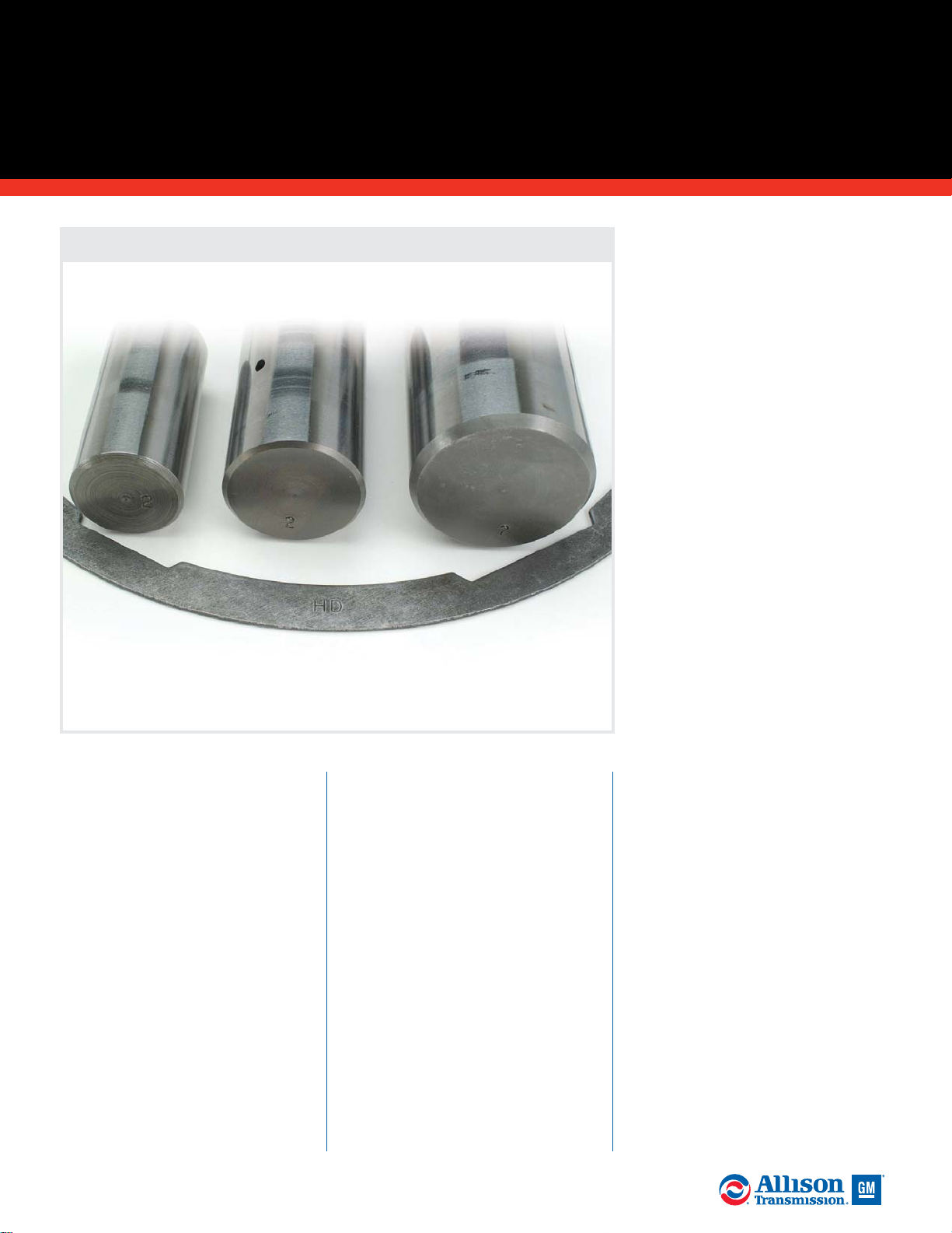
48
2005 General Motors Corporation.
ALLISON TRANSMISSION TECHNICIANS’ GUIDE
ALLISON 4000/B500 PRODUCT FAMILIES
P1 PLANETARY MODULE
(continued)
D. Replace the pinion gear thrust
washers if they are damaged,
distorted, galled or showing signs of
excessive wear. Minimum allowable
thrust washer thickness is 1.39 mm
(0.054 inch).
E. Replace planetary spindles if
they are worn or damaged.
Discoloration is only a concern if
spindle surface damage exists.
F. Inspect the P1 pinion gears
following the “General Inspection
Guidelines for Gears” section of this
manual. Replace any gear that fails
these inspection procedures or if
damage cannot be removed using a
soft stone.
G. Inspect the pinion roller
bearings following the “General
Inspection Guidelines for Bearings”
section of this manual. Replace any
bearing failing these inspection
procedures.
H. Inspect the P1 carrier retaining
rings for damage or distortion.
Replace any retaining rings with
damage that cannot be removed
using a soft stone.
Supersession Information
Planetary Spindle and Indexing Ring Updates SIL 10-WT-00
Planetary spindles and indexing rings are backward
compatible. Current spindles are stamped with the number
“2.” Indexing rings are stamped with the identifier “HD5.”
P1 P2
P3

A. Front Support
Assembly
D. PTO-Model
Ground
Sleeve
F. Charging
Pump
Housing
(PTO Model)
H. Roller
Bearing
G. Main
Pressure
Relief Ball
& Spring
J. Wear
Plate
D. Non-PTO Model
Ground Sleeve
E. Bushing
Journal
I. Charging Pump
Gear Set
A. Inspect the front support
assembly following the “General
Inspection Guidelines for Cast
Parts and Machined Parts” section
of this manual. Replace the
assembly if it fails any of these
inspection procedures. If the
ground sleeve has rotated in the
front support, replace both
components (the ground sleeve and
the front support assembly). If the
ground sleeve is replaced, check the
front support for flatness after
ground sleeve installation. Replace
the front support if it is more than
0.051 mm (0.002 inch) from flat.
B. Replace the front support if
the sleeve has damage that cannot
be repaired using a soft stone or
crocus cloth. Minimum allowable
front support sleeve diameter is
119.81 mm (4.717 inches).
C. Inspect the three sealring
grooves on the front support
assembly hub for nicks, burrs,
cracks and other damage.
ALLISON 4000/B500 PRODUCT FAMILIES
FRONT SUPPORT &
OIL PUMP MODULE
49
2005 General Motors Corporation.
ALLISON TRANSMISSION TECHNICIANS’ GUIDE
Supersession Information
Redesigned Charging Pump
Gear Set - SIL 13-WT-04
Orange bushing identifies
current gear set.
C. Sealring Grooves
B. Front
Support
Sleeve
B. Front
Support
Sleeve
Former
Current
(continued)

50
2005 General Motors Corporation.
ALLISON TRANSMISSION TECHNICIANS’ GUIDE
ALLISON 4000/B500 PRODUCT FAMILIES
FRONT SUPPORT & OIL PUMP MODULE
(continued)
Oil Passage
Detail
Lube
Pressure
Main
Pressure
Lockup Pressure
Converter
Out
Converter In
Pump
Suction
C1
Pressure
D.
Inspect the ground sleeve
following the “General Inspection
Guidelines for Splines” section of
this manual. Replace the shaft if it
fails any of these inspection
procedures.
E. Inspect the journal area where
the charging pump driven gear
bushing rides. Replace the shaft if
the journal is damaged or galled.
Minimum allowable journal
diameter is 66.67 mm (2.265
inches).
NOTE: Ground sleeve galling is
typically an indicator of poor
transmission fluid condition due to
improper maintenance intervals.
Observation of proper fluid change
intervals is key to optimum
transmission life.
Inspect the area in the ground
sleeve where the turbine shaft
sealrings ride for grooves, scoring
and other wear or damage. Install
new sealrings in the ground sleeve
and measure the end gap. If the
ground sleeve is grooved or worn,
place the sealrings directly in the
grooved or worn area. Maximum
allowable sealring end gap is 1.01
mm (0.039 inches). Replace the
ground sleeve if any of the seal ring
end gaps exceeds this specification.
NOTE: When replacing the ground
sleeve, total shaft runout cannot
exceed 0.30 mm (0.012 inch) once it
is pressed into the front support.
C2
Pressure
(continued)
C1 Pressure
C2 Pressure
Front support oil passage
detail - outside hub.
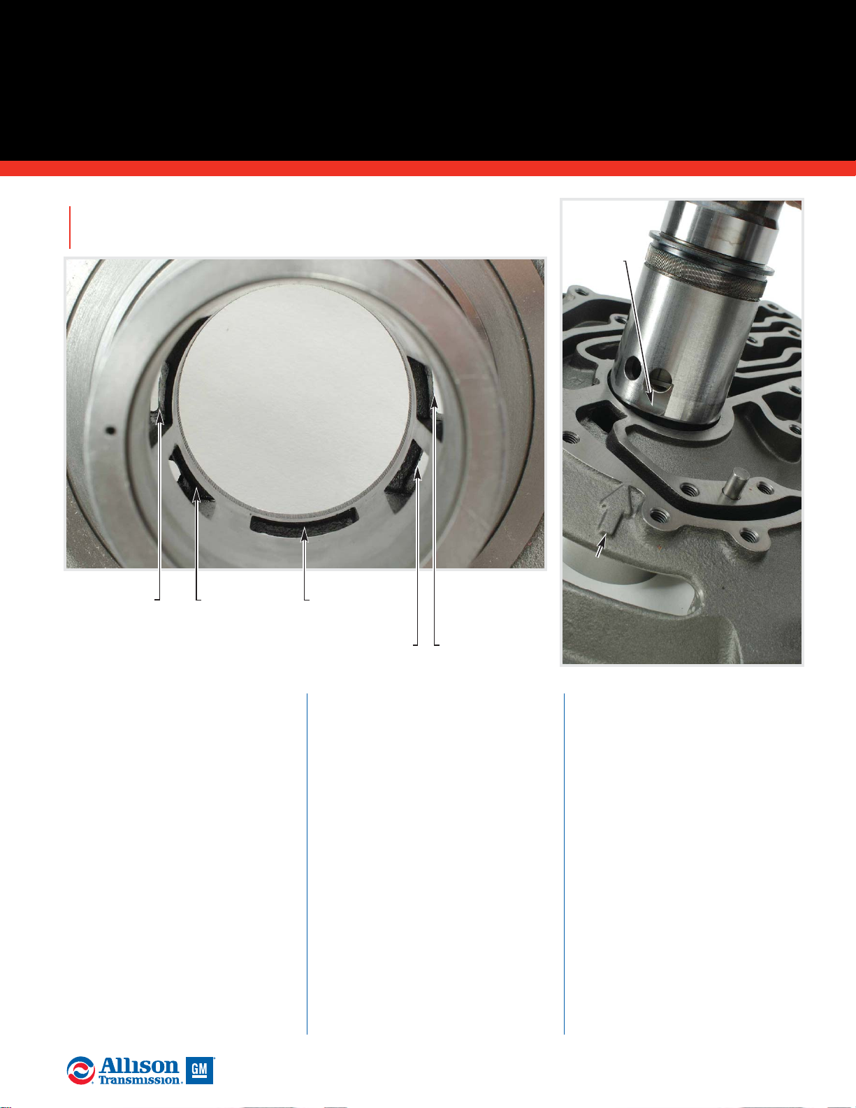
F. Inspect the charging pump
housing following the “General
Inspection Guidelines for Cast
Parts and Machined Parts” section
of this manual. Replace the housing
if it fails any of these inspection
procedures. Replace the charging
pump housing if gear cavity depth
exceeds 19.04 mm (0.750 inches).
Replace the charging pump housing
if gear cavity diameter exceeds
150.25 mm (5.915 inches).
G. Replace the main pressure
relief ball if it is damaged. Inspect
the main pressure relief spring
following the “General Inspection
Guidelines for Springs” section of
this manual. Replace the spring if it
is bent, broken, distorted or shows
signs of wear from rubbing adjacent
parts. Reference the Spring Data
Charts in the Service Manual for
spring identification and
specifications.
H. The roller bearing fits inside
the back of the front support hub.
Inspect this bearing following the
“General Guidelines for Bearings”
section of this manual. Replace the
bearing if it fails any of these
inspection procedures.
ALLISON 4000/B500 PRODUCT FAMILIES
(continued)
FRONT SUPPORT & OIL PUMP MODULE
51
2005 General Motors Corporation.
ALLISON TRANSMISSION TECHNICIANS’ GUIDE
(continued)
Oil passage detail -
inside hub.
Lube
Lockup
Converter
Out
C1
Pressure
C2 Pressure
Indexing
Alignment
Arrow
Flat on
Ground
Sleeve

52
2005 General Motors Corporation.
ALLISON TRANSMISSION TECHNICIANS’ GUIDE
Ground sleeve oil
passage detail.
ALLISON 4000/B500 PRODUCT FAMILIES
FRONT SUPPORT & OIL PUMP MODULE
(continued)
Lube
Lockup
Converter Out
C2 Pressure
C1
Pressure
I. Replace the charging pump
gear set if the sides, faces or gear
teeth are damaged. Replace the gear
set if the inside gear shows damage
or battering at the point where the
torque converter drive tangs (or the
PTO drive hub tangs) index into
the gear. Replace the gear set if the
bushing inside diameter exceeds
57.30 mm (2.256 inch). Minimum
allowable outside diameter of the
outer gear is 149.94 mm (5.903
inch).
NOTE: Install the pump gear set in
the oil pump housing to perform
the following inspections and
measurements.
Maximum allowable clearance
between the installed gear set and
mounting face of the pump housing
is 0.10 mm (0.004 inch). This is
often referred to as pump gear side
clearance. Maximum allowable gear
tooth tip clearance (the gap
between a tooth on the outer gear
and a tooth on the inner gear) is
0.15 mm (0.006 inch). The
maximum allowable clearance
between the outer gear and the
pump housing is 0.30 mm (0.012
inch).
J. Replace the wear plate if it is
galled or moderately scored. Pay
particular attention to the area
where the charging pump gear set
rides. Minimum allowable wear
plate thickness is 4.70 mm (0.0185
inch). Replace the wear plate if it is
worn past service limits or if it has
damage that cannot be repaired
using a soft stone or crocus cloth.

A. Inspect the turbine shaft
following the “General Inspection
Guidelines for Cast Parts and
Machined Surfaces” section of this
manual. Replace the turbine shaft if
it fails any of these inspection
procedures. Maximum allowable
spline wear is 0.38 mm (0.015 inch).
B. Inspect the turbine shaft
bushing following the “General
Inspection Guidelines for Bushings”
section of this manual. Replace the
bushing if it fails any of these
inspection procedures. Maximum
allowable bushing inside diameter
is 36.14 mm (1.423 inch).
C. Inspect the bearing
journal area for damage.
Replace the turbine shaft if
damage cannot be repaired
with a light stone or crocus
cloth.
D. Inspect the three sealring
grooves for damage. Replace the
turbine shaft if damage cannot be
repaired with a light stone or
crocus cloth. Install three new
sealrings and check end gap.
Minimum end gap allowed is 0.65
mm (0.026 inch). Replace turbine
shaft if end gap is below minimum.
E. Inspect the rotating drum
following the “General Inspection
Guidelines for Cast Parts and
Machined Surfaces” and “General
Inspection Guidelines for Splines”
sections of this manual. Replace the
drum if it fails any of these
inspection procedures. Maximum
allowable spline wear is 0.38 mm
0.015 inch).
F. Inspect the rotating clutch
hub following the “General
Inspection Guidelines for Cast
Parts and Machined Surfaces” and
ALLISON 4000/B500 PRODUCT FAMILIES
ROTATING CLUTCH MODULE
53
2005 General Motors Corporation.
ALLISON TRANSMISSION TECHNICIANS’ GUIDE
A. Turbine Shaft
(PTO Model)
G. P1 Sun
Gear
Assembly
H. Thrust
Bearing
F. Rotating
Clutch Hub
E. Rotating
Drum
A. Turbine Shaft
(Non-PTO Model)
H. Thrust
Bearing
(continued)
J. Sealring
Bore
K. Bushing
C. Journal
B. Bushing
D. Sealring
Grooves
I. Retaining Ring

54
2005 General Motors Corporation.
ALLISON TRANSMISSION TECHNICIANS’ GUIDE
“General Inspection Guidelines for
Splines” sections of this manual.
Replace the hub if it fails any of
these inspection procedures.
G. Inspect the P1 sun gear
assembly following the “General
Inspection Guidelines for Gears and
“General Inspection Guidelines for
Splines” sections of this manual.
Replace the assembly if it fails any
of these inspection procedures or if
it has damage which cannot be
repaired using a soft stone or crocus
cloth.
H. Inspect the thrust bearings
following the “General Inspection
Guidelines for Bearings” section of
this manual. Replace any bearings
which fail any of these inspection
procedures.
I. Inspect the turbine shaft
retaining ring following the
“General Inspection Guidelines for
Retaining Rings” section of this
manual. Replace the retaining ring
if it fails any of these inspection
procedures or if the ring is bent,
distorted or shows other signs of
damage.
J. Inspect the area inside the hub
where the front support sealrings
ride for grooves and damage.
Replace the hub if damage cannot
be repaired using a soft stone or
crocus cloth. Install three new
sealrings in the wear area of the
bore and check each seal’s end gap.
Replace the rotating clutch hub if
end gap exceeeds 1.44 mm (0.056
inch).
K. Inspect the rotating hub
bushing following the “General
Inspection Guidelines for Bushings”
section of this manual. Replace the
bushing if it fails any of these
inspection procedures or if it has
damage which cannot be repaired
using a soft stone or crocus cloth.
Maximum allowable bushing inside
diameter is 120.27 mm (4.735 inch).
ALLISON 4000/B500 PRODUCT FAMILIES
ROTATING CLUTCH
MODULE
(continued)
C1 Pressure
C2 Pressure
Rotating
clutch hub
oil passage
detail.
C1 Pressure
C2 Pressure
Supersession Information
Turbine Shaft Update Reference SIL 19-WT-94
Former turbine shaft and
current ground sleeve are
NOT compatible.
Supersession Information
Rotating Clutch Hub Update Reference SIL 8-WT-99, Rev. A
Supersession Information
Turbine Shaft Update Reference SIL 19-WT-94
& 22-WT-94
Former turbine shafts include a
raised area toward the torque
converter end of the shaft.
Former
Turbine
Shaft
Current
Turbine
Shaft
Former
(No Weld)
Current
(Weld)
Turbine Shaft
Ground Sleeve
(continued)
Note:The rotating clutch hub was
updated beginning with serial number
6610037353.The former rotating clutch
hub is not welded in the area shown.
The current rotating hub is welded and
machined in the area shown.

H. Thrust
Bearings
F. C1 Apply
Plate
A. C1
Drive
Hub
G. C1 Clutch
Pack
B. C1 Piston
E. C1 Backing
Plate
D. C1
Return
Spring
C1 Clutch
Components
A. Inspect the C1 drive hub
following the “General Inspection
Guidelines for Cast Parts and
Machined Surfaces” and the
“General Inspection Guidelines for
Splines” sections of this manual.
Replace the hub if it fails any of
these inspection procedures.
Maximum allowable spline wear is
0.38 mm (0.015 inch).
B & C. Inspect the C1 clutch
piston and C1 balance piston
following the “General Inspection
Guidelines for Cast Parts and
Machined Surfaces” section of this
manual. Replace any component if
it fails any of these inspection
procedures.
NOTE: Aluminum castings (like
clutch housings) can be etched by
caustic parts cleaners and solvents.
Etched components are identified
by a dull to dark gray color - not the
bright finish of a normal machined
aluminum part. Etched components
are also identified by roughness in
the piston seal surface which can
cause piston seals to abrade and
result in low clutch apply pressure
and transmission damage. Replace
etched or damaged components.
D. Replace the C1 return spring
assembly if it has permanent spring
set, wear due to rubbing adjacent
parts or if springs are cracked or
broken in any way. Reference the
Spring Data Charts in the Service
Manual for spring specifications
and identification.
E & F. Inspect the C1 pressure
plate and C1 backplate for flatness,
galling and other damage. Replace
any plate with damage which
cannot be removed using a soft
stone or crocus cloth. Former C1
pressure plate minimum allowable
thickness is 7.90 mm (0.311 inch).
Current C1 apply plate minimum
allowable thickness is 5.90 mm
(0.232 inch). Current C1 backplate
minimum allowable thickness is
9.90 mm (0.390 inch). Maximum
allowable distortion of all plates is
0.15 mm (0.006 inch).
ALLISON 4000/B500 PRODUCT FAMILIES
(continued)
ROTATING CLUTCH MODULE
55
2005 General Motors Corporation.
ALLISON TRANSMISSION TECHNICIANS’ GUIDE
(continued)
Housing in good condition - reuse.
Etched housing - do NOT use.
C. C1 Balance
Piston

56
2005 General Motors Corporation.
ALLISON TRANSMISSION TECHNICIANS’ GUIDE
NOTE: Transmissions built prior to
S/N 6610032320 used two identical
C1 pressure plates. Transmissions
built after that used different plates.
The current C1 apply pressure plate
(next to the C1 piston) is
approximately 2 mm thinner and
has a different shape than the
current C1 backplate (opposite end
of the C1 clutch pack). When
replacing the former pressure plates
in a transmission with the current
plate, both current plates must be
used. Mixing former and current
plates will result in C1 clutch
failure.
G. Inspect the C1 clutch friction
plates following the “General
Inspection Guidelines for Friction
Plates” section of this manual.
Replace any plates failing these
inspection procedures. Minimum
allowable friction plate thickness is
2.92 mm (0.115 inch). Minimum
allowable oil groove depth is 0.20
mm (0.008 inch). Maximum
allowable plate coning is 0.25 mm
(0.010 inch).
NOTE: Battered and worn spline
teeth may be an indicator of
driveline issues. Replace the clutch
plates and check the driveline.
NOTE: The current clutch friction
plates were implemented April of
2000 starting with s/n 6610062126.
Current clutch friction plates will
have two or more missing splines.
Former friction plates will either
have one spline missing or none
missing. Any 4000/B 500 model
transmission may be updated from
former C5 friction plates to current
C5 frictions without recalibrating
the transmission ECU. The rest of
the clutches in the main housing
(C1 through C4) must be updated
with current friction plates if any
other individual clutch besides C5
is updated from former to current
friction plates. Any update from
former frictions to current frictions
in C1 through C4 for a 4000 Series
or B500 with a WTEC II ECU will
require a new ECU calibration from
Allison Transmission. Any update
ALLISON 4000/B500 PRODUCT FAMILIES
ROTATING CLUTCH MODULE
(continued)
Supersession Information
C1 Drive Hub Update - Reference SIL 26-WT-04
Drill point identifies the current hub which is
backward compatible.
Supersession Information
C1 Clutch Piston and Balance
Piston Re-design - Reference
SIL 30-WT-04
Former and current components
can NOT be mixed.
Former: C1
Drive Hub
Current: C1
Drive Hub
Drill Point
Identifier
(continued)

ALLISON 4000/B500 PRODUCT FAMILIES
(continued)
ROTATING CLUTCH MODULE
57
2005 General Motors Corporation.
ALLISON TRANSMISSION TECHNICIANS’ GUIDE
from former frictions to current
frictions in C1 through C4 for a
4000 Series or B500 with a WTEC
III ECU with a calibration prior to
October 25, 1999 will require an
updated ECU calibration from
Allison Transmission. Do not
intermix both former and current
friction plates in a clutch pack.
The P3 ring gear changed to a
harder ring gear on s/n 6610027070.
The current P3 ring gear identifier
is a groove machined around the
outer diameter of the gear. The P3
ring gear with a groove identifier
requires the C5 friction with two
missing splines if updating from
former C5 frictions. If any
4000/B500 series model without
the harder ring gear (no groove on
O.D.) is being updated with current
C5 frictions, then it will require the
C5 friction that has three missing
internal splines. The C5 friction
plate missing three splines will
exhibit spline wear if used with the
current P3 ring gear with a groove
identifier on the O.D. The former P3
ring gear (no groove on O.D.) will
exhibit premature wear if used with
the current C5 friction with two
missing internal splines. No ECU
calibration is necessary for
updating C5 clutch plates.
Inspect the C1 clutch reaction
plates following the “General
Inspection Guidelines for Reaction
Plates” section of this manual.
Replace any plates failing these
inspection procedures. Minimum
allowable reaction plate thickness
is 2.41 mm (0.095 inch). Maximum
allowable reaction plate coning is
0.25 mm (0.010 inch).
H. Inspect the thrust bearings
following the “General Inspection
Guidelines for Bearings” section of
this manual. Replace any bearings
which fail any of these inspection
procedures.
Supersession Information
C1 Backing and Apply Plate Updates Reference SIL 22-WT-98, Rev. A
Former and current
components can NOT be mixed
(continued)
5.90 mm
9.90 mm

58
2005 General Motors Corporation.
ALLISON TRANSMISSION TECHNICIANS’ GUIDE
ALLISON 4000/B500 PRODUCT FAMILIES
ROTATING CLUTCH MODULE
(continued)
A. Inspect the C2 drive hub
following the “General Inspection
Guidelines for Cast Parts and
Machined Surfaces” and the
“General Inspection Guidelines for
Splines” sections of this manual.
Replace the hub if it fails any of
these inspection procedures.
Maximum allowable spline wear is
0.38 mm (0.015 inch).
B. Inspect the C2 clutch piston
following the “General Inspection
Guidelines for Cast Parts and
Machined Surfaces” section of this
manual. Replace the piston if it fails
any of these inspection procedures.
NOTE: Aluminum castings (like
clutch housings) can be etched by
caustic parts cleaners and solvents.
Etched components are identified
by a dull to dark gray color - not the
bright finish of a normal machined
aluminum part. Etched components
are also identified by roughness in
the piston seal surface which can
cause piston seals to abrade and
result in low clutch apply pressure
and transmission damage. Replace
etched or damaged components.
C. Replace the C2 return spring
assembly if it has permanent spring
set, wear due to rubbing adjacent
parts or if springs are cracked or
broken in any way. Reference the
Spring Data Charts in the Service
Manual for spring specifications
and identification.
D. Replace the C2 spring plate if
it is cracked, broken or showing
any signs of distortion or wear.
E. Inspect the C2 backplate for
damage. Replace the plate if damage
cannot be removed using a soft
stone or crocus cloth. C2 backplate
minimum allowable thickness is
7.90 mm (0.311 inch) when
measured at the backing plate wear
area. Maximum allowable
distortion from flat is 0.015 mm
(0.006 inch).
G. Thrust
Bearing
B. C2 Piston
A. C2
Drive
Hub
E. C2 Backplate
C. C2 Return
Spring
D. C2 Spring
Plate
C2 Clutch
Components
(continued)
Housing in good condition - reuse.
Etched housing - do NOT use.
F. C2
Clutch
Pack

ALLISON 4000/B500 PRODUCT FAMILIES
(continued)
ROTATING CLUTCH MODULE
59
2005 General Motors Corporation.
ALLISON TRANSMISSION TECHNICIANS’ GUIDE
Supersession Information
C2 Return Spring
Assembly Update Reference SIL 4-WT-00,
Rev. B
Currently assembly is
backward compatible
with all transmissions.
Former Current
F. Inspect the C2 clutch friction
plates following the “General
Inspection Guidelines for Friction
Plates” section of this manual.
Replace any plates failing these
inspection procedures. Minimum
allowable friction plate thickness is
2.92 mm (0.115 inch). Minimum
allowable oil groove depth is 0.20
mm (0.008 inch). Maximum
allowable plate coning is 0.25 mm
(0.010 inch).
NOTE: Battered and worn spline
teeth may be an indicator of
driveline issues. Replace the clutch
plates and check the driveline.
NOTE: The current clutch friction
plates were implemented April of
2000 starting with s/n 6610062126.
Current clutch friction plates will
have two or more missing splines.
Former friction plates will either
have one spline missing or none
missing. Any 4000/B 500 model
transmission may be updated from
former C5 friction plates to current
C5 frictions without recalibrating the
transmission ECU. The rest of the
clutches in the main housing (C1
through C4) must be updated with
current friction plates if any other
individual clutch besides C5 is
updated from former to current
friction plates. Any update from
former frictions to current frictions in
C1 through C4 for a 4000 Series or
B500 with a WTEC II ECU will
require a new ECU calibration from
Allison Transmission. Any update
from former frictions to current
frictions in C1 through C4 for a 4000
Series or B500 with a WTEC III ECU
with a calibration prior to October
25, 1999 will require an updated ECU
calibration from Allison
Transmission. Do not intermix both
former and current friction plates in a
clutch pack.
The P3 ring gear changed to a harder
ring gear on s/n 6610027070. The
current P3 ring gear identifier is a
groove machined around the outer
diameter of the gear. The P3 ring gear
with a groove identifier requires the
C5 friction with two missing splines
if updating from former C5 frictions.
If any 4000/B500 series model
without the harder ring gear (no
groove on O.D.) is being updated
with current C5 frictions, then it will
require the C5 friction that has three
missing internal splines. The C5
friction plate missing three splines
will exhibit spline wear if used with
the current P3 ring gear with a groove
identifier on the O.D. The former P3
ring gear (no groove on O.D.) will
exhibit premature wear if used with
the current C5 friction with two
missing internal splines. No ECU
calibration is necessary for updating
C5 clutch plates.
Inspect the C2 clutch reaction
plates following the “General
Inspection Guidelines for Reaction
Plates” section of this manual.
Replace any plates failing these
inspection procedures. Minimum
allowable reaction plate thickness
is 2.41 mm (0.095 inch). Maximum
allowable reaction plate coning is
0.25 mm (0.010 inch).
G. Inspect thrust bearings
following the “General Inspection
Guidelines for Bearings” section of
this manual. Replace any bearings
which fail any of these inspection
procedures.

A. C3 Clutch
Housing
E. P1 Ring Gear
D. Piston Return
Plate and Spring
Assembly
B. Spring Retainer
Assembly
C. C3 Clutch
Pack
Wear
Plates
60
2005 General Motors Corporation.
ALLISON TRANSMISSION TECHNICIANS’ GUIDE
ALLISON 4000/B500 PRODUCT FAMILIES
C3/C4 CLUTCH MODULE
A. Inspect the C3 clutch housing
following the “General Inspection
Guidelines for Cast Parts and
Machined Surfaces” section of this
manual. Replace the housing if it
fails any of these inspection
procedures. Check for C3 housing
spline wear. Maximum allowable
spline wear is 1.15 mm (0.045 inch).
Replace the C3 housing if excessive
spline wear exists. Check the C3
housing wear plates for flatness.
Maximum allowable distortion is
0.15 mm (0.006 inch). Minimum
allowable wear plate thickness is
2.82 mm (0.111 inch).
NOTE: Aluminum castings (like
clutch housings) can be etched by
caustic parts cleaners and solvents.
Etched components are identified by
a dull to dark gray color - not the
bright finish of a normal machined
aluminum part. Etched components
are also identified by roughness in
the piston seals to abrade and result
in low clutch apply pressure and
transmission damage. Replace
etched or damaged components.
B. Inspect the C3 spring retainer
assembly following the “General
Inspection Guidelines for Cast Parts
and Machined Surfaces” section of
this manual. Inspect the assembly
for wear due to rubbing adjacent
parts and cracked, broken or
permanently set springs. Reference
the Spring Data Charts in the
Service Manual for spring
specifications and identification.
NOTE: The C3/C4 spring retainer
assemblies (sometimes referred to as
clutch apply spring assemblies) and
the C3/C4 piston return plate were
updated starting with S/N
6610137389. Do not mix former and
current parts in the same clutch
pack. The identifier for the current
return plate is a letter “V” stamped
in the face with an additional
external spline on the outside
diameter. The identifier for the
current apply spring assembly is the
letter “B” stamped in the spring
retainer. Reference SIL 9-WT-04.
C3 Clutch Components
Housing in good condition - reuse.
Etched housing - do NOT use.
F. Clutch
Backplate
Assembly
(continued)

ALLISON 4000/B500 PRODUCT FAMILIES
(continued)
C3/C4 CLUTCH MODULE
61
2005 General Motors Corporation.
ALLISON TRANSMISSION TECHNICIANS’ GUIDE
C. Inspect the C3 clutch friction
plates following the “General
Inspection Guidelines for Friction
Plates” section of this manual.
Replace any plates failing these
inspection procedures. Minimum
allowable friction plate thickness is
3.485 mm (0.137 inch). Maximum
allowable plate coning is 0.25 mm
(0.010 inch).
NOTE: Battered and worn spline
teeth may be an indicator of driveline
issues. Replace the clutch plates and
check the driveline.
NOTE: The current clutch friction
plates were implemented April of
2000 starting with s/n 6610062126.
Current clutch friction plates will
have two or more missing splines.
Former friction plates will either have
one spline missing or none missing.
Any 4000/B 500 model transmission
may be updated from former C5
friction plates to current C5 frictions
without recalibrating the transmission
ECU. The rest of the clutches in the
main housing (C1 through C4) must
be updated with current friction
plates if any other individual clutch
besides C5 is updated from former to
current friction plates. Any update
from former frictions to current
frictions in C1 through C4 for a 4000
Series or B500 with a WTEC II ECU
will require a new ECU calibration
from Allison Transmission. Any
update from former frictions to
current frictions in C1 through C4 for
a 4000 Series or B500 with a WTEC
III ECU with a calibration prior to
October 25, 1999 will require an
updated ECU calibration from Allison
Transmission. Do not intermix both
former and current friction plates in a
clutch pack.
The P3 ring gear changed to a harder
ring gear on s/n 6610027070. The
current P3 ring gear identifier is a
groove machined around the outer
diameter of the gear. The P3 ring gear
with a groove identifier requires the
C5 friction with two missing splines if
updating from former C5 frictions. If
any 4000/B500 series model without
the harder ring gear (no groove on
O.D.) is being updated with current
C5 frictions, then it will require the
C5 friction that has three missing
internal splines. The C5 friction plate
missing three splines will exhibit
spline wear if used with the current P3
ring gear with a groove identifier on
the O.D. The former P3 ring gear (no
groove on O.D.) will exhibit
premature wear if used with the
current C5 friction with two missing
internal splines. No ECU calibration is
necessary for updating C5 clutch plates.
Inspect the C3 clutch reaction
plates following the “General
Inspection Guidelines for Reaction
Plates” section of this manual.
Replace any plates failing these
inspection procedures. Minimum
allowable reaction plate thickness is
2.41 mm (0.010 inch). Maximum
allowable reaction plate coning is
0.25 mm (0.010 inch).
(continued)
Supersession Information
C3/C4 Return Plate and C3/C4
Apply Spring Assembly
Update - SIL 9-WT-04
Former and current
components can
NOT be mixed in
the same clutch
pack.

62
2005 General Motors Corporation.
ALLISON TRANSMISSION TECHNICIANS’ GUIDE
ALLISON 4000/B500 PRODUCT FAMILIES
C3/C4 CLUTCH MODULE
(continued)
D. Inspect the C3 piston return
plate and spring assembly following
the “General Inspection Guidelines
for Reaction Plates” section of this
manual. Minimum allowable plate
thickness is 4.91 mm (0.193 inch).
Replace springs which are cracked,
broken or permanently set.
Reference the Spring Data Charts in
the Service Manual for spring
specifications and identification.
NOTE: The C3/C4 spring retainer
assemblies (sometimes referred to as
clutch apply spring assemblies) and
the C3/C4 piston return plate were
updated starting with S/N
6610137389. Do not mix former and
current parts in the same clutch
pack. The identifier for the current
return plate is a letter “V” stamped
in the face with an additional
external spline on the outside
diameter. The identifier for the
current apply spring assembly is the
letter “B” stamped in the spring
retainer. Reference SIL 9-WT-04.
E. Inspect the P1 ring gear
following the “General Inspection
Guidelines for Gears” and General
Inspection Guidelines for Splines”
sections of this manual. Replace the
ring gear if it fails any of these
inspection procedures.
NOTE: The P1 ring gear end face
grind operation was eliminated
starting with S/N 6610136125. The
former P1 ring gear identifier is a
groove machined on the outside
diameter of the gear. The current P1
ring gear does not have a groove on
the O.D. The current P1 ring gear is
not compatible with aluminum wear
plates riveted to the C3 housing and
the clutch backplate. If the former P1
ring gear is replaced with the
current P1 ring gear and the unit has
aluminum wear plates, then the
wear plates will have to be updated
to the current wear plates that are
black in color. The former P1 ring
gear (with the O.D. groove
identifier) is compatible with the
black wear plates. Do not replace the
former P1 ring gear just because a
unit has the black wear plates
installed. Reference SIL 18-WT-04.
F. Inspect the clutch backplate
assembly following the “General
Inspection Guidelines for Cast Parts
and Machined Surfaces” section of
this manual. Replace the assembly if
it fails any of these inspection
procedures. Check the backplate
and wear plates for flatness.
Maximum allowable distortion is
0.15 mm (0.006 inch). Minimum
allowable wear plate thickness is
2.82 mm (0.111 inch).
Stampings identify current
components.
Housing in good condition - reuse.
Etched housing - do NOT use.
(continued)

63
2005 General Motors Corporation.
ALLISON TRANSMISSION TECHNICIANS’ GUIDE
A. Inspect the C4 clutch housing
following the “General Inspection
Guidelines for Cast Parts and
Machined Surfaces” section of this
manual. Replace the housing if it
fails any of these inspection
procedures. Check for C4 housing
spline wear. Maximum allowable
spline wear is 1.15 mm (0.045 inch).
Replace the C4 housing if excessive
spline wear exists.
NOTE: Aluminum castings (like
clutch housings) can be etched by
caustic parts cleaners and solvents.
Etched components are identified
by a dull to dark gray color - not the
bright finish of a normal machined
aluminum part. Etched components
are also identified by roughness in
the piston seals to abrade and result
in low clutch apply pressure and
transmission damage. Replace
etched or damaged components.
B. Inspect the C4 spring retainer
assembly following the “General
Inspection Guidelines for Cast
Parts and Machined Surfaces”
section of this manual. Inspect the
assembly for wear due to rubbing
adjacent parts and cracked, broken
or permanently set springs.
Reference the Spring Data Charts in
the Service Manual for spring
specifications and identification.
NOTE: The C3/C4 spring retainer
assemblies (sometimes referred to as
clutch apply spring assemblies) and
the C3/C4 piston return plate were
updated starting with S/N
6610137389. Do not mix former and
current parts in the same clutch pack.
The identifier for the current return
plate is a letter “V” stamped in the
face with an additional external
spline on the outside diameter. The
identifier for the current apply spring
assembly is the letter “B” stamped in
the spring retainer. Reference
SIL 9-WT-04.
C. Inspect the C4 clutch friction
plates following the “General
Inspection Guidelines for Friction
Plates” section of this manual.
Replace any plates failing these
inspection procedures. Minimum
allowable friction plate thickness is
3.485 mm (0.137 inch). Maximum
allowable plate coning is 0.25 mm
(0.010 inch).
NOTE: Battered and worn spline
teeth may be an indicator of
driveline issues. Replace the clutch
plates and check the driveline.
Inspect the C4 clutch reaction
plates following the “General
Inspection Guidelines for Reaction
Plates” section of this manual.
Replace any plates failing these
inspection procedures. Minimum
allowable reaction plate thickness
is 2.41 mm (0.095 inch). Maximum
allowable reaction plate coning is
0.25 mm (0.010 inch).
A. C4 Clutch
Housing
D. Piston
Return Plate
and Spring
Assembly
B. Spring
Retainer
Assembly
C. C4
Clutch
Pack
C4 Clutch
Components
(continued)
Housing in good condition - reuse.
Etched housing - do NOT use.
ALLISON 4000/B500 PRODUCT FAMILIES
C3/C4 CLUTCH MODULE
(continued)

64
2005 General Motors Corporation.
ALLISON TRANSMISSION TECHNICIANS’ GUIDE
ALLISON 4000/B500 PRODUCT FAMILIES
C3/C4 CLUTCH MODULE
(continued)
NOTE: The current clutch friction
plates were implemented April of 2000
starting with s/n 6610062126. Current
clutch friction plates will have two or
more missing splines. Former friction
plates will either have one spline
missing or none missing. Any 4000/B
500 model transmission may be
updated from former C5 friction plates
to current C5 frictions without
recalibrating the transmission ECU.
The rest of the clutches in the main
housing (C1 through C4) must be
updated with current friction plates if
any other individual clutch besides C5
is updated from former to current
friction plates. Any update from former
frictions to current frictions in C1
through C4 for a 4000 Series or B500
with a WTEC II ECU will require a
new ECU calibration from Allison
Transmission. Any update from former
frictions to current frictions in C1
through C4 for a 4000 Series or B500
with a WTEC III ECU with a
calibration prior to October 25, 1999
will require an updated ECU
calibration from Allison Transmission.
Do not intermix both former and
current friction plates in a clutch pack.
The P3 ring gear changed to a harder
ring gear on s/n 6610027070. The
current P3 ring gear identifier is a
groove machined around the outer
diameter of the gear. The P3 ring gear
with a groove identifier requires the C5
friction with two missing splines if
updating from former C5 frictions. If
any 4000/B500 series model without
the harder ring gear (no groove on
O.D.) is being updated with current C5
frictions, then it will require the C5
friction that has three missing internal
splines. The C5 friction plate missing
three splines will exhibit spline wear if
used with the current P3 ring gear with
a groove identifier on the O.D. The
former P3 ring gear (no groove on O.D.)
will exhibit premature wear if used
with the current C5 friction with two
missing internal splines. No ECU
calibration is necessary for updating C5
clutch plates.
D.
Inspect the C4 piston return
plate and spring assembly
following the “General Inspection
Guidelines for Reaction Plates”
section of this manual. Minimum
allowable plate thickness is 4.91
mm (0.193 inch). Replace springs
which are cracked, broken or
permanently set. Reference the
Spring Data Charts in the Service
Manual for spring specifications
and identification.
NOTE: The C3/C4 spring retainer
assemblies (sometimes referred to as
clutch apply spring assemblies) and the
C3/C4 piston return plate were updated
starting with S/N 6610137389. Do not
mix former and current parts in the
same clutch pack. The identifier for the
current return plate is a letter “V”
stamped in the face with an additional
external spline on the outside diameter.
The identifier for the current apply
spring assembly is the letter “B” stamped
in the spring retainer. Reference
SIL 9-WT-04.
Supersession Information
C3/C4 Return
Plate and
C3/C4 Clutch
Apply Spring
Assembly
Update SIL 9-WT-04
Former and
current
components
can NOT be
mixed in the
same clutch
pack.

ALLISON 4000/B500 PRODUCT FAMILIES
MAIN HOUSING
65
2005 General Motors Corporation.
ALLISON TRANSMISSION TECHNICIANS’ GUIDE
A. Main Housing
(rear view)
Check for spline wear.
B. Splines
C. Fluid
Passages
A.Inspect the main housing
assembly following the “General
Inspection Guidelines for Cast
Parts and Machined Surfaces” and
“General Inspection Guidelines for
Splines” sections of this manual.
Replace the housing if it fails any of
these inspection procedures or if
the damage cannot be repaired
using a soft stone or crocus cloth.
B. Maximum C5 clutch spline
wear is 1.15mm (0.045 inch).
C. Inspect all fluid passages for
obstructions, porosity and cracks.
Inspect bolt holes for stripped or
damaged thread. Replace the
housing if damage cannot be
repaired.
(continued)

Oil Passage Detail: Main Housing (bottom view)
C6 Pressure
C5 Pressure
C4 Pressure
C3 Pressure
Lube
Pressure
Lock-up
Pressure
Converter
Out
C2 Pressure
C1 Pressure
Converter In
To Cooler
Main Pressure
From Cooler
Oil Passage Detail Main Housing
Front View
Lube
Pressure
Pump
Suction
Lock-up
Pressure
Converter
Out
C2 Pressure
C1 Pressure
Converter In
Main
Pressure
Control Main
Main Pressure
Lube
Pressure
Suction
Wiring
Harness
Feedthrough
Oil Passage Detail Main Housing
Back View
From
Cooler
To
Cooler
Exhaust
Control
Main
Main
C6
Pressure
C5
Pressure
66
2005 General Motors Corporation.
ALLISON TRANSMISSION TECHNICIANS’ GUIDE
ALLISON 4000/B500 PRODUCT FAMILIES
MAIN HOUSING
(continued)

J. C6 Piston
Return
Spring
Assembly
I. C6
Clutch
Piston
E. P4 Shaft
Flange
L. Output
Shaft
K. P4 Planetary
Assembly
G. P4 Ring
Gear
B. C6
Clutch
Pack
F. P4 Sun
Gear
C. C6
Backplate
D. P4
Ring
Gear
Hub
H. C6 Clutch
Hub
A. Adapter
Housing
67
2005 General Motors Corporation.
ALLISON TRANSMISSION TECHNICIANS’ GUIDE
A. Inspect the adapter housing
following the “General Inspection
Guidelines for Cast Parts and
Machined Surfaces” and “General
Inspection Guidelines for Splines”
section of this manual. Replace the
housing if it fails any of these
inspection procedures or if the
damage cannot be repaired using a
soft stone or crocus cloth.
Maximum clutch spline wear is
1.15mm (0.045 inch). Inspect all
fluid passages for obstructions,
porosity and cracks. Inspect bolt
holes for stripped or damage
threads. Replace the housing if
damage cannot be repaired.
B. Inspect the C6 clutch friction
plates following the “General
Inspection Guidelines for Friction
Plates” section of this manual.
Replace any plates failing these
inspection procedures. Minimum
allowable friction plate thickness is
3.68 mm (0.145 inch). Maximum
allowable plate coning is 0.25 mm
(0.010 inch).
NOTE: Battered and worn spline
teeth may be an indicator of
driveline issues. Replace the clutch
plates and check the driveline.
Inspect the C6 clutch reaction
plates following the “General
Inspection Guidelines for Reaction
Plates” section of this manual.
Replace any plates failing these
inspection procedures. Minimum
allowable reaction plate thickness
is 3.24 mm (0.128 inch). Maximum
allowable reaction plate coning is
0.25 mm (0.010 inch).
C. Inspect the clutch backplate
assembly following the “General
Inspection Guidelines for Cast
Parts and Machined Surfaces”
section of this manual. Replace the
assembly if it fails any of these
inspection procedures.
ALLISON 4000/B500 PRODUCT FAMILIES
C6 ADAPTER HOUSING MODULE
(continued)

68
2005 General Motors Corporation.
ALLISON TRANSMISSION TECHNICIANS’ GUIDE
D. E. F. G. & H. Inspect the P4 ring
gear hub, P4 shaft flange, P4 sun
gear, P4 ring gear and C6 clutch
hub following the “General
Inspection Guidelines for Gears”
and General Inspection Guidelines
for Splines” sections of this manual.
Replace any components failing any
of these inspection procedures.
Replace any components with
damage which cannot be repaired
using a soft stone or crocus cloth.
I. Inspect the C6 clutch piston
following the “General Inspection
Guidelines for Cast Parts and
Machined Surfaces” section of this
manual. Replace the piston if it fails
any of these inspection procedures.
NOTE: Aluminum castings (like
clutch housings) can be etched by
caustic parts cleaners and solvents.
Etched components are identified
by a dull to dark gray color - not the
bright finish of a normal machined
aluminum part. Etched components
are also identified by roughness in
the piston seal surface which can
cause piston seals to abrade and
result in low clutch apply pressure
and transmission damage. Replace
etched or damaged components.
J. Replace the C6 return spring
assembly if it has permanent spring
set, wear due to rubbing adjacent
parts or if springs are cracked or
broken. Reference the Spring Data
Charts in the Service Manual for
spring specifications and
identification.
K. Inspect the P4 carrier
following the “General Inspection
Guidelines for Cast Parts and
Machined Surfaces” and the
“General Inspection Guidelines for
Splines” sections of this manual.
Replace the carrier if it fails any of
these inspection procedures.
Replace the carrier if it fails any of
these inspection procedures.
Replace the carrier and spindles if
the spindle bores are worn, out-ofround or otherwise damaged.
Maximum allowable movement
between the P4 carrier and P4 ring
gear is 0.38mm (0.015 inch).
ALLISON 4000/B500 PRODUCT FAMILIES
C6 ADAPTER HOUSING MODULE
(continued)
Supersession Information
4070 Output Shaft Update Reference SIL 25-WT-01
Current output shaft requires
current bearing retainer locknut
and Belleville washer.
(continued)
Housing in good condition - reuse.
Etched housing - do NOT use.

J. C6 Piston
Return
Spring
Assembly
I. C6
Clutch
Piston
E. P4 Shaft
Flange
L. Output
Shaft
K. P4 Planetary
Assembly
G. P4 Ring
Gear
B. C6
Clutch
Pack
F. P4 Sun
Gear
C. C6
Backplate
D. P4
Ring
Gear
Hub
H. C6 Clutch
Hub
A. Adapter
Housing
69
2005 General Motors Corporation.
ALLISON TRANSMISSION TECHNICIANS’ GUIDE
Inspect the P4 carrier indexing
ring for wear and damage,
especially where the spindles make
contact with the ring. Replace the
indexing ring if it shows signs of
spindle battering or has damage
which cannot be repaired using a
light stone.
Replace the pinion gear thrust
washers if they are damaged,
distorted or showing signs of
overheating. Minimum allowable
thrust washer thickness is 1.40 mm
(0.055 inch).
Replace pinion spindles if they are
damage or showing signs of
overheating.
Inspect the P4 pinion gears
following the “General Inspection
Guidelines for Gears” section of this
manual. Replace any gear that fails
these inspection procedures or if
damage cannot be repaired using a
soft stone or crocus cloth.
Inspect the pinion roller bearings
following the “General Inspection
Guidelines for Bearings” section of
this manual. Replace any bearing
failing these inspection procedures.
L. Inspect the output shaft
following the “General Inspection
Guidelines for Cast Parts and
Machined Surfaces” and the
“General Inspection Guidelines for
Splines” sections of this manual.
Replace the output shaft if it fails
any of these inspection procedures.
Inspect the output shaft bushing
following the “General Inspection
Guidelines for Bushings” section of
this manual. Replace the bushing if
it fails these inspection procedures.
Maximum allowable bushing inside
diameter is 36.14 mm (1.423 inch).
ALLISON 4000/B500 PRODUCT FAMILIES
(continued)
C6 ADAPTER HOUSING MODULE

ALLISON 4000/B500 PRODUCT FAMILIES
WEAR LIMITS AND SPRING DATA
70
2005 General Motors Corporation.
ALLISON TRANSMISSION TECHNICIANS’ GUIDE
7–1. WEAR LIMITS DATA
A. Maximum Variations. Wear limit information in
this Section shows the maximum wear at which
components are expected to function satisfactorily.
Table 7–1 lists the Wear Limits Data and is referenced
to the exploded views (Foldouts 4 through 12) in the
back of this manual.
B. Cleaning and Inspection. Parts must be clean to
permit effective inspection for wear or damage. Refer
to Section 3.
7–2. SPRING DATA
A. Spring Replacement. Springs should be replaced
if there are signs of overheating, wear due to rubbing
Table 7–1. Wear Limits Data Wear Limit
Illustration Description mm (inches)
Foldout 4,B TORQUE CONVERTER MODULE
10 Converter Cover Bushing, Maximum ID 66.91 2.634
adjacent parts, or permanent set. Discard springs
which do not meet the load height speciÞcations
according to Table 7–2, Spring Data.
B. Inspection. Inspection criteria (load vs. height)
and identiÞcation characteristics of the springs are
presented in Table 7–2. The Spring Data are keyed to
the exploded views (Foldouts 4 through 12) in the
back of this manual.
NOTE:
When more than one spring part number is listed
for the same location, refer to the HD/B 500/T 400
Series Parts Catalog PC2456EN to determine which
spring is used in your specific assembly number.
12 Lockup Piston Assembly, Minimum Thickness 6.53 0.257
14 Damper Assembly Plate, Maximum Distortion 0.51 0.020
14 Damper Assembly Plate, Minimum Thickness 8.51 0.335
14, 18 Turbine-To-Damper, Maximum Spline Wear 0.38 0.015
15 Backplate, Maximum Distortion 0.15 0.006
15 Backplate, Minimum Wear Surface Thickness 11.79 0.464
18 Turbine Hub, Minimum OD 66.69 2.626
19 Turbine Hub Sealring, Maximum ID 61.77 2.432
24 Stator Thrust Plate, Minimum Thickness 9.45 0.372
36 Converter Pump Hub, Minimum OD 88.99 3.504
Foldout 5,B
6 Bearing Retainer Bushing, Maximum ID 89.19 3.511
8, 14 Oil Pump Drive Hub Seal, Minimum End Gap 1.18 0.047
8, 14 Oil Pump Drive Hub Seal, Maximum End Gap 1.66 0.065
13 Oil Pump Drive Hub, Maximum Tang Wear 0.31 0.012
TORQUE CONVERTER HOUSING MODULE — PTO EQUIPPED

ALLISON 4000/B500 PRODUCT FAMILIES
(continued)
WEAR LIMITS AND SPRING DATA
71
2005 General Motors Corporation.
ALLISON TRANSMISSION TECHNICIANS’ GUIDE
Table 7–1. Wear Limits Data (cont’d) Wear Limit
Illustration Description mm (inches)
Foldout 6,A FRONT SUPPORT AND CHARGING PUMP MODULE
8 Pump Housing Bushing, Maximum ID 89.19 3.511
9, 10 Pump Housing Gear, Maximum Cavity Depth 19.04 0.750
9, 10 Pump Housing Gear, Maximum Cavity Diameter 150.25 5.915
9, 10, 11 Driven Gear-To-Pump Housing, Maximum Diametric Clearance 0.30 0.012
9, 10, 13 Gear-To-Plate, Maximum Side Clearance 0.10 0.004
11 Gear Set, Maximum Gear Tooth Tip Clearance 0.15 0.006
12 Pump Gear Bushing, Maximum ID 66.93 2.635
16, 17 Ground Sleeve, Minimum OD In Bushing Area 66.67 2.625
16, 17, 20 Spline OD, Maximum Total Runout 0.13 0.005
20 Front Support, Minimum OD 119.81 4.717
25 Front Support Seal, Minimum End Gap 1.00 0.040
25 Front Support Seal, Maximum End Gap 1.44 0.056
Foldout 6,B
5 Turbine Shaft Bushing, Maximum ID 36.14 1.423
8 Turbine Seal, Minimum End Gap 0.65 0.026
8 Turbine Seal, Maximum End Gap 1.01 0.039
9 Drum Spline, Maximum Wear 0.38 0.015
12 Rotating Clutch Hub Bushing, Maximum ID 120.27 4.735
29 C1 Clutch Apply Plate, Minimum Thickness 5.90 0.232
29, 39 C1 Clutch Apply Plate or C2 Backplate, Maximum Distortion 0.15 0.006
30, 38 C1, C2 Friction Plate, Maximum Cone 0.25 0.010
30, 38 C1, C2 Friction Plate, Minimum Thickness 2.92 0.115
30, 38 C1, C2 Friction Plate, Minimum Oil Groove Depth 0.20 0.008
31, 37 C1, C2 Reaction Steel Plate, Maximum Cone 0.25 0.010
31, 37 C1, C2 Reaction Steel Plate, Minimum Thickness 2.41 0.095
ROTATING CLUTCH MODULE
32 C1 Clutch Backplate, Minimum Thickness @ ID 9.90 0.390
34, 36 C1, C2 Drive Hub, Maximum Spline Wear 0.38 0.015
39 C2 Backplate, Minimum Thickness 7.90 0.311
39 C2 Backplate, Maximum Distortion 0.15 0.006

ALLISON 4000/B500 PRODUCT FAMILIES
WEAR LIMITS AND SPRING DATA
(continued)
72
2005 General Motors Corporation.
ALLISON TRANSMISSION TECHNICIANS’ GUIDE
Table 7–1. Wear Limits Data (cont’d) Wear Limit
Illustration Description mm (inches)
Foldout 7 MAIN HOUSING MODULE
4 Backplate, Maximum Step Wear 0.13 0.005
4 Backplate, Maximum Distortion 0.15 0.006
5, 18 P1 Ring Thrust Plate, Minimum Thickness At Wear Point 2.82 0.111
7 P1 Ring Gear Spline, Maximum Wear 0.38 0.015
8, 21, 29 C3, C4, C5 Friction Plate, Maximum Cone 0.25 0.010
8, 21, 29 C3, C4, C5 Friction Plate, Minimum Thickness 3.485 0.137
9, 20, 30 C3, C4, C5 Reaction (Steel) Plate, Maximum Cone 0.25 0.010
9, 20, 30 C3, C4, C5 Reaction (Steel) Plate, Minimum Thickness 2.41 0.095
11, 23 C3, C4 Piston Return Plate, Minimum Thickness 4.91 0.193
19, 28 C3, C4 Clutch Housings, Maximum Spline Wear 1.15 0.045
43 Main Housing, Maximum Spline Wear 1.15 0.045
Foldout 8
7, 8 Main Shaft Bearing Journal, Minimum OD 52.98 2.085
7, 8 Main Shaft Pilots (both ends), Minimum OD 35.92 1.414
Foldout 9,A P1 PLANETARY MODULE
3 P1 Planetary Carrier Assembly, Maximum Pinion End Play 0.94 0.037
9 P1 Carrier Bushing, Maximum ID 89.32 3.516
10, 13 P1 Pinion Thrust Washer, Minimum Thickness 1.40 0.055
10, 13 P1 Pinion Thrust Washer, Maximum Step Wear 0.12 0.005
15 P2 Ring Gear Spline, Maximum Wear 0.38 0.015
Foldout 9,B P2 PLANETARY MODULE
1 P2 Planetary Carrier Assembly, Maximum Pinion End Play 0.94 0.037
8 P2 Carrier Bushing, Maximum ID 53.23 2.096
9, 12 P2 Pinion Thrust Washer, Minimum Thickness 1.40 0.055
9, 12 P2 Pinion Thrust Washer, Maximum Step Wear 0.12 0.005
MAIN SHAFT MODULE — WIDE RATIO AND CLOSE RATIO
15 P3 Ring Gear Spline, Maximum Wear 0.38 0.015

Foldout 9,C P3 PLANETARY AND C6 ADAPTER HOUSING MODULE
(HD 4070/4076 MODELS)
1 P3 Carrier Module, Maximum Pinion End Play 0.94 0.037
8 P3 Pinion Thrust Washer, Minimum Thickness 1.40 0.055
8 P3 Pinion Thrust Washer, Maximum Step Wear 0.12 0.005
27 C6 Reaction Plate, Minimum Thickness 3.24 0.128
27, 28 C6 Friction and Reaction Plate, Maximum cone 0.25 0.010
28 C6 Friction Plate, Minimum Thickness 3.68 0.145
32 P4 Carrier Assembly, Maximum Pinion End Play 0.94 0.037
38 P4 Carrier Bushing, Maximum ID 113.33 4.462
40 P4 Planetary Thrust Washer, Minimum Thickness 1.40 0.055
40 P4 Planetary Thrust Washer, Maximum Step Wear 0.12 0.005
Foldout 10,A
RETARDER AND P3 MODULE (HD PRODUCT LINE MODELS
PRIOR TO S/N 6610066447)
3 P3 Planetary Carrier Assembly, Maximum Pinion End Play 0.94 0.037
5 Output Shaft Bushing, Maximum ID 36.14 1.423
13, 16 P3 Pinion Thrust Washer, Minimum Thickness 1.40 0.055
13, 16 P3 Pinion Thrust Washer, Maximum Step Wear 0.12 0.005
27, 30 Retarder Rotor Sealring, Maximum ID 139.72 5.501
29 Rotor Hub, Maximum Spline Wear 0.38 0.015
Foldout 10,B REAR COVER AND P3 MODULE
5 P3 Planetary Carrier Assembly, Maximum End Play 0.94 0.037
7 Output Shaft Bushing, Maximum ID 36.14 1.423
8 Output Shaft, Maximum Spline Wear 0.38 0.015
15, 18 P3 Pinion Thrust Washer, Minimum Thickness 1.40 0.055
15, 18 P3 Pinion Thrust Washer, Maximum Step Wear 0.12 0.005
Table 7–1. Wear Limits Data (cont’d) Wear Limit
Illustration Description mm (inches)
(EXCEPT HD 4070/4076 MODELS)
ALLISON 4000/B500 PRODUCT FAMILIES
(continued)
WEAR LIMITS AND SPRING DATA
73
2005 General Motors Corporation.
ALLISON TRANSMISSION TECHNICIANS’ GUIDE

ALLISON 4000/B500 PRODUCT FAMILIES
WEAR LIMITS AND SPRING DATA
(continued)
74
2005 General Motors Corporation.
ALLISON TRANSMISSION TECHNICIANS’ GUIDE
Table 7–1. Wear Limits Data (cont’d) Wear Limit
Illustration Description mm (inches)
Foldout 10,C RETARDER AND OUTPUT SHAFT MODULE
(HD 4070/4076 MODELS
4 Output Shaft Bushing, Maximum ID 36.14 1.423
5 Output Shaft, Maximum Spline Wear 0.38 0.015
16, 19 Retarder Rotor Sealring, Maximum ID 139.72 5.501
18 Rotor Assembly 0.38 0.015
Foldout 10,D REAR COVER & OUTPUT SHAFT MODULE
(HD 4070/4076 MODELS)
7 Output Shaft Bushing, Maximum ID 36.14 1.423
8 Output Shaft, Maximum Spline Wear 0.38 0.015
Foldout 10,E RETARDER AND P3 MODULE (ALL MODELS
EXCEPT HD 4070/4076
PRIOR TO S/N 6610066447)
STARTING WITH S/N 6610066447)
3 P3 Planetary Carrier Assembly, Maximum Pinion End Play 0.94 0.037
5 Output Shaft Bushing, Maximum ID 36.14 1.423
13, 16 P3 Pinion Thrust Washer, Minimum Thickness 1.40 0.055
13, 16 P3 Pinion Thrust Washer, Maximum Step Wear 0.12 0.005
27, 30 Retarder Rotor Sealring, Maximum ID 139.72 5.501
29 Rotor Hub, Maximum Spline Wear 0.38 0.015
Foldout 10,F RETARDER AND OUTPUT SHAFT MODULE
(HD 4070/4076 MODELS
4 Output Shaft Bushing, Maximum ID 36.14 1.423
5 Output Shaft, Maximum Spline Wear 0.38 0.015
16, 19 Retarder Rotor Sealring, Maximum ID 139.72 5.501
18 Rotor Assembly 0.38 0.015
Foldout 12,A OUTPUT FLANGE AND YOKE
1, 2, 8 Output Seal Journal, Minimum OD 85.0 3.346
STARTING WITH S/N 6610066447)

Table 7–1. Spring Data
Approx.
Free
Length
mm (in.)
Length under load
Foldout Ref. Spring Part No. Color Code
No. of
Coils
Wire Dia
mm (in.)
Spring
OD
mm (in.)
mm
(in.)
N
(lb)
4,B 27 Stator 29501300 No Code N/A N/A N/A 17.8
(0.70)
5.7
(0.224)
0.9
(0.2)
6,A 22 Main Relief 29507709 No Code 10 3.25
(0.128)
17.96
(0.707)
52.4
(2.06)
40.7
(1.60)
474
(106.5)
6,B 20 C2 Return 29505719 No Code 11.5* 2.04*
(0.080)
19.06*
(0.750)
70.76*
(2.786)
28.2
(1.110)
5185**
(1165.6)
6,B 25 C1 Return 29509453 No Code 12* 2.10*
(0.083)
16.0*
(0.630)
57.53*
(2.265)
34.8
(1.37)
4649**
(1045.4)
6,B 25 C1 Return 29537301 No Code 11.8* 2.17*
(0.085)
16.8*
(0.661)
52.89*
(2.082)
34.5
(1.358)
4893**
(1100.0)
7 10 C3 Return 29506206 No Code 13* 2.10*
(0.083)
15.0*
(0.590)
52.3*
(2.06)
35.4
(1.39)
274.4**
(61.69)
7 12 C3 Retainer 29507882 No Code 4* 2.36*
(0.093)
12.62*
(0.497)
11.2*
(0.44)
9.3
(0.37)
16 408**
(3689)
7 12 C3 Retainer 29515628 No Code 4* 2.36*
(0.093)
12.62*
(0.497)
11.1*
(0.44)
10.40
(0.41)
15 403**
(3463)
7 22 C4 Return 29506206 No Code 13* 2.10*
(0.083)
15.0*
(0.590)
52.3*
(2.06)
35.4
(1.39)
274.4**
(61.69)
7 24 C4 Retainer 29507882 No Code 4* 2.36*
(0.093)
12.62*
(0.497)
11.2*
(0.44)
9.3
(0.37)
16 408**
(3689)
7 24 C4 Retainer 29515628 No Code 4* 2.36*
(0.093)
12.62*
(0.497)
11.1*
(0.44)
10.40
(0.41)
15 403**
(3463)
9,C 17 C5 Return 29530488 No Code 11.6* 2.03*
(0.080)
17.00*
(0.669)
53.80
(2.11)
37.7
(1.48)
3611**
(811.8)
10,A
through F
20, 22, 9, 12,
20, 9
C5 Return 29503036 No Code 12* 2.10*
(0.083)
17.00* 57.3*
(2.26)
37.6
(1.48)
3086**
(693.8)
10,A 35 Retarder Flow Valve 29512751 Silver (End) 10.5 2.16
(0.085)
19.05
(0.750)
61.5
(2.42)
25.9
(1.020)
186.9
(42.02)
* Individual springs
** For the complete spring assembly
ALLISON 4000/B500 PRODUCT FAMILIES
(continued)
WEAR LIMITS AND SPRING DATA
75
2005 General Motors Corporation.
ALLISON TRANSMISSION TECHNICIANS’ GUIDE

ALLISON 4000/B500 PRODUCT FAMILIES
WEAR LIMITS AND SPRING DATA
(continued)
76
2005 General Motors Corporation.
ALLISON TRANSMISSION TECHNICIANS’ GUIDE
N
(lb)
133.4
(29.99)
mm
(in.)
73.66
Length under load
Free
Length
Approx.
OD
Spring
Wire Dia
(2.900)
106.68
(4.200)
mm (in.)
36.58
(1.440)
mm (in.)
(0.149)
mm (in.)
213.3
(47.95)
91.1
(3.587)
114.3
(4.500)
36.17
(1.424)
(0.162)
2.67
18.2
29.2
8.00
33
(0.60)
18.0
(0.716)
30.8
(1.15)
15.1
(0.315)
(0.024)
40
(7.42)
18.0
(0.71)
33.69
(1.212)
15.09
(0.594)
(0.055)
(9.0)
(0.71)
(1.326)
(0.594)
(0.055)
44
(9.9)
18.0
(0.71)
27.8
(1.09)
15.50
(0.610)
(0.063)
3
(0.7)
3.45
(0.14)
6.5
(0.26)
11.05†
(0.440)
(0.026)
49.8
(11.2)
20.0
(0.79)
43.6
(1.72)
11.68
(0.460)
(0.050)
49.8
(11.2)
20.0
(0.79)
43.6
(1.72)
11.68
(0.460)
(0.050)
12.0
12.5
26.6
7.75
49
(2.7)
17.0
(0.49)
42.1
(1.05)
14.1
(0.305)
(0.030)
47
(11.0)
3.5
(0.67)
46.3
(1.66)
11.1
(0.555)
(0.054)
305
(10.6)
(68.6)
54.6
(0.93)
(2.15)
98.5
(1.82)
(3.88)
22.00
(0.437)
(0.866)
(0.048)
(0.113)
Table 7–1. Spring Data (cont’d)
Coils
No. of
Retarder Flow Valve 29515692 No Code 11.4 4.12
Exhaust BackÞll 23049391 No Code 20.4 0.61
25
35, 25, 35,
76, 56, 75,
63
7.5 1.40
(on end)
Retarder Control 29512792 Lt. Green
68
81, 65, 80,
Solenoid Regulator 29502195 No Code 4 0.67
152, 167
101, 120,
10,A 35 Retarder Flow Valve 29515101 Green 16 3.78
Foldout Ref. Spring Part No. Color Code
and F
10,A, C, E,
10,A 81 Retarder Control 29510495 Silver 7.5 1.40
and F
10,A, C, E,
10,A 81 Retarder Control 29510494 Orange 7 1.60
and F
10,A, C, E,
11,A 112 Accumulator Relay 29507455 Silver 12.8 1.28
11,A and
Fig. 5–31
11,A 112 Accumulator Relay 28537452 Dark Blue 12.8 1.275
11,A 127 Overdrive 23049332 Orange 12 0.76
11,B 134 Lockup 23049326 Yellow 10 1.37
11,B 138 Lube Regulator 23049327 Red 13 1.22
11,B 142 Main Regulator 29500963 Lt. Blue 15 2.87

ALLISON 4000/B500 PRODUCT FAMILIES
(continued)
WEAR LIMITS AND SPRING DATA
77
2005 General Motors Corporation.
ALLISON TRANSMISSION TECHNICIANS’ GUIDE
N
131
(lb)
(29.5)
24.0
mm
(in.)
Length under load
Free
Length
Approx.
OD
Spring
Wire Dia
(0.95)
44.6
(1.76)
mm (in.)
14.8
(0.583)
mm (in.)
(0.072)
mm (in.)
71.0
(16.0)
19.0
(0.75)
41.3
(1.63)
11.43
(0.450)
(0.052)
2
18.2
29.2
7.80
18
(0.5)
29.2
(0.72)
46.2
(1.14)
16.26
(0.307)
(0.024)
54
(4.0)
22.8
(1.15)
30.3
(1.82)
11.00
(0.640)
(0.054)
(12.1)
(0.90)
(1.19)
(0.433)
(0.060)
Table 7–1. Spring Data (cont’d)
Coils
No. of
Foldout Ref. Spring Part No. Color Code
11,B 146 Control Main 23049325 Orange 10 1.83
11,B 156 C2 Latch 29501071 Lt. Green 11 1.32
11,B 160 Exh. Back 23049391 No Code 17 0.61
11,B 164 C1 Latch 6885065 Blue 12 1.37
11,B 168 Converter Regulator 29507456 Pink 10.2 1.53

ALLISON 4000/B500 PRODUCT FAMILIES
NOTES
78
2005 General Motors Corporation.
ALLISON TRANSMISSION TECHNICIANS’ GUIDE
GENERAL INSPECTION GUIDELINES FOR
TORQUE CONVERTER MODULE
80 ALLISON TRANSMISSION TECHNICIANS’ GUIDE
Allison T ransmission
General Motors Corporation
Indianapolis, IN 46206-0894
1-800-252-5283
www.allisontransmission.com
2005 General Motors Corporation.
(5/05)
GN4065EN

INSPECTION AND ANALYSIS OF THE
ALLISON 4000 & B500 PRODUCT FAMILIES
TECH
GUIDE
GN4065EN
(5/05)
 Loading...