

Allison Transmission AT500, AT1500 Service Manual

Mechanic’s Tips
AT 500 and AT 1500
Series Transmissions
MT1321EN
MT4108EN

Mechanic’s
Tips
Allison Transmission
AT 540, AT 543
AT 542, AT 542N, AT 542R, AT 542NR
AT 545, AT 545N, AT 545R, AT 545NR,
AT 542NFE
AT 1542, AT 1542P, AT 1542NP
AT 1545, AT 1545P, AT 1545NP
MT1321EN
Printed in U.S.A.
June 1996
Revision 1, 1999 Apri
Copyright © 2007 Allison Transmission, Inc.
l
WARNINGS, CAUTIONS, AND NOTES
IT IS YOUR RESPONSIBILITY to be completely familiar with the warnings and
cautions described in this handbook. It is, however, important to understand that
these warnings and cautions are not exhaustive. Allison Transmission could not
possibly know, evaluate, and advise the service trade of all conceivable ways in
which service might be done or of the possible hazardous consequences of each
way. Consequently, Allison Transmission has not undertaken any such broad
evaluation. Accordingly, ANYONE WHO USES A SERVICE PROCEDURE OR
TOOL WHICH IS NOT RECOMMENDED BY ALLISON TRANSMISSION
MUST first be thoroughly satisfied that neither personal safety nor equipment safety
will be jeopardized by the service methods selected.
Proper service and repair is important to the safe, reliable operation of the
equipment. The service procedures recommended by Allison Transmission and
described in this handbook are effective methods for performing service operations.
Some of these service operations require the use of tools specially designed for the
purpose. The special tools should be used when and as recommended.
Three types of headings are used in this manual to attract your attention. These
warnings and cautions advise of specific methods or actions that can result in personal
injury, damage to the equipment, or cause the equipment to become unsafe.
WARNING:
etc., if not correctly followed, could result in personal injury or loss of life.
CAUTION:
practice, etc., if not strictly observed, could result in damage to or
destruction of equipment.
NOTE:
essential to highlight.
A warning is used when an operating procedure, practice,
A caution is used when an operating procedure,
A note is used when an operating procedure, practice, etc., is
ii

TABLE OF CONTENTS
Paragraph Description Page
Section I PREVENTIVE MAINTENANCE
1–1 Periodic Inspection and Care . . . . . . . . . . . . . . . . . . . . . . . . . . . 1
1–2 Importance of Proper Fluid Level . . . . . . . . . . . . . . . . . . . . . . . 1
1–3 Dipstick Markings . . . . . . . . . . . . . . . . . . . . . . . . . . . . . . . . . . . 1
1–4 Fluid Check Procedure. . . . . . . . . . . . . . . . . . . . . . . . . . . . . . . . 3
1–5 Keeping Fluid Clean . . . . . . . . . . . . . . . . . . . . . . . . . . . . . . . . . 4
1–6 Recommended Automatic Transmission Fluid
and Viscosity Grade. . . . . . . . . . . . . . . . . . . . . . . . . . . . . . . . . . 4
1–7 Fluid and Filter Change Intervals. . . . . . . . . . . . . . . . . . . . . . . . 5
1–8 Fluid and Filter Change Procedure . . . . . . . . . . . . . . . . . . . . . . 6
1–9 Fluid Contamination . . . . . . . . . . . . . . . . . . . . . . . . . . . . . . . . . 8
1–10 Auxiliary Filter. . . . . . . . . . . . . . . . . . . . . . . . . . . . . . . . . . . . . . 9
1–11 Breather . . . . . . . . . . . . . . . . . . . . . . . . . . . . . . . . . . . . . . . . . . 10
1–12 Transmission Stall Test and Neutral
Cool–Down Check. . . . . . . . . . . . . . . . . . . . . . . . . . . . . . . . . . 10
Section II REMOVING TRANSMISSION
2–1 Draining Transmission. . . . . . . . . . . . . . . . . . . . . . . . . . . . . . . 13
2–2 Disconnecting Controls . . . . . . . . . . . . . . . . . . . . . . . . . . . . . . 13
2–3 Uncoupling Engine From Driveline. . . . . . . . . . . . . . . . . . . . . 14
2–4 Removing Mounting Bolts. . . . . . . . . . . . . . . . . . . . . . . . . . . . 15
2–5 Removing Transmission . . . . . . . . . . . . . . . . . . . . . . . . . . . . . 15
2–6 Repair Instructions. . . . . . . . . . . . . . . . . . . . . . . . . . . . . . . . . . 15
Section III PREPARING TRANSMISSION FOR INSTALLATION
3–1 Checking Input Components . . . . . . . . . . . . . . . . . . . . . . . . . . 17
3–2 Checking Torque Converter Position. . . . . . . . . . . . . . . . . . . . 17
3–3 Installing Parking Brake and Output Flange . . . . . . . . . . . . . . 18
3–4 Installing Shift Selector Lever . . . . . . . . . . . . . . . . . . . . . . . . . 19
3–5 Installing Power Takeoff (PTO). . . . . . . . . . . . . . . . . . . . . . . . 20
3–6 Installing Shift Modulation Control. . . . . . . . . . . . . . . . . . . . . 21
3–7 Installing Fill Tube and Drain Plug . . . . . . . . . . . . . . . . . . . . . 22
3–8 Installing Neutral Start and Reverse Signal Switches . . . . . . . 23
3–9 Installing Retarder Controls. . . . . . . . . . . . . . . . . . . . . . . . . . . 23
3–10 Checking Breather . . . . . . . . . . . . . . . . . . . . . . . . . . . . . . . . . . 24
iii

Paragraph Description Page
Section IV PREPARING VEHICLE FOR TRANSMISSION
INSTALLATION
4–1 Checking Flexplate, Engine Features. . . . . . . . . . . . . . . . . . . . 25
4–2 Checking Chassis, Driveline . . . . . . . . . . . . . . . . . . . . . . . . . . 27
4–3 Checking Cooler, Tubes, Hoses, Fittings. . . . . . . . . . . . . . . . . 27
4–4 Checking Controls . . . . . . . . . . . . . . . . . . . . . . . . . . . . . . . . . . 28
Section V INSTALLING TRANSMISSION INTO VEHICLE
5–1 Handling. . . . . . . . . . . . . . . . . . . . . . . . . . . . . . . . . . . . . . . . . . 29
5–2 Coupling to Engine . . . . . . . . . . . . . . . . . . . . . . . . . . . . . . . . . 29
5–3 Installing Transmission Mounting Components . . . . . . . . . . . 30
5–4 Coupling to Driveline. . . . . . . . . . . . . . . . . . . . . . . . . . . . . . . . 31
5–5 Installing Vacuum or Air Modulator Control . . . . . . . . . . . . . 31
5–6 Connecting Cooler, Vacuum Lines, Air Lines. . . . . . . . . . . . . 32
5–7 Connecting Retarder Controls . . . . . . . . . . . . . . . . . . . . . . . . . 32
5–8 Connecting Shift Selector Control. . . . . . . . . . . . . . . . . . . . . . 33
5–9 Installing, Adjusting Mechanical Modulator Control . . . . . . . 34
5–10 Connecting Power Takeoff Controls . . . . . . . . . . . . . . . . . . . . 35
5–11 Connecting Parking Brake Control . . . . . . . . . . . . . . . . . . . . . 35
5–12 Connecting Speedometer Drive . . . . . . . . . . . . . . . . . . . . . . . . 35
5–13 Filling the Transmission. . . . . . . . . . . . . . . . . . . . . . . . . . . . . . 36
Section VI CHECKS AND ADJUSTMENT
6–1 Installation Checklist . . . . . . . . . . . . . . . . . . . . . . . . . . . . . . . . 37
6–2 Road Test and Vehicle Operation Checklist . . . . . . . . . . . . . . 40
Section VII CUSTOMER SERVICE
7–1 Owner Assistance. . . . . . . . . . . . . . . . . . . . . . . . . . . . . . . . . . . 42
7–2 Service Literature. . . . . . . . . . . . . . . . . . . . . . . . . . . . . . . . . . . 44
iv

PREFACE
This handbook is a ready reference for the mechanic removing, installing, or
maintaining AT Series Automatic Transmissions. All features of both the vehicle and
transmission that become involved in the installation procedures are discussed. The
information presented will help the mechanic to remove, install, and maintain the
transmission in a manner that assures satisfactory operation and long service life.
TRADEMARKS USED
DEXRON
®
Loctite
®
Teflon
is a registered trademark of the DuPont Corporation
®
is a registered trademark of General Motors Corporation
is a registered trademark of the Loctite Corporation
v
vi
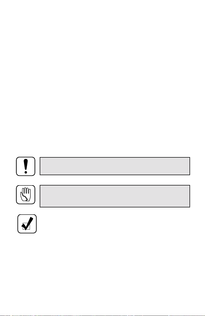
Model AT 542 Transmission — Left-Front View
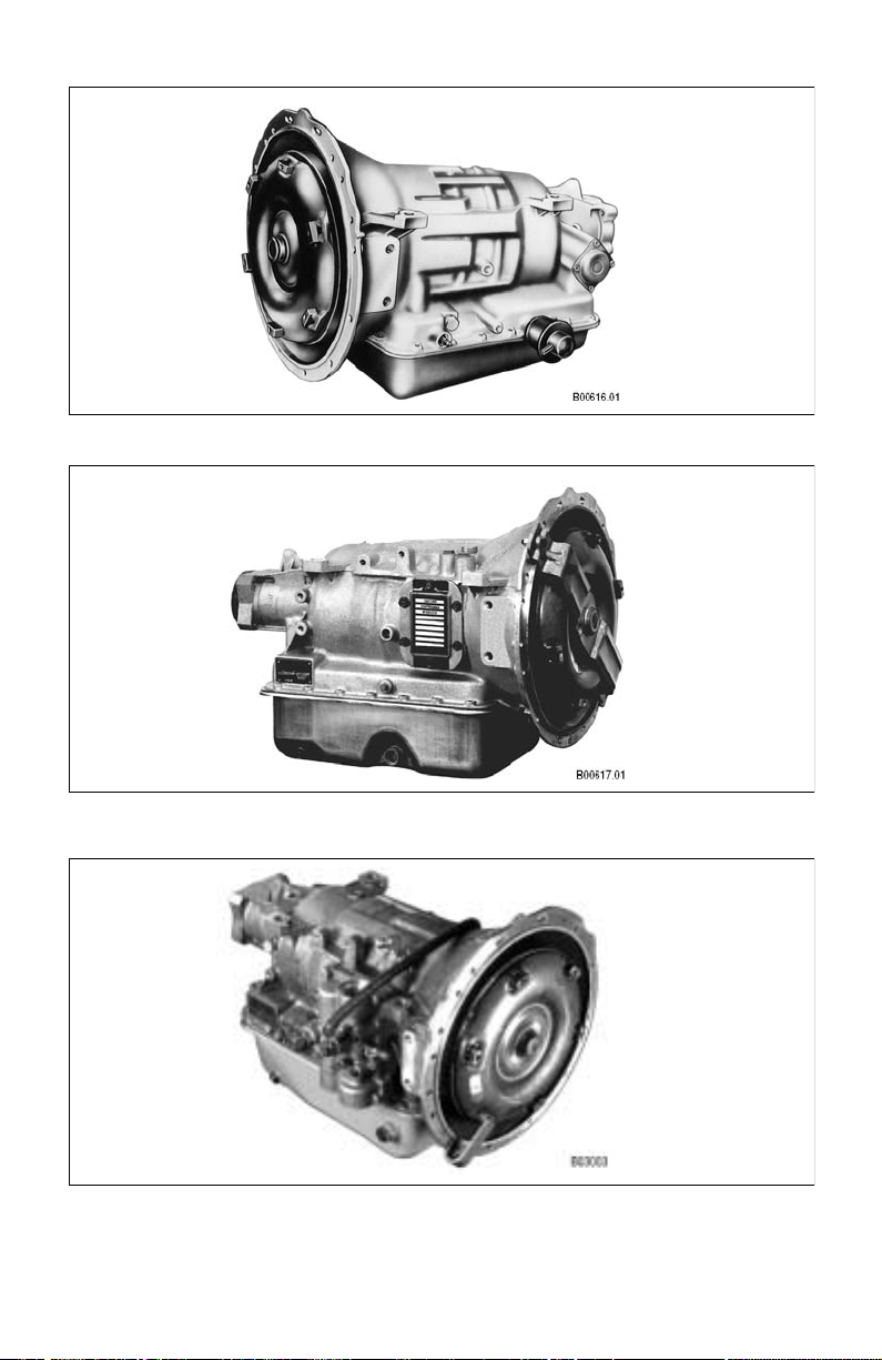
Model AT 545 Transmission — Right-Front View
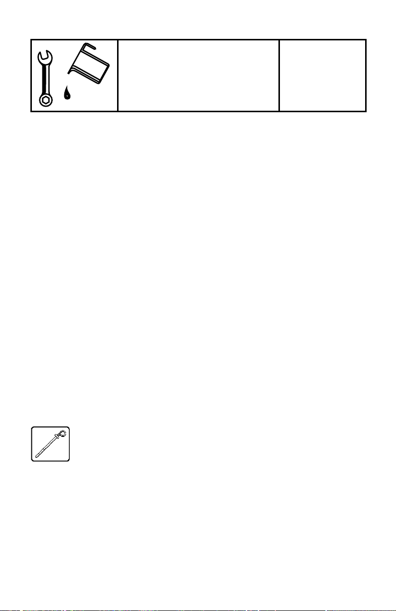
Model AT 545R Transmission — Right-Front View
PREVENTIVE
S
ECTION
MAINTENANCE
I
1–1. PERIODIC INSPECTION AND CARE
Clean and inspect the exterior of the transmission at regular intervals. The severity
of service and operating conditions will determine the frequency of such
inspections. Inspect the transmission for the following items:
•
Loose bolts (transmission and mounting components)
•
Fluid leaks (correct immediately)
•
Shift linkage freely positioned by transmission detent
•
Full (and ease of) movement of mechanical modulator linkage
•
Vacuum leaks in the air line and modulator
•
Damaged or loose fluid lines
•
Worn or frayed electrical connections
•
Worn, out-of-phase driveline U-joints and slip fittings
•
Loose or missing speedometer cable fittings
•
Damaged PTO linkage and driveline
Check transmission fluid regularly . Once consistent daily hot le vel checks ha ve been
established, and daily inspection shows no sign of transmission leakage, less
frequent checks can be made.
1–2. IMPORTANCE OF PROPER FLUID LEVEL
Because the transmission fluid cools, lubricates, and transmits hydraulic
power, it is important that the proper fluid le v el be maintained at all times.
If the fluid level is too low, the converter and clutches will not receive an
adequate supply of fluid. If the level is too high, the fluid will aerate, the
transmission will overheat, and fluid may be expelled through the breather
or dipstick tube.
1–3. DIPSTICK MARKINGS
Earlier models use a dipstick marked FULL and ADD (Figure 1–1). Later models
use a dipstick marked COLD RUN and HOT RUN. Figure 1–2 illustrates the marks
in relation to the transmission.
1
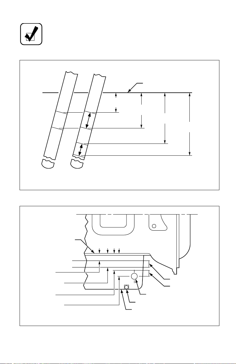
NOTE:
The ADD and FULL dimensions on earlier dipsticks coincide
with the HOT RUN band dimensions on later dipsticks.
TRANS
HOT
FULL
ADD
EARLIER
MODELS
MODELS
TOP OF OIL PAN
EARLIER
MODELS
FULL
0.50 in.
ADD
(12.7 mm)
1.00 in.
(25.4 mm)
1.50 in.
(38.1 mm)
1.80 in.
(45.7 mm)
IN
NEUTRAL
®
OIL
TOP OF OIL PAN
0.50 in.
CHECK IN NEUTRAL
HOT
COLD
RUN
AT IDLE
USE DEXRON
RUN
(12.7 mm)
1.00 in.
(25.4 mm)
(38.1 mm)
NOTE: This illustration is not a template,
placement of markings will vary according
LATER
to the installation angle of the dipstick tube.
Figure 1–1. Typical Dipstick Markings
FILL TUBE ADAPTER HOLE
DRAIN PLUG
OIL PAN
1.50 in.
1.80 in.
(45.7 mm)
V03004
LATER
MODELS
HOT RUN
COLD RUN
V03005
Figure 1–2. How Fluid Levels Are Established
2
•
•
•
1–4. FLUID CHECK PROCEDURE
WARNING: When checking the fluid level, be sure the transmission
is in N ( Neutral) or P ( Park), parking brake and/or emergency brakes
are set and properly engaged, and the wheels are chocked.
Unexpected and possible sudden vehicle movement may occur if
these precautions are not taken.
CAUTION : Dirt and foreign matter must not be permitted to enter
the fluid system. It can cause valves to stick, cause undue wear of
transmission parts, or clog passages.
Always check the fluid level a minimum of two times. Consistency is important in
maintaining accuracy. If inconsistent readings persist, check the transmission
breather and the vent hole in the dipstick fill tube to ensure they are clean and free of
debris. The vent hole is located on the underside of the fill tube just below the seal of
the dipstick cap.
Check the fluid level by the following procedures and record any abnormal fluid
level, milky appearance, or any trace of coolant in the fluid on your maintenance
records. Refer to Paragraph 1–8.
a.
Cold Check
NOTE: The only purpose of the Cold Check is to determine if the
transmission has enough fluid to be safely operated until a Hot Check
can be made.
Park the vehicle on a level surface, set the parking brake and/or emergency
brakes, and chock the vehicle wheels.
Run the engine at 1000–1500 rpm for one minute to purge air from the
system. Return engine to idle, then shift to D (Drive) and then to R (Reverse)
to fill the hydraulic circuits with fluid. Then, shift to N (Neutral) or P (Park)
and allow the engine to idle (500–800 rpm). The sump temperature should be
between 60–120°F (16–49°C).
CAUTION : The fluid level rises as sump temperature increases. DO
NOT fill above the COLD RUN band if the transmission fluid is
below normal operating temperature.
Clean around the end of the fill tube before removing the dipstick. Wipe the
dipstick clean and check the fluid level. If the fluid on the dipstick is within
the COLD RUN band, the level is satisfactory for operating the transmission
3
•
•
•
•
until the fluid is hot enough to perform a HOT R UN check. If the fluid le v el is
not within the COLD RUN band, add or drain fluid as necessary to bring the
level to the middle of the COLD RUN band.
Perform a hot check at the first opportunity after the normal operating sump
temperature 160–200°F (71–93°C) is reached.
b.
Hot Check
NOTE: The fluid level rises as the temperature increases. To ensure
an accurate check, operate the transmission until the sump fluid
temperature is 160–200°F (71–93°C); converter-out temperature is
180–220°F (82–104°C).
Park the vehicle on a lev el surface and shift to N (Neutral) or P (Park). Set the
parking brake and/or emergency brakes and chock the vehicle wheels. Allow
the engine to idle (500–800 rpm).
Wipe the dipstick clean and check the fluid level. The safe operating range is
any level within the HOT RUN band on the dipstick. If the level is not within
this band, add or drain fluid as necessary to bring the level to the top of the
HOT RUN band. Approximately 1 quart (1 liter) of fluid is required to raise
the level from the bottom to the top of the band.
1–5. KEEPING FLUID CLEAN
˙
It is absolutely necessary that the fluid put into the transmission be clean. Fluid
must be handled in clean containers, fillers, etc., to prevent foreign material from
entering the transmission. Lay dipstick in a clean place while filling the
transmission.
CAUTION : Containers or fillers that have been used to handle any
antifreeze or engine coolant solution must not be used for
transmission fluid. Antifreeze and coolant solutions contain ethylene
glycol which, if introduced into the transmission, can cause the clutch
plates to fail.
1–6. RECOMMENDED AUTOMATIC TRANSMISSION FLUID
AND VISCOSITY GRADE
Hydraulic fluids (oils) used in the transmission are important influences on
transmission performance, reliability, and durability. DEXRON
recommended for on-highway applications. T ype C-4 fluids are recommended
for severe duty and off-highway applications.
4
®
-III fluids are
•
•
P
Some DEXRON
®
fluids are also qualified as Type C-4 fluids. To ensure the
fluid is qualified for use in Allison transmissions, check for a DEXRON
C-4 fluid license, or approval numbers on the container, or consult the
lubricant manufacturer. Consult your Allison Transmission dealer or
distributor before using other fluid types; fluid types such as Type F and
universal farm fluids may or may not be properly qualified for use in your
Allison transmission.
CAUTION : Disregarding minimum fluid temperature limits can
result in transmission malfunction or reduced transmission life.
When choosing the optimum viscosity grade of fluid to use, duty cycle,
preheat capabilities, and/or geographical location must be taken into
consideration. Table 1–1 lists the minimum fluid temperatures at which the
transmission may be safely operated. Preheat with auxiliary heating
equipment or by running the vehicle with the transmission in N (Neutral) or
(Park) for a minimum of 20 minutes before attempting range operation.
Table 1–1. Transmission Fluid Operating Temperature Requirements
Viscosity Grade
Ambient T emperatur e Below Which Preheat
Is Required
Fahrenheit Celsius
®
or
SAE 0W-20 (Arctic) –31 –35
DEXRON
®
-III
–22 –30
SAE 10W –4 –20
SAE 15W-40 5 –15
SAE 30 32 0
SAE 40 50 10
1–7. FLUID AND FILTER CHANGE INTERVALS
Fluid and filter change frequency is determined by severity of
transmission service and by the filter equipment installed. Table 1–2 is a
general guide. More frequent changes may be required when operations
are subject to high levels of contamination or ov erheating.
5

6
•
•
•
Table 1–2. Fluid and Filter Change Intervals
AT
Transmission
On-Highway,
Light-Duty
Fluid Change Internal Sump
Paper Filter:
25,000 miles
(40 000 km)
or 12 months*
Brass Filter :
50,000 miles
(80 000 km)
Paper Filter: at
each fluid change
interval
Brass Filter:
50,000 miles
(80 000 km) with
no time limit
External Auxiliary
Filters**
After first 5000
miles (8 000 km)
and at 25,000 miles
(40 000 km)
or 12 months,
thereafter*
or 24 months*
On-Highway,
Heavy-Duty,
Retarder
Paper or Brass
Filter: 25,000
miles (40 000 km)
or 12 months*
Paper Filter: at
each fluid change
interval
Brass Filter:
50,000 miles
After first 5000
miles (8 000 km)
and at normal fluid
change intervals,
thereafter*
(80 000 km) with
no time limit
Off-Highway
Paper or Brass
Filter : 1000 hours
max or 12 months*
Paper or Brass
Filter: at each fluid
change interval
After first 500 hours,
and at normal fluid
change intervals
thereafter*
* Whichever occurs first.
**
When an Allison high-efficiency filter is used, the change interval is until the Change Filter light
indicates the filter is contaminated or until it has been in use for three years, whichever occurs first.
No mileage restrictions apply.
A brass screen sump filter is available for all AT 500 and AT 1500 Series
transmissions for both the shallow pan and the deep pan models. To convert an
AT deep pan 5.3 inches (135 mm) with paper filter to the brass screen filter
configuration, a service conversion kit is required. Refer to Service Information
Letter (SIL) 5-TR-93 (latest revision).
1–8. FLUID AND FILTER CHANGE PROCEDURE
a. Drain
The transmission should be at operating temperature to assist
draining.
Remove the drain plug from the pan. Disconnect the fill tube from the pan
only if required.
Examine the drained fluid for evidence of contamination (refer to Paragraph 1–9).
•
•
•
•
•
•
•
•
Remove the pan and filter. Discard the pan gasket, filter, and filter tube
sealring. Clean the pan.
Remove, clean, and reinstall the governor feed line screen in the control
valve body.
For models with the shallow pan (3.8 inch, 97 mm), insert a new sealring into
the filter tube. Install the filter tube into the main housing. Install a new brass
screen sump filter onto the filter tube. Bolt the filter onto the transmission.
Replace the pan gasket and reattach the pan (reference Transmission Service
Manual). Tighten the pan screws to 10–15 lb ft (14–20 N·m).
NOTE: To prevent leakage, pan washer-head screws must retain a
5 lb ft (7 N·m) minimum torque after gasket sets.
Install the drain plug into the pan and tighten it to 15–20 lb ft (20–27 N·m). If
removed, install the fill tube and tighten the fill tube fitting in the pan boss to
65–75 lb ft (88–102 N·m).
For models with the deep pan (5.3 inch, 135 mm), insert a new sealring into
the filter tube. Install the filter tube into the main housing. When converting
from paper filter to brass screen filter, and for servicing the pan with the brass
screen filter, attach filter bracket (see SIL 5-TR-93). Install the brass screen
sump filter onto the filter tube. Bolt the filter to the filter bracket. Replace the
pan gasket and reattach the pan (reference Transmission Service Manual).
Tighten the pan screws to 10–15 lb ft (14–20 N·m).
•
•
NOTE: To prevent leakage, pan washer-head screws must retain a
5 lb ft (7 N·m) minimum torque after gasket sets.
Install the drain plug into the pan and tighten it to 15–20 lb ft (20–27 N·m). If
removed, install the fill tube and tighten the fill tube fitting in the pan boss to
65–75 lb ft (88–102 N·m).
If an external auxiliary filter is present, replace the filter element. Refer to
Table 1–2 for replacement intervals.
b.
Fill
Refill the transmission. (Refer to Paragraph 1–6, and to Table 1–3.)
The refill amount is less than the initial fill because some of the fluid remains
in the external circuits and transmission cavities.
Check the fluid level as outlined in Paragraph 1–4.
7
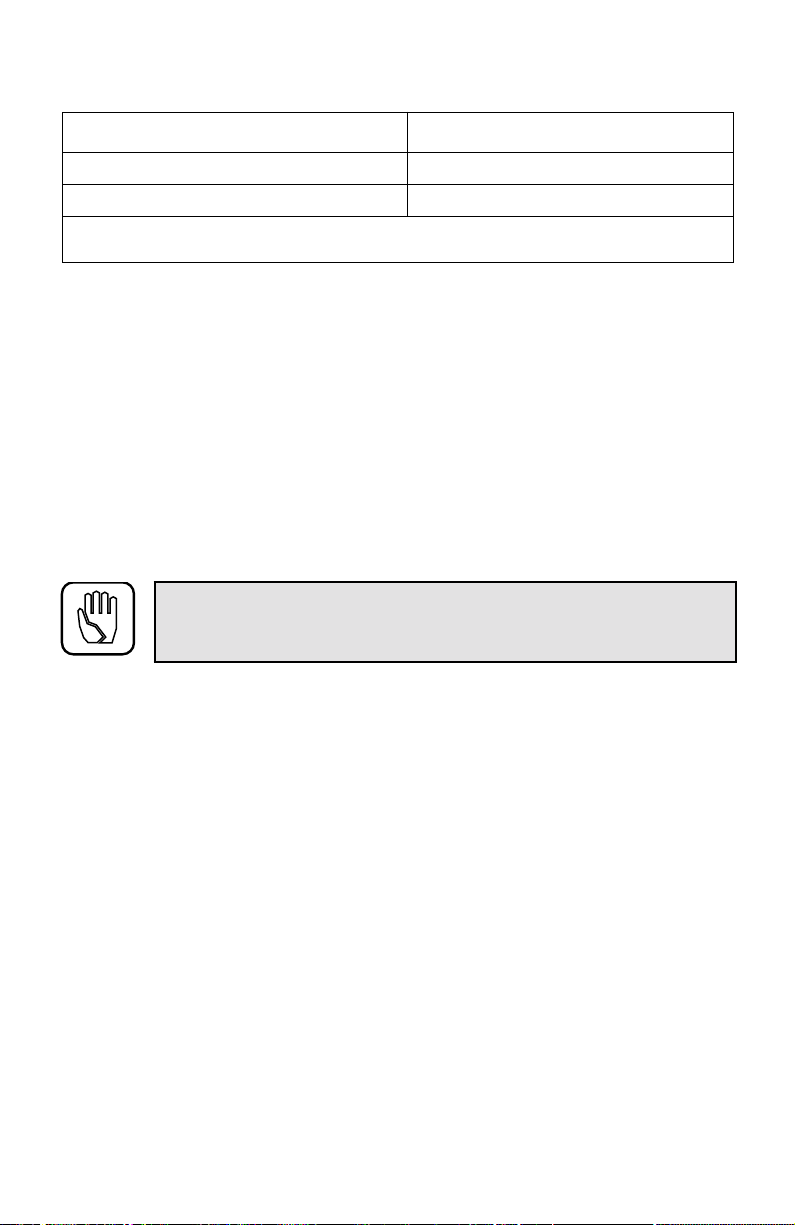
Table 1–3. Transmission Fluid Refill Capacities
Pan T ype Quantity
Shallow pan — 3.8 inches (97 mm) 9 U.S. qt. (8.5 liters)*
Deep pan — 5.3 inches (135 mm) 16 U.S. qt. (15 liters)*
* The amount of transmission fluid shown in the following chart does not include the
amount required to fill the external circuits.
1–9. FLUID CONTAMINATION
Examine at Fluid Change
a.
At each fluid change, examine the fluid which is drained for evidence of dirt or
engine coolant (water). A normal amount of condensation will emulsify in the fluid
during operation of the transmission. However, if there is evidence of coolant, check
the cooler (heat exchanger) for leakage between the cooler and fluid areas. Fluid in
the coolant side of the cooler (heat exchanger) is another sign of leakage. This,
however, may indicate leakage from the engine oil system.
b.
Metal Particles
8
CAUTION:
If excessive metal contamination has occurred,
replacement of the cooler and replacement of all bearings within the
transmission is recommended.
Metal particles in the fluid (except for the minute particles normally trapped in the
filter) indicate damage has occurred in the transmission. When these particles are
found in the sump, the transmission may need to be disassembled and closely
inspected to find the source. Metal contamination requires complete disassembly of
the transmission and cleaning of all internal and external circuits, cooler, and all
other areas where the particles could lodge. (Refer to Paragraph 1–10, Auxiliary
Filter.)
c.
Coolant Leakage
If engine coolant leaks into the transmission hydraulic system, take immediate
action to prevent malfunction and possible serious damage. Completely
disassemble, inspect, and clean the transmission. Remove all traces of the coolant
and varnish deposits resulting from coolant contamination. Replace friction clutch
plates contaminated with ethylene glycol.
d.
Fluid Analysis
Transmission protection and fluid change intervals can be optimized by monitoring
oxidation according to the tests and limits shown in Table 1–4. Consult your local
telephone directory for fluid analysis firms. Use one fluid analysis firm as results
from various firms cannot be accurately compared. Refer to the Technicians’ Guide
for Automatic Transmission Fluid (GN2055EN) for additional information.
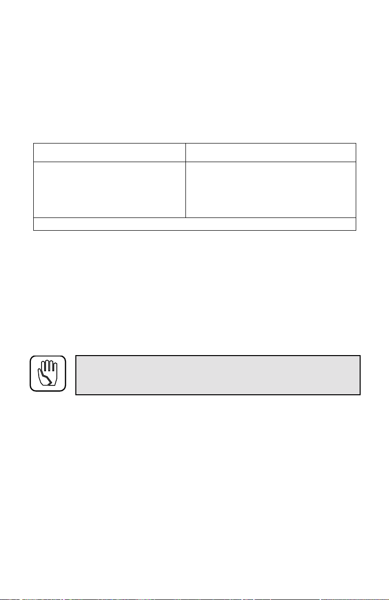
Table 1–4. Fluid Oxidation Measurement Limits
Measurement Limit
Viscosity
Carbonyl absorbance
Total acid number
Solids
A =
*
Absorbance units.
±25% change from new fluid
+0.3 A*/0.1 mm change from new fluid
+3.0 change from new fluid
2% by volume maximum
1–10. AUXILIARY FILTER
If a condition occurs that introduces debris into the transmission hydraulic system, a
complete cleanup of the cooler and lines is recommended.
Because repeated cleaning and flushing may not remove all debris, installation of an
auxiliary filter in the cooler-out line (between cooler and transmission) is
recommended. This recommendation applies whether the transmission is
overhauled or replaced by a new or rebuilt unit.
CAUTION:
DO NOT install an auxiliary filter in the AT 500R
primary cooler circuit. This reduces retarder effectiveness. An
auxiliary filter in the secondary cooler circuit is sufficient.
If any doubt exists about the cleanup of the cooler, replace the cooler.
The auxiliary filter should have at least a 40-micron filter element or finer and a
maximum filter pressure drop of 3 psi (21 kPa) at 4.5 gpm (17 liters/minute) at
180˚F (82˚C). The maximum external circuit pressure drop must not exceed 35 psi
(241 kPa) at 4.5 gpm (17 liters/minute) at operating temperature, in N (Neutral), and
at 2400 rpm.
9
 Loading...