


 Loading...
3000 AND300040 PROANDUCT4000FAMILIESPRODUCTTROUBLESHOOTINGFAMILIES TROUBLESHOOTINGMANUAL—ALLISON 4MANUALth GENERATION– CONTROLS
ALLISON 4TH GENERATION CONTROLS
DIAGNOSTIC TROUBLE CODES (DTC) |
PREFACE |
|
|
|
|
Welcome to the TS3989EN Troubleshooting Manual. We make every effort to keep our service information current and accurate. Because of the time lag involved with writing and printing processes, the transmission TCM may report a code that has not yet been added to this document. If you encounter a code that is not yet in this publication, please call Allison Transmission.
Go to the Table of Contents
Copyright © 2008 Allison Transmission, Inc.

Troubleshooting
Manual
2008 OCTOBER
TS3989EN
Allison Transmission
VOCATIONAL MODELS
3000 VOCATIONAL MODELS
3000 |
HS |
3500 |
RDS |
B 300(P)(R) |
3000 |
RDS |
3500 |
EVS |
B 400(P)(R) |
3000 |
EVS |
|
|
T 200 |
3000 MH |
|
|
T 300 |
|
3000 |
PTS |
|
|
|
3000 TRV |
|
|
|
|
3200 |
SP |
3500 |
SP |
3700 SP |
3200 TRV |
|
|
|
|
4000 VOCATIONAL MODELS
4000 EVS |
4500 EVS |
4700 EVS |
4800 EVS |
B 500 |
4000 HS |
4500 HS |
4700 RDS |
|
B 500P |
4000 MH |
4500 RDS |
4700 OFS |
|
B 500R |
4000 RDS |
4500 SP |
|
|
B 500PR |
4000 TRV |
4500 TRV |
|
|
T 425 |
|
|
|
|
T 450 |
Allison Transmission, Inc.
P.O. Box 894 Indianapolis, Indiana 46206-0894
www.allisontransmission.com
Printed in USA |
Copyright © 2008 Allison Transmission, Inc. |

3000 AND 4000 PRODUCT FAMILIES TROUBLESHOOTING MANUAL—ALLISON 4th GENERATION CONTROLS
FOREWORD — How to Use This Manual
This manual provides troubleshooting information for the 3000 and 4000 Product Families Transmissions. Service Manuals SM4013EN and SM4014EN, plus Parts Catalogs PC2150EN and PC2456EN may be used in conjunction with this manual.
This manual includes:
•Description of the 3000 and 4000 Product Families Allison 4TH Generation Electronic Control system.
•Description of the electronic control system components.
•Description of diagnostic codes, system responses to faults, and troubleshooting.
•Wire, terminal, and connector repair information.
Specific instructions for using many of the available or required service tools and equipment are not included in this manual. The service tool manufacturer will furnish instructions for using the tools or equipment.
Additional information may be published from time to time in Service Information Letters (SIL) and will be included in future revisions of this and other manuals. Please use these SILs to obtain up-to-date information concerning Allison Transmission products.
This publication is revised periodically to include improvements, new models, special tools, and procedures. A revision is indicated by a new date on the title page and in the lower left corner of the rear cover. Check with your Allison Transmission service outlet for the currently applicable publication. Additional copies of this publication may be purchased from authorized Allison Transmission service outlets. Look in your telephone directory under the heading of Transmissions — Truck, Tractor, etc.
Take time to review the Table of Contents and the manual. Reviewing the Table of Contents will aid you in quickly locating information.
NOTE: Allison Transmission is providing for service of wiring harnesses and wiring harness components as follows:
•Repair parts for the internal wiring harness and for wiring harness components attached to the shift selector will be available through the Allison Transmission Parts Distribution Center (PDC). Use the P/N from your appropriate parts catalog or from Appendix E in this manual. Allison Transmission (AT) is responsible for warranty on these parts.
•Repair parts for the external harnesses and external harness components must be obtained from St. Clair Technologies Inc. (SCTI). SCTI provides parts to any Allison customer or OEM and is responsible for warranty on these parts. SCTI recognizes AT, manufacturers, and SCTI part numbers. SCTI provides a technical HELPLINE at 519-627-1673 (Wallaceburg). SCTI will have parts catalogs available. The SCTI addresses and phone numbers for parts outlets are:
St. Clair Technologies, Inc. |
St. Clair Technologies, Inc. |
920 Old Glass Road |
Calle Damanti S/N Col |
Wallaceburg, Ontario, N8A 4L8 |
Guadalupe—Guaymas |
Phone: 519-627-1673 |
Sonora, Mexico 85440 |
Fax: 519-627-4227 |
Phone: 011-526-2222-43834 |
|
Fax: 011-526 2222-43553 |
ii |
Copyright © 2008 Allison Transmission, Inc. |

3000/4000 PRODUCT FAMILIES 4TH GENERATION ELECTRONIC CONTROLS TROUBLESHOOTING MANUAL
IMPORTANT SAFETY NOTICE
IT IS YOUR RESPONSIBILITY to be completely familiar with the warnings and cautions used in this manual. These warnings and cautions advise against using specific service procedures that can result in personal injury, equipment damage, or cause the equipment to become unsafe. These warnings and cautions are not exhaustive. Allison Transmission could not possibly know, evaluate, or advise the service trade of all conceivable procedures by which service might be performed or of the possible hazardous consequences of each procedure. Consequently, Allison Transmission has not undertaken any such broad evaluation. Accordingly, ANYONE WHO USES A SERVICE PROCEDURE OR TOOL WHICH IS NOT RECOMMENDED BY ALLISON TRANSMISSION MUST first be thoroughly satisfied that neither personal safety nor equipment safety will be jeopardized by the service procedures used.
Also, be sure to review and observe WARNINGS, CAUTIONS, and NOTES provided by the vehicle manufacturer and/or body builder before servicing the Allison transmission in that vehicle.
Proper service and repair is important to the safe and reliable operation of the equipment. The service procedures recommended by Allison Transmission and described in this manual are effective methods for performing troubleshooting operations. Some procedures require using specially designed tools. Use special tools when and in the manner recommended.
The WARNINGS, CAUTIONS, and NOTES in this manual apply only to the Allison transmission and not to other vehicle systems which may interact with the transmission. Be sure to review and observe any vehicle system information provided by the vehicle manufacturer and/or body builder at all times the Allison transmission is being serviced.
WARNINGS, CAUTIONS, AND NOTES
Three types of headings are used in this manual to attract your attention:
WARNING! |
Is used when an operating procedure, practice, etc., which, if not correctly followed, |
|
could result in injury or loss of life. |
||
|
||
|
|
|
CAUTION: |
Is used when an operating procedure, practice, etc., which, if not strictly observed, |
|
could result in damage to or destruction of equipment. |
|
|
|
|
|
|
|
NOTE: Is used when an operating procedure, practice, etc., is essential to highlight. |
||
Copyright © 2008 Allison Transmission, Inc. |
iii |

3000 AND 4000 PRODUCT FAMILIES TROUBLESHOOTING MANUAL—ALLISON 4th GENERATION CONTROLS
TRADEMARKS USED IN THIS MANUAL
The following trademarks are the property of the companies indicated:
•Allison DOCTM is a trademark of General Motors Corporation.
•DEXRON® is a registered trademark of General Motors Corporation.
•LPS® Cleaner is a registered trademark of LPS Laboratories.
•Loctite® is a registered trademark of the Loctite Corporation.
•MagiKey® is a registered trademark of NEXIQ Technologies, Inc.
•Teflon® is a registered trademark of the DuPont Corporation.
•TranSyndTM is a trademark of Castrol Ltd.
SHIFT SELECTOR TERMS AND DISPLAY INDICATIONS
Shift selector terms and displays are represented in this manual as follows:
•Button Names — ↑, ↓, “display mode”, MODE, etc.
•Transmission Ranges — D (Drive), N (Neutral), R (Reverse), 1 (First), 2 (Second), etc.
•Displays — “o, L”; “o, K”, etc. (Display occurs one character at a time.)
iv |
Copyright © 2008 Allison Transmission, Inc. |

3000 AND 4000 PRODUCT FAMILIES TROUBLESHOOTING MANUAL—ALLISON 4th GENERATION CONTROLS
TABLE OF CONTENTS
Page
FOREWARD. . . . . . . . . . . . . . . . . . . . . . . . . . . . . . . . . . . . . . . . . . . . . . . . . . . . . . . . . . . . . . . . . . . . . . . . . . .ii IMPORTANT SAFETY NOTICE . . . . . . . . . . . . . . . . . . . . . . . . . . . . . . . . . . . . . . . . . . . . . . . . . . . . . . . . . iii WARNINGS, CAUTIONS, AND NOTES . . . . . . . . . . . . . . . . . . . . . . . . . . . . . . . . . . . . . . . . . . . . . . . . . . . iii TRADEMARKS USED IN THIS MANUAL . . . . . . . . . . . . . . . . . . . . . . . . . . . . . . . . . . . . . . . . . . . . . . . . iv SHIFT SELECTOR TERMS AND DISPLAY INDICATIONS. . . . . . . . . . . . . . . . . . . . . . . . . . . . . . . . . . . iv
SECTION 1. GENERAL DESCRIPTION
1–1. TRANSMISSION . . . . . . . . . . . . . . . . . . . . . . . . . . . . . . . . . . . . . . . . . . . . . . . . . . . . . . . . . . . . . . . 1–1 1–2. TRANSMISSION CONTROL MODULE (TCM) . . . . . . . . . . . . . . . . . . . . . . . . . . . . . . . . . . . . . . 1–3 1–3. SHIFT SELECTOR . . . . . . . . . . . . . . . . . . . . . . . . . . . . . . . . . . . . . . . . . . . . . . . . . . . . . . . . . . . . . . 1–4 A. Pushbutton Shift Selector . . . . . . . . . . . . . . . . . . . . . . . . . . . . . . . . . . . . . . . . . . . . . . . . . . . . . . . 1–4 B. Lever Shift Selector . . . . . . . . . . . . . . . . . . . . . . . . . . . . . . . . . . . . . . . . . . . . . . . . . . . . . . . . . . . 1–5
1–4. THROTTLE POSITION SENSOR . . . . . . . . . . . . . . . . . . . . . . . . . . . . . . . . . . . . . . . . . . . . . . . . . . 1–6 1–5. SPEED SENSORS. . . . . . . . . . . . . . . . . . . . . . . . . . . . . . . . . . . . . . . . . . . . . . . . . . . . . . . . . . . . . . . 1–7 1–6. CONTROL MODULE. . . . . . . . . . . . . . . . . . . . . . . . . . . . . . . . . . . . . . . . . . . . . . . . . . . . . . . . . . . . 1–8 1–7. WIRING HARNESSES. . . . . . . . . . . . . . . . . . . . . . . . . . . . . . . . . . . . . . . . . . . . . . . . . . . . . . . . . . 1–12 A. External Wiring Harness. . . . . . . . . . . . . . . . . . . . . . . . . . . . . . . . . . . . . . . . . . . . . . . . . . . . . . . 1–12 B. Internal Wiring Harness . . . . . . . . . . . . . . . . . . . . . . . . . . . . . . . . . . . . . . . . . . . . . . . . . . . . . . . 1–14
1–8. VEHICLE INTERFACE MODULE . . . . . . . . . . . . . . . . . . . . . . . . . . . . . . . . . . . . . . . . . . . . . . . . 1–16 1–9. AUTODETECT FEATURE. . . . . . . . . . . . . . . . . . . . . . . . . . . . . . . . . . . . . . . . . . . . . . . . . . . . . . . 1–16 A. Retarder . . . . . . . . . . . . . . . . . . . . . . . . . . . . . . . . . . . . . . . . . . . . . . . . . . . . . . . . . . . . . . . . . . . 1–17 B. Oil Level Sensor (OLS) . . . . . . . . . . . . . . . . . . . . . . . . . . . . . . . . . . . . . . . . . . . . . . . . . . . . . . . 1–17 C. Throttle Source . . . . . . . . . . . . . . . . . . . . . . . . . . . . . . . . . . . . . . . . . . . . . . . . . . . . . . . . . . . . . . 1–17 D. Engine Coolant Temperature . . . . . . . . . . . . . . . . . . . . . . . . . . . . . . . . . . . . . . . . . . . . . . . . . . . 1–18
1–10. TRANSID (TID) . . . . . . . . . . . . . . . . . . . . . . . . . . . . . . . . . . . . . . . . . . . . . . . . . . . . . . . . . . . . . . . 1–18 1–11. SPECIAL ELECTRONIC/ELECTRICAL TOOLS . . . . . . . . . . . . . . . . . . . . . . . . . . . . . . . . . . . . 1–19
SECTION 2. DEFINITIONS AND ABBREVIATIONS
2–1. CHECK TRANS LIGHT . . . . . . . . . . . . . . . . . . . . . . . . . . . . . . . . . . . . . . . . . . . . . . . . . . . . . . . . . . 2–1 2–2. ALLISON TRANSMISSION DIAGNOSTIC TOOL. . . . . . . . . . . . . . . . . . . . . . . . . . . . . . . . . . . . 2–5 2–3. ABBREVIATIONS . . . . . . . . . . . . . . . . . . . . . . . . . . . . . . . . . . . . . . . . . . . . . . . . . . . . . . . . . . . . . . 2–7
Copyright © 2008 Allison Transmission, Inc. |
v |

3000 AND 4000 PRODUCT FAMILIES TROUBLESHOOTING MANUAL—ALLISON 4th GENERATION CONTROLS
TABLE OF CONTENTS (cont’d)
Page
SECTION 3. BASIC KNOWLEDGE
3–1. BASIC KNOWLEDGE REQUIRED. . . . . . . . . . . . . . . . . . . . . . . . . . . . . . . . . . . . . . . . . . . . . . . . 3–1 3–2. USING THE TROUBLESHOOTING MANUAL. . . . . . . . . . . . . . . . . . . . . . . . . . . . . . . . . . . . . . 3–1 3–3. SYSTEM OVERVIEW . . . . . . . . . . . . . . . . . . . . . . . . . . . . . . . . . . . . . . . . . . . . . . . . . . . . . . . . . . 3–2 3–4. IMPORTANT INFORMATION IN THE TROUBLESHOOTING PROCESS. . . . . . . . . . . . . . . . 3–2 3–5. BEGINNING THE TROUBLESHOOTING PROCESS. . . . . . . . . . . . . . . . . . . . . . . . . . . . . . . . . 3–4 3–6. TCM DIAGNOSTIC PROCEDURE . . . . . . . . . . . . . . . . . . . . . . . . . . . . . . . . . . . . . . . . . . . . . . . . 3–5 3–7. RESTTING OF TCM PARAMETERS TO SUPPORT ENGINE UPDATE . . . . . . . . . . . . . . . . . . 3–6 3–8. RESETTING TCM AUTOSELECT . . . . . . . . . . . . . . . . . . . . . . . . . . . . . . . . . . . . . . . . . . . . . . . . 3–6 3–9. HYDRAULIC OPERATION DURING ELECTRICAL INTERRUPTION. . . . . . . . . . . . . . . . . . 3–6
SECTION 4. WIRE CHECK PROCEDURES
4–1. TESTING FOR OPENS, SHORTS BETWEEN WIRES, AND SHORTS-TO-GROUND. . . . . . . 4–1
4–2. TESTING AT TRANSMISSION FEEDTHROUGH CONNECTOR FOR INTERNAL
HARNESS OPENS, SHORTS BETWEEN WIRES, AND SHORTS-TO-GROUND . . . . . . . . . . 4–3
SECTION 5. FLUID CHECK PROCEDURES
5–1. OIL LEVEL SENSOR (OLS) INTRODUCTION . . . . . . . . . . . . . . . . . . . . . . . . . . . . . . . . . . . . . . 5–1 5–2. ELECTRONIC FLUID LEVEL READING (SHIFT SELECTOR) . . . . . . . . . . . . . . . . . . . . . . . . 5–3 A. Fluid Level Reading Procedure. . . . . . . . . . . . . . . . . . . . . . . . . . . . . . . . . . . . . . . . . . . . . . . . . . 5–3 5–3. ELECTRONIC FLUID LEVEL CHECK (ALLISON DOC™ FOR PC–SERVICE TOOL) . . . . . 5–5 A. Fluid Level Check Procedure . . . . . . . . . . . . . . . . . . . . . . . . . . . . . . . . . . . . . . . . . . . . . . . . . . . 5–5
5–4. COLD CHECK. . . . . . . . . . . . . . . . . . . . . . . . . . . . . . . . . . . . . . . . . . . . . . . . . . . . . . . . . . . . . . . . . 5–6 A. Purpose . . . . . . . . . . . . . . . . . . . . . . . . . . . . . . . . . . . . . . . . . . . . . . . . . . . . . . . . . . . . . . . . . . . . 5–6 B. Cold Check Procedure . . . . . . . . . . . . . . . . . . . . . . . . . . . . . . . . . . . . . . . . . . . . . . . . . . . . . . . . . 5–6
5–5 HOT CHECK . . . . . . . . . . . . . . . . . . . . . . . . . . . . . . . . . . . . . . . . . . . . . . . . . . . . . . . . . . . . . . . . . . 5–7 A. Hot Check Procedure. . . . . . . . . . . . . . . . . . . . . . . . . . . . . . . . . . . . . . . . . . . . . . . . . . . . . . . . . . 5–7 5–6 KEEPING FLUID CLEAN . . . . . . . . . . . . . . . . . . . . . . . . . . . . . . . . . . . . . . . . . . . . . . . . . . . . . . . 5–8 A. Foreign Material . . . . . . . . . . . . . . . . . . . . . . . . . . . . . . . . . . . . . . . . . . . . . . . . . . . . . . . . . . . . . 5–8
5–7 FLUID RECOMMENDATIONS . . . . . . . . . . . . . . . . . . . . . . . . . . . . . . . . . . . . . . . . . . . . . . . . . . . 5–8
vi |
Copyright © 2008 Allison Transmission, Inc. |

3000 AND 4000 PRODUCT FAMILIES TROUBLESHOOTING MANUAL—ALLISON 4th GENERATION CONTROLS
TABLE OF CONTENTS (cont’d)
Page
SECTION 6.DIAGNOSTIC TROUBLE CODES (DTC)
6–1. DIAGNOSTIC CODE MEMORY. . . . . . . . . . . . . . . . . . . . . . . . . . . . . . . . . . . . . . . . . . . . . . . . . . . 6–1 6–2. CODE READING AND CODE CLEARING. . . . . . . . . . . . . . . . . . . . . . . . . . . . . . . . . . . . . . . . . . 6–2 6–3. DIAGNOSTIC CODE RESPONSE . . . . . . . . . . . . . . . . . . . . . . . . . . . . . . . . . . . . . . . . . . . . . . . . . 6–3 6–4. SHIFT SELECTOR DISPLAYS RELATED TO ACTIVE CODES . . . . . . . . . . . . . . . . . . . . . . . . 6–4 6–5. DIAGNOSTIC CODE LIST AND DESCRIPTION . . . . . . . . . . . . . . . . . . . . . . . . . . . . . . . . . . . . . 6–4 6–6. DIAGNOSTIC CODE TROUBLESHOOTING . . . . . . . . . . . . . . . . . . . . . . . . . . . . . . . . . . . . . . . 6–14
A. Beginning the Troubleshooting Process . . . . . . . . . . . . . . . . . . . . . . . . . . . . . . . . . . . . . . . . . . .6–14 B. Solenoid Locations . . . . . . . . . . . . . . . . . . . . . . . . . . . . . . . . . . . . . . . . . . . . . . . . . . . . . . . . . . . 6–14 C. Diagnostic Code Schematics . . . . . . . . . . . . . . . . . . . . . . . . . . . . . . . . . . . . . . . . . . . . . . . . . . . 6–14
SECTION 7. INPUT AND OUTPUT FUNCTIONS
7–1. INPUT FUNCTIONS . . . . . . . . . . . . . . . . . . . . . . . . . . . . . . . . . . . . . . . . . . . . . . . . . . . . . . . . . . . . 7–1 7–2. OUTPUT FUNCTIONS . . . . . . . . . . . . . . . . . . . . . . . . . . . . . . . . . . . . . . . . . . . . . . . . . . . . . . . . . . 7–3
SECTION 8. GENERAL TROUBLESHOOTING OF PERFORMANCE COMPLAINTS
APPENDICES
A. IDENTIFICATION OF POTENTIAL CIRCUIT PROBLEMS . . . . . . . . . . . . . . . . . . . . . . . . . . . A–1 B. MEASURING CLUTCH AND RETARDER PRESSURES . . . . . . . . . . . . . . . . . . . . . . . . . . . . . B–1 C. SOLENOID AND CLUTCH CHART. . . . . . . . . . . . . . . . . . . . . . . . . . . . . . . . . . . . . . . . . . . . . . . C–1 D. WIRE/CONNECTOR CHART . . . . . . . . . . . . . . . . . . . . . . . . . . . . . . . . . . . . . . . . . . . . . . . . . . . . D–1
E.CONNECTOR PART NUMBERS, TERMINAL PART NUMBERS, . . . . . . . . . . . . . . . . . . . . . . .E–1
TOOL PART NUMBERS, AND REPAIR INSTRUCTIONS
F. THROTTLE POSITION SENSOR ADJUSTMENT . . . . . . . . . . . . . . . . . . . . . . . . . . . . . . . . . . . .F–1 G. WELDING ON VEHICLE/VEHICLE INTERFACE MODULE . . . . . . . . . . . . . . . . . . . . . . . . . . G–1 H. HYDRAULIC SCHEMATICS . . . . . . . . . . . . . . . . . . . . . . . . . . . . . . . . . . . . . . . . . . . . . . . . . . . . H–1 J. 3000 AND 4000 PRODUCT FAMILIES WIRING SCHEMATIC. . . . . . . . . . . . . . . . . . . . . . . . . . J–1 K. SOLENOID RESISTANCE CHARTS . . . . . . . . . . . . . . . . . . . . . . . . . . . . . . . . . . . . . . . . . . . . . . K–1 L. EXTERNALLY-GENERATED ELECTRONIC INTERFERENCE. . . . . . . . . . . . . . . . . . . . . . . . .L–1 M. DIAGNOSTIC TREE—3000 AND 4000 PRODUCT FAMILIES HYDRAULIC SYSTEM . . . . M–1 N. ALLISON DOC™ FOR PC–SERVICE TOOL. . . . . . . . . . . . . . . . . . . . . . . . . . . . . . . . . . . . . . . . N–1 P. INPUT/OUTPUT FUNCTIONS . . . . . . . . . . . . . . . . . . . . . . . . . . . . . . . . . . . . . . . . . . . . . . . . . . . .P–1 Q. THERMISTOR TROUBLESHOOTING INFORMATION . . . . . . . . . . . . . . . . . . . . . . . . . . . . . . Q–1 R. SAE J1939 COMMUNICATION LINK . . . . . . . . . . . . . . . . . . . . . . . . . . . . . . . . . . . . . . . . . . . . . R–1
Copyright © 2008 Allison Transmission, Inc. |
vii |

3000 AND 4000 PRODUCT FAMILIES TROUBLESHOOTING MANUAL—ALLISON 4th GENERATION CONTROLS
NOTES
viii |
Copyright © 2008 Allison Transmission, Inc. |
3000 AND 4000 PRODUCT FAMILIES TROUBLESHOOTING MANUAL—ALLISON 4th GENERATION CONTROLS
SECTION 1—GENERAL DESCRIPTION
1–1. TRANSMISSION
The Allison 4th Generation Controls feature closed-loop clutch control to provide superior shift quality over a wide range of operating conditions. The 3000 and 4000 Product Families transmissions configurations can be programmed to have up to six forward ranges, neutral, and one reverse range. The 3700 SP, 4700 RDS, 4700/ 4800 EVS, 4700/4800 SP, and 4700 OFS have up to seven forward ranges and one reverse.
Figure 1–1 is a block diagram of the basic system inputs and outputs.
SHIFT SELECTOR
|
RANGE AND |
|
DISPLAY |
|
|
|
||||||||
|
MODE SWITCH |
|
|
|
|
|||||||||
|
|
|
|
|
|
|
|
|
|
|
|
OIL LEVEL SENSOR |
||
|
SPEED SENSORS |
|
|
|
|
|
|
|
|
|
|
|||
|
|
|
|
|
|
|
|
|
|
|
|
|
||
|
|
|
|
|
|
|
|
|
|
|
|
SOLENOIDS |
||
THROTTLE POSITION SENSOR |
|
|
|
TCM |
|
|
||||||||
|
|
|
|
|
|
|
|
|
|
|||||
|
RETARDER MODULATION |
|
|
|
|
|
DIAGNOSTIC PRESSURE SWITCH |
|
||||||
|
|
|
|
|
|
|
|
|
|
|
||||
|
|
|
|
|
|
|
|
|
|
|
|
|
||
|
|
|
|
|
|
|
|
|
|
|
|
|
|
|
|
VEHICLE/ENGINE |
|
|
|
|
|
|
|
|
|
|
|
|
|
|
|
|
|
|
|
|
|
TEMPERATURE SENSOR |
|
|
||||
|
COMMUNICATION LINKS |
|
|
|
|
|
|
|
|
|
|
|
|
|
|
|
|
|
|
|
(SUMP/RETARDER) |
|
|
||||||
|
|
|
|
|
|
|
|
|
|
|
|
|
|
|
|
|
|
|
|
|
|
|
|
|
|
|
|
|
|
|
|
|
|
|
VIM |
|
|
|
|
|
|
|||
|
|
|
|
|
|
|
|
|
FILTER LIFE |
|
|
|||
|
|
|
|
|
|
|
|
|
|
|
|
SWITCH (PS2) |
|
|
|
|
|
|
|
|
|
|
|
|
|
|
|||
|
|
|
|
|
|
|
|
|
|
|
|
|
|
|
|
|
|
INPUTS |
|
|
OUTPUTS |
|
|
|
V09074.00.00 |
||||
Figure 1–1. Transmission Control Module
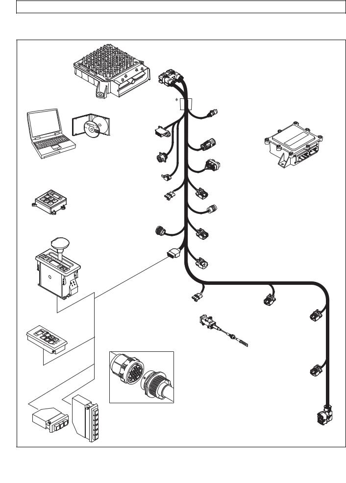
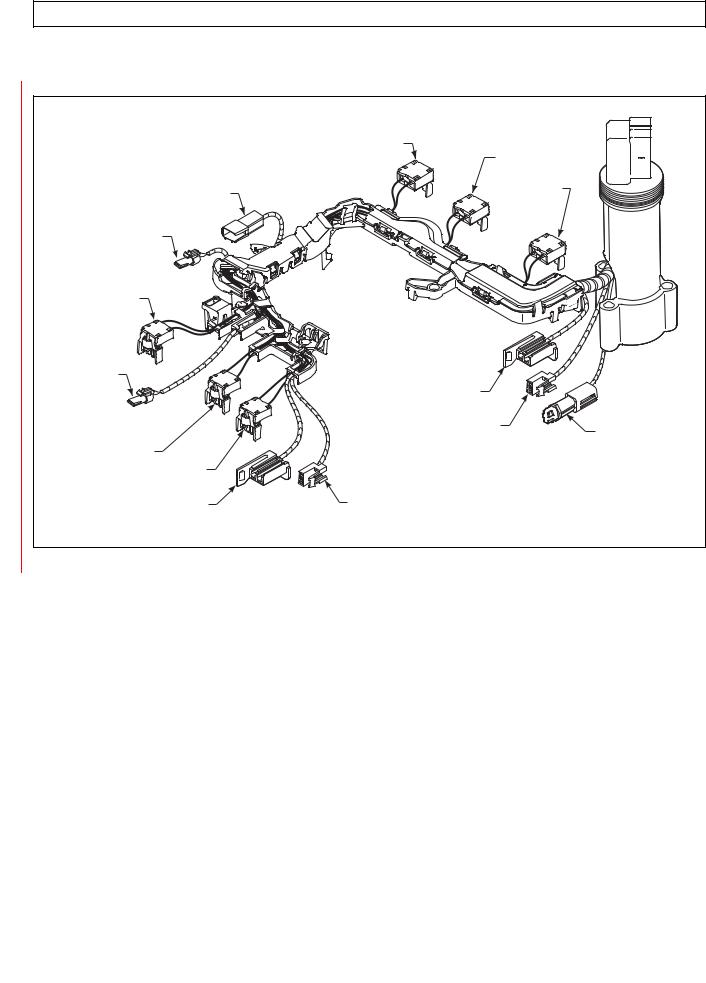
Figure 1–2 shows Allison 4th Generation electronic control components.
Allison 4th Generation Controls consist of the following elements:
•Remote 12V or 12/24V Max Feature Sealed Transmission Control Module (TCM)
•Remote Pushbutton or Lever Shift Selector
•Optional Secondary Shift Selector
•Throttle Position Sensor (TPS) or electronic engine throttle data or PWM signal
•Engine, Turbine, and Output Speed Sensors
•Control Module (Electro-Hydraulic Valve Body)
•Wiring Harnesses
•Vehicle Interface Module (VIM)
•Autodetect Feature
•TransID Feature
•Optional Retarder Controls
•Optional Engine Coolant Temperature Input
•Filter Life Switch (PS2)
NOTE: • All external harnesses are OEM supplied.
• The VIM is an OEM option.
|
Copyright © 2008 Allison Transmission, Inc. |
1–1 |
|
|
|
3000 AND 4000 PRODUCT FAMILIES TROUBLESHOOTING MANUAL—ALLISON 4th GENERATION CONTROLS
GENERAL DESCRIPTION
TRANSMISSION CONTROL MODULE (TCM)
ALLISON DOC™
FOR PC - SERVICE TOOL
COMPACT
PUSHBUTTON
SELECTOR
DIAGNOSTIC
TOOL
CONNECTOR
DEUTSCH 9-PIN DIAGNOSTIC TOOL CONNECTOR
SCI (J1587)  CONNECTOR
 (OPTIONAL)
RETARDER
MODULATION
REQUEST (RMR)
CONNECTOR
|
SENSOR HARNESS |
REMOTE LEVER |
CONNECTOR (OPTIONAL) |
SELEC TOR |
|
|
SHIFT |
|
SELEC TOR |
|
CONNECTOR |
|
VEHICLE |
|
|
INTERFACE |
|
J1939 |
MODULE |
|
(VIM) |
||
CONNECTOR |
||
|
||
VIW |
|
|
CONNECTOR |
|
|
(OPTIONAL) |
|
VIM
CONNECTOR
RETARDER ACCUMULATOR
CONNECTOR
TRANSFER CASE CONNEC TOR (3000 PRODUCT FAMILY 7-SPEED)
OUTPUT
SPEED SENSOR
CONNECTOR
RETARDER TEMP.


 SENSOR CONNECTOR
REMOTE PUSHBUTTON SELEC TOR
R
N
D
THROTTLE POSITION |
|
|
SENSOR (TPS) |
TURBINE |
|
CONNECTOR |
|
|
SPEED SENSOR |
ENGINE |
|
|
CONNECTOR |
SPEED |
THROTTLE |
(4000 PRODUCT |
SENSOR |
FAMILY) |
CONNECTOR |
|
POSITION |
|
|
SENSOR (TPS) |
|
|
 Bulkhead Connector (Optional)
STRIP PUSHBUTTON SHIFT SELEC TORS (EUROPEAN
OEM)
|
|
1 |
|
|
2 |
|
R |
3 |
|
|
|
D |
N |
D |
|
||
|
|
N |
|
|
R |
.
NOTE: Illustration is not to scale. Actual harness configuration may differ from this illustration.
RETARDER “PCS5”
SOLENOID
CONNECTOR
20-WAY TRANSMISSION FEEDTHROUGH HARNESS CONNECTOR
V09274.01.00A
Figure 1–2. Typical Allison 4th Generation Control Components
|
1–2 |
Copyright © 2008 Allison Transmission, Inc. |
|
|
|
3000 AND 4000 PRODUCT FAMILIES TROUBLESHOOTING MANUAL—ALLISON 4th GENERATION CONTROLS
GENERAL DESCRIPTION
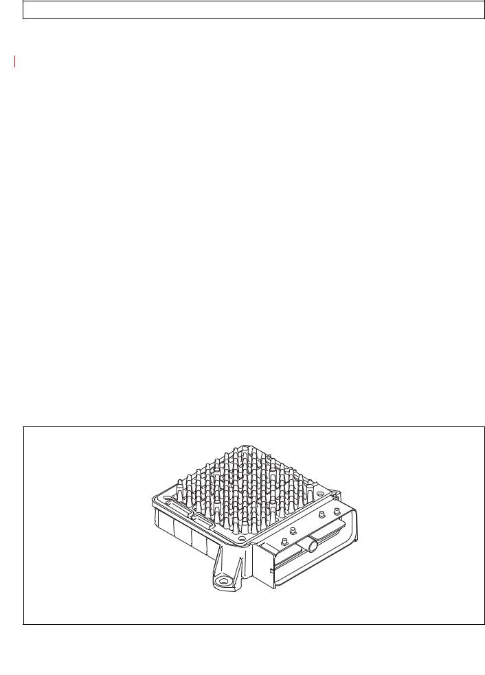
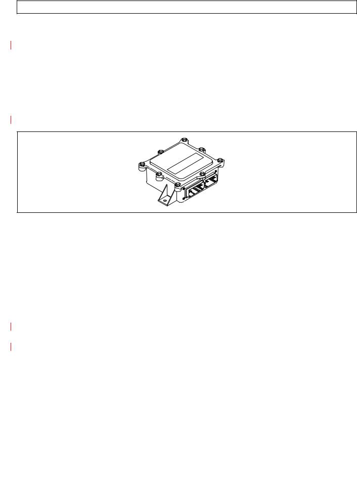
1–2. TRANSMISSION CONTROL MODULE (TCM)
The electronic control of the transmission is performed by a microcomputer. The microcomputer is an independent controller and is referred to as a Transmission Control Module (TCM). TCMs are available in both 12V and 12/24V configurations to match the configuration of the vehicle electrical system.
The TCM (Figure 1–3) contains the microcomputer which is the brain of the control system. The TCM receives and processes information defining:
•Shift selector
•Throttle position
•Sump/retarder temperature
•Pressure switch state
•Engine speed
•Turbine speed
•Transmission output speed.
The TCM uses the information to:
•Control transmission solenoids
•Supply system status
•Provide diagnostic information.
Each TCM has a date code laser etched on the outer case of the TCM. This is the date when the TCM passed final testing. This date is commonly used to denote the change configuration level of the TCM. It is normal for the TCM date displayed electronically to be a few days prior to the date shown on the label.
V09005.00.00
Figure 1–3. Transmission Control Module (TCM)
|
Copyright © 2008 Allison Transmission, Inc. |
1–3 |
|
|
|

3000 AND 4000 PRODUCT FAMILIES TROUBLESHOOTING MANUAL—ALLISON 4th GENERATION CONTROLS
GENERAL DESCRIPTION
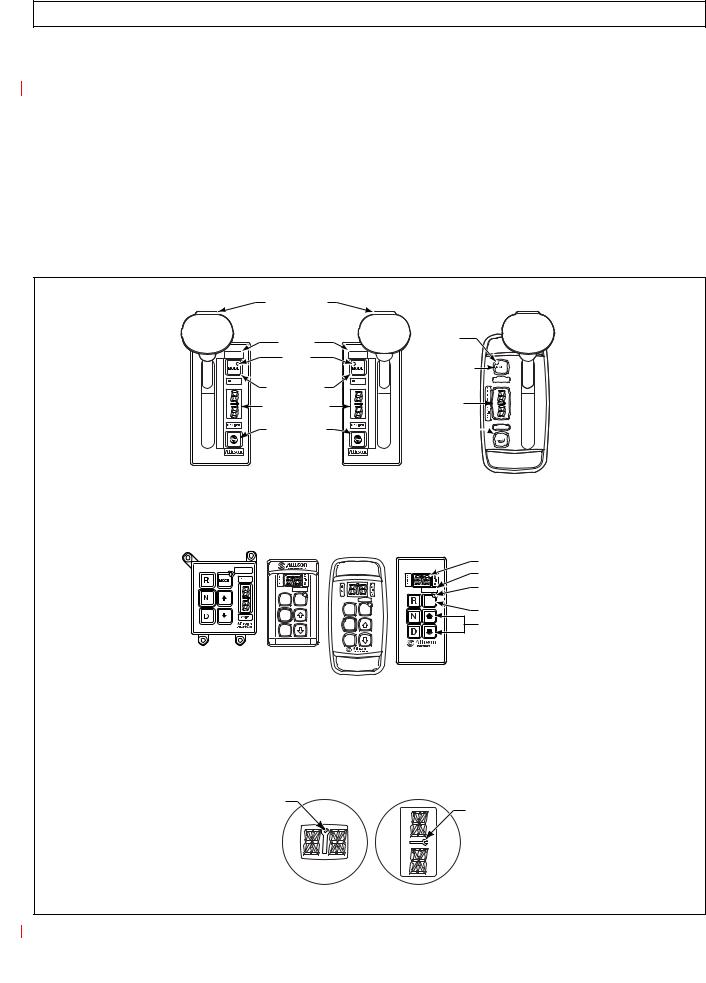
1–3. SHIFT SELECTOR
Pushbutton and lever shift selectors for the Allison 4th Generation Series are remote mounted from the TCM and communicate to the TCM via the J1939 communications data link. All shift selectors except the strip-type pushbutton have a dual digit vacuum fluorescent (VF) display and a mode indicator (LED). During normal transmission operation, illumination of the LED indicator shows that a secondary or special operating condition has been selected by pressing the MODE button. During diagnostic display mode, illumination of the LED indicator shows that the displayed Diagnostic Trouble Code (DTC) is active. Display brightness is regulated by the same vehicle potentiometer that controls dash light display brightness. More information on both types of shift selectors is continued below.
A.Pushbutton Shift Selector (Figure 1–4)
There are three full-function pushbutton shift selectors and a strip pushbutton shift selector. Strip pushbutton shift selectors are used primarily by non-North American OEMs. A full-function shift selector has a MODE button and diagnostic display capability through the dual digit vacuum fluorescent (VF) display. The strip pushbutton shift selector does not have a MODE button,
diagnostic capability, or adjustable illumination. The full-function pushbutton shift selector has
six (6) pushbuttons which are R (Reverse), N (Neutral), D (Drive), ↓ (Down), ↑ (Up), and MODE. Manual forward range downshifts and upshifts are made by pressing the ↓ (Down) or ↑ (Up) arrow buttons after selecting D (Drive). The N (Neutral) button has a raised lip to aid in finding it by touch.
The MODE button is pressed to select a secondary or special operating condition, such as ECONOMY shift schedule. Diagnostic information is obtained by pressing the ↑ (Up) and ↓ (Down) arrow buttons at the same time.
The strip pushbutton shift selector has either three or six range selection positions as shown in Figure 1–4. When a strip pushbutton shift selector is used, diagnostic information must be obtained by using the Allison DOC™ For PC–Service Tool, or a customer-supplied remote display.
|
1–4 |
Copyright © 2008 Allison Transmission, Inc. |
|
|
|
3000 AND 4000 PRODUCT FAMILIES TROUBLESHOOTING MANUAL—ALLISON 4th GENERATION CONTROLS
GENERAL DESCRIPTION
B.Lever Shift Selector (Figure 1–4)
The lever shift selector can have as many as six forward range positions (seven for the 7-speed models), as well as R (Reverse) and N (Neutral). There is a hold override button which must be pressed and held in order to move between certain selector positions. The hold override button must be pressed when shifting between R, N, and D. The hold override button is released when the desired selector position is reached. The selector lever can be moved freely between D and the numbered forward ranges without pressing the hold override button. The lever selector can be chosen with the lever on the left side or on the right side and with the R (Reverse) position toward the front or toward the rear of the selector. Diagnostic and oil level (if sensor is present) information is obtained from the LED display by pressing the “display mode” button.
HOLD OVERRIDE
BUTTON
|
MODE ID |
|
|
|
MODE |
|
|
|
INDICATOR |
R |
|
1 |
(LED) |
||
N |
|||
2 |
|
||
MODE BUTTON |
D |
||
3 |
|||
6 |
|||
4 |
|
||
DIGITAL DISPLAY* |
5 |
||
5 |
|||
4 |
|||
|
|
||
D |
|
3 |
|
N |
|
||
DISPLAY MODE |
2 |
||
R |
|||
1 |
|||
|
DIAGNOSTIC |
||
|
|
BUTTON
HOLD OVERRIDE
BUTTON
MODE |
INDICATOR |
(LED) |
MODE BUTTON |
MODE ID 

DIGITAL
DISPLAY*
DISPLAY MODE


 DIAGNOSTIC
BUTTON
SIX-SPEED, |
SEVEN-SPEED, |
CONTOURED |
|
LEFT-HAND |
RIGHT-HAND |
BEZEL |
|
LEVER SELECTOR |
LEVER SELECTOR |
|
|
|
|
DIGITAL DISPLAY* |
|
|
|
MODE ID |
|
|
|
MODE |
|
R MODE |
MODE |
INDICATOR (LED) |
|
N |
R MODE |
MODE BUTTON |
|
N |
Push simultaneously |
||
D |
|||
D |
to enter diagnostic |
||
|
|||
|
mode and fluid |
||
|
|
level check |
PUSHBUTTON SELECTORS
*NOTE: The first number displayed in the digital display is the highest forward range available and second number is range attained in selected position.
Visually confirm that the range selected was attained. If display is flashing, shift is inhibited.
SERVICE ICON
SERVICE ICON
Location of service icon on vertical and horizontal digital display |
V11058.00.00 |
Figure 1–4. Typical Allison 4th Generation Shift Selectors
|
Copyright © 2008 Allison Transmission, Inc. |
1–5 |
|
|
|
3000 AND 4000 PRODUCT FAMILIES TROUBLESHOOTING MANUAL—ALLISON 4th GENERATION CONTROLS
GENERAL DESCRIPTION
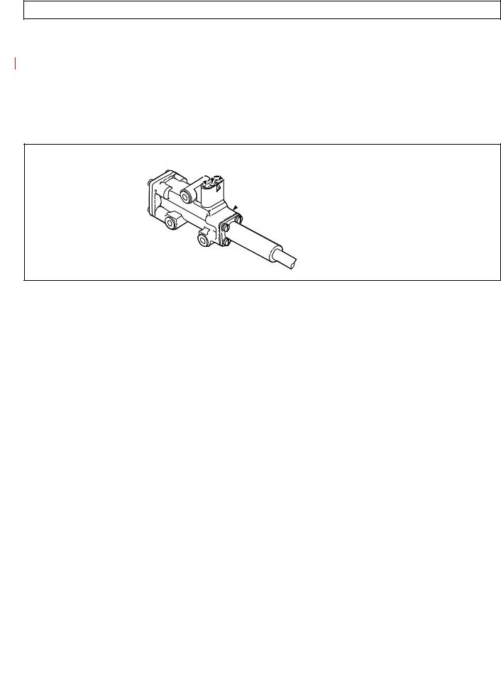
1–4. THROTTLE POSITION SENSOR (Figure 1–5)
The Throttle Position Sensor (TPS) can be mounted to the engine, chassis, or transmission. The TPS contains a pull actuation cable and a potentiometer. One end of the cable is attached to the engine fuel lever and the other, inside a protective housing, to the TPS potentiometer. Output voltage from the TPS is directed to the TCM through the external harness. The voltage signal indicates the throttle position and, in combination with other input data, determines shift timing.
A
 B
B
 C
C
 THROTTLE POSITION SENSOR
V00628
Figure 1–5. Throttle Position Sensor (Without Mounting Brackets)
|
1–6 |
Copyright © 2008 Allison Transmission, Inc. |
|
|
|
3000 AND 4000 PRODUCT FAMILIES TROUBLESHOOTING MANUAL—ALLISON 4th GENERATION CONTROLS
GENERAL DESCRIPTION
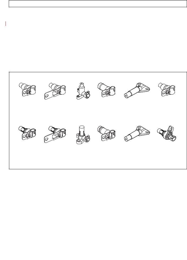
1–5. SPEED SENSORS (Figure 1–6)
Three speed sensors—engine speed, turbine speed, and output speed—provide information to the TCM. The engine speed signal is generated by ribs on the shell of the torque converter pump. The turbine speed signal is generated by the rotating-clutch housing spline contours. The output speed signal is generated by a toothed member attached to the output shaft (except for the 3000 Product Family 7-speed models, where the toothed member is the transfer case idler gear). The speed ratios between the various speed sensors allow the TCM to determine if the transmission is in the selected range. Speed sensor information is also used to control the timing of clutch apply pressures, resulting in the smoothest shifts possible. Hydraulic problems are detected by comparing the speed sensor information for the current range to that range’s speed sensor information stored in the TCM memory.
FORMER (BEFORE JANUARY, 2006)
3000 AND 4000 |
4000 |
3000 |
3000 |
3000 |
3000 AND 4000 |
PRODUCT FAMILIES |
PRODUCT FAMILY |
PRODUCT FAMILY |
PRODUCT FAMILY |
PRODUCT FAMILY |
PRODUCT FAMILIES |
ENGINE |
TURBINE |
TURBINE |
(EXCEPT 7-SPEED) |
7-SPEED OUTPUT |
OUTPUT (EXTERNAL), |
(EXTERNAL) |
(EXTERNAL) |
(INTERNAL) |
RETARDER OUTPUT |
(INTERNAL) |
4000 PRODUCT FAMILY |
|
|
|
(EXTERNAL) |
|
RETARDER |
CURRENT (JANUARY, 2006)
3000/4000 |
4000 |
3000 |
3000 |
3000 |
3000 AND 4000 |
PRODUCT FAMILIES |
PRODUCT FAMILY |
PRODUCT FAMILY |
PRODUCT FAMILY |
PRODUCT FAMILY |
PRODUCT FAMILIES |
ENGINE |
TURBINE |
TURBINE |
(EXCEPT 7-SPEED) |
7-SPEED OUTPUT |
OUTPUT (EXTERNAL), |
(EXTERNAL) |
(EXTERNAL) |
(INTERNAL) |
RETARDER OUTPUT |
(INTERNAL) |
4000 PRODUCT FAMILY |
|
|
|
(EXTERNAL) |
|
RETARDER |
|
|
|
|
|
V09819.00.00 |
Figure 1–6. Speed Sensors
|
Copyright © 2008 Allison Transmission, Inc. |
1–7 |
|
|
|

3000 AND 4000 PRODUCT FAMILIES TROUBLESHOOTING MANUAL—ALLISON 4th GENERATION CONTROLS
GENERAL DESCRIPTION
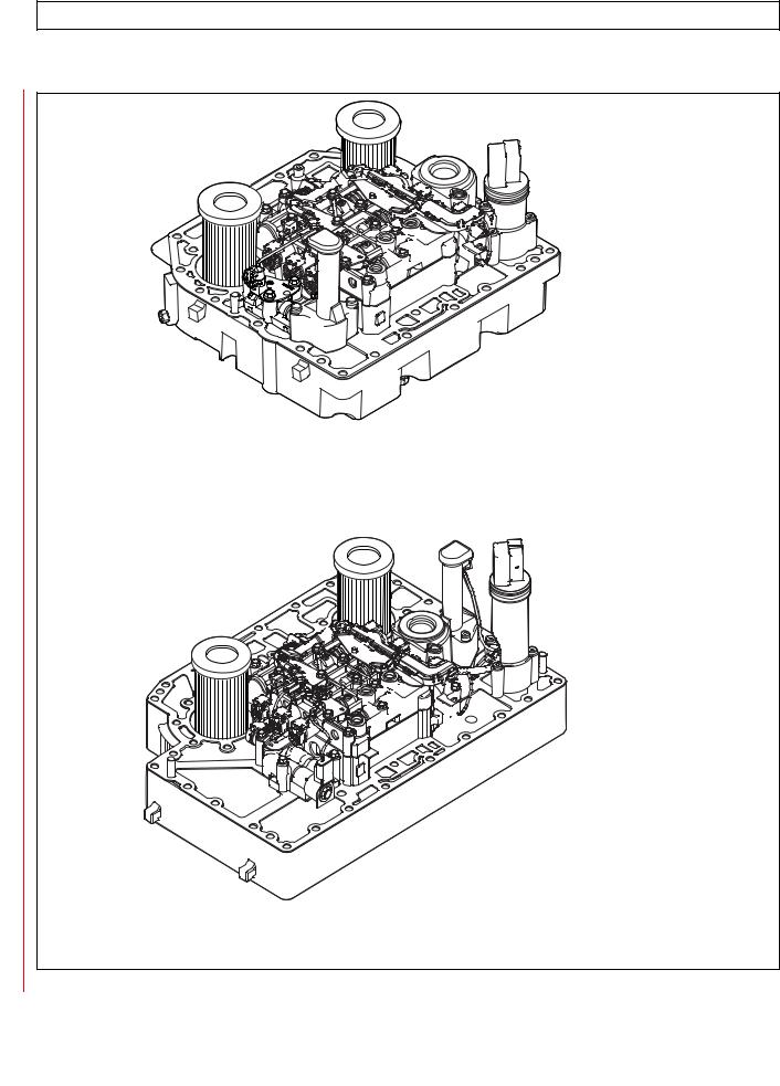
1–6. CONTROL MODULE (Figures 1–7 and 1–8)
The Allison 4th Generation Series transmission control module contains a main body assembly and solenoid valve body assembly, which are mounted to an aluminum channel plate. The TCM issues commands to various solenoids in the two valve bodies to govern fluid flow to the clutches (including torque converter clutch). The solenoids produce an output pressure that is proportional to current from the TCM. Hence, the solenoids are referred to as pressure control solenoids (PCS).
6-SPEED |
7-SPEED |
3000 PRODUCT FAMILY |
3000 PRODUCT FAMILY |
CONTROL MODULE |
CONTROL MODULE |
6-SPEED |
7-SPEED |
4000 PRODUCT FAMILY |
4000 PRODUCT FAMILY |
CONTROL MODULE |
CONTROL MODULE |
|
V09276.00.00 |
Figure 1–7. Allison 4th Generation Control Modules
|
1–8 |
Copyright © 2008 Allison Transmission, Inc. |
|
|
|
3000 AND 4000 PRODUCT FAMILIES TROUBLESHOOTING MANUAL—ALLISON 4th GENERATION CONTROLS
GENERAL DESCRIPTION
6-SPEED W/PROGNOSTICS
3000 PRODUCT FAMILY
CONTROL MODULE
6-SPEED W/PROGNOSTICS
4000 PRODUCT FAMILY V09276.00.00.A
CONTROL MODULE
Figure 1–8. Allison 4th Generation Control Mudules with Prognostics
|
Copyright © 2008 Allison Transmission, Inc. |
1–9 |
|
|
|

3000 AND 4000 PRODUCT FAMILIES TROUBLESHOOTING MANUAL—ALLISON 4th GENERATION CONTROLS
GENERAL DESCRIPTION
The main valve body assembly contains the following:
•Main pressure regulator valve
•Control main regulator valve
•Converter flow valve
•Lube regulator valve
•Converter regulator valve
•Exhaust backfill valve
•Two latching logic valves
•On/Off solenoid SS1.
The solenoid valve body assembly contains the following:
•Pressure control solenoid MAIN MOD
•PCS1 (A trim)
•PCS2 (B trim)
•PCS3 (C trim)
•PCS4 (D trim)
•TCC (lockup)
•Diagnostic pressure switch PS1
•Filter Life Switch (PS2)
•Five solenoid regulator valves
•One diagnostic valve.
The low valve body assembly (in 3000 and 4000 Product Families 7-speed models) contains solenoid PCS6 (C6) and one ON/OFF solenoid SS2 (C6 enable). Refer to the appropriate service manual for valve locations.
The Allison 4th Generation controls system includes a main modulation solenoid. Modulated main pressure results in improved cooler flow and reduced pump losses when throttle position and output speed is low. The Allison 4th Generation Controls TCM commands the main mod solenoid ON when all of the following conditions are simultaneously met:
•Sump temperature is greater than –80ºC (–112ºF) and less than 150ºC (302ºF).
•Engine speed less than 1200 rpm in all ranges except neutral. There are no restrictions on engine speed in neutral.
•Throttle percentage less than 15 percent in reverse, low (7-speed), first, or second range. Main mod may be commanded ON in neutral at any throttle position.
•Output speed is less than 250 rpm in neutral, reverse, low (7-speed), first, or second range.
•The PTO input to the TCM indicates the PTO is OFF.
•Shift not in progress.
The TCM may activate the main mod solenoid for improved clutch control and transmission response during other unusual operating situations.
A temperature sensor (thermistor) is located in the internal wiring harness. Changes in sump fluid temperature are indicated by changes in sensor resistance, which changes the signal sent to the TCM. Refer to the chart in Appendix Q.
The oil level sensor (OLS) is a float type device mounted on the control module channel plate. The OLS senses transmission fluid level by electronically measuring the buoyancy forces on the float. The sensor operates on
|
1–10 |
Copyright © 2008 Allison Transmission, Inc. |
|
|
|
3000 AND 4000 PRODUCT FAMILIES TROUBLESHOOTING MANUAL—ALLISON 4th GENERATION CONTROLS
GENERAL DESCRIPTION
5VDC supplied by the TCM. The oil level sensor is available on any 3000 and 4000 Product Families transmissions except the 3000 7-speed transmissions.
The diagnostic pressure switch PS1 is mounted on the solenoid valve body assembly and performs the following two functions:
•When the C5 clutch is filled, PS1 senses the PCS2 solenoid regulator valve position to verify proper C3 clutch control in reverse, neutral, and first range.
•When the C5 clutch is exhausted, as in second through sixth ranges, PS1 verifies the position of the C1 and C2 latch valves.
The turbine speed sensor is mounted on the control module for the 3000 Product Family transmissions. The turbine speed sensor is directed at the rotating-clutch housing. The turbine speed sensor on the 4000 Product Family transmission is located on the outside of the main housing.
A.Control System Prognostics Operation and Display
The Prognostics Package includes the following functions:
•Oil Life Monitor
•Filter Life Monitor
•Transmission Health Monitor
Use the Allison DOC™ For PC–Service Tool to review the current status of any of these functions and a history of indicator resets. Use the Allison shift selector to review the current status of any of these functions, provided the function being checked is in its specific display mode. See the selector information section for that procedure.
When a specified threshold is detected for any of the prognostic functions, the SERVICE TRANS indicator (an open-ended wrench icon located between the range select and range monitor digits in the Allison shift selector) illuminates to alert the operator. The lamp strategy for the icon varies, either flashing, or steady, to indicate to the operator which function detected the threshold value was reached.
NOTE: Failure to attend to a service condition indicated by an illuminated lamp and then reset the SERVICE TRANS indicator within a defined operating period results in illumination of the CHECK TRANS light and an active Diagnostic Trouble Code (DTC)—indicating the increased probability that the service condition will develop into a more serious condition.
B.Filter Life Valve Body
The Filter Life Valve Body Assembly includes the parts listed here and also shown in Figure 2.
•Filter Life Valve Body
•Filter Life Valve
•Return Spring
•Valve Stop
•Retaining Clip
•Pressure Switch 2 (Filter Life)
•M6 x 45 Long Screws (4)
This assembly cannot be retrofitted to the former channel plate assemblies. Make sure all updates listed in this section and all other requirements are met prior to using the Prognostics features.
|
Copyright © 2008 Allison Transmission, Inc. |
1–11 |
|
|
|

3000 AND 4000 PRODUCT FAMILIES TROUBLESHOOTING MANUAL—ALLISON 4th GENERATION CONTROLS
GENERAL DESCRIPTION
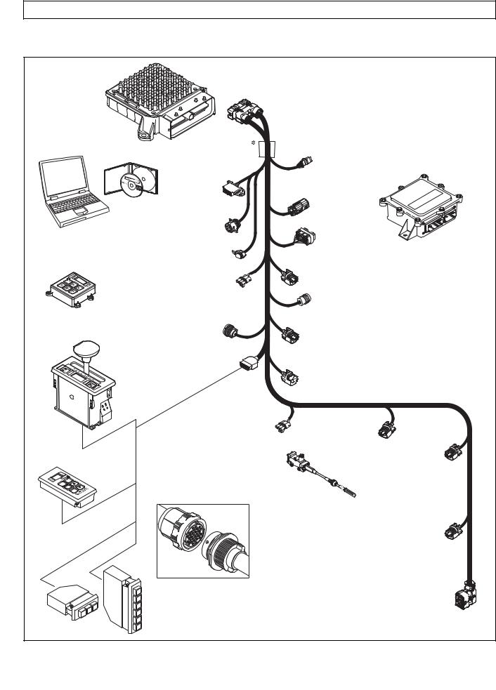
1–7. WIRING HARNESSES
A.External Wiring Harness (Figure 1–9)
The TCM uses a single 80-way connector, which is used to receive input from the following:
Transmission |
TPS |
Diagnostic tool connector |
Engine |
Vehicle interface module (VIM) |
Retarder |
Turbine |
Retarder control module |
Retarder temperature sensor |
Output speed sensor |
Shift selector |
Accumulator |
|
|
Filter life switch (PS2) |
Many harnesses will include a bulkhead fitting to separate cab and chassis components. Also, many different styles and materials for harnesses are likely to be encountered.
NOTE: Allison Transmission is providing for service of wiring harnesses and wiring harness components as follows:
•Repair parts for the internal wiring harness and for wiring harness components attached to the shift selector will be available through the Allison Transmission Parts Distribution Center (PDC). Use the P/N from your appropriate parts catalog or from Appendix E in this manual. Allison Transmission is responsible for warranty on these parts.
•Repair parts for the external harnesses and external harness components must be obtained from St. Clair Technologies Inc. (SCTI). SCTI provides parts to any Allison customer or OEM and is responsible for warranty on these parts. SCTI recognizes Allison Transmission, manufacturers, and SCTI part numbers. SCTI provides a technical HELPLINE at 519-627-1673 (Wallaceburg). SCTI will have parts catalogs available. The SCTI addresses and phone numbers for parts outlets are:
St. Clair Technologies, Inc. |
St. Clair Technologies, Inc. |
920 Old Glass Road |
Calle Damanti S/N Col |
Wallaceburg, Ontario, Canada N8A 4L8 |
Guadalupe—Guaymas |
Phone: 519-627-1673 |
Sonora, Mexico 85440 |
Fax: 519-627-4227 |
Phone: 011-526 2222-43834 |
|
Fax: 011-526-2222-43553 |
• SCTI is the source for external harness repair parts.
|
1–12 |
Copyright © 2008 Allison Transmission, Inc. |
|
|
|
3000 AND 4000 PRODUCT FAMILIES TROUBLESHOOTING MANUAL—ALLISON 4th GENERATION CONTROLS
GENERAL DESCRIPTION
TRANSMISSION CONTROL MODULE (TCM)
ALLISON DOC™
FOR PC - SERVICE TOOL
COMPACT
PUSHBUTTON
SELECTOR
DIAGNOSTIC
TOOL
CONNECTOR
DEUTSCH 9-PIN DIAGNOSTIC TOOL CONNECTOR
SCI (J1587)  CONNECTOR
 (OPTIONAL)
RETARDER
MODULATION
REQUEST (RMR)
CONNECTOR
|
SENSOR HARNESS |
REMOTE LEVER |
CONNECTOR (OPTIONAL) |
SELEC TOR |
|
|
SHIFT |
|
SELEC TOR |
|
CONNECTOR |
|
VEHICLE |
|
|
INTERFACE |
|
J1939 |
MODULE |
|
(VIM) |
||
CONNECTOR |
||
|
||
VIW |
|
|
CONNECTOR |
|
|
(OPTIONAL) |
|
VIM
CONNECTOR
RETARDER ACCUMULATOR
CONNECTOR
TRANSFER CASE CONNEC TOR (3000 PRODUCT FAMILY 7-SPEED)
OUTPUT
SPEED SENSOR
CONNECTOR
RETARDER TEMP.


 SENSOR CONNECTOR
REMOTE PUSHBUTTON SELEC TOR
R
N
D
THROTTLE POSITION |
|
|
SENSOR (TPS) |
TURBINE |
|
CONNECTOR |
|
|
SPEED SENSOR |
ENGINE |
|
|
CONNECTOR |
SPEED |
THROTTLE |
(4000 PRODUCT |
SENSOR |
FAMILY) |
CONNECTOR |
|
POSITION |
|
|
SENSOR (TPS) |
|
|
 Bulkhead Connector (Optional)
STRIP PUSHBUTTON SHIFT SELEC TORS (EUROPEAN
OEM)
|
1 |
|
2 |
R |
3 |
|
N
DD N R
NOTE: Illustration is not to scale. Actual harness configuration may differ from this illustration.
RETARDER “PCS5”
SOLENOID
CONNECTOR
20-WAY TRANSMISSION FEEDTHROUGH HARNESS CONNECTOR
V09274.01.00A
Figure 1–9. Typical 4th Generation Electronic Controls External Wiring Harnesses
|
Copyright © 2008 Allison Transmission, Inc. |
1–13 |
|
|
|
3000 AND 4000 PRODUCT FAMILIES TROUBLESHOOTING MANUAL—ALLISON 4th GENERATION CONTROLS
GENERAL DESCRIPTION
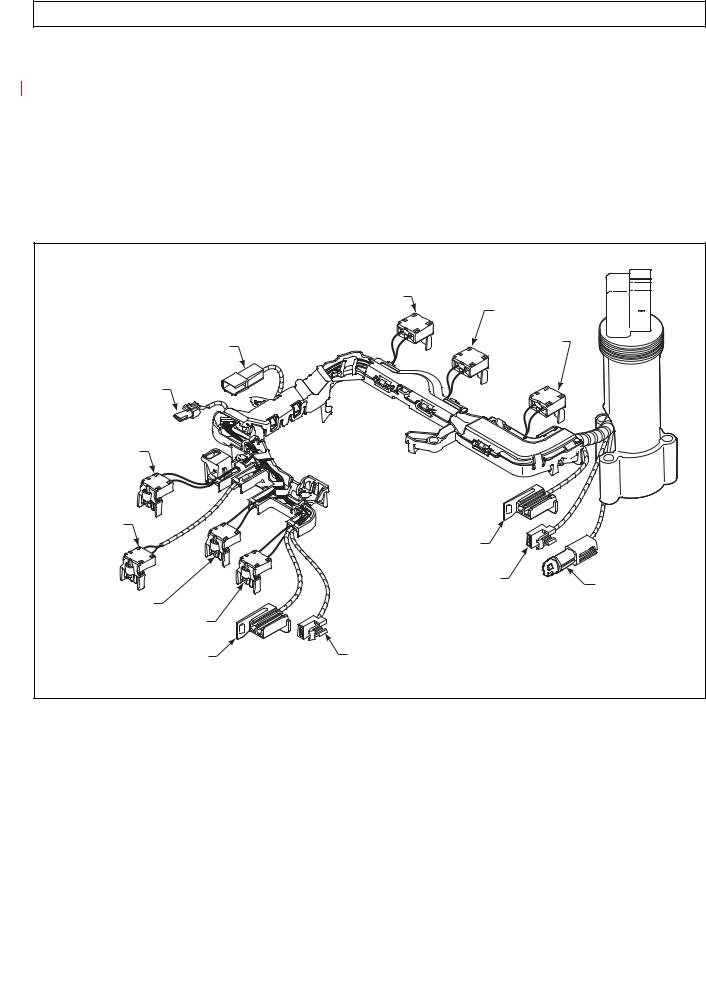
B.Internal Wiring Harness (Figure 1–10)
The internal wiring harness provides connection between the following:
•External harness
•Pressure control and shift solenoids
•Oil level sensor
•Diagnostic pressure switch
•Temperature sensor
•Turbine speed sensor.
|
TCC (LOCKUP) |
|
|
|
PCS1 (C1) |
PS1 DIAGNOSTIC |
|
PCS2 (C2/C3) |
PRESSURE SWITCH |
|
|
NT1 TURBINE |
|
|
SPEED SENSOR |
|
|
(3000 ONLY) |
|
|
MAIN MOD |
|
|
PCS6 |
|
|
(C6, 7-SPEED) |
SS1 |
|
|
|
|
|
ON/OFF |
|
|
OIL LEVEL SENSOR |
OIL |
|
(4000 ONLY) |
|
|
TEMPERATURE |
|
PCS4 (C4) |
|
|
|
SENSOR |
|
PCS3 (C3\C5) |
|
|
SS2 |
OIL LEVEL SENSOR |
|
(3000 AND 4000 PRODUCT |
(3000, EXCEPT 7-SPEED) |
|
FAMILIES 7-SPEED C6 ENABLE) |
|
|
|
|
V09251.00.00 |
Figure 1–10. Allison 4th Generation Internal Wiring Harness
|
1–14 |
Copyright © 2008 Allison Transmission, Inc. |
|
|
|
3000 AND 4000 PRODUCT FAMILIES TROUBLESHOOTING MANUAL—ALLISON 4th GENERATION CONTROLS
GENERAL DESCRIPTION
|
TCC (LOCKUP) |
|
|
|
PCS1 (C1) |
PS1 DIAGNOSTIC |
|
PCS2 (C2/C3) |
PRESSURE SWITCH |
|
|
NT1 TURBINE |
|
|
SPEED SENSOR |
|
|
(3000 ONLY) |
|
|
MAIN MOD |
|
|
PS2 |
|
|
FILTER LIFE |
SS1 |
|
|
ON/OFF |
|
|
OIL LEVEL SENSOR |
OIL |
|
(4000 ONLY) |
|
|
TEMPERATURE |
|
PCS4 (C4) |
|
|
|
SENSOR |
|
PCS3 (C3\C5) |
|
|
SS2 |
OIL LEVEL SENSOR |
|
(3000 AND 4000 PRODUCT |
(3000, EXCEPT 7-SPEED) |
|
FAMILIES 7-SPEED C6 ENABLE) |
|
|
|
|
V09251.00.00.A |
Figure 1–11. Allison 4th Generation Internal Wiring Harness with Prognostics
|
Copyright © 2008 Allison Transmission, Inc. |
1–15 |
|
|
|
3000 AND 4000 PRODUCT FAMILIES TROUBLESHOOTING MANUAL—ALLISON 4th GENERATION CONTROLS
GENERAL DESCRIPTION
1–8. VEHICLE INTERFACE MODULE (Figure 1–12)
The vehicle interface module (VIM) provides relays, fuses, and connection points for interface with the output side of the vehicle electrical system. VIMs are available for both 12V and 24V electrical systems. The VIM for 12V systems uses all 12V relays. The VIM for 24V systems has all 24V relays. Refer to the appropriate parts catalog for the transmission assembly number that you are servicing for detailed parts information. Refer to Pages D–15 and D–16 for VIM wire number and terminal information.
Some OEMs may provide their own equivalent for the VIM which performs the same functions as the VIM shown in Figure 1–12.
V00631.02
Figure 1–12. Vehicle Interface Module (VIM)
1–9. AUTODETECT FEATURE
Autodetect is active on the first 25 engine starts and, in the case of throttle source detection logic, may continue past 25 ignition cycles until a valid source is determined (details follow in A through D below). Autodetect takes place within the first 30 seconds of each engine start monitored. Autodetect searches for the presence of the following transmission components or data inputs in the priority listed:
Retarder |
Present, Not Present |
Oil Lever Sensor (OLS) |
Present, Not Present |
Throttle |
TPS, J1587, J1939 * |
Engine Coolant Temperature |
Sensor, J1939, J1587 |
* No Throttle Autodetect with MY09
Even after autodetect has been completed, it can be reset to monitor an additional group of engine starts. Reset may be necessary if a device known to be present is not detected or if an autodetectable component or sensor was added after the initial vehicle build. Reset is accomplished by using Allison DOC™ For PC–Service Tool. To use the Allison DOC™ For PC–Service Tool, select “RESET AUTODETECT” to search for all four devices. Select “RESET AUTODETECT RETARDER” to search for a retarder only. Selecting “RESET ADAPTIVE SHIFT PARAMETERS” will not reset autodetect logic.
The Allison DOC™ For PC–Service Tool can also be used to override autodetect and manually enter the component or sensor to be recognized by the TCM by changing appropriate “customer modifiable constants” (CMC). The four items above are the only CMCs that are autodetectable. Other CMCs can be changed at any time and are not related to autodetect. Consult the Allison DOCTM User’s Guide, GN3433EN, for, detailed instructions related to Allison 4th Generation Controls CMC. Additional details for each of the four autodetectable features are given below.
|
1–16 |
Copyright © 2008 Allison Transmission, Inc. |
|
|
|

3000 AND 4000 PRODUCT FAMILIES TROUBLESHOOTING MANUAL—ALLISON 4th GENERATION CONTROLS
GENERAL DESCRIPTION
A.Retarder
Autodetect searches for the presence of pressure control solenoid 5 (PCS5) to the retarder during the first 35 engine ignition cycles. Retarder autodetect will countdown for a maximum of 35 ignition cycles while recording detections of a retarder. A retarder will be identified as present and the retarder autodetect logic will stop once it is detected for three consecutive ignition cycles. If the ignition cycle counter completes the 35 cycles before there are three consecutive detections of a retarder, the software will log that there is no retarder and the retarder autodetect logic will stop. If the autodetect logic is not satisfied during the first 35 engine starts, the retarder is not detected and will not function on subsequent engine starts.
If a retarder is present but is not detected by autodetect, the retarder will not function. Be sure to determine that the retarder is functioning properly
WARNING: immediately after the 35th engine start. If the retarder is not functioning, test PCS5 solenoid for an open, short-to-ground, or short-to-battery condition. Use
the Allison DOC™ For PC–Service Tool to reset retarder autodetect or to manually select the presence of the retarder after the PCS5 circuit is repaired.
B. Oil Level Sensor (OLS)
NOTE: If an OLS is known to be present but has not been detected, a possible cause is that the transmission fluid level is too low. Determine the fluid level before beginning the OLS troubleshooting.
Oil level sensor autodetect will countdown for a maximum of 25 engine starts while recording detections of an OLS. The TCM monitors the OLS input voltage on wire 116. OLS input voltage must exceed a predetermined level for the TCM to record a detection. Additionally, OLS detection must occur within 12.5 seconds on any given engine start. An OLS will be identified as present and the OLS autodetect logic will stop once it is detected during any single engine start.
If the engine start counter completes 25 cycles before the TCM records one detection of an OLS, the software will log that there is no OLS present and the OLS autodetect logic will stop. Then the TCM concludes that no OLS is present.
No OLS diagnostics take place until the OLS is detected. Frequently test for the presence of oil level diagnostics if the transmission is known to contain an OLS. If an OLS is known to be present, but has not been detected, troubleshooting the OLS circuit is required. After the OLS circuit is repaired, reset autodetect or manually select the OLS function using the Allison DOC™ For PC–Service Tool.
C.Throttle Source
Throttle autodetect will increment a counter for a throttle source on each engine start during which the possible throttle source is detected. When the counter for any of the sources indicates five consecutive detections, the software will set a “confidence flag” to indicate that this is an available throttle source. Multiple throttle sources can be detected on a single engine start and multiple confidence flags can be set. There is no limit to the number of engine starts for autodetection of the throttle source until a confidence flag is set for a source. Once a confidence flag is set for any one of the sources, a counter begins to countdown for 15 additional engine starts. During the entire autodetect period, the software will use the highest priority source as the throttle source if multiple sources are detected before any confidence flags are set. Once a confidence flag is set, that source is used as the source for the throttle signal. When the countdown period is complete, the software will use the highest priority throttle source having a confidence flag set and the autodetect logic will stop.
|
Copyright © 2008 Allison Transmission, Inc. |
1–17 |
|
|
|

3000 AND 4000 PRODUCT FAMILIES TROUBLESHOOTING MANUAL—ALLISON 4th GENERATION CONTROLS
GENERAL DESCRIPTION
D.Engine Coolant Temperature
Engine coolant temperature sensor autodetect will countdown for a total of 25 engine starts while recording detections of engine coolant temperature sources. A “confidence flag” will be set once a source is detected for five consecutive engine starts. Multiple sources detected before a confidence flag is set or multiple confidence flags will result in the highest priority source being used as the engine coolant temperature source. Multiple sources can be detected on a single engine start cycle.
1–10. TRANSID (TID)
The TransID feature enables the TCM to recognize various transmission hardware configurations and select an appropriate software calibration. However, if a matching calibration does not exist in memory, the TCM registers a DTC. Furthermore, TID only works when the controller and transmission have the same generation controls. Thus, TID will not allow an Allison 4th Generation TCM to recognize a transmission with WTEC III controls, nor will TID allow a WTEC III ECU to recognize a transmission with Allison 4th Generation Controls.
The TCM senses the transmission configuration using TID wire 176. In initial versions of Allison 4th Generation Controls, wire 176 is connected to high side driver 1 (HSD1), wire 111, in the internal wiring harness. HSD1 supplies power to PCS6 and MAIN MOD solenoids. This wiring configuration is designated TID A.
Whenever a TID level change is to be made, the new TID level calibration will be added to the PROM Calibration Configurator System (PCCS) before the change (s) is (are) made in production to the transmissions. All TCMs programmed and sold after that date will be loaded with the new TID calibration. These TCMs will contain calibrations for the new level transmission and all previous TID levels and will automatically load the correct calibration for the transmission based on the TID signal sensed by Autodetect during the first 25 engine starts.
|
1–18 |
Copyright © 2008 Allison Transmission, Inc. |
|
|
|
3000 AND 4000 PRODUCT FAMILIES TROUBLESHOOTING MANUAL—ALLISON 4th GENERATION CONTROLS
GENERAL DESCRIPTION
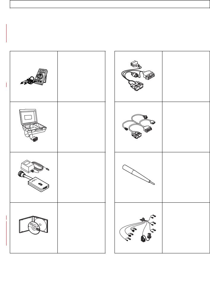
1–11. SPECIAL ELECTRONIC/ELECTRICAL TOOLS
All tools listed are essential for overhaul, maintenance, and/or recalibration of the 3000 and 4000 Product Families electronic and electrical systems. The tools listed below are available for purchase from SPX/Kent-Moore.
Table 1–1. Essential Tools
x
COM |
A |
10 A
J 39700
J 42455-A |
J 44950 |
J 34520-A
Digital
Volt/Ohmmeter
J 39700
Univeral Breakout Box
J 42455-A
Load Box
J 44950
Allison DOC™ For
PC–Service Tool
NOTE: J 44950 is superseded for each new release of Allison DOC™ For PC–Service Tool
J 47275
TCM Breakout
Harness Adapter
NOTE: Used with J 39700.
J 47275
J 47276
“T” Breakout and TCM
Reflashing Harness
J 47276
J 47277
Terminal Probe
NOTE: J 47277 is now included in the J 39197-A Kit.
J 47277
* |
J 47279 |
* |
3000 and 4000 Product |
|
|
|
Families Breakout Harness |
*NOTE: 4000 Product Family |
|
V09224.01.00 |
|
|
Copyright © 2008 Allison Transmission, Inc. |
1–19 |
|
|
|
3000 AND 4000 PRODUCT FAMILIES TROUBLESHOOTING MANUAL—ALLISON 4th GENERATION CONTROLS
GENERAL DESCRIPTION
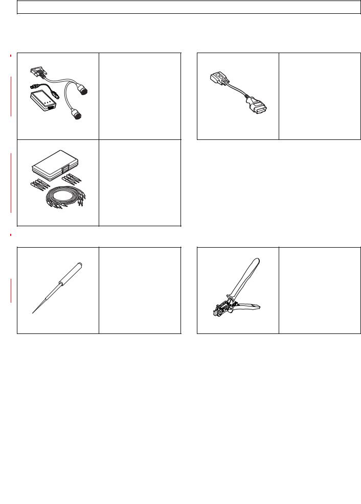
Table 1–1. Essential Tools (cont’d)
|
J 47943-A |
J 47949-A |
|
or |
|
|
or |
|
|
J 47943 |
|
|
J 47949 |
|
|
DPA4 (Plus) USB |
|
|
GMLAN Cable |
|
|
Translator Device Kit |
|
|
|
|
J 47943 |
|
J 47949 |
|
J 39197 |
|
|
or |
|
|
J 39197-A |
|
|
Jumper Kit |
|
|
NOTE: J 47277 Terminal |
|
|
Probe is now included in |
|
|
the J 39197-A Kit. |
|
J 39197-A |
|
|
Table 1–2. Available Tools
J 38125-12A
Terminal Remover (80-way connector) GM P/N: 12094429
J 47139 (Former) 63811-6000 (Current) Crimper
J 38125-12A |
J 47139 |
|
1–20 |
Copyright © 2008 Allison Transmission, Inc. |
|
|
|
Loading...