


MOTORHOME SERIES
3000/4000
OPERATOR’S
MANUAL

Operator’s
Manual
2005 FEBRUARY
Rev. 1 2005 SEPTEMBER
OM3349EN
Allison Transmission
VOCATIONAL MODELS
Motorhome Series (MH) Transmissions
3000 and 4000 Product Families
WTEC III Controls and Allison 4th Generation Controls
3000 MH
4000 MH
Printed in USA |
Copyright © 2005 General Motors Corporation |
NOTES
2
TABLE OF CONTENTS
INTRODUCTION
KEEPING THAT ALLISON ADVANTAGE . . . . . . . . . . . . . . . . . . . . . . . . 7
A BRIEF DESCRIPTION OF THE ALLISON MOTORHOME SERIES TRANSMISSIONS . . . . . . . . . . . . . . . . . . . . . . . . . . . . . . . . . . . . . . 12
ELECTRONIC CONTROL SYSTEM . . . . . . . . . . . . . . . . . . . . . . . . . . . 12 TORQUE CONVERTER . . . . . . . . . . . . . . . . . . . . . . . . . . . . . . . . . . . 13 PLANETARY GEARS AND CLUTCHES . . . . . . . . . . . . . . . . . . . . . . . . 14 COOLER CIRCUIT . . . . . . . . . . . . . . . . . . . . . . . . . . . . . . . . . . . . . . 14 RETARDER . . . . . . . . . . . . . . . . . . . . . . . . . . . . . . . . . . . . . . . . . . . 15
SHIFT SELECTORS
DESCRIPTION OF AVAILABLE TYPES . . . . . . . . . . . . . . . . . . . . . . . . . 16 INTRODUCTION . . . . . . . . . . . . . . . . . . . . . . . . . . . . . . . . . . . . . . . 17 LEVER SHIFT SELECTOR . . . . . . . . . . . . . . . . . . . . . . . . . . . . . . . . . 18 PUSHBUTTON SHIFT SELECTOR . . . . . . . . . . . . . . . . . . . . . . . . . . . . 20 RANGE SELECTION . . . . . . . . . . . . . . . . . . . . . . . . . . . . . . . . . . . . . 21
DRIVING TIPS
CHECK TRANS LIGHT . . . . . . . . . . . . . . . . . . . . . . . . . . . . . . . . . . . 26 DIAGNOSTIC CODES . . . . . . . . . . . . . . . . . . . . . . . . . . . . . . . . . . . . 27 ACCELERATOR CONTROL . . . . . . . . . . . . . . . . . . . . . . . . . . . . . . . . 27 DOWNSHIFT AND DIRECTION CHANGE INHIBITOR FEATURE . . . . . . . 27 USING THE ENGINE TO SLOW THE VEHICLE . . . . . . . . . . . . . . . . . . . 29 USING THE HYDRAULIC RETARDER . . . . . . . . . . . . . . . . . . . . . . . . . 29 ADAPTING SHIFTS . . . . . . . . . . . . . . . . . . . . . . . . . . . . . . . . . . . . . 32 RANGE PRESELECTION . . . . . . . . . . . . . . . . . . . . . . . . . . . . . . . . . . 34 COLD WEATHER STARTS . . . . . . . . . . . . . . . . . . . . . . . . . . . . . . . . . 34 DRIVING ON SNOW OR ICE . . . . . . . . . . . . . . . . . . . . . . . . . . . . . . . 35 ROCKING OUT . . . . . . . . . . . . . . . . . . . . . . . . . . . . . . . . . . . . . . . . 36 HIGH FLUID TEMPERATURE . . . . . . . . . . . . . . . . . . . . . . . . . . . . . . 36 PARKING BRAKE . . . . . . . . . . . . . . . . . . . . . . . . . . . . . . . . . . . . . . 37 TOWING OR PUSHING . . . . . . . . . . . . . . . . . . . . . . . . . . . . . . . . . . . 38 PRIMARY/SECONDARY SHIFT SCHEDULES . . . . . . . . . . . . . . . . . . . . 38 CRUISE CONTROL OPERATION . . . . . . . . . . . . . . . . . . . . . . . . . . . . . 38 TURNING OFF THE VEHICLE . . . . . . . . . . . . . . . . . . . . . . . . . . . . . . 39
POWER TAKEOFF OPERATION
ENGINE-DRIVEN POWER TAKEOFF (PTO) . . . . . . . . . . . . . . . . . . . . . 40
3
CARE AND MAINTENANCE |
|
PERIODIC INSPECTIONS . . . . . . . . . . . . . . . . . . . . . . . . . . . . . . . . . |
41 |
PREVENT MAJOR PROBLEMS . . . . . . . . . . . . . . . . . . . . . . . . . . . . . . |
41 |
IMPORTANCE OF PROPER FLUID LEVEL . . . . . . . . . . . . . . . . . . . . . . |
42 |
FLUID LEVEL CHECK USING PUSHBUTTON OR LEVER SHIFT |
|
SELECTOR . . . . . . . . . . . . . . . . . . . . . . . . . . . . . . . . . . . . . . . . . . . |
43 |
MANUAL FLUID CHECK PROCEDURE . . . . . . . . . . . . . . . . . . . . . . . |
47 |
COLD CHECK . . . . . . . . . . . . . . . . . . . . . . . . . . . . . . . . . . . . . . . . . |
49 |
HOT CHECK . . . . . . . . . . . . . . . . . . . . . . . . . . . . . . . . . . . . . . . . . . |
50 |
RECOMMENDED AUTOMATIC TRANSMISSION FLUID AND VISCOSITY |
|
GRADE . . . . . . . . . . . . . . . . . . . . . . . . . . . . . . . . . . . . . . . . . . . . . |
50 |
KEEPING FLUID CLEAN . . . . . . . . . . . . . . . . . . . . . . . . . . . . . . . . . . |
51 |
FLUID AND INTERNAL FILTER CHANGE INTERVAL |
|
RECOMMENDATIONS . . . . . . . . . . . . . . . . . . . . . . . . . . . . . . . . . . . |
52 |
TRANSMISSION FLUID CONTAMINATION . . . . . . . . . . . . . . . . . . . . . |
56 |
TRANSMISSION FLUID AND FILTER CHANGE PROCEDURE . . . . . . . . . |
57 |
DIAGNOSTICS |
|
INTRODUCTION . . . . . . . . . . . . . . . . . . . . . . . . . . . . . . . . . . . . . . . |
60 |
DIAGNOSTIC CODES . . . . . . . . . . . . . . . . . . . . . . . . . . . . . . . . . . . . |
60 |
DIAGNOSTIC CODE DISPLAY PROCEDURE . . . . . . . . . . . . . . . . . . . . . |
63 |
DIAGNOSTIC CODE LISTINGS AND PROCEDURES |
|
(WTEC III CONTROLS) . . . . . . . . . . . . . . . . . . . . . . . . . . . . . . . . . . . |
65 |
DIAGNOSTIC CODE LISTINGS AND PROCEDURES (ALLISON 4th |
|
GENERATION CONTROLS) . . . . . . . . . . . . . . . . . . . . . . . . . . . . . . . . |
73 |
ABBREVIATIONS AND DEFINITIONS |
|
ABBREVIATIONS AND DEFINITIONS . . . . . . . . . . . . . . . . . . . . . . . . . |
84 |
CUSTOMER SERVICE |
|
OWNER ASSISTANCE . . . . . . . . . . . . . . . . . . . . . . . . . . . . . . . . . . . |
86 |
SERVICE LITERATURE . . . . . . . . . . . . . . . . . . . . . . . . . . . . . . . . . . . |
88 |
ALLISON TRANSMISSION DISTRIBUTORS . . . . . . . . . . . . . . . . . . . . . |
90 |
ALLISON TRANSMISSION REGIONAL OFFICES . . . . . . . . . . . . . . . . . . |
92 |
4
TRADEMARK USAGE
The following trademarks are the property of the companies indicated:
•Allison DOC™ is a trademark of General Motors Corporation.
•DEXRON® is a registered trademark of the General Motors Corporation.
•TranSynd™ is a trademark of Castrol Ltd.
5
WARNINGS, CAUTIONS, NOTES
IT IS YOUR RESPONSIBILITY to be completely familiar with the warnings and cautions described in this manual. It is, however, important to understand that these warnings and cautions are not exhaustive. Allison Transmission could not possibly know, evaluate, and advise the service trade of all conceivable ways in which service might be done or of the possible hazardous consequences of each way. The vehicle manufacturer is responsible for providing information related to the operation of vehicle systems (including appropriate warnings, cautions, and notes). Consequently, Allison Transmission has not undertaken any such broad evaluation. Accordingly, ANYONE WHO USES A SERVICE PROCEDURE
OR TOOL WHICH IS NOT RECOMMENDED BY ALLISON TRANSMISSION OR THE VEHICLE MANUFACTURER MUST first be thoroughly satisfied that neither personal safety nor equipment safety will be jeopardized by the service methods selected.
Proper service and repair is important to the safe, reliable operation of the equipment. The service procedures recommended by Allison Transmission (or the vehicle manufacturer) and described in this manual are effective methods for performing service operations. Some of these service operations require the use of tools specially designed for the purpose. The special tools should be used when and as recommended.
Three types of headings are used in this manual to attract your attention. These warnings and cautions advise of specific methods or actions that can result in personal injury, damage to the equipment, or cause the equipment to become unsafe.
WARNING: A warning is used when an operating procedure, practice, etc., if not correctly followed, could result in personal injury or loss of life.
CAUTION: A caution is used when an operating procedure, practice, etc., if not strictly observed, could result in damage to or destruction of equipment.
NOTE: A note is used when an operating procedure, practice, etc., is essential to highlight.
6
INTRODUCTION
KEEPING THAT ALLISON ADVANTAGE
Allison Motorhome Series (MH) transmissions provide many advantages for the driver who must “stop and go” or change speeds frequently. Driving is easier, safer, and more efficient.
The Motorhome Series transmissions are rugged and designed to provide long, trouble-free service. This manual will help you gain maximum benefits from your ALLISON-equipped vehicle.
7

BREATHER |
|
ASSEMBLY PADS |
|
OUTPUT |
INPUT |
SPEED |
|
SPEED |
SENSOR |
SENSOR |
FEEDTHROUGH |
|
|
|
HARNESS |
|
CONNECTOR |
COOLER PORTS |
NAMEPLATE |
NOTE: Inch Series Threads |
|
|
MAIN-PRESSURE TAP |
|
NOTE: Inch Series Threads |
TORQUE CONVERTER |
FEEDTHROUGH |
WITH LOCKUP CLUTCH |
HARNESS |
AND TORSIONAL DAMPER |
CONNECTOR |
BREATHER |
ASSEMBLY |
|
|
|
PADS |
|
(BOTH SIDES) |
|
FILL TUBE |
|
AND DIPSTICK |
|
(Available on |
|
both sides) |
|
MAIN-PRESSURE TAP |
|
NOTE: Inch Series Threads |
|
V06341.02.00 |
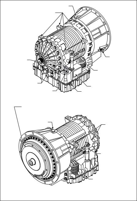
Figure 1. Typical 3000 MH Series Transmission
(WTEC III Controls)
8
BREATHER |
|
ASSEMBLY PADS |
|
OUTPUT |
INPUT |
SPEED |
|
SPEED |
SENSOR |
SENSOR |
|
|
FILL TUBE |
|
AND DIPSTICK |
|
(Available on |
|
both sides) |
COOLER PORTS |
NAMEPLATE |
NOTE: Inch Series Threads |
|
FEEDTHROUGH |
MAIN-PRESSURE TAP |
HARNESS CONNECTOR |
NOTE: Inch Series Threads |
TORQUE CONVERTER |
|
WITH LOCKUP CLUTCH |
|
AND TORSIONAL DAMPER |
|
BREATHER |
ASSEMBLY |
|
|
|
PADS |
|
(BOTH SIDES) |
|
FILL TUBE |
|
AND DIPSTICK |
|
(Available on |
|
both sides) |
|
MAIN-PRESSURE TAP |
|
NOTE: Inch Series Threads |
|
V06341.03.01 |
Figure 2. Typical 3000 MH Series Transmission (Allison 4 th Generation Controls)
9
BREATHER
FEEDTHROUGH
HARNESS
CONNECTOR
OUTPUT SPEED
SENSOR
COOLER PORTS
MOUNTING PAD (BOTH SIDES)
MAIN-PRESSURE TAP 
 MOUNTING
PAD
 INPUT SPEED
SENSOR
TURBINE SPEED
SENSOR
FILL TUBE AND DIPSTICK
NAMEPLATE
BREATHER
FEEDTHROUGH
HARNESS
CONNECTOR
COOLER PORTS
V06342
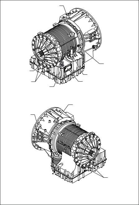
Figure 3. Typical 4000 MH Series Transmission
(WTEC III Controls)
10
BREATHER
OUTPUT SPEED
SENSOR
COOLER PORTS
FEEDTHROUGH HARNESS CONNECTOR
MOUNTING PAD (BOTH SIDES)
MAIN-PRESSURE TAP 

 MOUNTING
PAD
 INPUT SPEED
SENSOR
TURBINE SPEED
SENSOR
FILL TUBE AND DIPSTICK
NAMEPLATE
BREATHER
COOLER PORTS
V06342.01.00
Figure 4. Typical 4000 MH Series Transmission (Allison 4 th Generation Controls)
11
A BRIEF DESCRIPTION OF THE ALLISON MOTORHOME SERIES TRANSMISSIONS
Included in the Allison On-Highway Transmission family are the Motorhome Series transmissions. The transmissions described in this manual include:
•WTEC III Controls or Allison 4th Generation Controls
•A torque converter with lockup and torsion damper
•Three planetary gear sets
Motorhome Series transmissions may contain an integral retarder or a provision to mount a Power Takeoff (PTO).
ELECTRONIC CONTROL SYSTEM
All Motorhome Series transmissions come standard with WTEC III Controls or Allison 4th Generation Controls. These systems consist of five major components connected by OEM-furnished wiring harnesses. The five major components are:
•Transmission Control Module (TCM) or Electronic Control Unit (ECU)
•Three speed sensors
•Remote shift selector
•Control module (which contains solenoid valves, a pressure switch, and an optional oil level sensor)
•Engine Electronic Control Module (ECM) or Engine Throttle Position Sensor (TPS), if installed
The TCM/ECU receives information from the following:
•Throttle position sensor, if installed
•Speed sensors
•Pressure switch
•Shift selector
The TCM/ECU processes information and then sends signals to actuate specific solenoids located in the control valve module. These solenoids control both oncoming and offgoing clutch pressures to provide closed-loop shift control by matching input rpm during a shift to a desired profile programmed into the TCM/ECU.
12
A feature of both Allison 4th Generation Controls and WTEC III controls is “autodetect.” Autodetect is active within the first several engine starts, depending upon the component or sensor being detected. These engine start cycles begin when the transmission is installed during vehicle manufacture. Autodetect searches for the presence of the following transmission components or data inputs:
Transmission Components
Retarder |
Present, Not Present |
Oil Level Sensor (OLS) |
Present, Not Present |
Throttle |
Analog, J1587, J1939 |
Engine Coolant Temperature |
Analog, J1939, J1587 |
|
|
Seek help from the nearest Allison Transmission service outlet when any of the above components are present, but are not responding properly.
Another feature of the Motorhome Series transmission is its ability to adapt or “learn” as it operates. Each shift is measured electronically, stored, and used by the TCM/ECU to adapt or “learn” the optimum control for future shifts.
NOTE: Allison 4th Generation Controls and WTEC III Controls are designed and manufactured to comply with all FCC and other guidelines regarding radio frequency interference/electromagnetic interference (RFI/EMI) for transportation electronics. Manufacturers, assemblers, and installers of radio-telephone or other two-way communication radios have the sole responsibility to correctly install and integrate those devices into Allison Motorhome Series transmission-equipped vehicles to customer satisfaction.
The TCM/ECU is programmed to provide the most suitable operating characteristics for a specific application. This manual does not attempt to describe all of the possible combinations. The information contained herein describes only the operating characteristics most frequently requested by the vehicle manufacturer.
TORQUE CONVERTER
The torque converter consists of the following four elements:
•Pump—input element driven directly by the engine
•Turbine—output element hydraulically driven by the pump
•Stator—reaction (torque multiplying) element
•Lockup Clutch—mechanically couples the pump and turbine when engaged; controlled by TCM/ECU
13
When the pump turns faster than the turbine, the torque converter is multiplying torque. When the turbine approaches the speed of the pump, the stator starts to rotate with the pump and turbine. When this occurs, torque multiplication stops and the torque converter functions as a fluid coupling.
The lockup clutch is located inside the torque converter and consists of the following elements:
•Piston and backplate—driven by the engine
•Clutch plate/damper (located between the piston and the backplate)—splined to the converter turbine
The lockup clutch/torsional damper is engaged and released in response to electronic signals from the TCM/ECU. Lockup clutch engagement provides a direct drive from the engine to the transmission gearing. This eliminates converter slippage and maximizes fuel economy and vehicle speed. The lockup clutch releases at lower speeds or when the TCM/ECU detects conditions requiring it to be released.
The torsional damper absorbs engine torsional vibration to prevent transmitting vibrations through the powertrain.
PLANETARY GEARS AND CLUTCHES
A series of three helical planetary gear sets and shafts provides the mechanical gear ratios and direction of travel for the vehicle. The planetary gear sets are controlled by five multiplate clutches that work in pairs to produce up to six forward speeds and one reverse speed. The clutches are applied and released hydraulically in response to electronic signals from the TCM/ECU to the appropriate solenoids.
COOLER CIRCUIT
The transmission fluid is cooled by an integral (transmission-mounted) or remote-mounted oil cooler. Connections to the cooling circuit are located at the front or rear of the transmission to facilitate installation of remote cooler lines. On retarder models, only the rear cooler ports may be used. The integral cooler is mounted on the lower rear portion of the transmission, replacing the remote cooler manifold. Integral cooler oil ports are internal requiring coolant to be routed to and from the cooler.
A new feature has been added on all retarder-equipped transmissions. The retarder housing now allows addition of either a remote or integral cooler for transmission sump fluid in addition to retarder out fluid. A by-pass cover is placed over the sump cooling ports when the provision is not used. The sump cooler ports are located on the lower right rear face of the retarder housing (refer to Figure 1 through Figure 4).
14
RETARDER
The self-contained retarder is at the output of the transmission and consists of a vaned rotor which rotates in a vaned cavity. The rotor is splined to and driven by the output shaft. An external accumulator holds transmission fluid until the retarder is activated. When the retarder is activated, the fluid in the accumulator is pressurized by the vehicle air system and directed into the retarder cavity. The interaction of the fluid with the rotating and stationary vanes causes the retarder rotor and output shaft to reduce speed, slowing the vehicle or limiting speed on a downhill grade. Refer to USING THE HYDRAULIC RETARDER for additional information.
When the retarder is deactivated, the retarder cavity is evacuated and the accumulator is recharged with fluid.
15
SHIFT SELECTORS
DESCRIPTION OF AVAILABLE TYPES
|
HOLD OVERRIDE BUTTON |
|
HOLD OVERRIDE |
|
|
|
|
|
MODE INDICATOR |
|
BUTTON |
|
|
|
|
|
MODE INDICATOR |
|
|
|
|
|
(LED) |
|
|
|
|
|
|
|
(LED) |
|
|
|
|
|
MODE BUTTON |
|
|
R |
|
1 |
|
R |
|
|
||
MODE |
|
MODE |
|
|
MODE |
|
2 |
|
|
N |
MODE BUTTON |
|
N |
3 |
|
|
D |
|
D |
|
4 |
|
MODE ID |
5 |
MODE ID |
|
5 |
|
|
4 |
||||
5 |
|
|
4 |
DIGITAL DISPLAY* |
|
3 |
D |
DIGITAL DISPLAY* |
3 |
|
|||
|
1 |
|||||
N |
2 |
|
||||
|
|
|
|
|
|
2 |
R |
|
|
1 |
|
|
|
|
|
DISPLAY MODE/ |
|
DISPLAY MODE/ |
|
|
|
|
|
DIAGNOSTIC BUTTON |
|
|
|
|
DIAGNOSTIC BUTTON |
|
|
|
||
SIX-SPEED, |
|
|
|
|
||
|
SIX-SPEED, |
CONTOURED |
||||
LEFT-HAND |
|
RIGHT-HAND |
||||
|
|
VERSION |
||||
LEVER |
|
LEVER SELECTOR |
||||
|
|
|
||||
SELECTOR |
|
WITH REVERSE TO FRONT |
|
|
||
|
|
DIGITAL DISPLAY* |
|
|
|
|
|
|
MODE ID |
|
|
|
|
|
|
MODE |
|
R MODE |
|
|
R |
MODE |
INDICATOR (LED) |
|
|
|
|
|
|
|
|
|||
N |
|
Push simultaneously |
|
N |
|
|
|
|
D |
|
|
||
D |
|
to enter diagnostic |
|
|
|
|
|
|
|
|
|
||
|
mode and fluid |
|
|
|
|
|
|
|
|
|
|
|
|
|
|
level check |
|
|
|
|
|
|
PUSHBUTTON SELECTORS |
|
|
||
*NOTE: Number displayed is highest forward range available in selected position. |
|
|
||||
Visually check to confirm range selected. If display is flashing, shift is inhibited. |
V07343.01.02 |
|||||
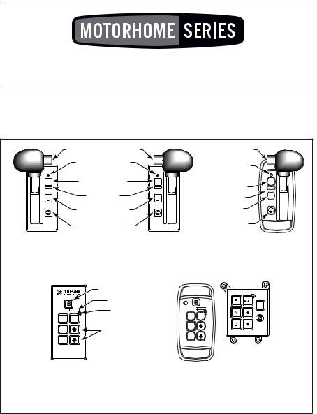
Figure 5. WTEC III Shift Selectors
16
|
HOLD OVERRIDE |
|
HOLD OVERRIDE |
|
|
|
BUTTON |
|
BUTTON |
|
|
|
MODE INDICATOR |
|
MODE INDICATOR |
|
|
|
(LED) |
|
|
||
|
|
(LED) |
|
||
|
MODE BUTTON |
|
|
||
|
|
MODE BUTTON |
|
||
6 |
|
6 |
6 |
||
MODE ID |
MODE ID |
||||
1 |
1 |
1 |
|||
|
DIGITAL DISPLAY* |
|
DIGITAL DISPLAY* |
|
|
|
DISPLAY MODE |
|
DISPLAY MODE |
|
|
|
DIAGNOSTIC BUTTON |
|
DIAGNOSTIC BUTTON |
|
DIGITAL DISPLAY*
MODE ID
|
MODE |
6 |
|
1 |
|
MODE |
INDICATOR (LED) |
|
|
|
 Push simultaneously
to enter diagnostic mode and fluid level check
*NOTE: The first number displayed is highest forward range available and second number is range attained in selected position.
Visually check to confirm range selected. If display is flashing, shift is inhibited. |
V07343.03.01 |
Figure 6. Allison 4th Generation Controls Shift Selectors
INTRODUCTION
Vehicle manufacturers may choose different types of shift selectors for their vehicles. The shift selector in your Allison-equipped vehicle will be similar to one of the pushbutton or lever styles shown above.
With an Allison-equipped vehicle, it is not necessary to select the right moment to upshift or downshift during changing road and traffic conditions. The Allison Motorhome Series transmission does it for you. However, knowledge of the shift selector positions, available ranges, and when to select them, make vehicle control and your job even easier. Select lower ranges when descending long grades (with or without retarder) to reduce wear on service brakes. Refer to the Range Selection table at the end of this section for related information.
17

LEVER SHIFT SELECTOR
General Description. The lever shift selector (refer to Figure 5 and Figure 6) is an electro-mechanical control. Typical lever positions are:
•R (Reverse)
•N (Neutral)
•D (Drive)
•Some number of lower forward range positions
Motorhome Series transmissions can be programmed to have four, five, or six forward ranges. Shift selector positions should agree with the programming of the TCM/ECU unit.
The lever selector includes the following:
•HOLD OVERRIDE button
•MODE button
•Digital display
•DISPLAY MODE/DIAGNOSTIC button
HOLD OVERRIDE Button. The lever shift selector has three locked positions to prevent accidentally selecting R (Reverse), N (Neutral), or D (Drive). Select
R (Reverse), N (Neutral), or D (Drive) by pressing the HOLD OVERRIDE button and moving the lever to the desired position. Once D (Drive) is selected, lower forward range positions may be selected without pressing the
HOLD OVERRIDE button.
MODE Button. The MODE button can allow the driver to enable a secondary shift schedule, PTO, or other special functions that have been programmed into the TCM/ECU unit at the request of the OEM. For example, a motorhome OEM may have provided a secondary shift schedule for improved fuel economy. The name of the special function (ECONOMY) appears on the MODE ID label adjacent to the MODE button. Pressing the MODE button activates the ECONOMY shift schedule and illuminates the MODE INDICATOR (LED).
When the Diagnostic Display Mode has been entered, the MODE button is used to view and toggle through diagnostic code information. After viewing the first diagnostic code which appears in the digital display, press the MODE button to view the 2nd diagnostic code logged. Repeat this procedure to view the 3rd, 4th, and 5th code positions. The code displayed is active if the MODE INDICATOR (LED) is illuminated.
NOTE: Visually check the digital display whenever the lever is moved to be sure the range selected is shown. N should appear in the digital display if the N (Neutral) button is pressed.
18
Digital Display. During normal operation, if D (Drive) is selected, the digital display shows the highest forward range attainable for the shift schedule in use.
Abnormal operation is indicated by the WTEC III digital display as follows:
•When all segments of the digital display are illuminated for more than 12 seconds, the ECU did not complete initialization.
•When the digital display is blank, there is no power to the selector.
•When the display shows a “\/\” (cateye), a selector-related fault code has been logged.
•Conditions which illuminate the CHECK TRANS light disable the shift selector and the digital display displays the range actually attained. For a detailed explanation, refer to the CHECK TRANS LIGHT paragraph in the DRIVING TIPS section.
Abnormal operation is indicated by the Allison 4th Generation Controls digital display as follows:
•When all segments of the digital display are illuminated, the shift selector did not complete initialization.
•When both digital displays remain blank for 10 seconds after initialization and then show a “\/\” (cateye), the shift selector is unable to communicate with the TCM or has experienced an internal fault.
•When the display shows a “\/\” (cateye), a selector-related fault code has been logged.
•Conditions which illuminate the CHECK TRANS light disable the shift selector. The SELECT digit is blank and the MONITOR digit displays the range actually attained. For a detailed explanation, refer to the CHECK TRANS LIGHT paragraph in the DRIVING TIPS section.
The transmission will not shift into range if a CHECK TRANS code is active. When the display shows R or D has been requested and the display is flashing, the requested range has not been achieved due to an inhibit function.
Some inhibit functions are vehicle-related and do not result in diagnostic codes. Some examples are mentioned in the Range Selection tables at the end of this Section.
Check for active codes if no other inhibit function has been located. Once
D (Drive) is attained, the transmission will shift into the lowest range programmed for the D (Drive) position, usually first-range.
Display Mode/Diagnostic Button. The DISPLAY MODE/DIAGNOSTIC button allows access to optional fluid level check information and diagnostic code information. Press the DISPLAY MODE/DIAGNOSTIC button once to obtain transmission fluid level information and a second time to obtain diagnostic code information.
19
PUSHBUTTON SHIFT SELECTOR
General Description. The pushbutton shift selector (refer to Figure 5 and Figure 6) has the following:
•R (Reverse)—Press this button to select Reverse.
•N (Neutral)—Press this button to select Neutral.
•D (Drive)—Press this button to select Drive. The highest forward range available will appear in the digital display window. The transmission will start out in the lowest available forward range and advance automatically to the highest range.
•↑ (Up) Arrow—Press the ↑ (Up) Arrow when in DRIVE to request the next higher range. Continuously pressing the ↑ (Up) Arrow will request the highest range available.
•↓ (Down) Arrow—Press the ↓ (Down) Arrow when in DRIVE to request the next lower range. Continuously pressing the ↓ (Down) Arrow will request the lowest range available.
•MODE Button and Display Mode/Diagnostic Button—This is the same function as described previously in the LEVER SHIFT SELECTOR paragraph, MODE Button paragraph.
NOTE: The oil level sensor is a standard feature on Motorhome Series transmissions. Fluid level information is displayed after pressing both the ↑ (Up) and ↓ (Down) arrow buttons simultaneously. Simultaneously press both buttons again to obtain diagnostic data.
Refer to the Care And Maintenance section, FLUID LEVEL CHECK USING PUSHBUTTON OR LEVER SHIFT SELECTOR for more information about fluid level data. Refer to the Driving Tips section, DIAGNOSTIC CODES and DIAGNOSTIC CODE DISPLAY PROCEDURE, for more information about diagnostic codes and display procedure.
20
RANGE SELECTION
|
|
R |
R |
|
|
|
MODE |
||
|
|
MODE |
N |
|
|
R |
N |
D |
|
R MODE |
MODE |
|||
D |
5 |
|||
N |
N |
5 |
4 |
|
4 |
3 |
|||
|
||||
|
D |
3 |
2 |
|
D |
2 |
1 |
||
|
||||
|
1 |
|
||
|
|
|
V07344
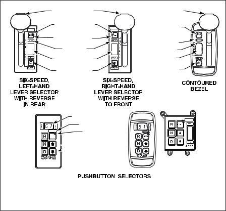
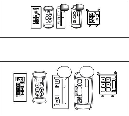
Figure 7. Typical Motorhome Series Shift Selectors
(WTEC III Controls)
MODE
6
1
R
N
D
5
4
3
2
1
6
1 6 


1
V07344.01.00
Figure 8. Typical Motorhome Series Shift Selectors (Allison 4 th Generation Controls)
21
PUSHBUTTON AND LEVER SHIFT SELECTORS
WITH DIGITAL DISPLAY
Description of Available Ranges (refer to Figure 7 and Figure 8)
WARNING: If you leave the vehicle and the engine is running, the vehicle can move unexpectedly and you or others could be injured. If you must leave the engine running, do not leave the vehicle until you have completed all of the following procedures:
1.Put the transmission in N (Neutral).
2.Be sure the engine is at low idle (500–800 rpm).
3.Apply the parking brakes and emergency brake and make sure they are properly engaged.
4.Chock the wheels and take any other steps necessary to keep the vehicle from moving.
WARNING: R (Reverse) may not be attained due to an active inhibitor. Always apply the service brakes when selecting
R (Reverse) to prevent unexpected vehicle movement and because a service brake inhibit may be present. When “R” is flashing, it indicates the shift to R (Reverse) is inhibited. Check for active diagnostic codes if R (Reverse) is not attained. See DOWNSHIFT AND DIRECTION CHANGE INHIBITOR FEATURE in the DRIVING TIPS section.
CAUTION: Do not idle in R (Reverse) for more than five minutes. Extended idling in R (Reverse) can cause
transmission overheating and damage. Always select N (Neutral) whenever time at idle exceeds five minutes.
NOTE: Visually check the digital display window whenever a button is pushed or the lever is moved to be sure the range selected is shown (i.e., if the N (Neutral) button is pressed, “N” should appear in the digital display). A flashing display indicates the range selected was not attained due to an active inhibit.
22
PUSHBUTTON AND LEVER SHIFT SELECTORS
WITH DIGITAL DISPLAY (cont’d)
Description of Available Ranges (refer to Figure 7 and Figure 8)
RCompletely stop the vehicle and let the engine return to idle before shifting from a forward range to R (Reverse) or from R (Reverse) to a forward range. The digital display will display “R” when
R (Reverse) is selected.
WARNING: When starting the engine, make sure the service brakes are applied. Failure to apply the service brakes can result in unexpected vehicle movement.
WARNING: Vehicle service brakes, parking brake, or emergency brake must be applied whenever N (Neutral) is selected to prevent unexpected vehicle movement. Selecting N (Neutral) does not apply vehicle brakes, unless an auxiliary system to apply the parking brake is installed (see the Operator’s Manual for the vehicle).
WARNING: If you let the vehicle coast in N (Neutral), there is no engine braking and you could lose control. Coasting can also cause severe transmission damage. To help avoid injury and property damage, do not allow the vehicle to coast in
N (Neutral).
NUse N (Neutral) when starting the engine, to check vehicle accessories, and for extended periods of engine idle operation (longer than five minutes). For vehicles equipped with the pushbutton selector, N (Neutral) is selected by the ECU during start-up. For vehicles equipped with the lever selector, the vehicle will not start unless N (Neutral) has been selected. If the vehicle starts in any range other than N (Neutral), seek service immediately. N (Neutral) is also used during stationary operation of the power takeoff (if the vehicle is equipped with a PTO). The digital display will show “N” when N (Neutral) is selected. Always select N (Neutral) before turning off the vehicle engine.
23
PUSHBUTTON AND LEVER SHIFT SELECTORS
WITH DIGITAL DISPLAY (cont’d)
Description of Available Ranges (refer to Figure 7 and Figure 8)
WARNING: D (Drive) may not be attained due to an active inhibitor. Always apply the service brakes when selecting
D (Drive) to prevent unexpected vehicle movement and because a service inhibit may be present. When “D” is flashing, it indicates the shift to D (Drive) is inhibited. Check for active diagnostic codes if D (Drive) is not attained. See DOWNSHIFT AND DIRECTION CHANGE INHIBITOR FEATURE in the DRIVING TIPS section.
CAUTION: Do not idle in D (Drive) or any forward range for more than five minutes. Extended idling in D (Drive) can cause transmission overheating and damage. Always select N (Neutral) whenever time at idle exceeds five minutes.
NOTE: Turn off the vehicle HIGH IDLE switch, if present, before shifting from N (Neutral) to D (Drive) or R (Reverse). D (Drive) or R (Reverse) will not be attained unless the shift is made with the engine at idle. Also, be aware of other interlocks that would prevent attaining D (Drive) or R (Reverse). Examples are “wheelchair lift not stored” and “service brakes not applied” (service brake interlock present).
DThe transmission will initially attain first-range when D (Drive) is selected (except for those units programmed to start in second-range). As vehicle speed increases, the transmission will upshift automatically through each range. As the vehicle slows, the transmission will downshift automatically through each range. The digital display will show the highest range available in D (Drive).
WARNING: The transmission incorporates a hold feature to prohibit upshifting above the range selected during normal driving. For downhill operation, select a lower transmission range. If the engine governed speed is exceeded in the held range, however, the transmission will upshift to the next higher range to prevent engine damage. To avoid injury and/or property damage due to loss of vehicle control, use the vehicle brakes to prevent exceeding engine governed speed in the held range.
24

|
PUSHBUTTON AND LEVER SHIFT SELECTORS |
|
WITH DIGITAL DISPLAY (cont’d) |
|
|
Description of Available Ranges (refer to Figure 7 and Figure 8) |
|
6* |
Lower ranges provide greater engine braking for going down |
5* |
grades (the lower the range, the greater the braking effect). |
4* |
Occasionally, it may be desirable to restrict automatic shifting to a |
3 |
lower range because of: |
2 |
• Road conditions. |
|
• Load. |
|
• Traffic conditions. |
|
• Etc. |
|
The pushbutton shift selector arrow buttons access individual |
|
forward ranges. Push the ↑ (Up) or ↓ (Down) arrow for the desired |
|
range. The digital display shows the range chosen. Even though a |
|
lower range is selected, the transmission may not downshift until |
|
vehicle speed is reduced (this prevents excessive engine speed in |
|
the lower range). |
1 |
First-range provides the vehicle with its maximum driving torque |
|
and engine braking effect. Use first-range when: |
|
• Pulling through mud and deep snow. |
|
• Maneuvering in tight spaces. |
|
• Driving up or down steep grades. |
|
For vehicles equipped with the pushbutton selector, push the |
|
↓ (Down) arrow until first-range appears in the select window. |
* Actual ranges available depend on programming by vehicle manufacturer.
25
DRIVING TIPS
CHECK TRANS LIGHT
The electronic control system is programmed to inform the operator of a problem with the transmission system and automatically take action to protect the operator, vehicle, and transmission. When the Electronic Control Unit (ECU) or the Transmission Control Module (TCM) detects a problem condition, the TCM/ECU:
•Restricts shifting.
•Illuminates the CHECK TRANS light on the instrument panel.
•Registers a diagnostic code.
NOTE: For some problems, diagnostic codes may be registered without the TCM/ECU activating the CHECK TRANS light. Your Allison Transmission authorized service outlet should be consulted whenever there is a transmission-related concern. They have the equipment to check for diagnostic codes and to correct problems which arise.
Each time the engine is started, the CHECK TRANS light will illuminate, then turn off after a few seconds. This momentary lighting is to show that the status light circuits are working properly. If the CHECK TRANS light does not illuminate during ignition, or if the light remains on after ignition, the system should be checked immediately.
Continued illumination of the CHECK TRANS light during vehicle operation (other than start-up) indicates that the TCM/ECU has signaled a diagnostic code. Illumination of the CHECK TRANS light is accompanied by a flashing display from the shift selector. The shift selector display will show the actual range attained and the transmission will not respond to shift selector requests.
Indications from the shift selector are provided to inform the operator the transmission is not performing as designed and is operating in the “limp home” mode with reduced capabilities. Before turning off the ignition, the transmission may be operated for a short time in the selected range in order to “limp home” for
26

service assistance. Service should be performed immediately in order to minimize the potential for damage to the transmission.
When the CHECK TRANS light comes on and the ignition switch is turned off, the transmission will remain in N (Neutral) until the condition causing the CHECK TRANS light is corrected.
Generally, while the CHECK TRANS light is on, upshifts and downshifts will be restricted and direction changes will not occur. Lever and pushbutton shift selectors do not respond to any operator shift requests while the CHECK TRANS light is illuminated. The lockup clutch is disengaged when transmission shifting is restricted or during any critical transmission malfunction.
DIAGNOSTIC CODES
See detailed information in the DIAGNOSTICS section.
ACCELERATOR CONTROL
WARNING: To help avoid injury or property damage caused by sudden movement of the vehicle, do not make shifts from N (Neutral) to
D (Drive) or R (Reverse) when the throttle pedal is depressed. If you shift while the throttle pedal is depressed too far, the transmission will only engage if the throttle pedal is released in the next three seconds.
This may cause a sudden movement of the vehicle. Leaving the throttle pedal depressed longer than three seconds causes the transmission to remain in N (Neutral). Avoid this condition by making shifts from
N (Neutral) to D (Drive) or R (Reverse) only when the throttle is closed.
The position of the accelerator pedal influences when automatic shifting occurs. An electronic throttle position signal tells the TCM/ECU how much the operator has depressed the pedal. When the pedal is fully depressed, upshifts will occur automatically at high engine speeds. A partially depressed position of the pedal will cause upshifts to occur at lower engine speeds. Excessive throttle position affects directional changes—shifts from N (Neutral) to D (Drive) or R (Reverse).
DOWNSHIFT AND DIRECTION CHANGE INHIBITOR FEATURE
NOTE: Turn off the vehicle HIGH IDLE switch, if present, before shifting from N (Neutral) to D (Drive) or R (Reverse). The shift from N (Neutral) to D (Drive) or R (Reverse) is inhibited when engine speed is above idle.
27
There is no speed limitation on upshifting, but there is a limitation on downshifting and for shifts that cause a direction change such as
D (Drive)-to-R (Reverse) or R (Reverse)-to-D (Drive).
Manual range downshifts will not occur until a calibration output speed (preset) is reached. When a range downshift is manually selected and the transmission output speed is above the calibration speed, the transmission will stay in the range it was in even though a lower range was requested. Apply the vehicle service brakes or a retarding device to reduce the transmission output speed to the calibration speed and then the shift to the lower range will occur.
Directional shifts, D (Drive)-to-R (Reverse) or R (Reverse)-to-D (Drive), will not occur if selected when throttle position, engine speed, or transmission output speed is above the calibration limit for a calibration time period. The current calibration time period for engine speed is 0.5 seconds and for throttle position and output speed is three seconds.
Shifts from N (Neutral)-to-D (Drive) or N (Neutral)-to-R (Reverse) are also inhibited when the TCM/ECU has been programmed (by input/output function) to detect that auxiliary equipment is in operation and the shift should not be allowed.
When directional change shifts are inhibited, the TCM/ECU will put the transmission in N (Neutral) and the digital display, if present, will flash the letter of the range selected (D or R). To reselect D (Drive) or R (Reverse) when engine throttle, engine speed, and transmission output speed are below the calibration value:
•Pushbutton selector—Press the desired pushbutton again.
•Lever selector—Move the lever to N (Neutral) and then to the desired range.
When a direction change shift is requested and engine throttle, engine speed, and transmission output speed drop below the calibration value during the calibration time interval, the shift to D (Drive) or R (Reverse) will occur.
For example, if the transmission output speed was just above the calibration limit when R (Reverse) was selected, but dropped below the limit during the next three seconds, the shift to R (Reverse) would occur (assuming the engine was at idle and the throttle was closed).
28
 Loading...