

Page 1

- 1 -
Service Manual
Model: P42L6A-T1
Specifications & Design are subject to change without notice.
Page 2

- 2 -
Contents
1. Contents……………………………………………………………...1
2. Features……………………………………………………………...2
3. Safety Precautions………………………………………................3
4. Photo of PDP taking apart…………………………….……………6
5. PANEL Part…………………………………………………………..8
a. Adjustment……………………………………………………….8
b. Trouble Shooting………………………………………………10
c. Power specification……………………………………………20
6. Introduction to PDP circuit boards………………………………..23
a: Signal flow-chart………………………………………………23
b: CHIP SUMMARY……………………………………………..24
c: Debug flow-chart………………………………………………25
7. Circuit Drawing……………………………………………………..26
Page 3

- 3 -
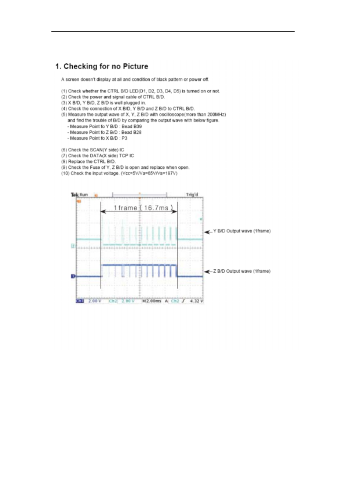
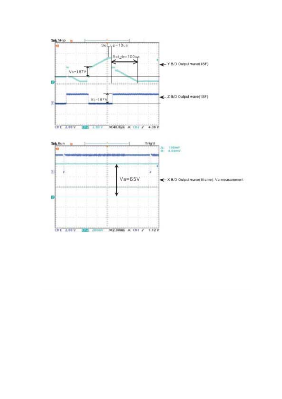
1. Features
The 42” PDP provides quality image displays and is suitable for a variety of
multimedia applications.
a. Available Input signals:
The Digital module provides RGB (D-SUB15 PIN) and digital DVI input
connectors, and component video (RCA) input connectors. It supports
the quality input image of DVD and HDTV (480P/720P/1080i/1080P).
The analogue module provides composite video (RCA), S-video
(DIN4P), The analogue module also provides one set of stereo audio
input connectors (RCA).
The product supports PC image resolutions up to XGA (1024х768)
with a vertical frequency of 75HZ.
RF terminal,you can watch TV expediently,The format contain
PAL-M/N,NTSC-M
b. General specification
Model name: P42L6A-T1(H)
Number of pixel:1024(H)×768(V) (1Pixel=3RGB Cells)
Display area : 920.1(H) x 518.4(V)±0.5mm
Color arrangement : RGB Closed type
Number of COLRO : (R)1024 x (G)1024 x (B)1024
Aspect Ratio : 16:9
Peak Brightness : Typical 1200dc/ (1/100 White Window)
Contrast Ratio : Typical 10000:1(Dark room 1/100 White Window)
(White Window Pattern at Center)
POWER CONSUMPTION : Typical 320 W(Full White)
Available voltage range:AC110V~240V
Frequency range:50~60HZ(±3HZ)
Page 4

- 4 -
2. Safety Precautions
When servicing of PDP Module, it should be not enforced into another way
aside next rule, or a unaccustomed person should not repairing. When
using/handling this PDP Module, pay attention to the below warning and
cautions.
Warning
Indicates a hazard that may lead to death or injury if the warning is ignored
and the product is handled incorrectly.
Caution
Indicates a hazard that can lead to injury or damage to property if the
caution is ignored and the product is handled incorrectly.
1) WARNING
(1) Do not touch Signal and Power Connector while this product operates.
Do not touch EMI ground part and Heat Sink of Film Filter.
(2) Do not supply a voltage higher than that specified to this product. This may
damage the product and may cause a fire.
(3) Do not use this product in locations where the humidity is extremely high,
where it may be splashed with water, or where flammable materials surround
it.
Do not install or use the product in a location that does no satisfy the specified
environmental conditions. This may damage the product and may cause a fire.
(4) If a foreign substance (such as water, metal, or liquid) gets
inside the product, immediately turn off the power.
Continuing to use the product, it is may cause fire or electric shock.
(5) If the product emits smoke, and abnormal smell, or makes
an abnormal sound, immediately turn off the power.
Continuing to use the product, it may cause fire or electric shock.
(6) Do not disconnect or connect the connector while power to the product is
on. It takes some time for the voltage to drop to a sufficiently low level after the
power has been turned off.
Confirm that the voltage has dropped to a safe level before disconnecting or
connecting the connector.
(7) Do not pull out or insert the power cable from/to an outlet with wet hands. It
may cause electric shock.
(8) Do not damage or modify the power cable. It may cause fire or electric
shock.
(9) If the power cable is damaged, or if the connector is loose, do not use the
product: otherwise, this can lead to fire or electric shock.
(10) If the power connector or the connector of the power cable becomes dirty
or dusty, wipe it with a dry cloth.0therwise, this can lead to fire.
(11) PDP Module uses a high voltage (Max.450V dc). Keep the cautions
concerning electric shock and do not touch the Device circuitry when handling
the PDP Unit. And because the capacitor of the Device circuitry may remain
Page 5

- 5 -
charged at the moment of Power OFF, standing by for 1 minute is required in
order to touch the Device circuitry.
2) CAUTIONS
(1) Do not place this product in a location that is subject to heavy vibration, or
on an unstable surface such as an inclined surface. The product may fall off or
fall over causing injuries.
(2) Before disconnecting cable from the product, be sure to turn off the power.
Be sure to hold the connector when disconnecting cables. Pulling a cable with
excessive force may cause the core of the cable to be exposed or break the
cable, and this can lead to fire or electric shock.
(3) This product should be moved by two or more persons. If one person
attempts to carry this product alone, he/she may be injured.
(4) This product contains glass. The glass may break, causing injuries, if shock,
vibration, heat, or distortion is applied to the product.
(5) The temperature of the glass of the display may rise to 80°C or more
depending on the conditions of use If you touch the glass inadvertently, you
may be burned.
(6) If glass surface of the display breaks or is scratched, do not touch the
broken pieces or the scratches with bare hands. You may be injured.
(7) PDP Module requires to be handled with care not to be touched with metal
or hard materials, and must not be stressed by heat or mechanical impact.
(8) There are some exposed components on the rear panel of this product.
Touching these components may cause an electric shock.
(9) When moving the product, be sure to turn off the power and disconnect all
the cables. While moving the product, watch your step. The product may be
dropped or all leading to injuries of electric shock.
(10) In order to protect static electricity due to C-MOS circuitry of
the Drive part, wear a wrist band to protect static electricity
when handling.
(11) If cleaning the Panel, wipe it with a soft cloth moistened with water or a
neutral detergent and squeezed, being careful not to touch the connector part
of the Panel. And don’t use chemical materials like thinner or benzene.
(12) If this product is used as a display board to display a static image, “image
sticking” occurs. This means that the luminance of areas of the display that
remain lit for a long time drops compared with luminance of areas that are lit for
a shorter time, causing uneven luminance across the display The degree to
which this occurs is in proportion to the luminance at which the display is used.
To prevent this phenomenon, therefore, avoid static images as much as
possible and design your system so that it is used at a low luminance, by
reducing signal level difference between bright area and less bright area
through signal processing.
(13) Because PDP Module emits heat from the Glass Panel part and the Drive
circuitry, the environmental temperature must not be over 40°C.
The temperature of the Glass Panel part is especially high owing to heat from
Page 6

- 6 -
internal Drive circuitry. And because the PDP Module is driven by high voltage,
it must avoid conductive materials.
(14) If inserting components or circuit board in order to repair, be sure to fix a
lead line to the connector before soldering.
(15) If inserting high-power resistor (metal-oxide film resistor or metal film
resistor) in order to repair, insert it as 10mm away as from a board.
(16) During repairs, high voltage or high temperature components must be put
away from a lead line.
(17) This is a Cold Chassis but you had better use a cold transformer for safety
during repairs. If repairing electricity source part, you must use the cold
transformer.
(18) Do not place an object on the glass surface of the display. The glass may
break or be scratched.
(19) This product may be damaged if it is subject to excessive stresses (such
as excessive voltage, current, or temperature).
The absolute maximum ratings specify the limits of these stresses.
(20) The recommended operating conditions are conditions in which the
normal operation of this product is guaranteed. All the rated values of the
electrical specifications are guaranteed within these conditions.
Always use the product within the range of the recommended operating
conditions. Otherwise, the reliability of the product may be degraded.
(21) This product has a glass display surface. Design your system so that
excessive shock and load are not applied to the glass. Exercise care that the
vent at the corner of the glass panel is not damaged If the glass panel or vent
is damaged, the product is inoperable.
(22) Do not cover or wrap the product with a cloth or other covering while
power is supplied to the product.
(23) Before turning on power to the product, check the wiring of the product
and confirm that the supply voltage is within the rated voltage range. If the
wiring is wrong or if a voltage outside the rated range is applied, the product
may malfunction or be damaged.
(24) Do not store this product in a location where temperature and humidity are
high. This may cause the product to malfunction. Because this product uses a
discharge phenomenon, it may take time to light (operation may be
delayed) when the product is used after it has been stored for a long time. In
this case, it is recommended to light all cells for about 2 hours (aging).
(25) This product is made from various materials such as glass metal, and
plastic. When discarding it, be sure to contact a professional waste disposal
operator.
(26) If faults occur due to arbitrary modification or disassembly,
HAIER is not responsible for function, quality or other items.
(27) Use of the product with a combination of parameters conditions or logic
not specified in the specifications of this product is not guaranteed. If intending
to use the product in such a way, be sure to consult HAIER in advance.
Page 7
- 7 -
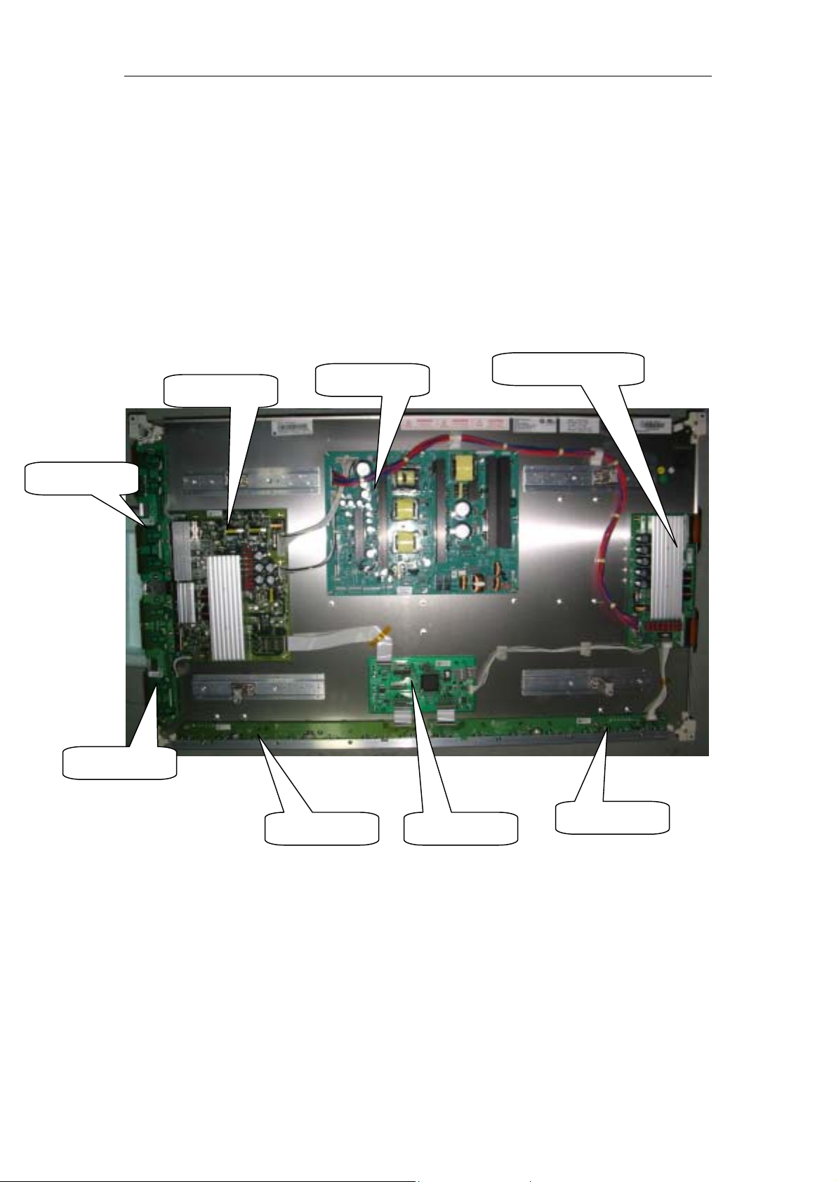
3.Photo of PDP taking apart
The introduction of circuit board at Back board:
NAME MATERIAL CODE
MODEL (PDP 42X3) 0094014444
X-SUS(left) 0094014670
X-SUS(right) 0094014671
Y-SUS 0094014672
Y-DRIVER 0094014673
Z-SUS 0094014674
CTROL BOARD 0094014675
PSU 0094014676
Y-SUS
PSU
Z-SUS
Y-DRIVER(TOP)
Y-DRIVER(BTM)
X-SUS(left)
CTROL BOARD
X-SUS(right)
Page 8
- 8 -
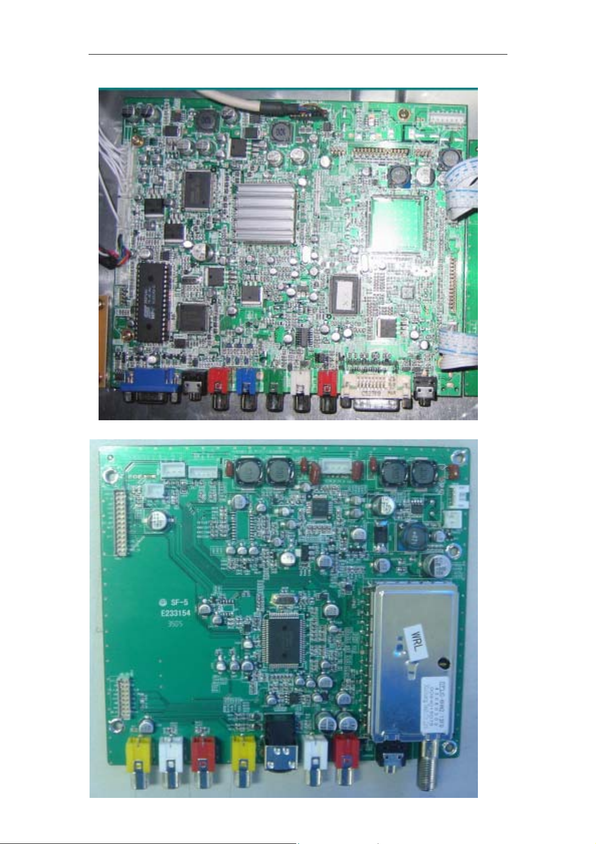
Printed Circuit Digital Board(Main Board)In bom we call it Digital board subassembly
Printed Circuit Audio Board,In bom we call it Emulation board subassembly
Page 9
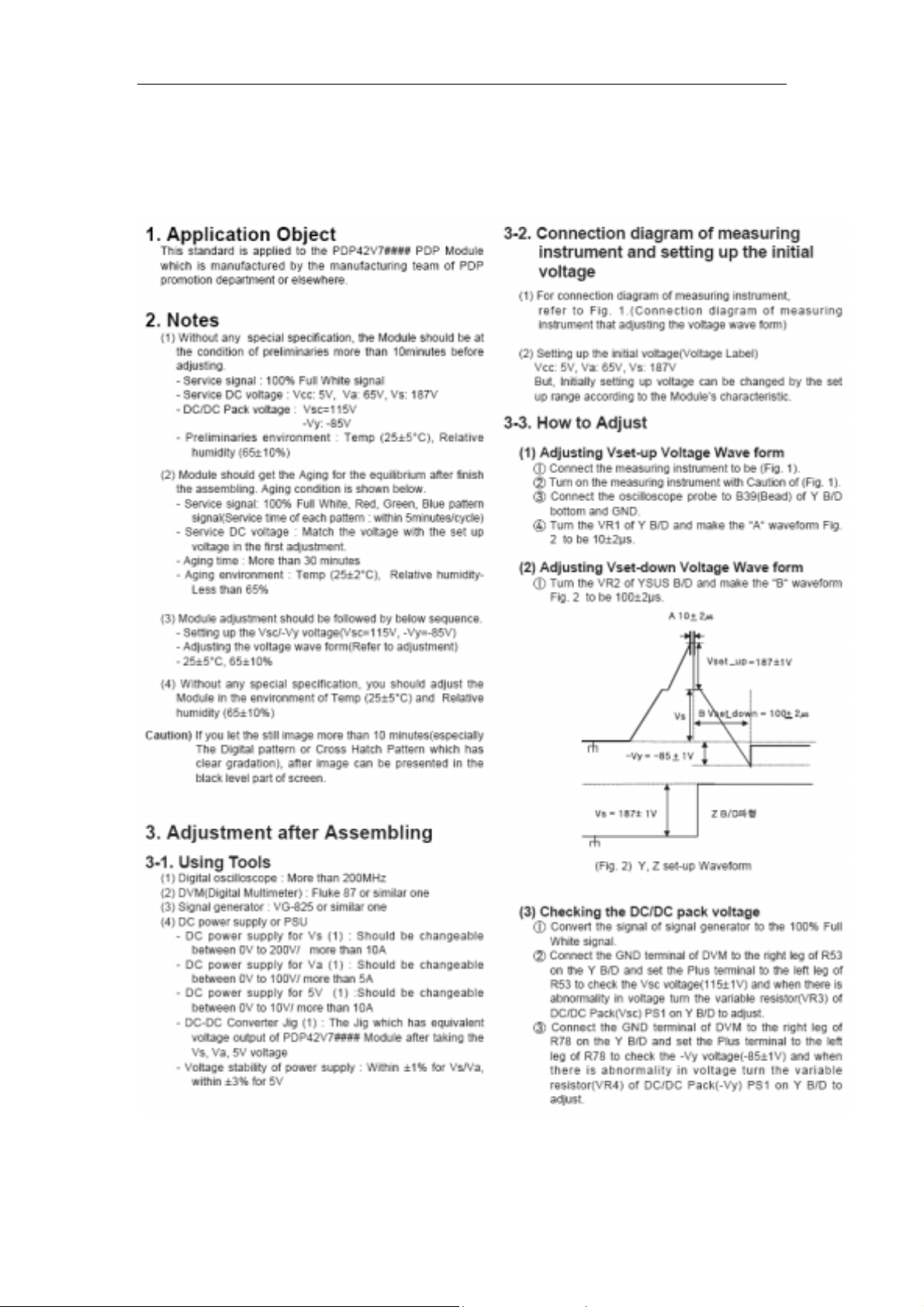
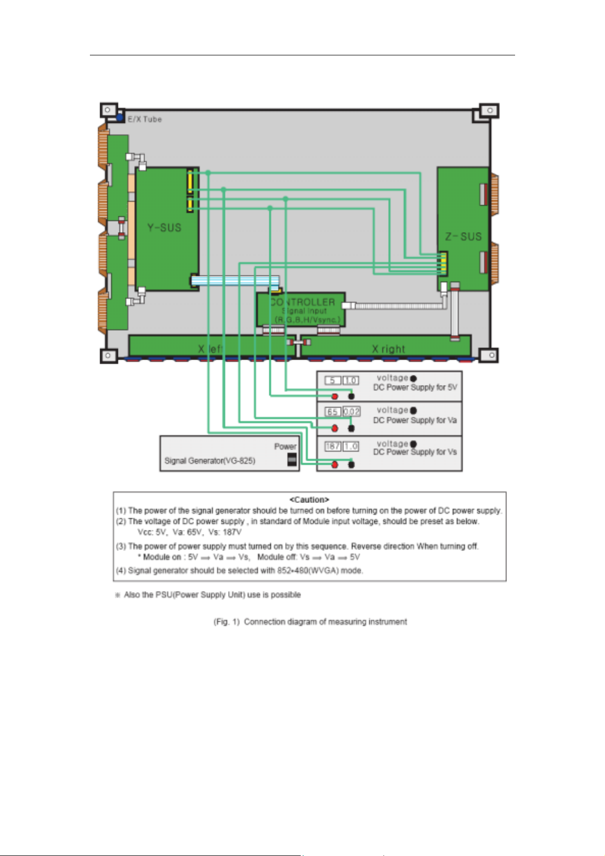
4.Panel part
a. Adjustment
- 9 -
Page 10
- 10 -
Page 11
b.Trouble shooting
- 11 -
Page 12
- 12 -
Page 13
- 13 -
Page 14
- 14 -
Page 15
- 15 -
Page 16

- 16 -
Page 17

- 17 -
Page 18

- 18 -
Page 19

- 19 -
Page 20

- 20 -
Page 21

c. Power specification
(1).Output voltage
- 21 -
(2). Micro Controller control signal
Input signal(to PSU):
RLY signal ( High : Low Voltages*1are ON Low : Low Voltages are OFF)
VS ON signal (High : High Voltages*2are ON Low : High Voltages are OFF)
Output signal(from PSU)
ACD signal (High : 75V < AC Input Voltage Low : 70V > AC Input Voltage)
5VD signal(High : Module logic Voltage*3is 5V Low : Module logic Voltage is 0V)
*1. Low Voltages : 5Vstand-by , 5Vsc, 9Vsc, 12Vsc, Vaudio
*2. High Voltages : Va, Vs
*3. Module logic Voltage : 5Vctrl
Page 22

(3).PSU ON/OFF sequence
- 22 -
Page 23

(4).PSU INPUT/OUTPUT PIN
- 23 -
Page 24

- 24 -
6. Introduction to PDP circuit boards
a: Signal flow-chart
SVIDEO_1
Component
CVBS1
4M X32
DDR
ADDRESS[18:0]
DATA[7:0]
AUDIO
SW
PC
AUDIO
MAIN
BOARD
YUV
AUDIO
Differential
Output
LVDS
Output
VIDEO
CVBS_OUT
AMP
2Vp_p
FLASH
MEMORY
TV AND
AUDIO
DECODER
TV&AUDIO
BOARD
AV
AUDIO
PC IN
DVI IN
PC RGB
PC_HS/VS
With 75 ohm
pull down
DVI
MST 3788
24-bit Data
HS, VS, CLK
SVP-EX
PQFP256
I2C
M30620SPGP
DVI
AUDIO
Page 25

- 25 -
b: CHIP SUMMARY
M30620: 16-BIT CMOS SINGLE-CHIP MICROCOMPUTER
The single-chip microcomputer operate using sophisticated instructions
featuring a high level of instruction efficiency. With 1M bytes of address space,
they are capable of executing instructions at high speed. In addition, this
microcomputer contains a multiplier and DMAC which combined with fast
instruction processing capability.
SVP-EX52: VIDEO DECODER+DE-INTERLACE+SCALE
The SVP_EX-52 video processor is a highly integrated system on a chip
device, targeting the converging HDTV-ready and PC-ready and LCD TV, PDP
TV, and DLP TV applications where high precision processing of video and
data are the requirements. SVP_EX-52 contains dual-purposed triple 10-bit
high-precision and high-speed video ADCs for both PC and video inputs, a
high performance 5th generation multi-format 3D digital comb video decoder
that supports NTSC, PAL and SECAM, an HDTV sync separator, motion
adaptive de-interlacing engine, and the video format conversion engine,
MST3788: 8-bit Analog and HDCP Interface for Advanced Digital Displays
The MST3788 integrates both analog interfaces and HDCP compliant
receivers for enabling advanced digital display devices such as digital TVs,
plasma displays, LCD TVs and projectors to receive and display. Compliant
with the HDCP 1.0 specification, the MST3788 enables consumer electronic
devices to receive uncompressed, high quality, digital video HD content over a
single, low-cost DVI cable.
MSP3450G: AUDIO DECODER
The MSP 34x0G family of single-chip Multistandard Sound Processors covers
the sound processing of all analog TV-Standards worldwide,
K4D263238F:
128M DDR SDRAM
Page 26

C: Debug flow-chart
AC ON
STANDBY +5V FOUND
Initialization:
*Vs on
+60 +190 FOUND
- 26 -
Power board: NO
System Reset
Power On
YES
Power failure
+9V +12V +5V
+2.5V +3.3V +1.8V
FOUND
SvpEx E0 error
SvpEx Reset
Svpex E0 Good
InitAppHas Accomplish
Non integrity
PICTURE DISPLAY
GOOD
Whether alternating current
input
*Repair power board.
*Replace fuse.
*Check dc-dc circuit
and LDO circuit.
*SvpEx no ack.
* SvpEx communicate with
MCU was wrong.
*SvpEx communicate with
DDR was wrong.
Page 27

5
4
3
2
1
REVISION HISTORY OF 42PDP TV REFERENCE BOARD
REV SIGNATUREDATE DESCRIPTION
May 9 2004
A-00
D D
June 18
2004
DRAFT RELEASE
CPU SDA5550M CHANGE TO M30620SPGP
video decoder vpc3230d change to SAA7117A
DVI CHANGE HDMI
Liuchy
Liuchy
July 24
2004
add audio input circuit
Liuchy
3.CN11 6PINS CHANGED TO 8PIN,THIS ADDED VIDEO OUT PIN FOR VIDEO OUT RCA
TERMINAL CN40 MOVED TO EXTENDSION BOARD.
4.U4 ADDED USB YCBCR INPUT,MST3288 CHANGED TO MST3388,CN9 5x2 2mm
CHANGED TO 4x2 2mm CONNECTOR,deleted RP47 CP8.
5.HDMI TERMINAL CHANGED TO DVI TERMINAL,CN34 PIN's definition were
changed.
6.ADDED C475,R425,R433,C479,R373.
7.R99 TV_PIP_7117_1 NET WAS DELETED.
8.DELETED D14 FOR CPU +5V POWER.
8.CN15 AND CN16 WERE incorporated to new 12X2 pins connector CN16.
9.CN28 8pins changed to 9pins:added vcc pin for led backlight and
added C481.
10.BACKLIGHT CONNECTOR CN29 PIN's definition were changed.ADDED E_PWM
NET AND ISEL NET.
Nov. 16
A-01
2004
C C
1.HDMI IC SiI9993 CHANGED TO MST3288
2.SVP_EX PIN18(FIELD I/O) CONNECTED TO MST3288 PIN71.
3.U3 DDRSDRAM PIN52(MCL) ADDED R282 FOR SAMSUNG AND HYUNGAI DDR OPTION.
4.MST3288 ADDED VGA INPUT AND YUV INPUT.
5.CN9 8PINS CHANGED TO 10PINS FOR 4 DIGTAL AUDIOS OUT IN MST3288.
6.U8 ADDED R367,R368,RP45,RP46,R272,R274,R275,R278,R370,R369,R371 FOR
COMPATIBILITY OF SAA7117AH AND SAA7119H.
7.SAA7117AH PIN44(CE) INPUT DIVIDED VOLTAGE CIRCUIT BE DELETED.
8.U11 CPU PIN3'S OUT BUFFER BE DELETED.
9.U11 CPU PIN7(CNVss) ADDED R365 PULL UP RESISTER FOR EXTENSE ROM
MODE'S SELECTION.
10.ADDED U17 CS4334 FOR COST DOWN OF DIGTAL AUDIO D/A PROCESSOR.
11.DELETED U17 PI5V330 AND YUV INPUT BUFFER.
12.U18,U21 ADDED 7117_CE NET AND RST_#5V NET'S LEVEL FROM +5V TO
3.3V CIRCUIT.
Liuchy
Mar.12
2005
C-01
13.ADDED FB31,FB32,CN35 3.3V POWER INPUT CONNECTOR FOR OUTSIDE
POWER SUPLY DESIGN OPTION.
14.CPU 90PIN(CE_REMOTE) AND 74PIN(S-VHS/V1#_SW) NET'S definition
EXCHANGED.
15.ADDED TUNER IC U31
16.DELETED CN26,CN27 PIN 9,10 OF definition HAVED CHANGED.
May.20
2005
B B
C-02
C-03
2005
Jun.28
2005
Sep.23
2005
Jan.3
2006
A-02
Dec. 30
2004
1.Added EX52 CVBSOUT R121,R125,C220
2.Chang EX52 PIN186,204,65,19 from VD3.3 to 3.3V_SB and
a regulator U32 from 5V_SB to 3.3V_SB.
3.SAA7117H DELETED RP26,RP27,RP28,RP29
4.ADDED a regulator U33 from 3.3V to 1.8V TO SAA7117H AND XC2028.
5.R21 10K CHANGED TO 1K.
6.DELETED R284,R285 AND ADDED Y4 CRYSTAL.
7.ADDED FB40 FOR VDDH3_3 NET.
Liuchy
11.DELETED +5V POWER SWITCH:U22,C264,C262,R342,R349,R351,Q14.
12.DELETED 3V3S LDO POWER SUPPLY:U24,C274,C275,FB21.
13.DELETED B3V3 LDO POWER SUPPLY:U27,C290,C291,FB26.
14.ADDED DC/DC POWER SUPLY VCC,3V3S,VCC_USB.
1.Added FB21 FOR CN3 POWER 3.3V.
2.Added D18~D29 FOR DVI PROTECTION.
3.Added R211,CN16 24PINS CHANGED TO 26PINS FOR VIDEO2 INTERFACE.
4.DELETED R170,CN6 PIN1 CONNECTED TO 5V_SB NET.
5.CN8,CN10 3PINS PHONEJACK CHANGED TO 5PIN(WITH SWITCH) PHONEJACK.
6.CN7 PHONEJACK CHANGED TO RCA CN40,CN7 JACK.
7.CN10 PHONEJACK AND CN26,CN31 RCA JACKS ARE OPTION TO DVI
AUDIO INPUT TERMINALS.
8.C268,R284 ADDED CVBS_OUT NET FOR DC CLAMP.
9.CN12 PIN16 S_VOUT NET CHANGED TO CONNECTED AGND.
10.CN17,CN13,CN14 S/VIDEO1 TERMINALS MOVED TO TV BOARD SO DELETED
R264,R266,L9,C226,R269,L10,R265,C225,R267,R268.CN11 8PINS CHANGED
TO 8x2PINS WITH ADDED S/VIDEO INPUT PINS TO TV BOARD.
11.CN16 PIN17,19 VCC POWER ADDED L24,C107 FILTER.
12.CN30 WAS DELETED.
13.U7 LM2937IMP-2.5 CHANGED TO LM1117BMPX-2.5,U46 78M05 CHANGED TO
AZ1085D-5.0 TO-252.
14.U41,U42,U47 WERE ALL CHANGED TO MP1583.
1.DELETED U16 TEA2014.
2.DELETED U8 SAA7117 VIDEO OUT AMPLIFIER.
1.R250,R251,R253,R87,R88,R90 27R-->0R.Jun.20
2.R255,R256,R257,R108,R115,R109 47R-->75R.
1.DELETED R211.(UPDATE SCH.)
1.DELETED C379,C380,C384.
2.ADDED R402,R403,R404 75 OHM.
1.CN37 PINS SWAP.
Liuchy
Liuchy
Liuchy
8.C344 VCC NET CHANGED TO AVCC NET.
9.C70,C97,C100,C104,C105,C117,C118,C120 CHANGED FROM 1000pF TO
100nF;C87,C88 CHANGED FROM 4700pF TO 100nF;C91 CHANGED FROM 10nF TO
100nF.
A A
C-00
Jan.13
2005
1.Added DC/DC POWER 3.3V +5V(MAIN) AND +5V FOR USB INTERFACE.
2.Added USB POWER CONNECTOR AND YCBCR&CONTROL INTERFACE:CN37, CN38 AND
ADDED COMPONENTS:
R426,R427,R428,R429,R430,R431,R432,C476,C477,C478,R434,R435 DELETED
C333.
5
4
Fuzhou Walasey Technology Limited Company
Title
Revision History
Size Document Number Rev
42PDP TV_MAIN C-03
B
730Saturday, February 18, 2006
3
2
Date: Sheet
1
of
Page 28

5
4
42PDP: SVP-EX(256) + SAA7117A + DVI- Block Diagram
3
2
1
CVBS1
D D
PC RGB
I2C
Component 1
C C
PC
With 75 ohm
pull down
IN_1
PC_HS/VS
TV_PIP
SVIDEO_1
CVBS_TV
SAA7117A
SCART RGB
IC
OPTION
16-bit Data
HS, VS, CLK
SVIDEO_1
CVBS_TV
SVP-EX
PQFP256
FB
TV_PIP
4M X32
DDR
SIF
Differential
Output
LVDS
Output
VIDEO
AMP
CVBS_OUT
2Vp_p
TUNER
B B
ADDRESS[18:0]
FLASH
MEMORY
I2C
HS,VS, CLK
M30620SPGP
SCART
COMPOSITE
SCART RGB
SCART_FB
SCART
COMPOSITE
SCART RGB
SCART_FB
24-bit Data
CVBS_OUT 2Vp_p
24-bit Data
SCART
A A
RGB
SCART
RGB
24-Bit Digital
Port
SCART2
5
SCART1
Component 2
4
HS,VS, CLK
DVI:
MST
3788B
3
AUDIO
D/A
AMP
AUDIO
PC
AUDIO
DIGITAL
MAIN
DATA[7:0]
BOARD
AUDIO
SW
YUV
AUDIO
2
AV AUDIO
TV AND
AUDIO
DECODER
TV&AUDIO
BOARD
Qingdao Haier Electronics Co.,Ltd.
Title
Block Diagram
Size Document Number Rev
42PDP TV_MAIN C-03
C
Date: Sheet
1
of
830Saturday, February 18, 2006
Page 29

5
C306
C308
100nF
C309
100nF
C310
100nF
C312
100nF
C305
100nF
100nF
C307
100nF
MD[0..31]
VDDMQ
D D
Test pads for DDR
MCLK0#
MCLK0
DQS0
C C
DQM0
MD0
B B
A A
TP25
TP_T_C30
TP1
TP_T_C30
TP2
TP_T_C30
TP3
TP_T_C30
TP4
TP_T_C30
TP5
TP_T_C30
TP6
TP_T_C30
DQM[0..3]
5
C313
100nF
MD0
MD1
MD2
MD3
MD4
MD5
MD6
MD7
MD8
MD9
MD10
MD11
MD12
MD13
MD14
MD15
MD16
MD17
MD18
MD19
MD20
MD21
MD22
MD23
MD24
MD25
MD26
MD27
MD28
MD29
MD30
MD31
DQM0
DQM1
DQM2
DQM3
DQS[0..3]
C315
100nF
C314
100nF
U1A
73
MD0
75
MD1
76
MD2
78
MD3
84
MD4
86
MD5
88
MD6
90
MD7
91
MD8
93
MD9
94
MD10
96
MD11
102
MD12
104
MD13
106
MD14
108
MD15
148
MD16
150
MD17
152
MD18
154
MD19
160
MD20
162
MD21
163
MD22
165
MD23
166
MD24
168
MD25
170
MD26
172
MD27
178
MD28
180
MD29
181
MD30
183
MD31
79
DQM0
97
DQM1
159
DQM2
177
DQM3
SVP-EX_256
C316
100nF
VDDMQ
MA[0..11]
C317
100nF
179
C318
100nF
175
VDDM
82
DQS0
171
VDDM
DQS0
100
DQS1
C319
100nF
161
VDDM
DQS1
156
DQS2
C320
100nF
153
136
134
124
119
157
VDDM
VDDM
VDDM
VDDM
VDDM
VDDM
VDDM
SVP-EX [256]
DQS2
DQS3
MA11
MA10
MA9
174
109
111
112
DQS3
MA11
MA10
MA9
4
C311
100nF
1039585
77
173
169
99
VDDM
VDDM
VDDM
VDDM
VDDM
VDDM
176
VSSM
VSSM
155
VSSM
VSSM
158
(1 of 2)
MA8
MA7
MA6
MA5
MA4
MA3
114
115
117
118
120
122
MA4
MA3
MA7
MA6
MA2
MA5
MA8
MPUCS0N
4
ADDR7
MA2
MA1
MA0
123
125
126
212
213
4
MA0
MA1
RP43
100Rx4
5
A7
A6A4A5
VDDH3_3 VDDH3_3
R18
10K
R20
10K_DNS
151
VSSM
VSSM
ADDR5
ADDR6
211
I2C Address:
I2C Address:
132
129
VSSM
ADDR4
209
210
123
4
876
5
A3A2A1
7E/7F
7C/7D
Not
121
VSSM
VSSM
ADDR2
ADDR3
208
Populated
116
VSSM
ADDR1
207
105
206
123
876
A0
VDDMQ
10187838180
98
VSSM
VSSM
VSSM
VSSM
VSSM
VSSM
ADDR0
MCK0
MCK0#
CS0#
130
131
133
135
RP42
100Rx4
33RX4 TO 100RX4
10K_DNS
MPUGPIO4
3
if not a test pad, an enlarged via
underneath the chip or exposed
trace. Possible DQS MCLK
exposed trace, DQ enlarged via
MPUGPIO0
MPUGPIO1
MPUGPIO2
MPUGPIO3
193
191
139
141
190
189
188
192
NC
VSSR
VDDR
MPUGPIO0
MPUGPIO1
MPUGPIO2
MPUGPIO3
MPUGPIO4
P_17
FLD/IO
SDA
SCL
A_D7
A_D6
A_D5
A_D4
A_D3
A_D2
A_D1
A_D0
RD#
WR#
ALE
MPUCS0N
INT#
V5SF
TESTMODE
RESET
BA1
BA0
CLKE
CS1#
RAS#
CAS#
137
138
140
A[0..7]
R19
R21
1K
WE#
MVREF
MVREF
CAS#
RAS#
CS0#
MCLK0#
MCLK0
MPU has
Data/Address
multiplex
MPU has
separated
Address/Data
MPUGPIO4
P_17
17
18
SDA_EX
16
SCL_EX
14
203
202
201
200
197
196
195
194
216
217
218
219
220
15
12
13
147
145
144
142
TP24
TP_T_C30
MPUGPIO0
MPUGPIO1
3
R3 0R_DNS
R4 0R_DNS
R8 0R_DNS
RP1
100Rx4
4
5
3
6
2
7
1
8
5
6
7
8
RP2 100Rx4
RD_EX
WR
ALE
INT#
BA1
BA0
CLKE
WE#
R17 0R
P_17
R6 10R
FIELD
AD7
AD6
AD5
AD4
AD3
4
AD2
3
AD1
2
AD0
1
33RX4 TO 100RX4
MPUCS0N
R13
4K7
VDDH3_3
CS
PWMGPIOP_17
AD[0..7]
5V-1_CPU
C6
100nF
R15
10K_DNS
R16
1K
2
Connector for Amtel AT76C112 Video Output
VDDM VCC
R1
1K5
R7
10K
C3
100pF
SDA_EX
SCL_EX
68pF
C4
R9 68R
R10 68R
C5
68pF
INPUT
MPUGPIO1 *CS1N MPUGPIO2 MPUGPIO3
0
0
1
11
*CS1N is not a input or output pin
CS1N=0: SVP-EX CPU access enabled
CS1N=1:SVP-EX CPU access disabled
MPUGPIO0
R2
4K7
R5 4K7
3V_SDA
3V_SCL
C1
10uF/16V
P_39
Q1
1
MMBT3904
2 3
MPUGPIO0 MPUCS0N
0
1
0
0
1
1
1
RST_SVP
+
VD3_3
For EX52 to use
this table
OUTPUT
11 1
0
1
MPUGPIO0
1
E_PWM
BRT_CNTL
C2
100nF
R12
10K
11
0
11
Qingdao Haier Electronics Co.,Ltd.
Title
SVP-EX 1 of 2
Size Document Number Rev
42PDP TV_MAIN C-03
B
2
Date: Sheet
1
1
0
930Saturday, February 18, 2006
of
Page 30

5
P_48
DIN[0..23]
DIN23
69
DIN22
70
DIN21
71
DIN20
C53
100nF
MLF1
PLF2
C25
20pF
C37
100nF
C44
100nF
72
3
6
9
67
89
107
113
143
149
167
184
198
214
251
8
68
74
92
110
146
164
182
185
199
215
250
SVP-EX_256
Y1
14.318MHz
C54
100nF
D D
VD1_8
C C
B B
VL1_8
FB3 150_Ohm_600mA
1 2
C36
10uF/16V
FB6 150_Ohm_600mA
1 2
C43
10uF/16V
A A
C51
C52
100nF
100nF
U1B
DIN23
DIN22
DIN21
DIN20
MLF1
PLF2
VDDC
VDDC
VDDC
VDDC
VDDC
VDDC
VDDC
VDDC
VDDC
VDDC
VDDC
VDDC
VSSC
VSSC
VSSC
VSSC
VSSC
VSSC
VSSC
VSSC
VSSC
VSSC
VSSC
VSSC
C35 2700pF
C42 2700pF
C55
100nF
5
1
C56
100nF
XTALO
P_64
P_64
XTALI
256
C26
20pF
C57
100nF
P_62
P_63
754
PAVSS2
PAVDD1
PAVSS1
PAVDD2
PAVSS2
P_60
P_61
PAVSS2
PAVSS1
255
PAVSS
PAVSS1
MLF1
PLF2
C58
100nF
P_52
P_53
P_54
P_55
P_56
P_57
P_58
P_59
SVP-EX [256]
(2 of 2)
PAVSS
PDVSS
AVSS_ADC1
AVSS3_BG_ASS
AVSS_ADC2
AVSS_ADC3
VSSH
253
239
235
228
222
205
187
AVSS_ADC1
AVSS_ADC3
AVSS_ADC2
PDVSS
AVSS3_BG_ASS
C59
C60
C61
100nF
100nF
100nF
P_52
P_51
P_53
P_54
P_55
P_56
P_57
P_59
P_58
P_60
P_62
P_61
P_63
P_50
P_51
VSSH
66
P_49
P_49
P_50
VSSH
VSSH
20
P_47
P_48
127
VSSL
VSSH
VDDL
VSSL
PDVDD
PDVSS
PAVDD
PAVSS
VD1_8
C62
100nF
P_46
P_47
VSSL
C29
100nF
C38
100nF
C45
100nF
P_45
P_46
PAVDD2
P_45
PAVDD2
P_44
2
PAVDD1
P_43
P_44
PAVDD1
254
PAVDD
P_42
4243444546474849505152535455565758596061626364
P_43
PAVDD
252
PDVDD
P_41
41
P_42
PDVDD
238
AVDD_ADC1
P_41
AVDD_ADC1
4
P_39
P_40
40
39
P_40
AVDD_ADC2
227
221
AVDD_ADC2
AVDD_ADC3
C30
10uF/16V
C39
10uF/16V
C46
10uF/16V
4
P_38
38
P_38
P_39
AVDD3_AVSP2
AVDD_ADC3
234
AVDD3_AVSP2
FB1
1 2
FB4
1 2
FB7
1 2
P_33
P_35
P_37
P_36
P_34
37
P_34
P_35
P_36
P_37
VDDH
VDDH
VDDH
VDDH
204
19
65
186
VDDH
VD1_8
150_Ohm_600mA
VL1_8
150_Ohm_600mA
VL1_8
150_Ohm_600mA
P_32
P_33
128
VDDL
P_31
P_32
VDDL
P_30
P_31
241
P_29
P_30
VREFP_1
240
P_25
P_26
P_28
P_27
P_26
P_27
P_28
P_29
CVBS_OUTP
CVBS_OUTN
VREFN_1
VREFP_2
VREFN_2
VREFP_3
230
229
224
223
AVDD_ADC1
AVSS_ADC1
AVDD_ADC2
AVSS_ADC2
AVDD_ADC3
AVSS_ADC3
AVDD3_AVSP2
AVSS3_BG_ASS
P_24
24252627282930313233343536
P_24
P_25
AIN_HS
AIN_VS
PR_R1
Y_G1
PB_B1
PR_R2
Y_G2
PB_B2
CVBS1
CVBS2
CVBS3
AIN_N1
AIN_N2
AIN_N3
VREFN_3
VREFN_3
VREFP_3
VREFN_2
VREFP_2
VREFN_1
VREFP_1
C31
100nF
C40
100nF
C47
100nF
C63
100nF
3
C7 100nF
CVBS2
R22
R24 0R_DNS
R25 0R_DNS
23
DE
22
V
21
H
10
11
225
246
232
226
248
233
236
237
242
243
244
231
C
245
247
249
DVS_2EX
DHS_2EX
VGA_HSIN
VGA_VSIN
PR_R1
Y_G1
PB_B1
PR_R2
Y_G2
PB_B2
CVBS_OUTP
CVBS_OUTN
CVBS1
CVBS2
CVBS3
C
AIN_N1
AIN_N2
AIN_N3
VREFP_1
100nF_DNS
C19
100nF
AVSS_ADC1
FB2
1 2
C32
150_Ohm_600mA
10uF/16V
FB5
1 2
C41
150_Ohm_600mA
10uF/16V
FB8
1 2
C48
150_Ohm_600mA
10uF/16V
FB10
1 2
C64
150_Ohm_600mA
10uF/16V
C16
VA1_8
VA1_8
VA1_8
VDDA3.3
3
AGNDAGND
AGND
AGND
DE_2EX
VREFN_1
C20
100nF
AGND
C21
100nF
R121
1K2
CVBS_OUTN
R125
1K5
VDDH
C49
100nF
C321
100nF
CVBS2_G
CVBS3
CVBS3_G
CVBS1
CVBS1_G
C
C_G
C17
VREFP_2
100nF_DNS
AVSS_ADC2
C220
10uF/16V
C34 100nF
C50
10uF/16V
C322
100nF
C9 100nF
C11 100nF
C13 100nF
CVBS_OUTP
FB9
1 2
C323
100nF
75R_DNS
R26
75R-->100pF
R28
75R_DNS
R30
75R_DNS
VREFN_2
C22
100nF
C33
30pF
10uF/16V
150_Ohm_600mA
VSSH
C324
100nF
100nF
C28
3V3_SB
VDDH3_3
C71
100nF
2
CVBS
Place 75 ohm
resistors close
to SVP-EX
CVBS2_G
TV_IN
CVBS3_G
Y/V1_M
CVBS1_G
Y/C_C_M
C_G
C18
VREFN_3
CVBS_OUT_EX
CVBS_OUT_G
CVBS1_G
CVBS2_G
CVBS3_G
C_G
Place this
resistor close to
EX chip
2
C23
AIN_N1
VREFP_3
100nF_DNS
AVSS_ADC3
R34
75R
R35
1K
1
C8 100nF
C24
100nF
Y_G1
Y_G1_G
PB_B1
PB_B1_G
PR_R1
PR_R1_G
Y_G2
Y_G2_G
PB_B2
PB_B2_G
PR_R2
PR_R2_G
AIN_N2
R23
75R
C10 100nF
R27
75R
C12 100nF
R29
75R
C14 100nF
R31
75R
C15 100nF
R32
75R
C27 100nF
R33
75R
Y_G1_G Y_G2_G
PB_B1_G
PR_R1_G
Place this
R36
resistor close to
1K
EX chip
AGND AGNDAGND
HD_Y
Y_G1_G
HD_PB
PB_B1_G
HD_PR
PR_R1_G
VGA_GIN
VGA_GIN_G
VGA_BIN
VGA_BIN_G
VGA_RIN
VGA_RIN_G
AIN_N3
R37
1K
PB_B2_G
PR_R2_G
Place this
resistor close to
EX chip
Qingdao Haier Electronics Co.,Ltd.
Title
SVP-EX 2 of 2
Size Document Number Rev
42PDP TV_MAIN C-03
B
Date: Sheet
10 30Saturday, February 18, 2006
1
P_24
P_25
P_26
P_27
P_28
P_29
P_30
P_31
P_32
P_33
P_34
P_35
P_36
P_37
P_38
P_39
P_40
P_41
P_42
P_43
P_44
P_45
P_46
P_47
P_48
P_49
P_50
P_51
P_52
P_53
P_54
P_55
P_56
P_57
P_58
P_59
P_60
P_61
P_62
P_63
P_64
P_24
P_25
P_26
P_27
P_28
P_29
P_30
P_31
P_32
P_33
P_34
P_35
P_36
P_37
P_38
P_39
P_40
P_41
P_42
P_43
P_44
P_45
P_46
P_47
P_48
P_49
P_50
P_51
P_52
P_53
P_54
P_55
P_56
P_57
P_58
P_59
P_60
P_61
P_62
P_63
P_64
of
Page 31

DIN15/I
EX42 EX52
P_24 AVSS33_3 PLL_VCC
P_25 AVDD33 PLL_GND
P_26 IRSET TXOUT3+
P_27 AVSS33_2 TXOUT3-
D D
P_28 B_OUT TXCLK+
P_29 G_OUT TXCLKP_30
P_31
P_32
P_33
P_34
P_35
P_36
P_37
P_38
P_39
C C
P_40
P_41
P_42
P_43
P_44
P_45
P_46
P_47
P_48
P_49
P_50
P_51
B B
P_52
P_53
P_54
P_55
P_56
P_57
P_58
P_59
P_60
P_61
P_62
P_63
A A
P_64
R_OUT TXOUT2+
VM TXOUT2AVSS33_1 LVDSGND
ADVDD33 LVDSVCC
HS/O TXOUT1+
HSD/O TXOUT1HFLB/O TXOUT0+
VS/O TXOUT0VDDC
VSSC
DIN19/I
DIN18/I
DIN17/I DIN19/I
DIN16/I
DIN15/I
DIN14/I
DIN13/I
DIN12/I
VDDH
VSSH
DIN11/I
DIN10/I
DIN9/I
DIN8/I
CLK/I
DIN7/I
DIN6/I
DIN5/I
DIN4/I
DIN3/I
DIN2/I
DIN1/I
DIN0/I
NC
NC
5
LVDSVDDP
GPO/O
VDDC
VSSC
DIN18/I
DIN17/I
DIN16/I
DIN15/I
DIN14/I
DIN13/I
DIN12/I
VDDH
VSSH
DIN11/I
DIN10/I
DIN9/I
DIN8/I
CLK/I
DIN7/I
DIN6/I
DIN5/I
DIN4/I
DIN3/I
DIN2/I
DIN1/I
DIN0/I
5
P_24
P_25
P_26
P_27
P_28
P_29
P_30
P_31
P_32
P_33
P_34
P_35
P_36
P_37
P_38
P_39
P_40
P_41
P_42
P_43
P_44
P_45
P_46
P_47
P_48
P_49
P_50
P_51
P_52
P_53
P_54
P_55
P_56
P_57
P_58
P_59
P_60
P_61
P_62
P_63
P_64
LVDSVDDP
PLL_VCC
PLL_GND
TXOUT3+
TXOUT3TXCLK+
TXCLKTXOUT2+
TXOUT2LVDSGND
LVDSVCC
TXOUT1+
TXOUT1TXOUT0+
TXOUT0LVDSVDDP
VDDC
VSSC
DIN19
DIN18
DIN17
DIN16
DIN15
DIN14
DIN13
DIN12
VDDH
VSSH
DIN11
DIN10
DIN9
DIN8
DIN7
DIN6
DIN5
DIN4
DIN3
DIN2
DIN1
DIN0
LVDSVCC
PLL_VCC
LVDSGND
PLL_GND
R45 0R
CLK_2EX
C67
100nF
C68
100nF
ITRI
4
4
12V
3V3S
VCC
VCC_USB
DIN[0..23]
DIN0
DIN1
DIN2
DIN3
DIN4
DIN5
DIN6
DIN7
DIN8
DIN9
DIN10
DIN11
DIN12
DIN13
DIN14
DIN15
DIN16
DIN17
DIN18
DIN20
DIN21
DIN22
DIN23
VD3_3
C69
100nF
R38 0R
R39 0R
R40 0R_DNS
R42 0R_DNS
R43 0R_DNS
R44 0R_DNS
R14 0R_DNS
R58 0R_DNS
PANEL_PWR
CP1 10pFx4
1
2
3
4 5
CP2 10pFx4
1
2
3
4 5
CP3 10pFx4
1
2
3
4 5
CP4 10pFx4
1
2
3
4 5
CP5 10pFx4
1
2
3
4 5
CP6 10pFx4
1
2
3
4 5
C70
C72
100nF
100nF
VDDC
100nF
VSSC
8
7
6
8
7
6
8
7
6
8
7
6
8
7
6
8
7
6
C73
R41
10K
R14 MOVED FROM PAGE 3.
R58 MOVED FROM PAGE 6.
R48 10K
DIN0
DIN1
DIN2
DIN3
DIN8
DIN9
DIN10
DIN11
DIN16
DIN17
DIN18DIN19
DIN19
VD1_8
3
R46
1K
Q2
1
MMBT3904
2 3
R49
10K
RP3 33Rx4_DNS
4
5
3
6
2
7
1
8
RP7 33Rx4_DNS
4
5
3
6
2
7
1
8
RP8 33Rx4_DNS
1
8
2
7
3
6
4
5
3
U2
1
S1
2
S2
3
S3
4
G
CEM9435A
2
LP1 DLP31DN900ML4
TXOUT0TXOUT0+
TXOUT1TXOUT1+
TXOUT3++
TXCLK++
TXOUT2++
TXOUT1++
TXOUT0++
RP4 33Rx4_DNS
5
6
7
8
RP5 33Rx4_DNS
5
6
7
8
RP9 33Rx4_DNS
5
6
7
8
RP6 33Rx4_DNS
1
2
3
4
R51 68R_DNS
R53 68R_DNS
R54
68R_DNS
VCC
Qingdao Haier Electronics Co.,Ltd.
Title
SVP-EX Pin Configuration
Size Document Number Rev
42PDP TV_MAIN C-03
B
Date: Sheet
PVDD
8
D1
7
D2
6
D3
5
D4
C475
1nF->47nF
Digital Input
Connector
C65
100nF
R50 33R_DNS
CN2
12
34
56
78
910
11 12
13 14
15 16
17 18
19 20
21 22
23 24
25 26
27 28
29 30
1MM FPC CONNECTOR_DNS
FB21
150_Ohm_2000mA_DNS
3V3S
PVDD
22uF/16V
3V3S
GPIO_CE
GPIO_CD
C276
22uF/16V_DNS
panel
Power for
PVDD
C66
R425 0R
R47 0R_DNS
CLK_2EX
RST#
2
4
5
6
7
8
PVDD
TXOUT0++ TXOUT2+
3
TXOUT1--
2
TXOUT1++ TXCLK+
1
CN1
1
2
3
4
5
6
7
8
9
10
11
12
13
14
15
16
17
18
19
20
10X2 2mm
Label "LVDS" in silk screen.
CONNECTOR
4
3
2
1
4
3
2
1
4
3
2
1
8
7
6
5
DHS_2EX
DVS_2EX
DE_2EX
DIN4
DIN5
DIN6
DIN7
DIN12
DIN13
DIN14
DIN15
DIN20
DIN21
DIN22
DIN23
CN3
12
34
56
78
910
HEADER 5X2_DNS
1
LP2 DLP31DN900ML4
TXOUT2-
5
6
TXCLK-
7
8
LP3 DLP31DN900ML4
TXOUT3-
5
TXOUT3+
6
7
8
1
TXOUT3-TXCLK-TXOUT2-TXOUT1-TXOUT0--
R52 68R
R55
68R
11 30Saturday, February 18, 2006
4
3
2
1
4
3
2
1
TXOUT2-TXOUT0-TXOUT2+
TXCLK-TXCLK++
TXOUT3-TXOUT3++
SDA
SCL
of
VCC
Page 32

5
D D
DQ0
RP36 33Rx4
MA0-
5
MA1-
6
MA2-
7
MA3-
8
RP37 33Rx4
MA4-
5
MA5-
6
MA6-
7
MA7-
C C
DQM1DQM0DQM3-
DQM2-
B B
A A
C77
10uF/16V
8
RP38 33Rx4
5
MA9-
6
MA10- MA10
7
MA11-
8
RP41 33Rx4
5
6
7
8
VDDMQ
C78
10uF/16V
MA0
4
MA1
3
MA2
2
MA3
1
MA4
4
MA5
3
MA6
2
MA7
1
MA8MA8-
4
MA9
3
2
MA11
1
DQM1
4
DQM0
3
DQM3
2
DQM2
1
MA[0..11]
DQM[0..3]
C79
10uF/16V
DQ1
DQ3
DQ4
DQ5
DQ6
DQ7
DQ16
DQ17
DQ18
DQ19
DQ20
DQ21
DQ22
DQ23
DDQS
DDR_B2
SDRAM DECOUPLING CAPACITORS
5
4
Each MD trace must be equal length.
Each DQS trace must be equal
length.
MA2-
MA0-
U3
31323334474849505145362930
97
DQ0
98
DQ1
100
DQ2
1
DQ3
3
DQ4
4
DQ5
6
DQ6
7
DQ7
10
DQ17
12
DQ18
13
DQ19
17
DQ20
18
DQ21
20
DQ22
21
DQM1DQM0-
DQ23
23 56
DM0 DM1
24 57
DM2 DM3
94
DQS
MA6-
MA3-
MA4-
MA5-
MA1-
A0A1A2A3A4A5A6
MA9-
MA7-
MA8-
MA11-
MA10-
53
55
282627
BA1
BA0
25
CS
WE
CLK
CKE
CAS
RAS
37
A7
A9
A11
A10
A8/AP
54
CLK
MCLK0
MCLK0#
3
BA1BA0CS0#RAS#CAS#WE#CLKE-
RP40 33Rx4
4M X 32 DDR
38
NC
39
NC
40
NC
41
NC
42
NC
43
NC
44
NC
87
NC
88
NC
89
NC
90
NC
91
DNC
93
NC
VDD
VDD
C86
100nF
153565
C87
100nF
VDD
VDD
96
C88
100nF
3
K4D263238F-QC50
VDDMQVDDMQ VDDM
C80
100nF
4
VSSQ
VSSQ
VSSQ
VSSQ
VSSQ
511625270
19
VSSQ
76
VSSQ
VSSQ
VSSQ
999282
R282 0R
VSS
VSS
164666
VSS
VSS
85
DDR VDDMQ / VDDM de-caps
C83
C81
100nF
C82
100nF
100nF
C84
100nF
C85
100nF
MCL
RP39 33Rx4
5
6
7
8
5
6
7
8
VDDM
C300
100nF
4
3
2
1
4
3
2
1
DQ31
DQ30
DQ29
DQ28
DQ27
DQ26
DQ25
DQ24
DQ15DQ16
DQ14
DQ13
DQ12
DQ11
DQ10
DQ9
DQ8
VREF
VDDQ
VDDQ
VDDQ
VDDQ
VDDQ
VDDQ
VDDQ
VDDQ
VDDQ
VDDQ
C89
100nF
VDDM
2
MCLK0
Test pads for DDR
BA1
BA0
CS0#
RAS#
CAS#
WE#
CLKE
DQ31
84
DQ30
83
DQ29DQ2
81
DQ28
80
DQ27
78
DQ26
77
DQ25
75
DQ24
74
DQ15
729
DQ14
71
DQ13
69
DQ12
68
DQ11
64
DQ10
63
DQ9
61
DQ8
60
DQM3DQM2-
58
2
8
14
22
59
67
73
79
86
95
MVREF
VDDMQ
VDDMQ
C75
100nF
C76
100nF
VDDMQ
R62
1K
MVREF
R63
1K
MCLK0#
MCLK0
DDQS
DQM0
DQ23
CAS#
RAS#
CS0#
TP26
TP_T_C30
TP7
TP_T_C30
TP8
TP_T_C30
TP9
TP_T_C30
TP10
TP_T_C30
TP11
TP_T_C30
TP12
TP_T_C30
TP13
TP_T_C30
TP14
TP_T_C30
TP15
TP_T_C30
TP16
TP_T_C30
R56
R57
MCLK0#
DDQS
DQ23
DQ22
DQ20
DQ21 MD3
DQ19
DQ18
DQ17
DQ16
DQ7
DQ6
DQ5
DQ4
DQ3
DQ2
DQ1
DQ0
DQ31
DQ29
DQ30
DQ28
DQ27
DQ26
DQ25
DQ24
DQ15
DQ14
DQ13
DQ12
DQ10
DQ11
DQ8
DQ9
1
51R
C74 100nF
51R
R60 15R-->0R
RP10 33Rx4
4
5
3
6
2
7
1
8
RP11 33Rx4
4
5
3
6
2
7
1
8
RP12 33Rx4
4
5
3
6
2
7
1
8
RP13 33Rx4
4
5
3
6
2
7
1
8
RP14 33Rx4
4
5
3
6
2
7
1
8
RP15 33Rx4
4
5
3
6
2
7
1
8
RP16 33Rx4
4
5
3
6
2
7
1
8
RP17 33Rx4
4
5
3
6
2
7
1
8
MCLK0
MCLK0#
DQS0
MD0
MD1
MD2
MD4
MD5
MD6
MD7
MD8
MD9
MD10
MD11
MD12
MD13
MD14
MD15
MD16
MD17
MD18
MD19
MD20
MD21
MD22
MD23
MD24
MD25
MD26
MD27
MD28
MD29
MD30
MD31
DQS[0..3]
DQS1
DQS2
DQS3
MD[0..31]
MEMORY DECOUPLING SCHEME
C299
C301
100nF
2
C303
100nF
Qingdao Haier Electronics Co.,Ltd.
Title
DDR
Size Document Number Rev
42PDP TV_MAIN C-03
B
12 30Saturday, February 18, 2006
Date: Sheet
1
of
C91
100nF
100nF
Page 33

5
R158 100K
RX2-RX2+
RX1-
RX0-
IN_5V
RX2RX2+
RX1RX1+
RX0RX0+
RXC+
RXC-
RX_HOTPLUG
TD2-
TD2+
TD24S
TD4-
TD4+
DDCC
DDCD
VSYNC
RED
GREEN
D1
3
BAV70
RX_DDC_SDA
RX_DDC_SCL
VGA_BIN
VGA_BIN_G
VGA_GIN
VGA_GIN_G
VGA_RIN
VGA_RIN_G
USB_PB
USB_Y
USB_PR
RX_HOTPLUG
CE_REMOTE_
RX2-
1
RX2+
2
3
4
5
RX_DDC_SCL
6
RX_DDC_SDA
7
8
C1
C2
2
1
R69
4K7
R402 75R
R403 75R
R404 75R
IN_5V
R70
4K7
R75 0R_DNS
RX_HOTPLUG
D D
CE_REMOTE_
C C
RX0+
RXC+
RXC-
B B
RX_HOTPLUG
A A
D18 BAV99
3
3
3
RX1+
3
3
3
3
R66 4K7
5V_SB
D19 BAV99_DNS
2
2
3
1
2
1
D21 BAV99_DNS
2
D20 BAV99
3
1
1
VDDA3.3
D22 BAV99
2
D23 BAV99
2
3
1
2
1
D25 BAV99
2
D24 BAV99
3
1
1
2
D27 BAV99
2
D26 BAV99
3
1
1
D28 BAV99
2
CN34
15x1 1.25mm_DNS
15
14
13
12
11
10
9
8
7
6
5
4
3
2
1
RX_DDC_SDA
RX_DDC_SCL
CE_REMOTE_
G1G2
G1G2
1
D29 BAV99
2
1
CN4
RX1-
9
TD1-
RX0-
17
TD0-
RX1+
10
TD1+
RX0+
18
TD0+
11
TD13S
19
TD05S
12
TD3-
20
TD5-
13
TD3+
21
TD5+
IN_5V
14
+5V
22
TDCS
15
GND
RXC+
23
TDC+
16
HPDET
RXC-
24
TDC-
C3
BLUE
C5_2 C5_1
AGND AGND
C4
HSYNC
5V_SB
AGND
R156
0R_DNS
RX_INT#
C92 100nF
8
5
6
4
R280 33R
R281 68R
R283 390R
R286 33R
R290 33R
R291 68R
R426 33R
R427 68R
HD_PR
RX0RX0+
RX1RX1+
RX2RX2+
RXCRXC+
RX_DDC_SCL
RX_DDC_SDA
VDDA3.3
I2C Address: 1010 000x
U5
VCC
SDA
SCL
GND
24C02
R428 390R
R430 68R
R431 33R
R432 68R
HD_PB
CE_REMOTE
R300 10R
R302 10R
R306 10R
R308 10R
3V3S
R79
4K7
DVI
5
150_Ohm_2000mA
VGA_HSIN
VCLK
NC2
NC1
NC0
8-pin, SOP
C347 47nF
C348 47nF
C349 47nF
C350 47nF
C352 47nFR289 68R
C354 47nF
C356 47nF
R429 33R
PB_B1_G
HD_Y
Y_G1_G
PR_R1_G
R82 100R
R154
4K7
4
5
6
SDA
SCL
4
FB27
22uF/16V
VGA_VSIN
R71 0R
7
R72 0R
3
R73 0R
2
R74 0R
1
C476 47nF
C478 47nF
R293 33R
R294 68R
R297 390R
R305 33R
R304 68R
R298 33R
R299 68R
R301 10R
R307 10R
R81 100R
C108
10pF
3
2
1
U6
5
S1
6
D1
NDC7002N
4
C101
C477 47nF
R303 10R
R309 10R
3V_SCL
3V_SDA
RST_H
C109
10pF
3V3S
34
G2D2
3V_SDA3V_SCL
2
S2
1
G1
C102
C113
100nF
100nF
R273 1K
R279 1K
AGND
C351 47nF
C355 47nF
C357 47nF
C359 47nF
C227 47nF
C228 47nF
C229 47nF
C236 47nF
C237 47nF
C244 47nF
C238 47nF
3V_SCL
3V_SDA
R64 100R
R80
4K7
R78 1K
R85 1K
C119
100nF
R68 390R
U4
2
HSYNC0
3
VSYNC0
6
BIN0P
7
BIN0N
8
SOGIN0
9
GIN0P
10
GIN0N
11
RIN0P
12
RIN0N
13
HSYNC1
14
VSYNC1
15
BIN1P
16
BIN1N
17
SOGIN1
18
GIN1P
19
GIN1N
20
RIN1P
21
RIN1N
22
BIN2P
23
BIN2N
24
SOGIN2
25
GIN2P
26
GIN2N
27
RIN2P
28
RIN2N
108
RXB0N
109
RXB0P
111
RXB1N
112
RXB1P
114
RXB2N
115
RXB2P
117
RXBCKN
118
RXBCKP
124
DDCBSCL
125
DDCBSDA
41
INT
37
SCL
38
SDA
35
RESET
C240
1nF
MST3288-->MST3788
C120
100nF
C103
100nF
119
AVDD_DVI
ADC_GND
ADC_GND
30
5
3
120
113
REXT
AVDD_DVI
ADC_GND
127
C104
100nF
3
AVDD_ADC
AVDD_MPLL
126
29
4
AVDD_ADC
AVDD_ADC
AVDD_ADC
DGND
MPLL_GND
DGND
39
31
3V3S
C105
100nF
40
32
AVDD_MPLL
DGND
DGND
74
65
735389
C114
22uF/16V
6472868890
52
VDDP
VDDP
DGND
DGND
87
VDDP
VDDP
DGND
DGND
9192104
C115
100nF
2
AVDD_AUPLL AVDD_AUPLL
VDD2V53V3S
AVDD_PLLAVDD_PLL
C122
100nF
BIN0
RP19 33Rx4
1
BIN1
2
BIN2
3
BIN3
4
BIN4
RP20 33Rx4
1
BIN5
2
BIN6
3
BIN7
4
GIN0
RP21 33Rx4
8
GIN1
7
GIN2
6
GIN3
5
GIN4
RP22 33Rx4
1
GIN5
2
GIN6
3
GIN7
4
RIN0
RP23 33Rx4
1
RIN1
2
RIN2
3
RIN3
4
RIN4
RP24 33Rx4
1
RIN5
2
RIN6
3
RIN7
4
RP25 33Rx4_DNS
C110
100nF
Y4
14.318MHz
C247
22pF
R77
33R_DNS
1
2
3
4
10pFx4_DNS
I2C Address:
R84
4K7
VDDP
VDDP
DGND
DGND
103
VDDP
105
123
VDDP
AUPLL_GND
107
AVDD_PLL
DVI_GND
DVI_GND
110
106
AVDD_AUPLL
DVI_GND
116
75
66
93
VDDC
VDDC
VDDC
DATA0
DATA1
DATA2
DATA3
DATA4
DATA5
DATA6
DATA7
DATA8
DATA9
DATA10
DATA11
DATA12
DATA13
DATA14
DATA15
DATA16
DATA17
DATA18
DATA19
DATA20
DATA21
DATA22
DATA23
DCK
SOGOUT/DE
HSOUT
VSOUT
FIELD/GPO
AUSD3
AUSD2
AUSD1
AUSD0
AUSCK
AUWS
AMUTE
MCKO
SPDIFO
VREFP
VREFN
XOUT
PLL_GND
122
83
82
81
80
79
78
77
76
61
60
59
58
57
56
55
54
49
48
47
46
45
44
43
42
67
68
69
70
71
94
95
96
97
98
99
100
101
102
121
NC
85
NC
84
NC
63
NC
62
NC
51
NC
50
NC
128
1
36
A0
33
34
XIN
C246
22pF
1 2
C121
22uF/16V
DIN8
8
DIN9
7
DIN10
6
DIN11
5
DIN12
8
DIN13
7
DIN14
6
DIN15
5
DIN0
1
DIN1
2
DIN2
3
DIN3
4
DIN4
8
DIN5
7
DIN6
6
DIN7
5
DIN16
8
DIN17
7
DIN18
6
DIN19
5
DIN20
8
DIN21
7
DIN22
6
DIN23
5
R76 33R_DNS
8
7
6
5
CP7
3V3S
R83
4K7_DNS
9E/9F
I2C Address:
9C/9D
FB28150_Ohm_600mA
C98
2.2pF_DNS
45
678
VDD2V5
Qingdao Haier Electronics Co.,Ltd.
C116
100nF
C117
100nF
C118
100nF
C99
100nF
C100
100nF
2
Title
Size Document Number Rev
Custom
Date: Sheet
1
VDDA3.3
C111
100nF
FB12150_Ohm_600mA
1 2
C112
22uF/16V
VDD2V5
DIN[0..23]
AVDD_ADC
C97
C96
100nF
100nF
AVDD_MPLL
C93
100nF
R67 33R
RP18 33Rx4
1
8
2
7
3
6
4
5
C330
10uF/16V
C94
10uF/16V
CLK_2EX
DE_2EX
DHS_2EX
150_Ohm_2000mA
C329
100nF
150_Ohm_600mA
DVS_2EX
FIELD
FB29
1 2
VDDA3.3
FB11
R11 0R_DNS
MCLK
IIS_SCK
IIS_WS
IIS_DATA
123
RP44 33Rx4_DNS
1
2
3
4
SPDIF
CN9
1
2
+
8
7
6
5
R221
10R_DNS
C189
3
+
5
+
7
+
4x2 2.0mm_DNS
100nF_DNS
+
4
+
6
+
8
+
VCC
R223
100K_DNS
DVI_IN
42PDP TV_MAIN C-03
13 30Saturday, February 18, 2006
1
of
Page 34

5
7117AOUT
VD1_8_2
C126
D D
C C
B B
A A
100nF_EUR
C125
100nF_EUR
AI44
AI43
AI42
AI41
AI34
AI33
AI32
AI31
AI24
AI23
AI22
AI21
AI14
AI13
AI12
AI11
7117_CE
150_Ohm_2000mA_EUR
VD1_8_2
+
R118
4K7_DNS
RTS0
RTS1
C153
100nF_EUR
100nF_EUR
C127
100nF_EUR
VDDA3.3
VDDA1.8
C345
47uF/16V_EUR
VDD3.3
100nF_EUR
C154
C334
100nF_EUR
C338
100nF_EUR
R93
C134
47R_EUR
22nF_EUR
R95
C138
47R_EUR
22nF_EUR
R101
C142
47R_EUR
22nF_EUR
R103
C145
47R_EUR
22nF_EUR
R114 100R_EUR
C106
100pF_EUR
VA1_8
FB13
R117 3R3_EUR
C149 100nF_EUR
R119
4K7_DNS
C155
C331
100nF_EUR
5
100nF_EUR
C339
100nF_EUR
10
18
15
13
11
14
26
23
21
19
22
34
31
29
27
30
43
44
83
37
32
33
24
25
16
17
41
40
157
C332
U8_DNS
AI44
7
AI43
5
AI42
2
AI41
6
AI4D
AI34
AI33
AI32
AI31
AI3D
AI24
AI23
AI22
AI21
AI2D
AI14
AI13
AI12
AI11
AI1D
GPIN
CE
FSW
VDDA0
VDDA1
VDDA1A
VDDA2
VDDA2A
VDDA3
VDDA3A
8
VDDA4
9
VDDA4A
VDDA_A18
VDDA_C18
VDD_XTAL
VDDA1.8VDDA3.3
270pF_EUR
R367 0R_EUR
39
AOUT
VSSA0
382820123435
680pF_EUR
C156
R368 0R_EUR
113
112
111
110
HPD0
HPD1
HPD2
AGND
LLC
LLC2
46
48
LLC1
LLC2
R122
33R_DNS
C158
2700pF_EUR
109
HPD3
HPD4
RES#
49
147
148
149
150
152
TDI
TCK
TMS
TDO
TRST#
VSSA1
VSSA2
VSSA3
VSSA4
AGNDA
C157
Logic 0 for slave address 42h/43h and 4Ah/4Bh
Logic 1 for slave address 40h/41h and 48h/49h
4
107
105
1038182
121
12252535455565758606162
HPD5
HPD6
HPD7
DNC19
DNC20
DNC21
DNC22
SAA7117AH
QFP 160Pin
DNC0
DNC1
RTCO
R123
DNC2
78
115
116
123
R120 10K_DNS
CVBS_OUT
R124
1K_EUR
4
RTS0
RTS1
697071
33R_DNS
DNC23
DNC24
DNC3
DNC4
124
DNC25
DNC26
DNC5
DNC6
1251117
Option
7117AOUT
DNC27
DNC28
DNC7
DNC8
118
159
VDD3.3
0R_EUR
75R_EUR
DNC29
DNC9
160
R126
R116
DNC30
DNC10
119
DIN0
DIN1
876
RP45
123
33Rx4_EUR
139
XPD0
DNC31
DNC32
DNC11
DNC12
DNC
DNC15
12036427980
R370 0R_DNS
138
XPD1
DNC16
DIN2
135
XPD2
DNC17
DIN3
5
4
134
DIN4
DIN5
DIN6
DIN7
876
5
123
4
RP46 33Rx4_EUR
131
130
128
127
XPD3
XPD4
XPD5
XPD6
XPD7
VSSD1
VSSD2
VSSD3
475163678896104
DE
XCLK
R274 0R_EUR
R272 0R_EUR
146
143
XCLK
XRDY
VSSD4
VSSD5
VSSD6
7117AOUT
144
XDQ
VSSD7
R98 0R_EUR
126
108
DHS
DVS
R275 0R_EUR
R278 0R_EUR
140
XRV
XTRI
VSSD8
VSSD9
129
3
1416668
SCL
XRH
VSSD10
VSSD11
VSSD12
133
137
145
3
153
64
SDA
VSSD13
154
INT_A
ITRDY
AMCLK
ASCLK
ALRCLK
AMXCLK
XTOUT
XTALO
XTALI
VDDD1
VDDD3
VDDD5
VDDD6
VDDD9
VDDD11
VDDD13
VDDD2
VDDD4
VDDD7
VDDD8
VDDD10
VDDD12
VSS_XTAL
IPD7
IPD6
IPD5
IPD4
IPD3
IPD2
IPD1
IPD0
ICLK
IDQ
ITRI
IGP0
IGP1
IGPV
IGPH
R89
4K7_DNS
92
93
94
97
98
99
100
102
77
84
85
86
87
89
90
91
72
74
75
76
158
156
155
45
59
73
95
114
136
151
50
65
101
106
132
142
DE_2EX
R433
33R_DNS
R96 33R_DNS
ITRI
VS_VPC
HS_VPC
P_39
3V_SCL
3V_SDA
TP19
R104 33R_EUR
VDD3.3
C160
100nF_EURO
INT_A
VDD3.3
ICLK
ITRI
TP17
R102
10K_DNS
Option
Logic 0 for 24.576MHz
Logic 1 for 32.11MHz
VDD3.3
L1
4.7uH_DNS
VD1_8
With fundamental quartz.Crystal load
= 20 pF.L1 must be deleted,C146,C147
changed from 18pF to 39pF.
TP18
VDD3.3
C148
1000pF_DNS
C161
AI11
AI21
AI31
AI41
AI33
AI34
AI12
AI22
AI32
AI42
AI43
AI44
AI13
AI23
AI14
AI24
24.576MHz_EUR
C146
39pF_EUR
LLC2
2
C162
100nF_EUR
100nF_EUR
C123 22nF_EUR
C124 22nF_EUR
C128 22nF_EUR
C129 22nF_EUR
C130 22nF->0R_EUR
C131 22nF->0R_EUR
C132 22nF_EUR
C133 22nF_EUR
C135 22nF_EUR
C136 22nF_EUR
C137 22nF->0R_EUR
C139 22nF->0R_EUR
C140 22nF_EUR
C141 22nF_EUR
C143 22nF_DNS
C144 22nF_DNS
Y2
47R->100pF_EUR
R107
C147
39pF_EUR
R369 0R_DNS
R371
0R_DNS
2
1
C346
C341
100nF_EUR
R92 27R->0R_EUR
R94 8K2_EUR
R97 0R_EUR
R99 2K7_DNS
R100 0R_EUR
R112 4K7_DNS
C150
22pF
4K7_DNS
DIN0
DIN1
DIN2
DIN3
DIN4
DIN5
DIN6
DIN7
DIN8
DIN9
DIN10
DIN11
DIN12
DIN13
DIN14
DIN15
DHS
DVS
R113
75R->100pF_EUR
100nF_EUR
C151
10pF
R108
C336
47R->100pF_EUR
R115
100nF_EUR
47R->100pF_EUR
HS_VPC
C340
C337
100nF_EUR
R86 27R->0R_EUR
R87 27R->0R_EUR
R110 1K_EUR
47R->100pF_EUR
R109
ICLKLLC1
XCLK
R129 33R_DNS
VS_VPC
R133 33R_DNS
C335
100nF_EUR
100nF_EUR
R88 27R->0R_EUR
R90 27R->0R_EUR
R91 27R->8K2_EUR
R106 1K_EUR
75R->100pF_EUR
R105
R111
Qingdao Haier Electronics Co.,Ltd.
Title
SAA7117AH
Size Document Number Rev
42PDP TV_MAIN C-03
Custom
Date: Sheet
14 30Saturday, February 18, 2006
1
S1_Y
S1_R/C
S1_G
S1_B
S1_AV
S1_FSW
S2_Y
S2_R/C
S2_G
S2_B
S2_AV
S2_FSW
TV_PIP_7117_2
TV_IN
Y/V1
Y/C_C
DIN[0..23]
C152
10pF
CLK_2EX
DHS_2EX
DVS_2EX
of
Page 35

5
TP20
AD0
D D
100R
1
A_SW2
1
AD7
AD6
AD5
AD4
AD3
AD2
AD1
AD0
R207
4K7
R203
10K_DNS
R138
R139
R141
R146
R148
R149 100R
R160
C170
1000pF
R172
R173 100R
R175 100R
BKLT_CNTL
RESET_MSP
PANEL_PWR
5V_SB
R214 0R
R346 0R
5
R136
C167
1000pF
A_SW1_PIP
A_SW2_PIP
100R
100R
100R
100R
100R
100R
R168 100R
5V-1_CPU
100R
R196 10K
100R
R137
R184 100R
R187 100R
R183 100R
R189 100R
R191 100R
R193 100R
R194 100R
5V-1_CPU
76
77
78
79
80
81
82
83
84
85
86
87
88
89
90
91
92
93
94
95
96
97
98
99
100
C180
100uF/16V
P1_2
P1_1
P1_0
P0_7/AN0_7
P0_6/AN0_6
P0_5/AN0_5
P0_4/AN0_4
P0_3/AN0_3
P0_2/AN0_2
P0_1/AN0_1
P0_0/AN0_0
P10_7/AN7
P10_6/AN6
P10_5/AN5
P10_4/AN4
P10_3/AN3
P10_2/AN2
P10_1/AN1
Avss
P10_0/AN0
Vref
Avcc
P9_7/ADTRG
P9_6
P9_5
+
C181
100nF
P1_3
P9_4/DA1
1
P1_4
P9_3/DA0
2
3
5V-1_CPU
C182
100nF
P1_6/INT4
P1_5/INT3
P9_2/TB2in
P9_1/TB1in
4
R197
10K
7172737475
P1_7/INT5
P9_0/TB0in
5
CPU_RST
C183
100nF
RX_INT#
D4_CON
CE_REMOTE
A_SW1
AD[0..7]
SAW_SW
Mute
AGC_MUTE
C C
D4_LINE1
D4_LINE2
D4_LINE3
S-VHS/V1#_SW
R164 1K
AFT
R166 1K
KEY
SAW_SW_PIP
AFT_PIP
B B
MMBT3904
RST_SVP
RST_H
C166
1000pF
R171 1K
Option
MPUGPIO0
GPIO_CF
CVBS_SW RXD
Q4
2 3
R206
0R_DNS
R186
1K
5V-1_CPU
Q5
MMBT3904
Optional
2 3
SB_PWR
R205
A A
1K
Optional
4
TP25
TP24
TP23
TP22
TP21
AD1
A0
AD5
AD4
AD3
AD2
A3
A4
A2
A1
A5
70696867666564
P2_0/A0/D0
P2_1/A1/D1
P2_2/A2/D2
P2_3/A3/D3
P2_4/A4/D4
P2_5/A5/D5
M30620SPGP
P8_7/Xcin
BYTE
CNVss
P8_6/Xcout
Reset
Xout
8
6
7
9
101213
11
C172
15pF
R198
0R_DNS
R199
100R
C184
100nF
4
TP26
AD6
Y3
A6
TP27
AD7
A7
63
P2_6/A6/D6
P2_7/A7/D7
U11
Vss
Xin
10MHz
5V-1_CPU
C173
15pF
A[0..7]
5V-1_CPU
60
61
595857565554535251
62
Vss
Vcc2
P3_1/A9
P3_0/A8
Vcc1
P8_5/NIM
P8_3/INT1
P8_4/INT2
14
15
171820
16
R201
4K7
5V-1_CPU
C176 100nF
P3_2/A10
P3_3/A11
P8_2/INT0
P8_1/TA4in
19
R202
10K
P3_4/A12
P3_5/A13
P3_6/A14
P7_6/TA3out
P8_0/TA4out
P7_7/TA3in
23
22
21
INT_A
U13
1
A0
VCC
2
A1
PAGE
3
A2
SCL
4 5
GND SDA
24C64
P3_7/A15
P4_0/A16
P6_0/CTS0/RTS0
P6_4/CTS1/RTS1
P7_5/TA2in
P7_4/TA2out
24
8
7
6
P4_1/A17
P4_2/A18
P4_3/A19
P4_4/CS0
P4_5/CS1
P4_6/CS2
P4_7/CS3
P5_0/WR
P5_1/BHE
P5_2/RD
P5_3/BCLK
P5_4/HLDA
P5_5/HOLD
P5_6/ALE
P5_7/RDY
P6_1/CLK0
P6_2/SCL0
P6_3/SDA0
P6_5/CLK1
P6_6/RXD1
P6_7/TXD1
P7_0/SDA2
P7_1/SCL2
P7_2/TA1out
P7_3/TA1in
25
VGA_CON
5V_SB
R204
47R
R208
10K
A8
A9
A10
A11
A13
A14
A15
A16
A17
50
49
48
47
46
45
44
43
42
41
40
39
38
37
36
35
34
33
32
31
30
29
28
27
26
E_PAGE
3
A12
5V-1_CPU
R188
R190
R192
C175
33pF
R209
10K
3
A18
R176
E_PAGE
RXD
TXD
SDAE
SCLE
R180
10K
100R
100R
100R
R200
100R
R210
10K
R212 100R
R213 100R
A0
A1
A2
A3
A4
A5
A6
A7
A8
A9
A10
A11
A12
A13
A14
A15
A16
A17
A18
A[8..18]
R150 100R
R362 100R
R152 100R
R153 100R
R157 100R
R161 100R
R165 100R
100R
5V-1_CPU
VGA_HS#
SCLE
C178 100pF
SDAE
C179 100pF
R142 33R
5V-1_CPU
R177
4K7
RP30 33Rx4
RP32 33Rx4
RP34 33Rx4
RP35 33Rx4
4
5
3
6
2
7
1
8
4
5
3
6
2
7
1
8
4
5
3
6
2
7
1
8
4
5
3
6
2
7
1
8
R143 33R
R144 33R_DNS
7117_CE#
R159 4K7
GPIO_CE
SC_TUNER
R178
4K7
SD_TUNER
L/R_SW1
L/R_SW2
C174
100pF
A[0..7]
U10
12
A0
11
A1
10
A2
9
A3
8
A4
7
A5
6
A6
5
A7
27
A8
26
A9
23
A10
25
A11
4
A12
28
A13
29
A14
3
A15
2
A16
30
A17
31 16
A18 GND
27C040
W29C040
R147 33R
W29C040 USED
TP28
CS
TP30
RD
TP31
ALE
ALE
GPIO_CD
5V-1_CPU5V-1_CPU
R365
4K7
R182 100R
INT#
LED_G
LED_R
IR
CE#
OE#
VCC
VPP
R145 33R
R155 47K
R174 100R
R185
47K_DNS
2
13
Q0
14
Q1
15
Q2
17
Q3
18
Q4
19
Q5
20
Q6
21
Q7
22
24
32
1
W29C040 USED
RD
R162
4K7
2
RP31 33Rx4
4
5
3
6
2
7
1
8
4
5
3
6
2
7
1
8
RP33 33Rx4
PS
R140 0R_DNS
C164
100nF
RD_EX
5V-1_CPU
R163
4K7
CN6
1
2
3
4
5
6
7
8
9
10
AD0
AD1
AD2
AD3
AD4
AD5
AD6
AD7
5V-1_CPU
10uF/16V
R167
R169 100R
5V_SB
C165
K1_DNS
1 3
2 4
C171
100nF
123
1
When use 27C040,use R144 and
R140;R145 and R147 are
Option.
When use W29C040,use R145 and
R147;R140 and R144 are
Option.
100R
C168
100pF
TXD
C169
100pF
TXD
RXD
SCL
SDA
R179 1K
R181 100K
R151
100R
WR
U12
1
GND
3
VCC
2
RESET#
LM809
C298
100nF
CPU_RST
R195
4
100R
Qingdao Haier Electronics Co.,Ltd.
Title
M30620SPGP
Size Document Number Rev
42PDP TV_MAIN C-03
C
Date: Sheet
1
TP29
WR
5V_SB
15 30Saturday, February 18, 2006
3
21
of
Page 36

5
L3
AOUTL
GND
AOUTR
GND
AOUTL
VA
VA
TGND
TGND
10uH
L5
10uH
8
7
6
10
9
8
7
10uF/16V_DNS
C210
2700pF_DNS
C214
2700pF_DNS
1uF_DNS
C213
1uF_DNS
CN8
D D
PHONEJACK STEREO
C C
IIS_DATA
IIS_SCK
IIS_WS
MCLK
C203
+
3.3uF/50V_DNS
B B
AUDIO_L
AUDIO_R
A A
AGND
AGND
AGND
R240
270K_DNS
R245
270K_DNS
3.3uF/50V_DNS
1
2
3
4
5
6
C204
100nF_DNS
C206
+
C212
3.3uF/50V_DNS
+
5
TGND
U17
1
SDIN
2
DEM/SCLK
3
LRCK
4 5
MCLK AOUTR
CS4334_DNS
U14
1
SDIN
2
DEM/SCLK
3
LRCK
4
MCLK
5 6
VQ FILT+
CS4344_DNS
R238
470R_DNS
R241
10K_DNS
AGND
R243
470R_DNS
R246
10K_DNS
AGND
TGND
AUDIO_R
AUDIO_L
C202
C207
A5V
TGND
AGND
C191
10nF
A5V
TGND
C188
10nF
+
R242
100K_DNS
R244
100K_DNS
R225
100K
100nF_DNS
AGND
R237
100K_DNS
R239
100K_DNS
4
R219
100K
C199
HDMI_L
HDMI_R
4
1uF
A5V
R216
C186
1uF
C193
AVCC
1 2
+
AGND
100K
PC_RIN
R220
100K
TGND
A5V
R226
100K
PC_LIN
R228
100K
TGND
FB15
150_Ohm_600mA_DNS
The power and gnd
connect to analog
C200
part
10uF/16V_DNS
SW1 SW2
EXCHANGED
PC_RIN
D4_RIN
DVI_R_IN
HDMI_R
PC_LIN
D4_LIN
DVI_L_IN
HDMI_L
L/R_SW1
L/R_SW2
L/R_SW1
L/R_SW2
A5V
INPUT
L/R_SW1
00
1
3
FB14
150_Ohm_600mA
A5V
U15 74HC4052D
12
14
15
11
1
5
2
4
10
9
6
7
16
C211
100nF
TGND
X0
X1
X2
X3
Y0
Y1
Y2
Y3
A
B
EN
VEE
VDD
X
Y
GND
8
OUTPUT
13
3
X,YL/R_SW2
PC AUDIO
10
01
YUV AUDIO
DVI AUDIO
1 HDMI AUDIO
3
AVCC
1 2
+
47uF/16V
TGND
L/R_SW1
L/R_SW2
C208
100pF
1
2 3
4
RCA_RED
1
2 3
4
RCA_WHITE
S_VIDEO L,R in-->DVI L,R in
PHONEJACK STEREO
C198
C201
1uF->0R
C205
LOUT
1uF->0R
R235
0R_DNS
TGND TGND
CN40
1
23
4
CN7
1
23
4
CN10
6
CN31
1
1
2 3
23
4
4
RCA_WHITE_DNS
ROUT
R236
0R_DNS
C209
100pF
1
2
3
4
5
2
TGND
AGND
2
TGND
2ndIF
16
S-VHS/V1#_SW
L6
10uH
L7
10uH
Y/V1_M
Y/V1
C328
1nF
L2
10uH
L4
10uH
CN26
1
1
23
23
4
4
RCA_RED_DNS
R363
10K
TGND
C196
10nF
C195
TGND
C190
10nF
TGND
CN11
1
3
5
7
9
11
13
15
8X2 2mm
+5V_SB
10nF
C187
10nF
1
R217
100K
R224
100K
C194
R230
1uF
100K
R232
100K
C197
1uF
2
4
6
VIDEO_OUT
8
10
12
14
16
Y/C_C_M
C185
1uF
Y/C_C
C192
1uF
A5V
A5V
TGND
A5V
TGND
A5V
TGND
R229
100K
TGND
R233
100K
R234
100K
S_VOUT
C_GCVBS3_G
D4_RIN
R222
100K
R227
100K
DVI_R_IN
R231
100K
Qingdao Haier Electronics Co.,Ltd.
Title
DVI-DAC&AUDIO INTERFACE
Size Document Number Rev
42PDP TV_MAIN C-03
B
16 30Saturday, February 18, 2006
Date: Sheet
1
of
R215
100K
R218
100K
D4_LIN
DVI_L_IN
AGND
Page 37

5
D D
4
3
2
1
S2_FSW
CN12
12
34
56
78
910
1112
1314
1516
1718
1920
2122
2324
2526
2728
2930
VCC
AGND
S2_AV_ST
SCART2_VIN_
SCART2_FB
SCART2_BIN
SCART_FB
SCART_RIN
SCART_GIN
SCART_BIN
S_AV_ST
SCART In/OUT
Connector
S1_FSW
1MM FPC CONNECTOR_EUR
R255 47R->100pF_EUR
R254 47R->100pF_EUR
R248 27R->0R_EUR
R250 27R->0R_EUR
R251 27R->0R_EUR
R253 27R->0R_EUR
R256 47R->100pF_EUR
R257 47R->100pF_EUR
S2_AV
S1_R/C
S1_Y
S1_G
S1_B
S1_AV
SCART2_RIN_
SCART2_GIN_
SCART_VIN
AGND
RTS0
RTS1
S2_Y
C C
S2_R/C
S2_G
S2_B
AGND
NC For European
Model
CVBS_OUT_EX
Q7 MMBT3904_CHN
+
R263
4
3K6_CHN
AGND
R258
1K5_CHN
VIDEO2 TO SVPEX
23
VIDEO2
CVBS
C215
1
R130
1K_DNS
C268
10nF_CHN
SAA7117 AOUT TO
TV BOARD
330pF_DNS->100pF
CVBS1_G
Qingdao Haier Electronics Co.,Ltd.
Title
SCART
Size Document Number Rev
42PDP TV_MAIN C-03
B
17 30Saturday, February 18, 2006
3
2
Date: Sheet
1
of
R211
0R_DNS
+8V
12V
AGND
5
Q8
MMBT3904_CHN
R260
75R_CHN
C224
10pF_CHN
R261
470R_CHN
R252
10R_CHN
1
2 3
C218
100uF/16V_CHN
R400
470R_CHN
AGND
B B
S_VOUT
A A
R134
22R_CHN
R398
3K9_CHN
+
R259 8K2
C219
100nF_CHN
C275
10uF/16V_CHN
Page 38

5
4
3
2
1
Tuner Connector
A_SW1_PIP
A_SW2_PIP
VDDA3.3
SAW_SW_PIP
GPIO_CF
D D
CVBS_OUT
CVBS_OUT
L24 470uH->47uH
VCC
C107
+
22uF/16V
L11
HD-Y
0.56uH/5%
C230
75pF->56pF
L13
0.56uH/5%
C233
75pF->56pF
R276
OPR-->30pF
R287
OPR-->30pF
HD-PR
C C
L12
0.56uH/5%
130pF->100pF
C231
75pF->56pF
L14
0.56uH/5%
130pF->100pF
C234
75pF->56pF
C232
C235
HD_PR
PR_R1_G
R277
75R->18pF
HD_Y
Y_G1_G
R288
75R->18pF
HD_PR
PR_R1_G
HD_Y
Y_G1_G
CVBS2_G
CN16
1
3
5
7
9
11
13
15
17
19
21
23
25
13x2 2mm
10
12
14
16
18
20
22
24
26
2
4
6
8
+8V&A_SW1
SAW_SW
AGC_MUTE
RESET_MSP
12V
12V
A_SW2
AFT
Mute
INT_A
R65 0R
R444 0R_DNS
R270 100R
R271 100R
VCC_USB
R434
4K7
AVCC
R435
1K->0R_CHN
P_USB
L15
0.56uH/5%
HD-PB
C241
B B
75pF->56pF
R295
OPR-->30pF
CN18
1
1
2 3
23
4
4
RCA_RED
0.56uH/5%
130pF->100pF
C242
75pF->56pF
HD-PR
L16
C243
HD_PB
PB_B1_G
R296
75R->18pF
HD_PB
PB_B1_G
FB16
150_Ohm_2000mA_DNS
C245
100uF/16V_DNS
AGND
AFT_PIP
USB_PB
USB_Y
USB_PR
+
USB_PB
USB_Y
USB_PR
IR_USB
R401 0R_CHN
IR_USB
AGND
+8V
A_SW1
VIDEO2
2x1 2.5mm_CHN
2
1
CN37
CN38
1
2
3
4
5
6
7
TO USB INSERT CARD DECODER
7x1 2.5mm_CHN
TV_IN
SC_TUNER
SD_TUNER
CN19
1
1
2 3
23
4
4
RCA_BLUE
A A
4
4
2 3
23
1
1
5X1 2mm_DNS
CN22
RCA_GREEN
5
CN20
1
2
3
4
5
HD-Y
HD-PB
R313
75R->18pF
HD-Y
75R->18pF
HD-PR
HD-PB
R315
R316
75R->18pF
AGND
AGND
D4_LINE1
R314
10K_DNS
AGND
10
11
12
13
3
CN21
8
L1
9
L2
RL2
L3
P_GND
RL3
1
Y
2
GND
3
Cb
4
GND
5
Cr
6
GND
714
RL1PLUG
GG
16 15
D_TERMINAL_DNS
AGND
AGND
HD-Y
HD-PB
HD-PR
Qingdao Haier Electronics Co.,Ltd.
Title
I/O_1
Size Document Number Rev
42PDP TV_MAIN C-03
B
18 30Saturday, February 18, 2006
2
Date: Sheet
1
of
C248
10nF_DNS
D4_LINE2
D2
3
C249
10nF_DNS
D4_LINE3
D3
3
D4
D4_CON
3
C250
10nF_DNS
R310 1K_DNS
R311 1K_DNS
R312 1K_DNS
C251
10nF_DNS
1
2
1
2
1
BAV99_DNS
4
BAV99_DNS
2
BAV99_DNS
AGND
Page 39

5
4
3
2
CN23
1617
1
GG
6
D D
TXD
R317 100R
VGA-TXD
VGA_SDA_IN
11
12
13
VGA_V
D5 BAV99
3
VGA-CON
R320
100R
FB17
VGA_SDA_IN
1 2
150_Ohm_600mA
C C
FB18
1 2
150_Ohm_600mA
VGA_SCL_IN
VGA_V
VGA_H
C252
10nF
VGA_R
VGA_G
VGA_B
R321 0R
R322 0R
R323 0R
5V_SB
2
R319
1
10K
VGA_CON
VGA_RIN
VGA_GIN
VGA_BIN
D6
D7
3
D8
3
3
VGA_SCL_IN
14
15
DB15
6
11
12
13
14
15
1
1
7
7
2
2
8
8
3
3
9
9
4
4
10
10
5
5
VGA_RIN_G
VGA_GIN_G
VGA_BIN_G
VGA-RXD
VGA-CON
VGA_R
VGA_G
VGA_BVGA_H
R318 100R
RXD
R327
R328
1K
1K
R329
D11
3
B B
1
2
BAV99_DNS
33R
D9
1
BAV99
D10
3
2
1
3
BAV99
2
5V_SB5V_SB
5V_SB
D13
1
BAV99_DNS
A A
3
5V_SB
VGA_SDA
VGA_SCL
R331
R330
2
10K
10K
U19
8
VCC
5
SDA
6
SCL
4
GND
24LC21A
I2C Address: 1010 000x
8-pin, 300mil DIP with socket
VCLK
NC2
NC1
NC0
7
3
2
1
R324 75R_DNS
C254
5pF
R325 75R_DNS
1
VGA-H
VGA-V
C253
5pF
1
BAV99
VGA_HS
1
BAV99
+
2
C255
2
47uF/16V
150_Ohm_600mA
BAV99
FB19
2
1 2
R326 75R_DNS
VDDA3.3
5V_SB
D12
2
3
C257
100nF
1
BAV70
+
C256
10uF/16V
VDDA3.3
VGA-H
VGA-V
7117_CE# 7117_CE
1 2
3 4
5 6
9 8
11 10
13 12
C258
U18
1A 1Y
2A 2Y
3A 3Y
4A 4Y
5A 5Y
74LVC14
6A 6Y
74LVC14
VGA_HSIN
VGA_VSIN
714
GNDVCC
100nF
Qingdao Haier Electronics Co.,Ltd.
Title
I/O_2
Size Document Number Rev
42PDP TV_MAIN C-03
B
19 30Saturday, February 18, 2006
5
4
3
2
Date: Sheet
1
of
Page 40

5
CN25
1
2
3
4
R332 68R
R333 68R
SDA
SCL
5V_SB
B4B-PH-K
D D
U21
5V_SB
C C
VGA_HS VGA_HS#
LED_G
LED_R
RST_H
C261
100nF
VCC
C481
CN28
100nF
1
2
3
4
5
6
7
8
9
R340 330R->0R
R341 330R->0R
9X1 2mm
B B
1 2
3 4
5 6
9 8
11 10
13 12
LED_G#
LED_R#
C265
47nF
1A 1Y
2A 2Y
3A 3Y
4A 4Y
5A 5Y
74LVC14
6A 6Y
GNDVCC
74HCT14
R343 0R
R344 1K
C266
10uF/16V
714
R437
1K
5V_SB
5V_SB
R352
15K
KEY
4
LED_G#
R338 0R
LED_R#
C263
1000pF
IR
BKLT_CNTL
POWER
INPUT
R436 1K
RST#
R347 0R_DNS
R350
1
10K
E_PWM
Q15
MMBT3904
2 3
C480
1000pF
C267
47uF/16V
VCC
12V
+
3
0R_DNS
R396
0R_DNS
IR_USB
R348
CN27
1
2
3
4
5
6
7
7X1 2.5mm
CN39
1
2
2X1 2.5mm
R397
0R_DNS
ISEL
AGND
AGND
R345
4K7->1K
C269
100nF
VCC
R394
0R
R353
0R_DNS
F1 FUSE_DNS
F4 FUSE
SB_PWR
STANDBY: 0
POWER ON: 1
3V3S
C95
100uF/16V
AGND
CN29
1
2
3
4
5
6
7
7X1 2mm
BACKLIGHT CONNECTOR
BRT_CNTL
2
5V_SB
R335
100R
12V_SB
12V
R334
10K_DNS
12V_SB
R337 10K_DNS
1
R339
10K_DNS
1
2
3
4
CEM9435A_DNS
R336
1K_DNS
Q13
MMBT3904_DNS
2 3
1
U20
8
S1
D1
7
S2
D2
6
S3
D3
5
G
D4
C479 1nF_DNS
47uF/16V
VCC AVCC
L20 470uH
1000uF/10V
VCC
C264
+
47uF/16V
C260
C344
12V
C259
100nF
+
+
C262
100nF
A A
Qingdao Haier Electronics Co.,Ltd.
Title
POWER INTERFACE
Size Document Number Rev
42PDP TV_MAIN C-03
B
20 30Saturday, February 18, 2006
5
4
3
2
Date: Sheet
1
of
Page 41

5
Vo
LMS1587CS-ADJ
R395
TO-263
2Vo1
GND3Vi
C272
100nF_DNS
FB26
150_Ohm_2000mA_DNS
C282
100nF
Vo
LMS1587CS-3.3
TO-263
3Vi2
1
Vo
GND
U29 LMS1587CS-ADJ
OUTIN
GND TAB
1 TAB
U30 LMS1587CS-ADJ
OUTIN
GND TAB
1 TAB
5
LMS1587CS-ADJ_DNS
C273
22uF/16V_DNS
VCC_USB
C283
22uF/16V
23
C411
100nF
23
C412
100nF
U23
23
OUTIN
GND TAB
1 TAB
U25 LMS1587CS-ADJ
23
OUTIN
R360
GND TAB
110R
1 TAB
R361
110R
R390
220R
R391
100R
R392
220R
R393
100R
C294
C296
R354
110R_DNS
R356
110R_DNS
VD1_8
22uF/16V
VL1_8
22uF/16V
VCC
FB20
150_Ohm_2000mA_DNS
D D
C C
B B
A A
5VDDR
0R_DNS
FB23
150_Ohm_2000mA
B3V3
C326
22uF/16V
C325
22uF/16V
C295
100nF
C297
100nF
C270
22uF/16V
C280
22uF/16V
C274
C290
4
Power for DDR
IO PADS
VDDMQ
VDDM
Linear equation:
Vout=1.25v*(1+R354/R356),
R356,R361=110R VOUT=2.5V
R356,R361=100R VOUT=2.6V
C271
Linear condition:
100ohm < (R356) < 200ohm
100nF
R355 0R
R357 0R
R358 0R
R359 0R
Power for DDR
VDDMVDDMQ
Core Logic
C281
100nF
3V3S
1000uF/10V
22uF/16V
4
AVCC V5V
150_Ohm_2000mA
U33 LM1117MPX-ADJ_EUR
C217
100nF_EUR
1 TAB
12V
C482
100nF_DNS
FB25
22uF/16V
R127
220R_EUR
23
OUTIN
GND TAB
R128
100R_EUR
C216
100nF_EUR
U46 AZ1085D-5.0_DNS TO-252
1 TAB
GND TAB
5V_SB
C286
OUTIN
23
3
C221
470nF_DNS
1
2
3
U26
LMS1587CS-3.3
C287
100nF
FB34
150_Ohm_2000mA_DNS
C177
100nF_EUR
5VDDR
C459
100nF_DNS
3
U32
VDD
VOUT
GND
CE
NC
R1111N331A_DNS
23
OUTIN
GND TAB
1 TAB
VD1_8
VD1_8_2
5
4
C288
22uF/16V
3V3_SB
C289
100nF
SAA7117
XC2028
1.8V
Power
VCC
150_Ohm_2000mA
2
C277
100nF
B3V3 3V3S
FB31
150_Ohm_2000mA
FB32
150_Ohm_2000mA
VDDA3.3
SAA7117
ANALOG
3.3V
C327
100nF
Power
U7
LM1117EMPX-2.5
FB30
C404
22uF/16V
C405
100nF
2
1
3V3S
MST3288
3.3V
Power
FB22
VDDA3.3
150_Ohm_2000mA
150_Ohm_600mA
1 2
150_Ohm_2000mA
U28 LMS1587CS-ADJ
23
OUTIN
GND TAB
1 TAB
C407
100nF
FB40
FB24
OUTIN
GND TAB
1 TAB
12
+
C90
100nF
23
C406
22uF/16V
C278
22uF/16V
VDDH3_3
C284
22uF/16V
R388
220R
C410
100nF
VDD2V5
Qingdao Haier Electronics Co.,Ltd.
Title
POWER
Size Document Number Rev
42PDP TV_MAIN C-03
B
Date: Sheet
VDD3.3
C279
100nF
VD3_3
C285
100nF
C292
R389
100R
MST3288
2.5V
Power
1
SAA7117
3.3V
Power
SVP-EX
3.3V
Power
VA1_8
22uF/16V
21 30Saturday, February 18, 2006
C293
100nF
of
Page 42

5
4
3
2
1
VD1_8_2
C363
VA1_8
C382
C391
680nF_DNS
C389
C396
680nF_DNS
C364
100nF_DNS
AGND
C362
100nF_DNS
2
GND
RF
GND
4
C401
10uF/16V_DNS
+3.3VRF
1
C361
100nF_DNS
L17 390nH_DNS
C390
1nF_DNS
L18
390nH_DNS
GNDS
100nF_DNS
100nF_DNS
GNDS
22uF/16V_DNS
L19 1uH_DNS
C395
1nF_DNS
GNDS
D D
C C
3
GND
B B
CN36
RF CONNECTOR_DNS
AGND & GNDS bright
R381 0R_DNS
GNDS
R384 0R_DNS
A A
AGND
1.8V decouping
C366
1nF_DNS
C365
1nF_DNS
C383
1nF_DNS
+3.3VRF
GNDS
470R_DNS
C398
1nF_DNS
AGND
C367
1nF_DNS
C399
1nF_DNS
C368
1nF_DNS
C387
10uF/16V_DNS
1
VDDS
2
IN1
3
GNDS
4
GNDS
5
ExtChoke
6
GNDS
7
VDDS
8
VDDA
9
VDDA
10
VDDA
11
Vtune
12
NC
C397
15nF_DNS
R382
1K8_DNS
R385
3K_DNS
C381 100nF_DNS
C385
10uF/16V_DNS
48
Vcm
Vrefp
Vrefn
VDDA
VDDA
VDDA
VDDS
VDDD
GNDS
GNDD
XC2028
Vctrl
Rext
GNDD
VDDD
VIFNCVDDA
SIFNCGNDD
1314151617181920212223
R380
820R_DNS
R383
820R_DNS
Depend on the power of I2C
V5V
C386 100nF_DNS
C388 1nF_DNS
3738394041424344454647
B
AGND
VI2C
VDDD
GNDA
36
Reset
35
GNDD
34
TestMode
33
VDDO
32
AddrSel
31
ExtRef
30
X1
29
GNDX
28
X2
27
SDA
26
GNDD
25
SCL
VDDD
VDDD
24
U31
XC2028_DNS
VD1_8_2
R377
100R_DNS
C402
100pF_DNS
C369
100nF_DNS
AddrSel
RESET (low active)
R386 100R_DNS
+3.3VRF
C370
100nF_DNS
C371
100nF_DNS
AGND
I2C write address = 0xC2
0
I2C read address = 0xC3
I2C write address = 0xC8
1
I2C read address = 0xC9
Y5
32MHz_DNS
R387 100R_DNSR379
C403
100pF_DNS
C372
100nF_DNS
I2C ADDRESS
C392 1nF_DNS
GNDX
C393
15pF_DNS
C394
15pF_DNS
3.3V decouping
C374
1nF_DNS
C373
1nF_DNS
R376 100R_DNS
C375
1nF_DNS
7117_CE 8
C376
1nF_DNS
SD_TUNER 9,12
SC_TUNER 9,12
C377
22uF/16V_DNS
R374
0R_DNS
R375
0R_DNS
150_Ohm_2000mA_DNS
C378
100nF_DNS
TV_PIP_7117_2
C400 1nF_DNS
FB33
R373
0R_DNS
AGND
VDDA3.3
2ndIF
R378
1K_DNS
TV_IN 4
TV_PIP_7117_2 8
2ndIF 10
Qingdao Haier Electronics Co.,Ltd.
Title
Tuner
Size Document Number Rev
42PDP TV_MAIN C-03
B
22 30Saturday, February 18, 2006
5
4
3
2
Date: Sheet
1
of
Page 43

5
4
3
2
1
R59 0R_DNS
R421
C457
10nF
C497
10pF_DNS
R419 0R->39K
L21
22uH-->10uH
D15
SK34DI
470uF/10V
2 1
C462
C463
470uF/10V
VCC
C464
C465
100nF
100nF
AGND
+12V
U41
MP1583
R61 0R_DNS
2
VIN
8
SS
6
COMP
R420
15K
7
EN
GND
TAB BS
439 1
D D
C458
220uF/16V
C460
100nF
C461
100nF
C491
1nF
C492
5600pF
5
FBK
OUT
1K_DNS-->12K
AGND
C466
+12V
C468
220uF/16V
C494
C C
C467
220uF/16V
C469
100nF
C470
100nF
C493
1500pF
8200pF
AGND
R423
10K
2
8
6
7
U42
MP1583
VIN
SS
COMP
EN
GND
439 1
FBK
OUT
TAB BS
1K_DNS-->27K
5
C489
R424
10nF
C498
10pF_DNS
R422 0R-->47K
L22
22uH-->10uH
D16
SK34DI
2 1
C471
470uF/10V
C472
470uF/10V
C473
100nF
3V3S
C474
100nF
AGND
+12V VCC_USB
SOIC8N
C495
B B
R438 1K
AFT_PIP
+
C483
220uF/16V
USB_P_ON/OFF
C484
100nF
100nF
2
8
6
7
C496
U47
MP1583
VIN
SS
COMP
EN
5600pF
GND
439 1
TAB BS
R439
C488
C490
R442
10K
1nF
1nF
15K
FBK
OUT
10pF_DNS
10nF
5
C499
L23
22uH-->10uH
D17
SMB340
R441
39K
R443
+
C485
470uF/10V
+
C486
470uF/10V
C487
100nF
12K
AGND
A A
Qingdao Haier Electronics Co.,Ltd.
Title
DC/DC POWER
Size Document Number Rev
42PDP TV_MAIN C-03
A
5
4
3
Date: Sheet
2
23 30Saturday, February 18, 2006
of
1
Page 44

5
4
3
2
1
REVISION HISTORY OF 42PDP_TV_AUDIO BOARDS
DATE DESCRIPTIONREV
Jan 13
R 1.0
D D
2005
DRAFT RELEASE
1.S/VIDEO1 TERMINALS MOVED FROM MAIN BOARD,SO CNA13 8PINS
CHANGED TO 8X2PINS.
2.DVI AUDIO TERMINALS MOVED TO MAIN BOARD.
3.CNA3 3PINS CHANGED TO 5PINS,ADDED VIDEO
R 1.1
Mar 21
2005
SIGNATURE
Liuchy
Liuchy
INPUT FOR AV2 TERMINALS.
4.CNA2 12X2PINS CHANGED TO 13X2PINS,ADDED VIDEO2 INPUT
FOR AV2 TERMINALS.
5.UA8 operational amplifiers changed from Voltage Followers
to Inverting Amplifiers.
R 1.2
Jul 11
2005
1.ADDED CNA4 FOR +5V INPUT FROM PDP POWER SUPLAY.
2.CA90,CA91,CA99,CA100 PCB FOOTPRINT CHANGED FROM 0603 TO 0805
Liuchy
3.ADDED R202,R203,R204,R205
C C
4.CA71,CA74,CA80,CA81,CA82,CA83,CA84,CA107,CA112,CA138,CA139
PCB FOOTPRINT CHANGED FROM 0603 TO 0805
5.ADDED +5V OUTPUT WITH SWITCH AND OVER CURRENT PROTECT
CIRCUIT.
6. TV AND VIDEO2 INPUT ADDED LOW PASS FILTER.
1. CNA4 6x1 2mm CHANGED TO 5x1 2.5mm.
Sep
R 1.3
2 7
2005
Oct
R 1.4
19
2005
B B
2. CNA11 2x1 2.5mm CHANGED TO 6x1 2mm.
3. CA87 ADDED TO AXIAL LEAD PADS.
4. CNA2 PIN2 CHANGED NET A_SW1 TO +8V.
1.ADDED DA2,DA3,DA7,CA124,CA125.
2.CA58,CA113,CA136,RA15,RA16,RA84 VALUE CHANGED.
3.LA11 DELETED.
Liuchy
Liuchy
A A
Qingdao Haier Electronics Co.,Ltd.
Title
Revision History
Size Document Number Rev
42PDP_TV_AUDIO 1.3
B
24 30Saturday, February 18, 2006
5
4
3
2
Date: Sheet
1
of
Page 45

5
D D
4
3
2
1
INVERTER_PW&CTL
CTRL
INVERTER_PW
TUNER
VIDEO
C C
CONNECTOR
CON_SPEAKER
AF/SIF1
MSP3450
M62494
TPA30XX
NJU26901
B B
SOUND lip
PHONE_VGA/DVI L&R_S-VHS L&R_V1
A A
Qingdao Haier Electronics Co.,Ltd.
Title
BLOCK
Size Document Number Rev
42PDP_TV_AUDIO_CHN 1.3
A
5
4
3
Date: Sheet
2
25 30Saturday, February 18, 2006
of
1
Page 46

5
CNA8
1
1
2 3
23
4
4
RCA_YELLOW
1
23
4
RCA_WHITE
CNA7
4
23
1
RCA_RED
CNA1
RCA_WHITE
CNA16
RCA_RED
CNA6
RA48 3K3->220R
RA53
10nF->470pF
RA54
2K2->470R
RA55
2K2->470R
3K3->220R
CA142
S/V1_LIN
S/V1_RIN
RA103
1
2 3
D D
4
4
2 3
1
DVI L,R in-->S_VIDEO L,R in
1
1
2 3
23
4
4
4
4
2 3
23
1
1
CA120
VIDEO_OUT
+
RA1
100uF/16V
100K
SC1_LOUT
SC1_ROUT
CA143
RA104
100K
10nF->470pF
100K
6X1 2mm
CNA5
3X1 2.5mm
3
2
1
USB_LIN
USB_RIN
RA107
1K->470R
RA108
1K->470R
PHONE_SW
CNA4
1
2
3
4
5
6
CA3
10nF->470pF
4
CNA4
5
4
3
2
1
5X1 2.5mm
RA5
100K
GPIO_CF
PHONE_SW
P_USB
RA99
1K
+5VPDP
150_Ohm_2000mA
150_Ohm_2000mA
RA6
100K
Stereo_SR
MONO_SR
FBA3
FBA4
CA4
10nF->470pF
+3V3S
CA141
22uF/16V
CA133
100nF
+5VSAFE
+
CA113
470->10uF/16V
CA1
RA3 1K->470R
470nF
RA4
CA2
470nF
Stereo_SR
MONO_SR
+
1K->470R
CA61
470pF
+5VSAFE
CA53
10nF->470pF
TO MAIN BOARD
CNA2
1
3
5
7
9
11
13
15
17
19
21
23
25
13x2 2mm
3
+9V
12V+5VSAFE
12V
Y/C_C_M
A_SW1
SAW_SW
AFT
AGC_MUTE
RESET_MSP
A_SW2
Mute
RA109 75R
CA145
330pF
Y/C_C
2
4
6
8
10
12
14
16
18
20
22
24
26
RA226 75R_DNS
CA191
330pF_DNS
LA17 3.3uH
RA111
27R
RA114
47R
RA227 0R
CNA14
C-IN1
5
6
13
14
15
CON_DIN4_SW
LA30
3.3uH_DNS
9
34
12
SC_TUNER
SD_TUNER
34
12
7
8
10
11
12
Y-IN1
2
RA112
47R
Y/VIDEO
TV_IN
RA2 75R
LA18 3.3uH
RA113
27R
CNA3
5
4
3
2
1
5X1 2mm
RA110 75R
Y/V1
Y/V1
LA29 3.3uH
CA144
330pF
RA94 470R
RA95 470R
Y/V1_M
RA177 75R
Y/V1_M
CVBS3_G
OPT_RIN
OPT_LIN
CA183
330->220pF
VIDEO1
CNA15
1
1
2 3
23
4
4
RCA_YELLOW
1
VIDEO2
CVBS2_G
C_G
CA8
10nF->470pF
CA10
1uF_0805
RA18 1K->470R
CA17
RA20 1K->470R
470nF
RA21 1K
CA28
10uF/16V
TPA1
TP_T_C30
CA56
470pF
RESET_MSP
CA5
RA7 1K->470R
470nF
CA6
RA8 1K->470R
470nF
CA54
470pF
CA51
10nF->470pF
CA9
RA11 1K->470R
1uF_0805
RA13
1K->470R
CA12
+
65
66
67
68
69
70
71
72
73
74
75
76
77
78
79
80
10nF->470pF
CA29
100nF
UA11
AVSUP
AVSUP
ANA_IN1+
ANA_INANA_IN2+
TESTEN
XTAL_IN
XTAL_OUT
TP
AUD_CL_OUT
NC
NC
D_CTR_I/O_1
D_CTR_I/O_0
ADR_SEL
STANDBYQ
CA121
470pF
CA22
470nF
64
NC
NC
10nF->470pF
CA122
470pF
NC
AVSS
AVSS
SCL
SDA
I2S_CL
CA13
NC
MONO_IN
VREFTOP
I2S_WS
I2S_DA_OUT
I2S_DA_IN1
1234567891011121314151617181920212223
I2S_DATA_IN-
I2S_WS-
I2S_DATA_OUT
I2S_SCK-
CA57
+
CA58
10->470uF/16V
1500pF
RESET_MSP
SC1_IN_L
SC1_IN_R
MSP34XX
ADR_DA
ADR_WS
ASG1
ADR_CL
SC2_IN_R
DVSUP
ASG2
SC2_IN_L
DVSUP
DVSUP
SC3_IN_R
DVSS
SC3_IN_L
DVSS
ASG4
DVSS
CA30
100nF
NC
AGNDC
SC4_IN_L
SC4_IN_R
I2S_DA_IN2NCNCNCRESETQNCNC
I2S_DATA_IN2-
CA59
10nF
3
AHVSS
AHVSS
RA51
+
+
4142434445464748495051525354555657585960616263
NC
NC
CAPL_M
AHVSUP
CAPL_A
SC1_OUT_L
SC1_OUT_R
VREF1
SC2_OUT_L
SC2_OUT_R
DACA_SUB
DACM_L
DACM_R
VREF2
DACA_L
DACA_R
24
DACA_R
100R
CA125
470uF/16V
CA26
470pF
CA31
3.3uF/50V
NC
NC
NC
CNA13
MB_RIN
1
2
3
SIF2
SIF2
S-VHS/V1#_SW
Y/V1_M
CVBS3_G
SC1_LOUT
CA146
5pF
RA93
15K
Y/V1
RA90
10K
CNA11
CNA11
1
2
RA12
1K_DNS
+9V
100K_DNS
1
2
DA2
BAV70
3
LA9
10uH
CA27
10nF
CA35
10uF/16V
40
39
CA38
38
37
36
35
34
33
32
31
30
29
28
27
26
CA46
25
1nF
DACA_L
DACM_SUB
Mute
POWER_SUB
A_SW2
RA14
CA11
1nF_DNS
+
CA25
100uF/16V
+
+
10uF/16V
RA39
0R_DNS
RA23
3K3_DNS
CA23
1nF_DNS
RA36
3K3
RA34
3K3
CA36
10nF
CON 6X1_2MM_DNS
CA40
470pF
RA40
CA47
1nF
1nF
CA49
CA50
1nF
3K3
RA43
0R_DNS
3K3->220R
RA52
3K3->220R
3
4
5
6
RA24
3K3_DNS
RA41
3K3
RA47
CA18
10nF_DNS
CA24
470pF_DNS
1
CA48
470pF
2
1
2
CON2 2X1_2.5MM_DNS
RA17
2K2_DNS
23
1
TGND
RA33
2K2
23
QA2MMBT3906
CA42
10nF
23
QA3
1
CA52
+
10uF/16V
CA60
+
10uF/16V
CA19
+
22uF/16V_DNS
QA1
MMBT3906_DNS
RA37
2K2
MMBT3906
SC1_ROUT
4
5
6
7
8
9
10
11
12
13
14
15
16
TO MAINBOARD
8X2 2mm
CA138
1uF
RA89
10K
CA116
1nF
UA8
LM4558
1
OA
2
INA
3
N_INA
4 5
V- N_INB
+
CA134
220uF/16V
LinP
LinP
RA100
1K
RinP
RinP
Qingdao Haier Electronics Co.,Ltd.
Title
TV&TUNER_PHILIP
Size Document Number Rev
42PDP_TV_AUDIO_CHN 1.3
C
Date: Sheet
VIDEO_OUT
DACA_R
DACA_L
CA135
100nF
DACA_LOUT
+5VSAFE
MB_LIN
Y/C_C_M
Y/C_C
CA139
1uF
RA88
10K
CA117
1nF
8
V+
7
OB
6
INB
CA136
10-->470uF/16V
DACA_ROUT
RA98
120K
1
C_G
2
3
+
5
4
3
2
1
PHONEJACK STEREO
PHONE_SW
1
6
+
+9V
DA3
BAV70
10uF/16V
RA91 10K
CA137
220uF/16V
26 30Saturday, February 18, 2006
CA148
CA147
5pF
RA92
15K
CNA9
PHONE_SW
of
RA87
100K
+
RA86
100K
RA101
1K
+3V3S
10nF->470pF
4K7
RA35
RA97
0R
COUNT1
COUNT0
OPT_LIN
OPT_RIN
CA20
CA37 47pF
CA41
SC_TUNER
SD_TUNER
S/V1_LIN
S/V1_RIN
CA7
10nF->470pF
MB_LIN
MB_RIN
100K_DNS
100K
RA25
100uF/16V
CA39
47pF
47pF
CA44
3.3pF
RA42 4K7
RA45
+5VSAFE
MC_SCLK
RA26
100K
CA32
4K7
MC_DATA
4
RA9
100K
RA15
CA21
10nF->470pF
TV_A_OUT
+
LA10
RA38 1M_DNS
18.432MHz
YA1
RA46
RA49
RA10
100K
RA16
100K_DNS
CA14
470nF
CA33
CA34
470nF
10nF
10uH
CA45
3.3pF
CA124 100nF
22R
22R
CA55
220pF
C C
I2S_DATA_OUT
B B
A A
CNA10
MCLKOUT
SPDIF
I2S_WS
I2S_SCK
I2S_WSI2S_SCK-
4x2 2.0mm_DNS
AMUTE
1
2
+
+
3
4
+
+
I2S_DATA_IN
5
6
+
+
7
8
+
+
150_Ohm_2000mA_DNS
10uF/16V
RA19
10K
RA28
10K
(VCC +5V)
CA15
RA2910K
FBA1
3/4
(COUNT[1:0]=01)
1/4
(COUNT[1:0]=00)
CA16
+
100nF
RA3010K
+5VSAFE
1
2
3
4 5
DIGITAL AUDIO
Delay time = {1/(fs)}*(sampling number + 1) [sec]
4/4
(COUNT[1:0]=11)
1/2
(COUNT[1:0]=10)
RA22 10K
RA27 10K
I2S_DATA_IN2
L:SELECT HDMI DIGITAL AUDIO TO MSP3450G AUDIO DATA OUT
DELAY,MSP3450G RECEIVED I2S_WS AND I2S_SCK.
H:SELECT MSP3450G ANALOG AUDIO DATA OUT DELAY,MSP3450G
TRANSMITTED I2S_WS AND I2S_SCK.
INPUT
OUTPUT
OE A
B
L H
H
+5VSAFE
L
L L
H X
Z
GPIO_CF
DG_AUDIO_SEL
I2S_WS
I2S_SCK
I2S_DATA_IN
I2S_DATA_IN2
1
OE1
2
1A
4
OE2
5
2A
10
OE3
9
3A
13
OE4
12
4A
14
VCC
1B
2B
3B
4B
GND
7
SN74LV125/74LVX125_DNS
RA31 100R
5
+2.5V
UA1
NJU26901
SDI
LRI
BCKI
COUNT1
VSS COUNT0
I2S_WS-
3
I2S_SCK-
6
I2S_DATA_IN-
8
I2S_DATA_IN2-
11
UA2
VDD
SDO
RA32
4K7
CA43
100nF_DNS
DA4
+2.5V
8
7
6
COUNT1
COUNT0
2
3
1
BAV70
RA96
2K2
4K7
RA105
RA106
+3V3S
SIF
0R_DNS
SIF2
DA7 SMB130
+5VSAFE
LA11
10uH
Page 47

5
RA61
RA219
10K_DNS
3
1
2
CA88
10uF/16V
+
CA95
100nF
CA96
470nF
CA102
100nF
+
RA59
4K7->10K
QA8
MMBT3906
2 3
DA1
BAV70
RA77
1K->10K
RA223
10K
CA89
100nF
LA13
33uH
LA16
33uH
LoutN
LoutP
RoutN
RoutP
1
+12V-
CA106
100nF
MUTE
D D
+
RA225
CA76
100K
47uF/16V->100uF/16V
+12V
RA220
5K6
CA85
1nF
RA221
C C
4K3
1
CA190
1nF
RA81
100R
2 3
RA222
100R
QA17
MMBT3904
+5VSAFE CA188
LoutN
LoutP
B B
LoutN
LoutP
RoutN
RoutP
LoutP
CA104
+12V-
10uF/16V
1.CA90,CA91,CA99,CA100 PCB
FOOTPRINT CHANGED FROM 0603 TO
0805
2.ADDED R202,R203,R204,R205
3.CA80,CA81,CA82,CA83,CA84,CA107,CA112 PCB
FOOTPRINT CHANGED FROM 0603 TO 0805
CNA12
1
2
3
4
4X1_2.5MM
4K7->10K
AUTO_MUTE
RA204
0R
CA90
10nF
CA99
10nF
RA205
0R
RA64
CNA17
1
2
3
4
5
6
4K7->10K
CA107
1uF_0805
1
13
14
15
16
17
18
19
20
21
22
23
24
1
QA7
MMBT3904
2 3
RA68
100R
RA78
RA79
1K5
910R->560R
UA4
12
BSLN
GND
PVCCL
PVCCL
LoutN
LoutN
PGNDL
PGNDL
LoutP
LoutP
PVCCL
PVCCL
BSLP
VCLPL
AGND
2526272829303132333435
120K
RA85
AUTO_MUTE
6X1_2MM
AGND
A A
+12V-
150_Ohm_2000mA_DNS
FBA2
CNA18
1
2
3
4
4X1_2MM_DNS
5
QA6
MMBT3904
2 3
RA69
VOL
VREF
VARDIFF
IOCHRDY
TPA30XX
ROSC
COSC
AVDD
AGND
100nF
CA109 220pF
CA110
AGND
RA67 4K7
10K
4
RinP
LinP
RA118
RA117
0R_DNS
0R_DNS
RA66 1K-->0R
RA70
10K
CA80
1uF_0805
LinP
LinN
AVDDREF
VARoutL
VARoutR
AVCC
V2P5
MODE
RinP
PGNDR
PGNDR
MODE_out
1uF_0805
1234567891011
SD
RinN
BSRN
PVCCR
PVCCR
RoutN
RoutN
RoutP
RoutP
PVCCR
PVCCR
BSRP
VCLPR
1uF_0805
1uF_0805
CA83
RA82 100K
48
47
46
45
44
43
42
41
40
39
38
37
CA84
RA202
0R
CA91
10nF
1uF_0805
CA100
10nF
RA203
0R
CA82
CA81
36
47uH_DNS
+12V-
LA14
33uH
LA15
33uH
CA105
100nF
RA72 1K-->0R
+12V
LA12
CA86
100nF
+
1uF_0805
10uF/16V
CA111 100nF
4
CA108
2
3
1
CA112
DA5
BAV70_DNS
RA224
4K7
+12V
CA92
100uF/16V
RA102 1K->10K
CA140
100nF->1nF
FBA6
12
BEAD_DNS
UA5
LM1117EMPX-ADJ_DNS
CA93
100nF
PHONE_SW
GND TAB
1 TAB
OUTIN
RinP
LinP
CA98
100nF
3
RA56 3K-->1K
RA58 3K-->1K
2200pF_DNS
+
CA114
2.2uF/50V
+
SMB340
CA118
10uF/16V
+
CA94
100nF
CA97
470nF
CA101
100nF
CA103
+
10uF/16V
+12V-
PHONE_SW
23
RA83
100R 1%
RA84
560R->620R 1%
3
CA64
2200pF_DNS
CA68
CA115
2.2uF/50V
CA77
470pF
DA6
RoutN
RoutP
CA74
820nF_0805
RA74
3K
CA87
2200uF/16V
+
RoutN
RoutP
+9V
CA132
100uF/16V
CA65
2.2uF/50V
+
470pF
GPIO_CF
CA62
2.2uF/50V
+
CA66 18nF
CA72
CA75
10nF
RA75
1K5
UA3
1
RIN
2
LIN
3
SRSPR
4
SRSA
5
ROUT
6
SRSNR
7
SRSNL
8
LOUT
9
VCC
10 11
MUTE MONO
+9V
CA78
100nF
RA211 10K_DNS
P_USB
AFT
REFOUT
STEREO
M62494
CA79
+
100uF/16V
REFIN
L+R
BPF
HPF
LPF
GND
CA187
100nF
2
PS
RA206
10K_DNS
1
RA213
10K_DNS
2
20
19
18
17
CA69 4700pF
16
15
14
CA73 100nF
13
12
RA80
0R_DNS
+5VPDP
RA209
2K2_DNS
QA16
MMBT3904_DNS
2 3
RA214
4K7_DNS
1
CA63
+
10uF/16V
CA67 100nF
CA71
220nF_0805
RA71
0R->100R
RA73
0R_DNS
RA76
0R->100R
RA60 2K
RA62 2K
Stereo_SR
MONO_SR
RA63 2K
Stereo_SR
MONO_SR
CA70
10nF
100nF_DNS
UA14
1
S1
D1
2
S2
D2
3
S3
D3
4
G
D4
CEM9435A_DNS
CA184 1nF_DNS
CA186
100nF_DNS
RA212 100R_DNS
8
7
6
5
RA207 0.82/2W_DNS
1 2
RA208 1K5_DNS
CA185
+
47uF/16V
23
1
QA15
MMBT3906
RA210 2K7_DNS
CNA22
1
2
2x1 2.5mm_DNS
Qingdao Haier Electronics Co.,Ltd.
Title
AUDIO_AMP
Size Document Number Rev
42PDP_TV_AUDIO_CHN 1.3
B
27 30Saturday, February 18, 2006
Date: Sheet
1
of
Page 48

5
D D
4
3
2
1
RT9 0R
RT10 0R
RT11 0R
RT12 0R
RT13 0R
UT1
NC(AGC)
NC(TU)
T_GND
T_GND
1234567
15
16
+5V
SCL
SDA
ADD_SELNCNC
8
FQ1216
910111213
NCNCSIF
CVBS
T_GND
T_GND
+5V,IF
AF
14
17
18
TGND
RT14 0R
RT15 0R
C C
RT16 0R
FBT2
TGND
150_Ohm_2000mA
TGND
+5V
1 2
+
CT2
100uF/16V
CT3
100nF
RT5
RT2
22R
0R
SC_TUNER TV_IN
SD_TUNER
RT3
22R
RT4
75R
RT1
470R
FBT3
150_Ohm_2000mA
1 2
TGND
TV_A_OUT
CT1
470pF
+5V
TGND
TGND TGND
CT7
470pF
B B
SIF
TGND TGND
CT6
+
100uF/16V
LT1
+5VSAFE
470uH
CT8
100nF
TGND
+5V
A A
+
CT9
1000uF/10V
TGND
5
4
3
Qingdao Haier Electronics Co.,Ltd.
Title
Size Document Number Rev
Date: Sheet
TUNER
42PDP_TV_AUDIO_CHN 1.3
A
28 30Saturday, February 18, 2006
2
of
1
Page 49

PH-4210X
0094015028B
4
21 3
6
85749
0
0094014444A
 Loading...