

Agilent Technologies ESA-E E4405B, ESA-E E4402B, ESA-E, ESA-E E4404B, ESA-L Getting Started Manual
...Page 1

Getting Started Guide
ESA Series Spectrum Analyzers
This manual provides documentation for the following instruments:
ESA-E Series
E4401B (9 kHz - 1.5 GHz)
E4402B (9 kHz - 3.0 GHz)
E4404B (9 kHz - 6.7 GHz)
E4405B (9 kHz - 13.2 GHz)
E4407B (9 kHz - 26.5 GHz)
and
ESA-L Series
E4411B (9 kHz - 1.5 GHz
E4403B (9 kHz - 3.0 GHz)
E4408B (9 kHz - 26.5 GHz)
Manufacturing Part Number: E4401-90473
Printed in USA
December 2012
Supersedes: September 2012
© Copyright 2001-2012 Agilent Technologies, Inc.
Page 2

Notice
The information contained in this document is subject to change without notice.
Agilent Technologies makes no warranty of any kind with regard to this material,
including but not limited to, the implied warranties of merchantability and fitness
for a particular purpose. Agilent Technologies shall not be liable for errors
contained herein or for incide ntal or conseq uentia l damages in connect ion with the
furnishing, performance, or use of this material.
The following safety symbols are used throughout this manual. Familiarize
yourself with the symbols and their meaning before operating this analyzer.
WARNING Warning denotes a hazard. It calls attention to a procedure which, if not
correctly p erformed or adhe r ed to, could r e sult in inj ury or lo ss of lif e. Do not
proceed beyond a warning note until the indicated conditions are fully
understood and met.
CAUTION Caution denotes a hazard. It calls attention to a procedure that, if not correctly
performed or adhered to, could result in damage to or destruction of the analyzer.
Do not proceed beyond a caution sign until the indicated conditions are fully
understood and met.
NOTE Note calls out special information for the user’s attention. It provides operational
information or additional instructions of which the user should be aware.
Additional Information
For the latest information about this analyzer, including firmware upgrades,
application information, and product information, see the following URL:
http://www.agilent.com/find/esa/
2
Page 3

Contents
1. Installation and Setup
Initial Inspection . . . . . . . . . . . . . . . . . . . . . . . . . . . . . . . . . . . . . . . . . . . . . . . . . . . . . . . . . . . . . . . . . 7
Power Requirements . . . . . . . . . . . . . . . . . . . . . . . . . . . . . . . . . . . . . . . . . . . . . . . . . . . . . . . . . . . . . . 9
Checking the Fuse . . . . . . . . . . . . . . . . . . . . . . . . . . . . . . . . . . . . . . . . . . . . . . . . . . . . . . . . . . . . 10
AC Power Cord . . . . . . . . . . . . . . . . . . . . . . . . . . . . . . . . . . . . . . . . . . . . . . . . . . . . . . . . . . . . . . 11
Turning on the Analyzer for the First Time . . . . . . . . . . . . . . . . . . . . . . . . . . . . . . . . . . . . . . . . . . . 14
Why Aren’t All the Personality Options Loaded in Memory? . . . . . . . . . . . . . . . . . . . . . . . . . . 15
Using an External Reference . . . . . . . . . . . . . . . . . . . . . . . . . . . . . . . . . . . . . . . . . . . . . . . . . . . . 15
Firmware Revision . . . . . . . . . . . . . . . . . . . . . . . . . . . . . . . . . . . . . . . . . . . . . . . . . . . . . . . . . . . . . . 16
Running Internal Alignments . . . . . . . . . . . . . . . . . . . . . . . . . . . . . . . . . . . . . . . . . . . . . . . . . . . . . . 17
Printer Setup and Operation . . . . . . . . . . . . . . . . . . . . . . . . . . . . . . . . . . . . . . . . . . . . . . . . . . . . . . . 18
Protecting Against Electrostatic Discharge . . . . . . . . . . . . . . . . . . . . . . . . . . . . . . . . . . . . . . . . . . . . 21
Safety Information . . . . . . . . . . . . . . . . . . . . . . . . . . . . . . . . . . . . . . . . . . . . . . . . . . . . . . . . . . . . . . . 22
2. Front and Rear Panel Features
Front Panel Overview . . . . . . . . . . . . . . . . . . . . . . . . . . . . . . . . . . . . . . . . . . . . . . . . . . . . . . . . . . . . 24
Front-Panel Connectors and Keys . . . . . . . . . . . . . . . . . . . . . . . . . . . . . . . . . . . . . . . . . . . . . . . . 24
Display Annotations . . . . . . . . . . . . . . . . . . . . . . . . . . . . . . . . . . . . . . . . . . . . . . . . . . . . . . . . . . . 28
Rear-Panel Features . . . . . . . . . . . . . . . . . . . . . . . . . . . . . . . . . . . . . . . . . . . . . . . . . . . . . . . . . . . . . . 31
Key Overview . . . . . . . . . . . . . . . . . . . . . . . . . . . . . . . . . . . . . . . . . . . . . . . . . . . . . . . . . . . . . . . . . . 36
Front and Rear Panel Symbols . . . . . . . . . . . . . . . . . . . . . . . . . . . . . . . . . . . . . . . . . . . . . . . . . . . . . 38
3. Making a Basic Measurement
Using the Front Panel . . . . . . . . . . . . . . . . . . . . . . . . . . . . . . . . . . . . . . . . . . . . . . . . . . . . . . . . . . . . 41
Entering Data . . . . . . . . . . . . . . . . . . . . . . . . . . . . . . . . . . . . . . . . . . . . . . . . . . . . . . . . . . . . . . . . 41
Using Menu Keys . . . . . . . . . . . . . . . . . . . . . . . . . . . . . . . . . . . . . . . . . . . . . . . . . . . . . . . . . . . . . 41
Presetting the Spectrum Analyzer . . . . . . . . . . . . . . . . . . . . . . . . . . . . . . . . . . . . . . . . . . . . . . . . . . . 42
Creating a User Preset . . . . . . . . . . . . . . . . . . . . . . . . . . . . . . . . . . . . . . . . . . . . . . . . . . . . . . . . . 42
Viewing a Signal . . . . . . . . . . . . . . . . . . . . . . . . . . . . . . . . . . . . . . . . . . . . . . . . . . . . . . . . . . . . . . . . 43
4. Viewing Catalogs and Saving Files
File Menu Functions . . . . . . . . . . . . . . . . . . . . . . . . . . . . . . . . . . . . . . . . . . . . . . . . . . . . . . . . . . . . . 51
Locating and viewing files in the catalog . . . . . . . . . . . . . . . . . . . . . . . . . . . . . . . . . . . . . . . . . . 51
Creating a directory . . . . . . . . . . . . . . . . . . . . . . . . . . . . . . . . . . . . . . . . . . . . . . . . . . . . . . . . . . . 53
Formatting a Floppy Disk . . . . . . . . . . . . . . . . . . . . . . . . . . . . . . . . . . . . . . . . . . . . . . . . . . . . . . 53
Saving a File . . . . . . . . . . . . . . . . . . . . . . . . . . . . . . . . . . . . . . . . . . . . . . . . . . . . . . . . . . . . . . . . . . . 55
Step 1. Set up the analyzer trace . . . . . . . . . . . . . . . . . . . . . . . . . . . . . . . . . . . . . . . . . . . . . . . . . 55
Step 2. Save the file . . . . . . . . . . . . . . . . . . . . . . . . . . . . . . . . . . . . . . . . . . . . . . . . . . . . . . . . . . . 57
Loading a file . . . . . . . . . . . . . . . . . . . . . . . . . . . . . . . . . . . . . . . . . . . . . . . . . . . . . . . . . . . . . . . . 59
Renaming a File . . . . . . . . . . . . . . . . . . . . . . . . . . . . . . . . . . . . . . . . . . . . . . . . . . . . . . . . . . . . . . 61
Copying a File . . . . . . . . . . . . . . . . . . . . . . . . . . . . . . . . . . . . . . . . . . . . . . . . . . . . . . . . . . . . . . . 62
Deleting a File . . . . . . . . . . . . . . . . . . . . . . . . . . . . . . . . . . . . . . . . . . . . . . . . . . . . . . . . . . . . . . . 63
Using the Alpha Editor . . . . . . . . . . . . . . . . . . . . . . . . . . . . . . . . . . . . . . . . . . . . . . . . . . . . . . . . . . . 64
3
Page 4

Contents
5. Options and Accessories
Ordering Options and Accessories . . . . . . . . . . . . . . . . . . . . . . . . . . . . . . . . . . . . . . . . . . . . . . . . . . .66
Options . . . . . . . . . . . . . . . . . . . . . . . . . . . . . . . . . . . . . . . . . . . . . . . . . . . . . . . . . . . . . . . . . . . . . . . .67
Option Descriptions . . . . . . . . . . . . . . . . . . . . . . . . . . . . . . . . . . . . . . . . . . . . . . . . . . . . . . . . . . . .70
Accessories . . . . . . . . . . . . . . . . . . . . . . . . . . . . . . . . . . . . . . . . . . . . . . . . . . . . . . . . . . . . . . . . . . . . .83
50 Ohm/75 Ohm Minimum Loss Pad . . . . . . . . . . . . . . . . . . . . . . . . . . . . . . . . . . . . . . . . . . . . . .83
75 Ohm Matching Transformer . . . . . . . . . . . . . . . . . . . . . . . . . . . . . . . . . . . . . . . . . . . . . . . . . . .83
AC Probe . . . . . . . . . . . . . . . . . . . . . . . . . . . . . . . . . . . . . . . . . . . . . . . . . . . . . . . . . . . . . . . . . . . .83
AC Probe (Low Frequency) . . . . . . . . . . . . . . . . . . . . . . . . . . . . . . . . . . . . . . . . . . . . . . . . . . . . .83
Broadband Preamplifiers and Power Amplifiers . . . . . . . . . . . . . . . . . . . . . . . . . . . . . . . . . . . . . .83
Carrying Strap (Part Number E4401-60028) . . . . . . . . . . . . . . . . . . . . . . . . . . . . . . . . . . . . . . . .84
External Keyboard . . . . . . . . . . . . . . . . . . . . . . . . . . . . . . . . . . . . . . . . . . . . . . . . . . . . . . . . . . . . .84
GPIB Cable . . . . . . . . . . . . . . . . . . . . . . . . . . . . . . . . . . . . . . . . . . . . . . . . . . . . . . . . . . . . . . . . . .84
USB/GPIB Cable . . . . . . . . . . . . . . . . . . . . . . . . . . . . . . . . . . . . . . . . . . . . . . . . . . . . . . . . . . . . . .84
HP/Agilent 11970 Series Harmonic Mixers . . . . . . . . . . . . . . . . . . . . . . . . . . . . . . . . . . . . . . . . .84
HP/Agilent 11974 Series Preselected Millimeter Mixers . . . . . . . . . . . . . . . . . . . . . . . . . . . . . . .85
Agilent E1779B Battery Pack . . . . . . . . . . . . . . . . . . . . . . . . . . . . . . . . . . . . . . . . . . . . . . . . . . . .85
Parallel Interface Cable . . . . . . . . . . . . . . . . . . . . . . . . . . . . . . . . . . . . . . . . . . . . . . . . . . . . . . . . .85
Printer . . . . . . . . . . . . . . . . . . . . . . . . . . . . . . . . . . . . . . . . . . . . . . . . . . . . . . . . . . . . . . . . . . . . . .85
RF and Transient Limiters . . . . . . . . . . . . . . . . . . . . . . . . . . . . . . . . . . . . . . . . . . . . . . . . . . . . . . .8 5
RF Bridges . . . . . . . . . . . . . . . . . . . . . . . . . . . . . . . . . . . . . . . . . . . . . . . . . . . . . . . . . . . . . . . . . . .86
RS-232 Cable . . . . . . . . . . . . . . . . . . . . . . . . . . . . . . . . . . . . . . . . . . . . . . . . . . . . . . . . . . . . . . . . . 8 6
Static Safe Accessories . . . . . . . . . . . . . . . . . . . . . . . . . . . . . . . . . . . . . . . . . . . . . . . . . . . . . . . . .86
6. In Case of Difficulty
Types of Spectrum Analyzer Messages . . . . . . . . . . . . . . . . . . . . . . . . . . . . . . . . . . . . . . . . . . . . . . . 8 9
Before Calling Agilent Technologies . . . . . . . . . . . . . . . . . . . . . . . . . . . . . . . . . . . . . . . . . . . . . . . . .90
Check the Basics . . . . . . . . . . . . . . . . . . . . . . . . . . . . . . . . . . . . . . . . . . . . . . . . . . . . . . . . . . . . . .90
Read the Warranty . . . . . . . . . . . . . . . . . . . . . . . . . . . . . . . . . . . . . . . . . . . . . . . . . . . . . . . . . . . . .91
Service Options . . . . . . . . . . . . . . . . . . . . . . . . . . . . . . . . . . . . . . . . . . . . . . . . . . . . . . . . . . . . . . .91
Connector Care . . . . . . . . . . . . . . . . . . . . . . . . . . . . . . . . . . . . . . . . . . . . . . . . . . . . . . . . . . . . . . .91
Contacting Agilent Technologies . . . . . . . . . . . . . . . . . . . . . . . . . . . . . . . . . . . . . . . . . . . . . . . . .91
Returning an Analyzer for Service . . . . . . . . . . . . . . . . . . . . . . . . . . . . . . . . . . . . . . . . . . . . . . . . . . .92
4
Page 5

1 Installation and Setup
5
Page 6

Installation and Setup
This chapter provides the following information that you may need when you first receive your
spectrum analyzer:
• “Initial Inspection” on page 7
• “Power Requirements” on page 9
• “Turning on the Analyzer for the First Time” on page 14
• “Printer Setup and Operation” on page 18
• “Protecting Against Electrostatic Discharge” on page 21
• “Running Internal Alignments” on page 17
• “Safety Information” on page 22
6 Chapter 1
Page 7

Installation and Setup
Initial Inspection
Initial Insp ection
Inspect the shipping container and the cushioning material for signs of stress. Retain the shipping
materials for future use, as you may wish to ship the analyzer to another location or to Agilent
Technologies for service. Verify that the contents of the shipping container are complete. The
following table lists the items shipped with the analyzer.
Item Description
Accessories
Adapter, Type-N (m) to BNC (f) Not shipped with Option 1DP. Two adapters are shipped with Option
1DN.
Adapter, BNC (m) to F (f), 75 Shipped only with Option 1DP. Two adapters shipped with Option
1DQ.
Adapter, Type-N (m) to SMA (f) Shipped only with Option 1DN for Agilent E4402B, E4403B,
E4404B, E4405B, E4407B, and E4408B. Not shipped with
Option BAB.
Adapter, APC 3.5 (f) to APC 3.5 (f) Shipped only with Option BAB.
Adapter, BNC (f) to SMA (m) Shipped only with Option BAB.
Cable, BNC (m) to BNC (m), 203 mm Shipped only with Agilent E4402B, E4403B, E4404B, E4405B,
E4407B, and E4408B.
Cable, SMA (m) to Type-N (m), 220 mm Shipped only with Option 1DN for Agilent E4402B, E4403B,
E4404B, E4405B, E4407B, and E4408B.
IntuiLink Toolbar software, CD-ROM Provides a set of connectivity tools that enable yo u to easily mov e data
from your analyzer to your PC.
Power Cable (Se e Table 1-3 on page 12) Connection for po w er sou r c e.
Standard Documentation Set
Getting Started Guide Covers unpacking and set ting up the analyzer, analyzer features, and
how to make a basic measurement. Includes information on options
and accessories, and what to do if you have a problem.
User’s/Programmer’s Guide Describes analyzer features in detail, including front-panel key
descriptions, basic spectrum analyzer programming information, and
SCPI command descriptions.
Measurement Guide Provides details on how to measure various signals, and how to use
catalogs and files.
Specifications Guide Documents specifications, safety, and regulatory information.
Instrument Messages and Functional Tests Includes instrument messages (and suggestions for troubleshooting
them), and manual functi onal tests.
Programming Conversion Guide Describes SCPI programming command compatibility for 8590, ESA
series analyzers.
Chapter 1 7
Page 8

Installation and Setup
Initial Inspection
Item Description
Documentation CD-ROM Includes the docu ments in the standard set (listed above). You can
view and print the information as needed. See the CD-ROM jacket for
installation information.
NOTE If you purchased one or more optional measurement personalities, the related guides for the
options you ordered are included.
Service documentation is not included in the standard documentation set. See “Options and
Accessories” on page 65 for information on ordering.
If There Is a Problem
If the shipping materials are damaged or the contents of the container are incomplete:
• Contact the nearest Agilent Technologies office to arrange for repair or replacement. You will not
need to wait for a claim settlement.
• Keep the shipping materials for the carrier’s inspection.
• If you must return an analyzer to Agilent Technologies, use the original (or comparable) shipping
materials (see “Returning an Analyzer for Service” on page 92).
8 Chapter 1
Page 9

Installation and Setup
Power Requirements
Power Requirements
The only physical installation of your Agilent spectrum analyzer is a connection to a power source.
Line voltage does not need to be selected.
WARNING Failure to ground the analyzer properly can result in personal injury. Before
turning on the analyzer, you must connect its protective ea rth terminals to the
protective conductor of the main power cable. Insert the main power cable
plug into a socket outlet that has a protective earth contact only. DO NOT
defeat the earth-grounding protection by using an extension cable, power
cable, or autotransformer without a protective ground conductor.
If you are using an autotransformer, make sure its common terminal is
connected to the protective earth contact of the power source outlet socket.
This is a Safety Class 1 Product (provided with a protective earth ground
incorporated in the power cord). The mains plug shall only be inserted in a
socket outlet pr ovided with a prot ective ea rth contact . Any inte rruption of t he
protective conductor inside or outside of the product is likely to make the
product dangerous. Intentional interruption is prohibited.
CAUTION The Mains wiring and connectors shall be compatible with the connector used in
the premise electrical system. Failure, to ensure adequate earth grounding by not
using the correct components may cause product damage, and serious injury.
CAUTION VENTILA TION REQUIREMENTS: When installing the product in a cabinet, the
convection into and out of the product must not be restricted. The ambient
temperature (outside the cabinet) must be less than the maximum operating
temperature of the product by 4C for every 100 watts dissipated in the cabinet. If
the total power dissipated in the cabinet is greater than 800 watts, then forced
convection must be used.
This instrument has auto-ranging line voltage input, be sure the supply voltage is
within the specified range and voltage fluctuations do not to exceed 10 percent of
the nominal supply voltage.
NOTE This product is designed for indoor use only.
NOTE For more information regarding analyzer specifications, see the Specifications
guide.
Chapter 1 9
Page 10

Installation and Setup
Power Requirements
Table 1-1 AC Power Requirements
Description Specifications
Voltage 90 to 132 Vrms (47 to 440 Hz)
Vol tage 195 to 250 Vrms (47 to 66 Hz)
Power Consumption, On < 300 W
Power Consumption, Standby < 5 W
Table 1-2 DC Power Requirements
Description Specifications
Voltage 12 to 20 Vdc
Power Consumption < 200 W
Power Consumption, Standby < 5 W
Checking the Fuse
Where IEC regulations apply, use a 5 by 20 mm, rated F5A, 250 V IEC approved fuse. This fuse may
be used with input line voltages of 115 V or 230 V. Its part number is 2110-0709.
Where UL/CSA regulations apply, use a 5 by 20 mm rated fast blow, 5 A, 125 V UL/CSA approved
fuse (part number 2110-0756). This fuse may only be used with an input line voltage of 115 V.
The line fuse is housed in a fuse holder in the upper left hand corner of the rear panel.
To remove the fuse, first disconnect the power cord from the analyzer. Then insert the tip of a
screwdriver into th e s lot at the middle of the fuse holder, and turn counterclockwise to exte nd the fuse
holder.
WARNING For continued protection against fire hazard, replace fuses, and or circuit
breakers only with same type and ratings. The use of other fuses, circuit
breakers or materials is prohibited.
10 Chapter 1
Page 11

Installation and Setup
Power Requirements
AC Power Cord
The analyzer is equipped with a three-wire power cord, in accordance with international safety
standards. This cable grounds the analyzer cabinet when connected to an appropriate power line
outlet. The cable appropriate to the original shipping location is included with the analyzer.
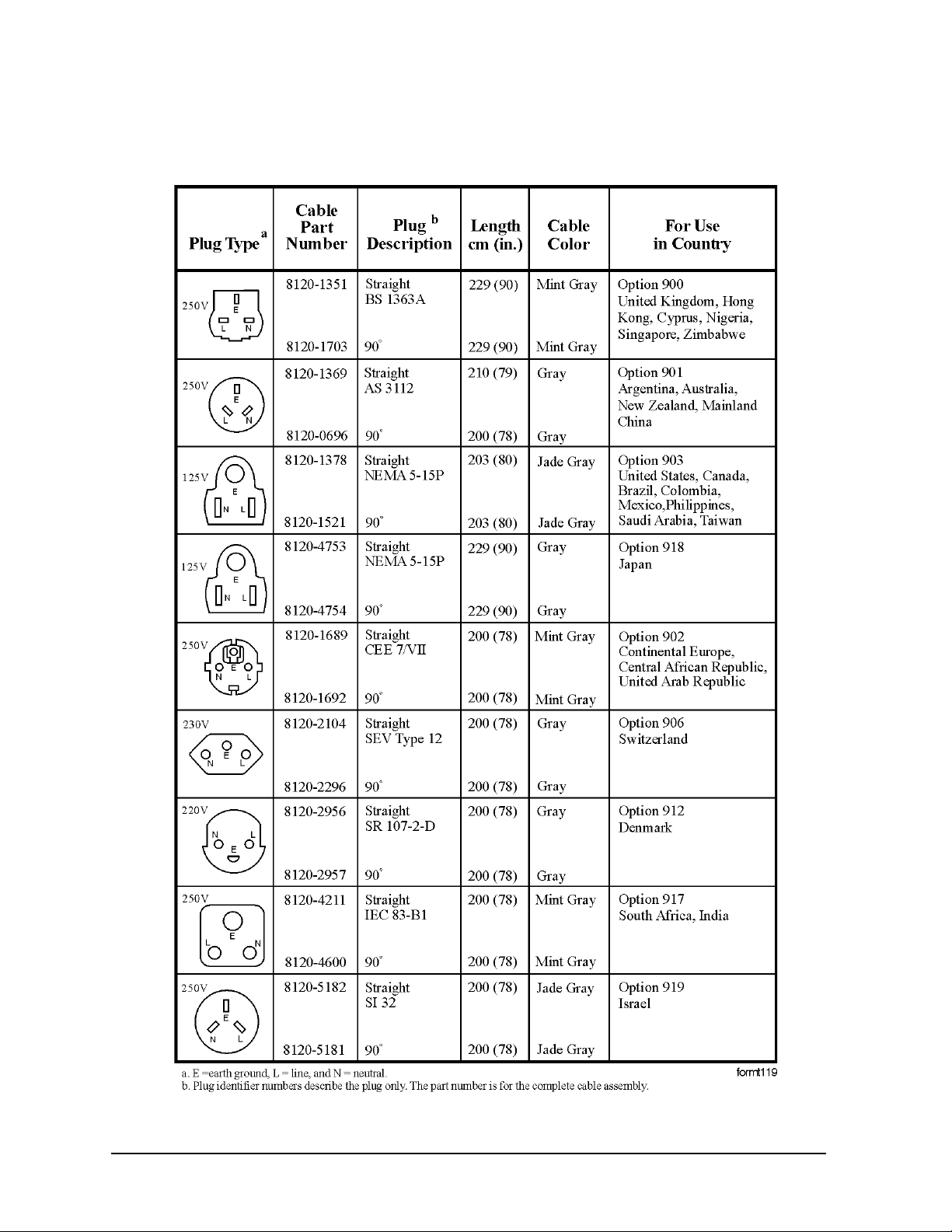
Various AC power cables are available that are unique to specific geographic areas. You can order
additional AC power cables for use in different areas. AC Power Cords, on page 12 lists the available
AC power cables, illustrates the pl ug conf igurations, and identifie s the geogr aphi c ar ea in which each
cable is appropriate.
NOTE The front panel switch is a standby switch only; it is not a LINE switch (power
disconnecting device).
WARNING Install the product so that the detachable power cord is readily identifiable
and easily reached by the operator. The detachable power cord is the
instrument disconnecting device. It disconnects the mains circuits from the
mains supply before other parts of the instrument. The front panel switch is
only a standby switch and is not a LINE switch. Alternatively, an externally
installed switch or circuit breaker (which is readily identifiable and is easily
reached by the operator) may be used as a disconnecting device.
CAUTION Always use the three-prong AC power cord supplied with this product. Failure to
ensure adequate earth grounding by not using this cord can cause product damage.
CAUTION This instrument has auto-ranging line voltage input, be sure the supply voltage is
within the specified range and voltage fluctuations do not to exceed 10 percent of
the nominal supply voltage.
Chapter 1 11
Page 12
Installation and Setup
Power Requirements
Table 1-3 AC Power Cords
12 Chapter 1
Page 13
Installation and Setup
Power Requirements
Battery Information
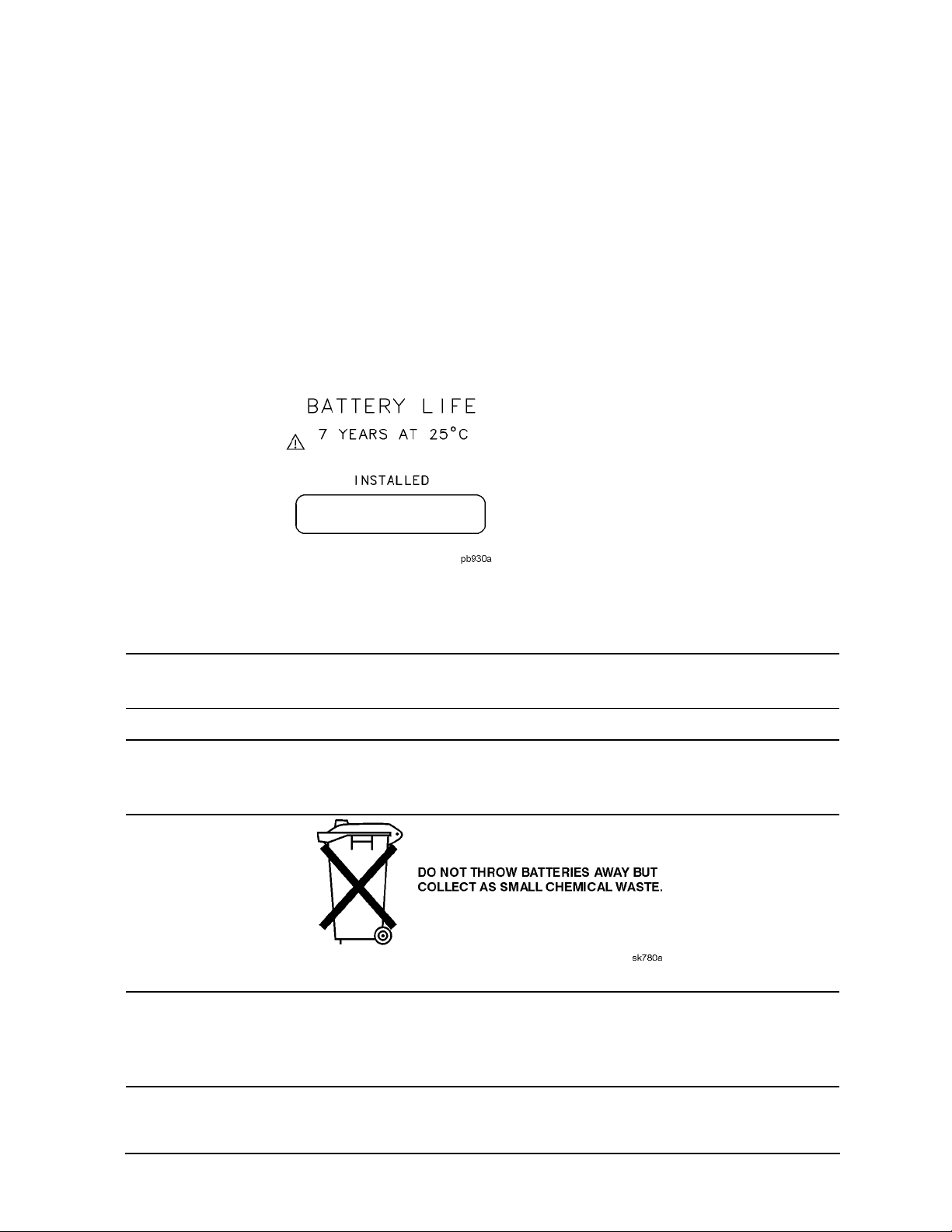
The analyzer uses a lithium battery to enable the internal memory to retain data. The date when the
battery was installed is on a label on the rear panel of the analyzer. See Figure 1-1
The minimum life expectancy of the battery is 7 years at 25 C , or 1 year at 55 C . If you experience
problems with the battery or the recommended time period for battery replacement has elapsed, see
“Returning an Analyzer for Service” on page 92.
If you wish to replace the battery yourself, you can purchase the service documentation that provides
all necessary test and maintenance information.
After replacing the analyzer battery, write the date of battery replacement on the rear-panel label.
Figure 1-1 Rear-Panel Battery Information Label
You can order the service documentation for Agilent spectrum analyzers through your Agilent Sales
and Service office. The documentation is described under “Options and Accessories” on page 65.
NOTE If the analyzer’ s clock d oes not wor k, the prob lem is the battery. See “Returning an
Analyzer for Service” on page 92.
WARNING Danger of explosion if battery is incorrectly replaced. Replace only with the
same or equivalent type recommended. Discard used batteries according to
the manufacturer’s instructions.
WARNING The Agilent Technologies E4402B, E4403B, E4404B, E4405B, E4407B,
E4408B, E4411B, E7402A, E7405A may be used with an E1779B
Rechargeable Battery Pa ck wh ich co ntains a Ni- Cd batt ery. The battery must
be recycled or disposed of properly.
Chapter 1 13
Page 14

Installation and Setup
Turning on the Analyzer for the First Time
Turning on the Analyzer for the First Time
❏ Plug in th e power cord.
WARNING If this product is to be energized via an external auto transformer for voltage
reduction, make sure that its common terminal is connected to a neutral
(earthed pole) of the power supply.
CAUTION The analyzer is shipped with a a transportation disk inserted in the disk drive to
prevent damage to the di sk dri ve dur ing t ranspo rtat ion. This trans portat ion di sk, or
a blank floppy disk, should be inse rt ed i n the disk drive whenever transporting the
analyzer.
NOTE Do not connect anything else to the analyzer yet.
❏ Choose a power on pr eference usin g the s witch on the rea r panel (refer to “Rear-Panel Features” on
page 31, item 14). The
PWR ALWAYS ON setting turns the analyzer on whenever external power
is applied. This mode is useful if an external power switch is used to control a rack of several
instruments. Neverthel ess, if you set the anal yzer to standby us ing the front pa nel
Standby key and
the external power is r emoved an d rest ored wi thin 20 second s, the a nalyze r will remai n in st andby.
PWR NORM setting assigns analyzer on/off control to the front-panel On and Standby keys
The
(see “Front-Panel Connectors and Keys” on page 24, item 23). If the analyzer is on and the
external power is removed and restored within 20 seconds, the analyzer will turn on. On the other
hand, if the external power is removed and restored after 20 seconds, the analyzer will remain in
standby regardless of the front-panel switch settings.
❏ Press the (On) key to turn the analyzer on.
Information Screen: An information screen appears during the initialization process. The information
screen contains the analyze r produc t number and a URL for accessi ng produc t suppor t in formati on on
the World Wide Web. See “Additional Information” on page 2.
NOTE The information screen displays for approximately 10 seconds before the
initializat i on process is complete.
Record the firmware revision and serial number, and keep it for reference. If you
should ever need to call Agilent Technologies for service or with any questions
regarding your analyzer, it will be helpful to have this information readily
available. You can also obtain the f irmware re visio n and se rial number b y pr essin g
System, More, Show System.
❏ Allow the analyzer to wa rm-u p for 5 minute s befo re making a cali brate d measur ement. To meet its
specifications, the analyz er mu st meet operat in g temperat ure conditions.
14 Chapter 1
Page 15

Installation and Setup
Turning on the Analyzer for the First Time
If the analyzer is an Agilent Technologies E4402B, E4403B, E4404B, E4405B, E4407B, or
E4408B, connect a BNC cable from the AMPTD REF OUT to INPUT 50 using an adapter.
After a 5 minute warm-up, press
System, Alignments, Align Now, All.
CAUTION When operating in dc coupled mode on analyzers with Option UKB ensure
protection of the input mixer by limiting the input level to 0 Vdc, +30 dBm.
When operating in ac coupled mode, ensure protection of the input mixer by
limiting the input level to 50 Vdc, +30 dBm.
NOTE It is normal to hear clicking when the Auto Alignment function is on. See
“Running Internal Alignments” on page 17 for more information.
Why Aren’t All the Personality Options Loaded in Memory?
Many measurement personality options are available for use with this instrument. If the option is
loaded in the instrument, you must also have a license key entered, to use it.
Some versions of instrument hardware my not have enough memory to accommodate all the options
that you have ordered. If this is the case you will need to swap the applications in/out of memory, as
needed. It may also be possible to upgrade your hardware to have more memory. Contact your local
sales/service office.
Using an External Reference
If you wish to us e an ext ernal 1 0 MHz sour ce as t he refe rence frequenc y, connect an external refere nce
source to the
dBm.
NOTE It is not necessary to connect the 10 MHz REF OUT to t he 10 MHz REF I N on the
1. T o use an ext ernal freque ncy ref erence , con nect it to the EXT REF IN connector on the rear panel
(see “Rear-Panel Features” on page 31).
10 MHz REF IN connector on the rear panel. The signa l le vel shou ld be grea ter tha n –15
rear of the analyzer. Doing so results in a “Frequency Reference Error” message.
Chapter 1 15
Page 16

Installation and Setup
Firmware Revision
Firmware Revision
To view the firmware revision of your analyzer, press System, More, Show System. If you call
Agilent Technologies regarding your anal yzer, it is helpful to have this revisi on and t he anal yzer seri al
number available.
TIP You can get automatic electronic notification of new firmware releases and other
product updates/information by subscribing to the Agilent Technologies Test &
Measurement E-Mail Notification Service for the PSA and ESA Series at
http://www.agilent.com/find/notifyme
16 Chapter 1
Page 17

Installation and Setup
Running Internal Alignments
Running Intern al Ali g nments
Each time the analyzer is powered on, the internal alignment routine runs automatically.
The analyzer was shipped from the factory with the Alignments mode set to
Align All.
Auto,
NOTE When the Alignment routine runs, you will hear the attenuator settings changing,
which generates noise. This is not an indication of trouble.
Manually Performing an Alignment
If the analyzer is an Agilent Technologies E4402B, E4403B, E4404B, E4405B, E4407B, or E4408B,
connect a BNC cable from the AMPTD REF OUT to INPUT 50 using an adapter. After a 5 minute
warm-up, press
System, Alignments, Align Now, All.
NOTE It is normal to hear clicking when the Auto Alignment function is on. During the
interval between sweeps, portions of the analyzer’s circuitry are realigned. Some
of the circuitry is controlled by relays. It is the rapid switching of these relays
between sweeps which causes the clicking sound. Under normal operation, these
relays will last over 50 years.
To eliminate the clicking sound, turn off the automatic alignment. (See the
Alignments key description in your User’s guide.”) With
Auto Align turned off,
however, the Align Now All function should be performed periodically. For more
information on how often to perform Align Now All when the Auto Alignment
function is of f, refer to the appropriate “S pecifications and Characteri stics” chapt er
in your specifications guide.
If
Auto Align, Off is selected, refer to the Specifications guide for t he co ndi tions required to main tai n
calibration.
Chapter 1 17
Page 18

Installation and Setup
Printer Setup and Operation
Printer Setup and Operation
A printer can be connecte d to your analyzer if it is eq uipped with an external I/O i nte rface. Supported
printers accept Hewlett-Packard Printer Control Language Level 3 (PCL3) or 5 (PCL5). Refer to the
documentation or specifications supplied with your printer, or contact the manufacturer to identify
your printer’s language.
Equipment
• IEEE 1284 compliant printer cable.
• Supported and tested printers are listed below. Note that there are many PCL3/5 printers that may
work with your analyzer, however, they have not been tested.
— PCL3 printers include most HP DeskJet printers.
— PCL5 printers include most HP LaserJet printers.
NOTE The following printers are not compatible with your analyzer:
HP Deskjet 720C, 722C, 820C and 1600C
Epson MX-80, FX-85, Stylus, and LQ-570
Printer Models Language Type Color Capable
HP DeskJet 310, 320, 350C, 400L PCL3 yes
HP DeskJet 500C, 550C, 600, 660C, 672C, 680C,
682C, 690C, 693C
HP DeskJet 840C, 850 C, 870C, 890C, 895C PCL3 yes
HP DeskJet 935C, 970C, 990C PCL3 yes
HP DeskJet 1120C, 1150C PCL3 yes
HP Inkjet 2000C PCL 3 yes
HP LaserJet III PCL3/5 no
HP LaserJet 4P PCL3/5 no
HP LaserJet 5L, 5M, 5N, 5P, 5SI PCL3/5 no
HP LaserJet 6L, 6MP PCL5 no
HP LaserJet 2100 Series, PCL3/5 no
HP LaserJet 4050N PCL3/5 yes
HP LaserJet 5000GN PCL3/5 yes
HP Professional Series 2500CM PCL3 yes
PCL3 yes
HP Professional Series 2500CM PCL3 yes
18 Chapter 1
Page 19

Installation and Setup
Printer Setup and Operation
Interconnection and Setup
1. Turn off the printer and the analyzer.
2. Connect the printer to the analyzer parallel I/O interface connector using an IEEE 1284 compliant
parallel printer cable.
3. If appropriate, configure your printer using configuration menus or switches. Refer to your
printer’s documentation for more specific information on configuring your printer.
4. Turn on the analyzer and printer.
5. Press
Print Setup on the front panel and then press the Printer Type menu key. Printer Type
accesses the following keys:
None None disables the an alyzer from attempting to print to a printer. This is the
appropriate setting if no printer is connected to the analyzer.
Custom Custom allows you to access the Define Custom menu keys. The Define
Custom
menu keys allow you to specify printer characteristics such as PCL
Level and printer color capability.
Auto Auto enables the analyzer to automatically attempt to identify the connected
printer when the
6. Press
Printer Type to access the Printer Type menu keys. Press Auto to make the analyzer attemp t
to identify the connected printer. When you press
Print key is pressed or when Printer Type is set to Auto.
Auto, the analyzer will respond in one of the
three following ways:
•The
Print Setup menu will be displayed with the Auto key selected and no new message will
be displayed in the display status line. This indicates that the analyzer has successfully
identified the connected printer and no further setup is required. As long as
selected in the
front panel
More 1 of 3, Show System.
•The
Print Setup menu will be displayed with the Custom key selected and one of the
Printer Type menu, the analyzer w ill attempt to identify the printer when the
Print key is pressed. The selected printer will be displayed by pressing System,
Auto remains
following diagnostic messages will be displayed in the display status line:
Unknown printer, Define Custom to set up printer
No printer response, Define Custom to set up printer
Invalid printer response, Define Custom to set up printer
This indicates that the analyzer was unable to automatically identify the connected printer, and
Custom has been selected in the Printer Type menu. Press Print Setup, Define Custom to
select specific printer characteristics such as the printer language (PCL3 or PCL5) and color
printing capability. Once you have set these characteristics to match those of your connected
printer, the printer setup process is complete. As long as
Printer Type menu, the analyzer will not attempt to automatically identify the connected
printer when the front panel
•The
Print Setup menu will be displayed with the None key se lected a nd the fo llowing mes sage
Print key is pressed.
Custom remains selected in the
will appear in the display status line:
Chapter 1 19
Page 20

Installation and Setup
Printer Setup and Operation
Unsupported printer, Printer Type set to None
This indicates that the anal yzer ha s su ccessf ully identi fied t he c onnect ed print er, but the printer
is not supported by the analyzer. As long as
analyzer will respond to any print command by displaying the message Printer Type is
None in the display status line.
None is selected in the Printer Type menu, the
7. Select the desired paper size by pressing
Print Setup, More, Page Size, then choose the
appropriate page size for which your printer is configured. This setting wil l remain uncha nged with
Preset or Power Cycle.
The factory default page size is
Restore Sys Defaults is executed.
Letter. The page size will be reset to Letter if System, More,
Testing Printer Operation
When you have completed the analyzer’s printer setup, press
Print Setup, then press Print on the
front panel. If the printer is ready and the printer setup was successful, a printout of the analyzer
display will be printed. If the pri nte r is not re ady, the message Printer Timeout will appear on the
analyzer display. Printer Timeout will remain on the display unt il the printe r is rea dy or unti l you
press
ESC to cancel the printout request.
NOTE There may be some small discrepancies in the color mapping of the analyzer
display to your color printer. Due to differences in display and printer
technologies, the default display colors do not map exactly to the printer colors.
For example trace 1 is yellow on your analyzer display while it maps to green on
your printer.
20 Chapter 1
Page 21

Installation and Setup
Protecting Against Electrostatic Discharge
Protecti ng Against Electrostatic Discharge
Electrostatic discha r ge ( ESD) can damage or destr oy elec troni c component s (the po ssibi lity of unseen
damage caused by ESD is present whenever components are transported, stored, or used).
Test Equipment and ESD
To help reduce ESD damage that can occur while using test equipment:
• Before connecting any coaxial cable to an analyzer connector for the first time each day,
momentarily short the center and outer conductors of the cable together.
• Personnel should be g rou nded with a 1 M resis tor-isolated wrist-strap before touching the center
pin of any connector and before removing any assembly from the analyzer.
• Be sure that all instruments are properly earth-grounded to prevent build-up of static charge.
WARNING Do not use these first three techniques when working on circuitry with a
voltage potential greater than 500 volts.
• Perform work on all components or assemblies at a static-safe workstation.
• Keep static-generating materials at least one meter away from all components.
• Store or transport components in static-shielding containers.
• Always handle printed circuit board assemblies by the edges. This reduces the possibility of ESD
damage to components and prevent contamination of exposed plating.
For information on ordering static-safe accessories, see “Accessories” on page 83.
Additional Information about ESD
For more information about ESD and how to preve nt ESD damage, contact t he Electrostati c Discharge
Association (http:// www .esda .org). The ESD st andards devel oped by this agenc y are sanction ed by the
American National Standards Institute (ANSI).
Chapter 1 21
Page 22

Installation and Setup
Safety Information
Safety Information
WARNING This is a Safety Class 1 Product (provided with a protective earth ground
incorporated in the power cord). The mains plug shall only be inserted in a
socket outlet pr ovided with a prot ective ea rth contact . Any inte rruption of t he
protective conductor inside or outside of the product is likely to make the
product dangerous. Intentional interruption is prohibited.
If this product is not used as specified, the protection provided by the
equipment could be impaired. This product must be used in a normal
condition (in which all means for protection are intact) only.
22 Chapter 1
Page 23

2 Front and Rear Panel Features
This chapter gives you an overview of the front and rear panels of your analyzer.
For details on analyzer keys and remote programming, refer to the User’s and
Programmer’s Guide. For connector specifications (including input/output le vel s) ,
see the Specifications guide.
23
Page 24
Front and Rear Panel Features
Front Panel Overview
Front Panel Overview
This section provides information on the analyzer’s front panel, including:
• Front Panel Connectors and Keys, see below
• “Display Annotations” on page 28
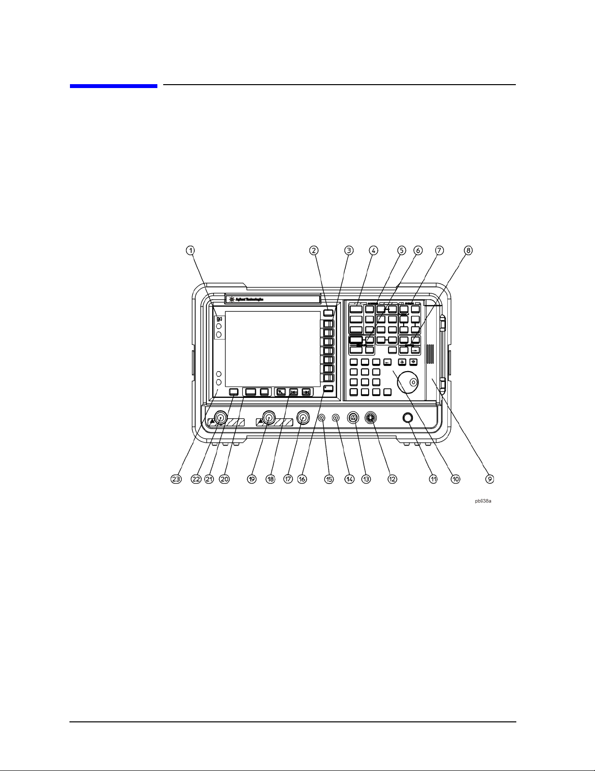
Front-Panel Connectors and Keys
1 Viewing Angle keys adjust the display so that it can be optimally viewed from
different angles.
2 Esc. The Esc (escape) key cancels any entry in progress. Esc will abort a print (if
one is in progress) and cl ear er ror mess ages f rom the st atus l ine at the bot to m of the
display. It also clears input and tracking generator overload conditions.
3 Menu keys are the unlabeled keys next to the screen. The menu key labels are the
annotation on the scr een nex t to t he unla beled k eys. Mo st of t he lab eled ke ys o n the
analyzer front panel (also called front-panel keys) access menus of keys having
related functions.
4 FREQUENCY Channel, SPAN X Scale, and AMPLITUDE Y Scale are the three
large keys that activate the primary analyzer functions and access menus of related
functions. The secondary labels on these keys (Channel, X Scale, and Y Scale) are
24 Chapter 2
Page 25

Front and Rear Panel Features
Front Panel Overview
used in some measurements.
5 CONTROL functions access menus that adjust the resolution bandwidth, adjust the
sweep time, and control the analyzer display. They also set other analyzer
parameters needed for making measurements.
6 MEASURE accesses a menu of keys that automate some common analyzer
measurements. Once a measurement is running,
menu keys for defining your measurement.
Meas Setup accesses additional
Meas Control and Restart access
additional measurement control functions.
7 SYSTEM functions affect the state of the entire analyzer.
Various setup and alignment routines are accessed with the
The green
The
Preset key resets the analyzer to a known state.
File key menu saves/loads setups, traces, states, limit-line tables, screens,
System key.
measurement results, and amplitude correction factors to or from analyzer
memory or the floppy disk dri ve. Th e
Now
function defined under File in your User’s guide.
Print Setup menu keys configure hardcopy outputs. The Print key
The
Save key immediately exec ut es t he Save
immediately sends hardcopy data to the printer. See your User’s guide for more
details.
8 MARKER functions control t he ma rkers , read out frequ encies and ampl itude s alon g
the analyzer trace, automat icall y locat e th e signal s of highe st ampli tude, and access
functions like
9 The Media Door on the right side of the front panel ac cesses the 3.5 inch dis k drive
Marker Noise and Band Power.
and the Earphone connector. The earphone connector provides a connection for an
earphone jack which bypasses the internal speaker.
10 The Data Control Keys, which include the step keys, knob, and numeric keypad,
change the numeric value of an active function such as center frequency, start
frequency, resolution bandwidth, and marker position.
The data controls will change the active function in a manner prescribed by that
function. For example, y ou can change center f requency i n fine steps with th e knob,
in discrete steps with the step keys, or to an exact (1 Hz resolution) value with the
numeric keypad.
The Knob provides fine incremental changes of functions such as center
frequency, reference level, and marker position. Clockwise rotation of the knob
increases values. The extent of alteration is determined by the size of the
measurement range. The speed at which the knob is turned affects the rate at
which the values are changed.
For slow sweeps, the analyzer uses a smooth panning feature which is designed
to move the trace di splay to the la test fun ction val ue as the knob is t urned. When
center , s top or, s ta rt f re que ncy or reference level i s adj usted, the signal will shift
right or left or up or down with the rotation of the knob before a new sweep is
actually taken. An asterisk is placed in the message block (the upper right-hand
corner of the analyzer display) to indicate that the data on the screen does not
reflect da ta at the current setting.
Chapter 2 25
Page 26

Front and Rear Panel Features
Front Panel Overview
The Numeric Keypad allows entry of exact values for many of the analyzer
functions. You may include a decimal point in the number portion. If not, the
decimal point is placed at the end of the number.
Numeric entries must be terminated with a units key. When a numeric entry is
begun, the menu keys show the units key labels. The units keys change
depending on what the active function is. For example, the units keys for
frequency span are
level are
+dBm, dBm, mV, V, and A.
GHz, MHz, kHz, and Hz, whereas the units for reference
NOTE If an entry from the numeric keypad does not coincide with an allowed function
value (for example, that of a 12 MHz bandwidth), the analyzer defaults to the
nearest allowable value.
The Step Keys () increase or decrease the active function value. The step
size depends upon the current analyzer measurement. Each press results in a
single step change. For those parameters with fixed values (resolution
bandwidth), the next value in a sequence is selected each time a step key is
pressed. Step size i s predict able (e.g ., 10% of span for center freq uency) and c an
be set for some functions (i.e., center frequency). Out-of-range values or
out-of-sequence values will not occur using these keys.
11 VOLUME. The VOLUME knob adjusts the volume of the internal speaker. The
speaker is turned on and of f with the
12 EXT KEYBOARD. The EXT KEYBOARD connector is a 6-pin mini-DIN connec tor.
Speaker On Off key in the Det/Demod menu.
The keyboard can be used to enter screen titles and filenames.
NOTE To avoid damage to the analyzer, always turn off power before plugging a
keyboard into the analyzer.
13 PROBE POWER provides power for high-impedance ac probes or other
accessories. (+15 V, 12.6 V, 150 mA maximum)
14 LO OUTPUT provides the proper lo cal oscilla tor signa l for use wi th extern al mixers
(Option AYZ).
15 IF INPUT connects to the IF OUTPUT of the external mixer (Option AYZ).
16 Return. The Return key accesses the previously selected menu. Continuing to
press
Return accesses earlier menus. Ret urn als o term inate s entr y of alpha numeric
functions (e.g., Title).
17 AMPTD REF OUT provides an amplitude reference signal of 50 MHz at –20 dBm.
Agilent ESA models E4402B, E4403B, E4404B, E4405B, E4407B, and E4408B
only.
18 Tab Keys are used to move around in the Limit editor, the Correction editor and
similar table-driven forms.
19 INPUT 50 (INPUT 75 for Option 1DP) is the signal input for the analyzer.
26 Chapter 2
Page 27

Front and Rear Panel Features
Front Panel Overview
CAUTION When operating in dc coupled mode on analyzers with Option UKB, ensure
protection of the input mixer by limiting the input level to 0 Vdc, +30 dBm.
When operating in ac coupled mode, ensure protection of the input mixer by
limiting the input level to 50 Vdc, +30 dBm.
20 The Next Window key can be used to select the active window in functions which
support split-screen display modes, such as Zone markers. (Refer to “Zone” in the
User’s guide for more information.) In such modes, pressing
Zoom switches
between the split-screen and full-sized display of the active window.
21 Help. Press the Help key and then any front panel or menu key to get a short
description of the key function and the associated SCPI command. The next key
you press will remove the help window from the display.
22 RF OUT 50 for Option 1DN or RF OUT 75 (for Option 1DQ) is the source
output for the built-in tracking generator. Option 1DN or 1DQ only.
CAUTION If the tracking gen era tor output power is too high, it may damage the device under
test. Do not exceed the maximum power that the device under test can tolerate.
23 The (On) key turns the analyzer on, while the Standby key turns most of the
analyzer off. An analyzer alignment is performed (if
Auto Align is on) every time
the analyzer is turned on. After turning on the ana lyzer , allow 5 minu tes of warm-up
time to ensure the analyzer will meet all specifications.
NOTE The analyzer continues to draw power even if the line power switch is in standby.
The main power cord can be used as the system disconnecting device. It
disconnects the mains circuits from the mains supply. The front-panel switch is
only a standby switch and is not a LINE switch (disconnecting device).
Chapter 2 27
Page 28
Front and Rear Panel Features
Front Panel Overview
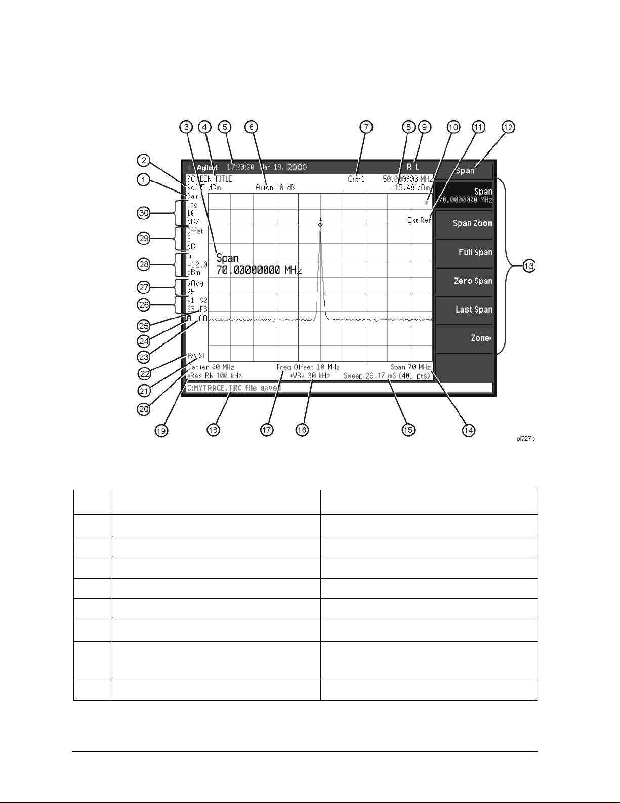
Display Annotations
Table 2-1 Screen Annotation
Item Description Associated Function Key
a
1
2 Reference level Ref Level
3 Active function block Refer to the description of the activated function.
4 Screen title
5 Time and date display Time/Date On Off
a,b
6
7 Marker frequency Marker or
8 Marker amplitude Marker
28 Chapter 2
Detector mode Detector
Change Title
RF attenuation Attenuation Auto Man
Marker Count On Off
Page 29

Front and Rear Panel Features
Table 2-1 Screen Annotation (Continued)
Item Description Associated Function Key
Front Panel Overview
9 GPIB annunciators
See programming documentation.
R - remote operation
L - GPIB listen
T - GPIB talk
S - GPIB SRQ
c
10
Data invalid indicator Sweep (Single) or View/Trace
11 Status Informational messages See your Instrument Messages and Functional
Tests manual for more information.
12 Key menu title Dependent on key selection.
13 Key menu See key label descriptions in the User’s guide for
more information.
14 Frequency span or stop frequency
Span or Stop Freq
15a Sweep time/Points Sweep Time Auto Man, Sweep Points
16a Video bandwidth Video BW Auto Man
17 Frequency offset Freq Offset
18 Display status line Displays analyzer status and error messages.
Cleared by pressing
Esc key. See your User’s
guide for more information.
19a Resolution bandwidth
Resolution BW Auto Man
20 Center frequency or start frequency Center Freq or Start Freq
21 Signal track Frequency, Signal Track
22 Internal preamp Amplitude, Int Preamp
d
23
24 Amplitude corrections are on (This indicates that
Auto alignment routine is on Auto Align
Correction On Off
the overall correction state is On. There may be
any or none of the individual corrections On.)
25 Trigger/Sweep
Trig, Sweep
F - free-run trigger
L - line trigger
V - video trigger
E - external (front) trigger
T - TV trigger (Options BAA, B7B only)
B - RF burst trigger (Opt B7E only)
C - continuous sweep
S - single sweep
Chapter 2 29
Page 30

Front and Rear Panel Features
Front Panel Overview
Table 2-1 Screen Annotation (Continued)
Item Description Associated Function Key
26 Trace mode
Trace
W - clear write
M - maximum hold
m - minimum hold
V - view
S - store blank
1 - trace 1
2 - trace 2
3 - trace 3
27 Average Average On Off
VAvg indicates video average on. PAvg indicates
power average on.
28 Display line
Display Line On Off
29 Amplitude offset Ref Lvl Offst
30 Amplitude scale Scale Type Log Lin
a. A # in front of any display annotation indicates that the function is uncoupled. (Refer to your User’s guide)
b. When the analyzer is set to the external mixer state (Option AYZ), item 6 changes to display Ext Mix in
place of Atten XdB. In addition, if Mixer Bias is on, a +I or I is appended to Ext Mix.
c. When the (*) is displayed, it means that some or all trace data may not match the anno tation due to po ssible
changes in analyzer settings.
d. AA indicates that auto alignment of all analyzer parameters, except the tracking generator and FM
demodulation options, will occur. AB indicates that auto alignment of all analyzer functions except the RF
section (and tracking generator and FM demodulation options) will occur. No indicator will appear if auto
alignment is off.
30 Chapter 2
Page 31

Rear-Panel Features
Front and Rear Panel Features
Rear-Panel Features
1 Power input is the input for the ac line power source. Make sure that the
line-power source outlet has a protective ground contact.
2 DC Power i s the inpu t for the dc power sour ce. Refer to the “Powe r Require ments”
section in the specifications guide for your analyzer.
CAUTION AC line power and dc power should not be plugged in simultaneously.
3 Line Fuse. The fuse is removed by twisting counterclockwise 1/4 turn. Replace
only with a fuse of the same rating. See the label on the rear panel.
4 Service Connector. The service connector is for service use only.
5 Inputs/Outputs (Refer to the specifications guide for more information.)
5a VGA OUTPUT drives an external VGA compatib le mo nit or wit h
a signal that has 31.5 kHz horizontal, 60 Hz vertical
synchronizing rate, non-interlaced.
5b GATE/HI SWP OUT (TTL) is high when the ana lyzer is s weeping
or when
5c GATE TRIG/EXT TRIG IN (TTL) accepts the positive edge of an
Gate (Option 1D6) is active.
external voltage input that triggers the analyzer internal sweep
source or the gate function (Time Gate, Option 1D6).
Chapter 2 31
Page 32

Front and Rear Panel Features
Rear-Panel Features
Table 2-2 and Table 2-3. show the appropriate rear panel slots to be used for the optional cards
available with the Agilent ESA Spectrum Analyzers. Refer to Table 2-2. if you have an Agilent
ESA-L Series Spectrum Analyzer. Refer to Table 2-3. if you have an Agilent ESA-E Series Spectrum
Analyzer.
(P) = Preferred Card Slot
(A) = Acceptable Card Slot
(–) = Unacceptable Card S l ot
Table 2-2 Agilent ESA-L Series (E4403B, E4408B, E4411B)
Slot # 1256
GPIB and Parallel (Option A4H) P A – –
Serial and Parallel Interface (Option 1AX) P A – –
IF, Video, and Sweep Ports (Option A4J) – – P –
Frequency Extension
a
––P
a. The Frequency Extension Assembly comes standard with the Agilent E4408B.
Table 2-3 Agilent ESA-E Series (E4401B, E4402B, E4404B, E4405B, E4407B)
Slot #
GPIB and Parallel Interface (Option A4H)
b
RS-232 and Parallel Interface (Option 1AX)b P A A A – –
Fast Time Domain Sweeps (Option AYX)
c
IF, Video, and Sweep Ports (Option A4J)c A A A A P A
FM Demodulation (Option BAA)
d
Noise Figure (Option 21 9) A A P A – –
Frequency Extension
e
Digital Signal Procession and Fast ADC
(Option B7D)
RF Communications Hardware (Option B7E) – – – – P –
a
1
23456
PAAA– –
–APA––
– APAAA
– AAAAP
–––P––
ACPR Dynamic Range Extension (Option 120) – P AAAA
Bluetooth
f
FM Demodulation (Option 106)d
,g
– APAAA
a. S ome cards may not be installed due to mechanical interference.
b. Only one optional remote interface (Option A4H or Option 1AX) can be installed at a time.
c. Only one IF and Sweep Port option (Option A4J or Option AYX) can be installed at a time.
d. Only one demod option (Option BAA or Option 106) can be installed at a time.
32 Chapter 2
Page 33

Front and Rear Panel Features
Rear-Panel Features
e. The Frequency Extension Assembly comes standard with the Agilent E4404B, E4405B and
E4407B.
f. Bluetooth
license.
g. Option 106 is required to make measurements in Bluetooth™ Measurement Personality
(Option 228)
6 GPIB and parallel interface (Option A4H) is an optional interface. GPIB supports
is a trademark owned by its proprietor and used by Agilent Technologies under
remote analyzer operation. A parallel port is included for printing only.
7 RS-232 and parallel interface (Option 1AX) is an optional interface. RS-232
supports remote analyzer operation. A parallel port is included for printing only.
NOTE Printing is only supported from the parallel port.
8 IF, Video, and Sweep Ports (Option A4J or Option AYX): (Refer to the
specifications guide for more information.)
SWP OUT provides a voltage ramp corresponding to the sweep of the analyzer
(0 V to 10 V).
HI SWP IN (TTL) can be grounded to stop and reset the sweep. Once the sweep
has been stopped, removing the ground will trigger the start of a new sweep.
HI SWP OUT (TTL) is high when the analyzer is sweeping.
AUX VIDEO OUT provides detected video output (before the analog-to-digital
conversion) proporti onal to vertic al deflecti on of the trace. Outp ut is from 0 V to
1 V. Amplitude-correction factors are not applied to this signal.
NOTE The video output signal may be blanked during retrace when automatic alignment
is on. This eff ect c an b e redu ced wit h longe r sweep times , or elimi nated by tur ning
Auto Align off. For more information, refer to the Alignments key description in
the ESA User’s and Programmers Reference, Volume 1.
AUX IF O U T is a 50 , 21.4 MHz IF output that is t he down -conve rted s ignal o f
the RF input of the analy zer. Amplitude-correction factors a re not appl ied to thi s
signal. This output is taken after the resolution bandw idth filters and step gains
and before the log amplifier.
NOTE Only one IF and Sweep Port option (Option A4J or Option AYX) can be installed
at a time.
9 FM Demod (Option BAA) demodulates, displays, and measures deviation on FM
signals. You can listen to audio signals on a built-in speaker or with an earphone.
Refer to “Det/Demod” and “FM Demodulation (Option BAA)” in the Options
chapter for more informati on.
Bluetooth
deviation on Bluetooth
Chapter 2 33
FM Demodulation (Option 106) demodulates, displays and measures
signals. Refer to “Det/Demod” and “Bluetooth FM
Page 34

Front and Rear Panel Features
Rear-Panel Features
Demodulation (Option 106)” in the Options chapter for more information.
10 Frequency Extension Assembly controls the microwave front-end components in
the Agilent E4404B, E4405B, E4407B, and E4408B.
PRESEL TUNE OUTPUT provides a signal to contr ol extern al presel ecte d mixers if
External Mixing (Option AYZ) is installed.
11 Card Slot Identification Numbers. Refer to Table 2-2 and Table 2-3 for card slot
versus option card compatibility information.
12 10 MHz REF IN accepts an ex ternal frequ ency source to prov ide the 10 MHz, 15 to
+10 dBm as a timebase.
NOTE It is not necessary to connect the 10 MHz REF OUT to t he 10 MHz REF IN on the
rear panel of the analyzer. Doing so will result in a Frequency Reference Error
message.
13 10 MHz REF OUT provides a 10 MHz, 0 dBm minimum, t imebase refer ence signal.
14 Power On Selection selects an analyzer power preference.
PWR ALWAYS ON setting turns the analyzer on whenever external power
The
is applied. This mode is useful if an external power switch is used to control a
rack of several instruments. Nevertheless, if you set the analyzer to standby
using the front panel
Standby key (see Figure 2-1. on page 22, item 23) and the
external power is removed and restored within 20 seconds, the analyzer will
remain in standby.
Power Always On
Analyzer state before removing
power
On On On
Standby Standby On
PWR NORM setting assigns analyzer on/off control to the front-panel On
The
and
Standby keys (see Figure 2-1. on page 22, item 23). If the analyzer is on
A lapse in power
< 20 sec.
A lapse in power
> 20 sec.
and the external power is removed and restored within 20 seconds, the analyzer
will turn on. On the other hand, if the external power is removed and restored
after 20 seconds, the analyzer will remain in standby regardless of the front
panel switch settings.
Power Norm
Analyzer state before removing
power
On On Standby
Standby Standby Standby
34 Chapter 2
A lapse in power
< 20 sec.
A lapse in power
> 20 sec.
Page 35

Front and Rear Panel Features
Rear-Panel Features
15 DC Fuse protects the analyzer fr om drawing to o much dc po wer . Re place onl y with
a fuse of the same rating. See the label on the rear panel.
Chapter 2 35
Page 36

Front and Rear Panel Features
Key Overview
Key Overview
The keys labeled FREQUENCY Channel, System, and Marker are all examples of front-panel keys.
The front-panel keys are dar k gray, light gray, green, or whi te in col or. Front-panel keys that are white
perform an immediate action rather than bringing up a menu. The only green key is the
which performs an analyzer reset (A summary of all front panel keys and their related menu keys can
be found in user’s guide for your analyzer). Pressing most of the dark or light gray front-panel keys
accesses menus of functions that are displayed along the right side of the display. These are called
menu keys.
Menu keys list functions ot her than tho se accesse d directl y by the front pa nel keys. To activate a menu
key function, press the key immediately to the right of the annotation on the screen. The menu keys
that are displayed depend on which front-panel key is pressed and which menu level is enabled.
If a menu key funct ion’s value can be changed, it i s cal led an ac tive functi on. The fu nctio n labe l of the
active function is highlighted after that key has been selected. For example, press
. This calls up t he menu of re lated ampl itude funct ions. Note t he fun ction label ed Ref Level (the
Scale
default selected key in the Amplitude menu) is highlighted.
Ref Level also appears in the active
function block, i ndicat ing t hat i t i s the acti ve ampl itude funct ion a nd can now be ch anged u sing any of
the data entry controls.
Preset key,
AMPLITUDE Y
A menu key with On and Off in its label can be use d to turn t he menu key’s function on or off. To turn
the function on, press the menu key so that On is underlined. To turn the function off, press the menu
key so that Off is underlined. In the manual, when On should be underlined, it will be indicated as
Function (On).
A function with Auto and Man in the label can either be auto-coupled or have its value manually
changed. The value of the function can be changed manually using the numeric keypad, knob, or step
keys. To auto-couple a function, press the menu key so that Auto is underlined. In the manual, when
Auto should be underlined, it will be indicated as Function (Auto).
In some key menus, one key label will always be highlighted to show which key has been selected.
For example, when you press
Marker, you will access a menu of keys in which some of the keys are
grouped together by a blue bar (on analyzers with a color display) on the left side of the menu. The
Normal key, which is the Marker menu default key, will be highlighted. When you press another key
within the blue bar region, such as
Delta, the highlight will move to that key to show it has been
selected.
36 Chapter 2
Page 37

Front and Rear Panel Features
Key Overview
In other key menus, one key label will always be highli ghted to show which key ha s bee n selec ted but
the menu is immediately exited when a selection is made. For example, when you press the
Orientation key (on the Print Setup menu), it will bring up its own menu of keys. The Portrait key,
which is the Orientation menu default key, will be highlighted. When you press the
Landscape key,
the highlight will move to that key to show it has been selected and the screen will return to the
Print Setup menu.
The arrow keys locat ed be low the analyzer dis play (sometimes refer re d t o as Tab keys) ca n b e used to
navigate within tables, for example the Limit-Line table. These keys are used to move between rows.
The Left-arrow key moves up, while the right-arrow key moves down. While navigating through the
table, the cursor (inverse video highlight) stays in the same column. Navigating left or right in the
table is accomplished by choosing the desired field using the front-panel keys.
Chapter 2 37
Page 38

Front and Rear Panel Features
Front and Rear Panel Symbols
Front and Rear Panel Symbols
This symbol is used to indicate power ON (green LED).
This symbol is used to indicate power STANDBY mode (yellow LED).
This symbol indicates the input power required is AC.
The instruction documentation symbol. The product is marked with this symbol
when it is necessary for the user to refer to instructions in the documentation.
The CE mark is a registered trademark of the European Community.
The C-Tick mark is a r egistered t rademark o f the Austral ian Spectrum M anagement
Agency.
This ISM device complies with Canadian ICES-001.
Cet appareil ISM est conforme a la norme NMB du Canada.
This is also a symbol of an Industrial Scientific and Medical Group 1 Class A
product (CISPR 11, Clause 4).
The CSA mark is a registered trademark of the CSA International.
This symbol indicates separate collection for electrical and electronic equipment
mandated under EU law as of August 13, 2005. All electric and electronic
equipment are required to be separated from normal waste for disposal (Reference
WEEE Directive 2002/96/EC).
Indicates the time period during which no hazardous or toxic substance elements
are expected to leak or deteriorate during normal use. Forty years is the expected
useful life of the product.
This symbol on all pri mary and secondar y packagin g indicat es comp liance t o China
standard GB 18455-2001.
This equipment is Class A suitable for professional use and is for use in
electromagnetic environments outside of the home.
38 Chapter 2
Page 39

3 Making a Basic Measurement
This chapter provides information on basic analyzer operation. For more information on making
measurements, see the measurement guide for your analyzer.
39
Page 40

Making a Basic Measurement
This chapter is divided into the following sections:
•“Using the Front Panel” on page 41
•“Presetting the Spectrum Analyzer” on page 42
•“Viewing a Signal” on page 43
CAUTION Ensure that the t ot al power of all signals at the analyzer inp u t does not exceed +30
dBm (1 watt).
Basic Assumption
The material in this chapter is presented with the assumption that you understand the front and rear
panel layout, and display annotations of your analyzer. If you do not, refer to “Front and Rear Panel
Features” on page 23.
NOTE The display examples in this book are made using various analyzer models, you
may see some variations depending upon your analyzer.
40 Chapter 3
Page 41

Making a Basic Measurement
On Off
Signal Track
Catalog
dBm
Y Axis Units
13.2550000 GHz
CF Step
10.00 dB
Auto Man
Attenuation
Using the Front Panel
Using the Front Panel
Entering Data
When setting measurement parameters, there are several ways to enter or modify the value of the
active function:
Knob
Arrow Keys
Numeric Keypad
Unit Softkeys
Enter Key
Increments or decrements the current value.
Increments or decrements the current value.
Enters a specific value. Then press the desired terminator (either a unit
softkey, or the
Terminate a value that req uires a unit-of-measur e m e nt .
Terminates an entry when either no unit of measure is needed, or you want to
use the default unit.
Enter key).
Using Menu Keys
Menu Keys (which appear along the right side of the display) provide access to many analyzer
functions. Here are examples of menu key types:
Toggle Allows you to activate/deactivate states.
Example: Toggles the selection (underlined choice) each
time you press the key.
Submenu Displays a new menu of softkeys.
Example: A submenu key allows you to view a new menu of
softkeys rela ted to the submenu key category.
Choice Allows you to make a selection from a list of values.
Example: A choice key displays the currently selected
submenu choice, in this example, dBm. When the
choice is made, the submenu automatically
returns.
Adjust Highlights the softkey and sets the active function.
Examples: Press this type of key and enter a value.
The default for softkeys with an automatic (
or manual (
enter a value, the selection changes to manual.
You can also press the softkey twice to change to
manual.
Man) choice is automatic. After you
Auto)
Chapter 3 41
Page 42

Making a Basic Measurement
Presetting the Spectrum Analyzer
Presetting the Spectrum Analyzer
Preset provides a known starting point for making measurements. The analyzer has three types of
preset:
Factory Preset Restores the analyzer to its factory-defined state.
User Preset Restores the analyzer to a user-defined state.
Mode Preset This type of preset restores the currently selected mode to a known state.
For details, see the User’s/Programmer’s manual.
Preset Type is set to Factory, pressing the green Preset key triggers a factory preset. When
When
Preset Type is set to User, pressing Preset displays th e softkeys Factory Preset, User Preset, and
Mode Preset (if applicabl e) ; you then select the pre set you want. If Preset Type is set to Mode, but a
personality is not installed, pressing
Creating a User Preset
Preset triggers a factory preset.
If you constantly use settings which are not the factory defaults, use the following steps to create a
user-defined preset:
1. Set analyzer parameters as desired.
2. Press
System, Power On/Preset, Save User Preset to set the current parameters as the user
preset state.
3. Press
Preset to select User in the same softkey menu to enable user preset as an option.
Disabling User Preset
Go to the Power On/Preset menu (press
Factory or Mode.
System, Power On/Preset) and select a Preset Type of
42 Chapter 3
Page 43

Making a Basic Measurement
10 MHz
Viewing a Signal
Viewing a Signal
1. Press Preset. If the softkeys Factory Preset and User Preset appear, select Factory Preset.
2. Connect the analyzer’s rear panel 10 MHz REF OUT to the front-panel input.
Setting Reference Level and Center Frequency
NOTE The display examples in this section are made using various analyzer models, you
may see some variations depending upon your analyzer.
3. Set the reference level to 10 dBm: Press
4. Set the center frequency to 30 MHz: Press
AMPLITUDE, 10, dBm.
FREQUENCY, Center Freq, 30, MHz.
The 10 MHz reference signal spectrum appears on the display, as shown in Figure 3-1.
NOTE The display examples in this book are made using various analyzer models, you
may see some variations depending upon your analyzer.
Figure 3-1 10 MHz Internal Reference Signal and Associated Spectrum
Chapter 3 43
Page 44

Making a Basic Measurement
10 MHz
Viewing a Signal
Setting Frequency Span
5. Set the frequency span to 50 MHz: Press
This displays the signal as shown in Figure 3-2.
Figure 3-2 Span Changed to 50 MHz
SPAN, 5, 0, MHz.
Reading Frequency & Amplitude
6. Place a marker (labeled 1) on the 10 MHz peak, as shown in Figure 3-3.
Peak Search.
Press
Note that the frequency and amplitude of the marker appear both in the active function block, and
in the upper-right corner of the scree n. You can use the knob, the arrow keys, or th e softk eys in the
Peak Search menu to move the marker. Pressing
7. If you have moved the marker, return it to the peak of the 10 MHz signal.
Esc removes the value from the display.
Changing Reference Level
8. Press
AMPLITUDE, and note that reference level (Ref Level) is now the active function. Press
Marker ➞Mkr ➞ Ref Lvl.
Note that changing the reference level changes the amplitude value of the top graticule line.
Figure 3-4 shows the relationship between center frequency and reference level. The box
represents the analyzer display. Changing the center frequency changes the horizontal placement
of the signal on the display. Changing the reference level changes the vertical placement of the
signal on the display. Increasing the span increases the frequency range that appears horizontally
across the display.
44 Chapter 3
Page 45

Figure 3-3 A Marker on the 10 MHz Peak
Marker Active function
Making a Basic Measurement
Viewing a Signal
Figure 3-4 Relationship Between Frequency and Amplitude
Chapter 3 45
Page 46

Making a Basic Measurement
Viewing a Signal
Improving Frequency Accuracy
9. While not all of the zeros following the decimal in the active function block are significant, the
numbers after the decimal in the marker annotation (upper-right corner of screen) are significant.
To improve the accuracy of the frequency reading in the marker annotation, turn on the frequency
count function by pressing
Freq Count.
10.Note softkey
Marker Count On Off. If Off is underlined, press the softkey to toggle marker count
on.
As shown in Figure 3-5:
• The marker annotation changes from Mkr1 to Cntr1.
• The displayed resolution in the marker annotation improves.
NOTE When you use the frequency count function, if the ratio of the resolution
bandwidth to the span is less than 0.002, the following message appears on the
display: Marker Count: Widen Res BW
This indicates that the resolution bandwidth is too narrow.
11.Press
Marker ➞, Mkr ➞ CF to move the 10 MHz peak to the center of the display.
Valid Marker Count Range
12.Move the marker down the skirt of the 10 MHz peak. Note that although the readout in the active
function changes, as long as the marker is at least 26 dB above the noise, the counted value
(upper-right cor ner of disp lay) do es no t change (see Figure 3-6). For an accurate co unt, the marke r
does not have to be at the exact peak.
NOTE Marker count functions properly only on CW signals or di scret e peaks. For a valid
reading, the marker must be 26 dB above the noise.
13.Press
BW/Avg, Res BW, then enter a new value. This action makes the resolution bandwidth the
active function and allows you to experiment with different resolution bandwidth (RBW) values.
14.Press
Marker, Off to turn the marker off.
NOTE After properly sett ing t he anal yzer to dis play yo ur s ignal , you ca n save t he set ting s
as either a user preset (press
System, Power On/Preset, Save User Preset), or a
file (see “Saving a File” on page 55).
46 Chapter 3
Page 47

Figure 3-5 Increasing Marker Frequency Accuracy
Frequency Count
increases accuracy
Making a Basic Measurement
Viewing a Signal
Figure 3-6 Using Marker Counter
Chapter 3 47
Page 48

Making a Basic Measurement
Viewing a Signal
48 Chapter 3
Page 49

4 Viewing Catalogs and Sa ving Files
49
Page 50

Viewing Catalogs and Saving Files
The analyzer stores and retriev es data simi larly to the way that a personal c omputer (PC) d oes: both ha ve
internal storage and a fl oppy disk drive. While a PC has an int er nal drive, the analyzer’s internal st ora ge
is nonvolatile (fl ash) memory, which acts as an internal drive. As with a PC, both t he internal storage a nd
the floppy disk drive have directory and sub-directory capability; in the analyzer, directories and
subdirectories are called catalogs.
This chapter tells you how to:
• locate catalogs and view files, on page 51.
• save a file, on page 55.
For more information on catalogs and files, see the Measurement guide.
50 Chapter 4
Page 51

Viewing Catalogs and Saving Files
File Menu Functions
File Menu Functions
This chapter describes how to use the functions located under the front-panel File key. Data storage and
retrieval are handle d si mi la rl y to t hat of personal computers (PCs). Li ke PCs, t hese analyzers include an
internal storage drive and a floppy disk drive, both of which have directory and sub-directory capability.
NOTE The descriptions in this section assume the analyzer has firmware revision A.04.00 or
later. The file menu functions in earlier firmware are different. If you would like to
upgrade your analyzer to the latest firmware revision, please visit the following web site:
http://www.agilent.com/find/esa
You will learn how to do all of the following:
• locate and view files in the catalog
• create a directory
• format a floppy disk
• save a file
•load a file
• rename a fi le
• copy a file
• delete a file
NOTE The display examples in this book are made using various analyzer models, you may see
some variations depending upon your analyzer.
Locating and viewing files in the catalog
Techniques for locating files and directories are consistent throughout the various file menu functions.
Although this section provides specific information about navigation in the catalog, you may wish to
refer back to this section when performing other operations of the file menu.
The analyzer has three default catalogs (directories):
• State, which stores analyzer settings.
• Trace, which stores trace information.
• Screen, which stores screen captures of the display in .gif or .wmf format.
NOTE Trace files are not bitmap files. Files saved as Trace cannot be imported into other
applications or converted. If you require the use of other applications, for example
Microsoft‚ Word or Microsoft‚ Excel, be sure to save your files as .gif or .wmf formats
using Screen for your file Type.
Chapter 4 51
Page 52

Viewing Catalogs and Saving Files
File Menu Functions
Press File, Catalog to bring up a screen display as shown in Figure 4-1.
Figure 4-1. Catalog Menu
NOTE Use the front-panel Step Keys or Knob and the Dir Up or Dir Select keys to move up
and down within the directory information box.
1. The entry fields show the parameters for the files viewed. Entry fields that are being modified or are
modifiable are indicat ed by hi ghl ighting (inverse video) . Each fi l e menu fun cti on has its own unique
set of entry fields pertaining to that function. Below are the fields listed under the catalog key:
a. Name: field states the filename.
b. Show Type: field displays the type of files viewed.
c. Path: field displays the drive and directory location of the files.
2. The directory information box displays the drives, directories, and/or files currently described in the
entry fields. Highlighting a row of information selects that location and updates the entry fields.
There are four column headings in this area of the display. They are described as follows:
a. Name: column states the drive ( [-A-] or [-C-]) if at t he t op l eve l on the drive, directory na me,
or filename.
52 Chapter 4
Page 53

Viewing Catalogs and Saving Files
File Menu Functions
b. Type: column displays the extension of the filename, for example, .SET, .STA, .TRC.
Directories are displayed as DIR and drives have nothing listed under Type:. They are only
designated by the Name: column ([-A-] or [-C-]).
c. Size: column displays the size of the file in bytes.
d. Modified: column displays the date and time the last change occurred.
3. The softkey menu has four options:
Type: allows you to choose the type of file you wish to view. (You may view all types by using
a.
the
All key under Type.)
b. Sort: Under the Sort key, you can sort by any of the four columns and you can choose up
(ascending) or down (descending).
Dir Up: moves you up one directory level. If you are already at the top level, this key moves you
c.
up to the drive level, displaying the available disk drives.
Dir Select: moves you down into the highlighted directory or up into the next level (directory or
d.
drive) if the “. .” under the Name: column is highlighted.
NOTE Navigation keys: Use the front-panel Step Keys or Knob and the Dir Up or Dir Select
keys to move around in the directory information box.
4. The drive space l ine shows t he number of bytes us ed on the drive and the nu mber of byt es stil l free o n
the drive.
Creating a directory
Directories and sub-directories can be created on both the A: floppy disc and the internal C: drive. This
allows maximum flexibili ty in organizing files. For this exa mple, we will create a directory on the C:
drive.
1. Press
2. Navigate through the file system until the Path: field displays C:\. (Use the Step Keys, Knob, Dir
3. Press
4. Press
5. To make a sub-directory, scroll down to the START directory you just created and press
File, More 1 of 2, Create Dir. Your screen should look similar to Figure 4-1, except the entry
fields will be Dir Name: and Path: and the Heading will read: Directories.
Up, and/or Dir Select keys.)
Name and enter the name, “START” using the Alpha Editor. (The numeric keypad is also
available for the filename.) Press
title. (Use the
Create Dir Now to execute the operation. The message: Creating Directory appears on
Bk Sp hardkey on the front panel to make corrections.)
Enter (hardkey) when the Dir Name: field contains this directory
the screen. Then the status bar displays: Directory C:\START created.
Dir Select.
The Path: field should now read: C:\START\. Repeat Steps 3 and 4 above, using a new name. The
status bar now should read: Directory C:\START\new name created.
Formatting a Floppy Disk
You can format a floppy disk in the analyzer. The format is MS-DOS‚1. Note that it is not necessary to
Chapter 4 53
Page 54

Viewing Catalogs and Saving Files
File Menu Functions
format your floppy disk with the analyzer; preformatted disks can be used with the analyzer.
1. Place the 1.44-MB dis k you wish to format in to the floppy drive ( A:\ ) of the analyzer. Only 1.44-MB
floppy disks are supported by the analyzer. Therefore, 720-kB floppy disks will not work reliably.
2. Access the
Format key by pressing File, More, and then Format. The directory information box is
active (highlighted), however, only the floppy disk volume [-A-] is shown on the display.
The directory information box displays all files present on the floppy disk inserted in drive “A:”. If
you have not inserted a disk into drive “A:”, or the disk you are attempting to format has no
pre-existing formatting, the error message: bad, missing, or unformatted disk is displayed
in the statu s line.
3. Press
Format Now. The following message appears in the display window: WARNING: You are
about to destroy ALL data on Volume A:. Press Format Now again to proceed
or any other key to abort. To abort disk format, press any key but
Format Now. When a
disk is formatted, all data on the disk is destroyed.
4. Press
Format Now a second time to format the disk. You will see the mes sage: Formatting Disk
in the display window. Pressing any other key after receiving the warning in step 3 on page 54, will
abort the formatting process. See Figure 4-2. The format process takes approximately three minutes.
Figure 4-2. Format Menu
5. When formatting is complete, a message, Volume A: formatted appears on the status line. The
disk is now ready to save files.
1. MS-DOS‚ is a U.S. registered trademark of Microsoft Corporation.
54 Chapter 4
Page 55

Viewing Catalogs and Saving Files
Saving a File
Saving a File
You can save files (setups, states, traces, li mits, corr ections, meas urement res ults, or screens ) to a floppy
disk (A:\), or the internal drive (C:\). In this example you will save a trace to the internal C: drive.
NOTE Trace files are not bitmap files. Files saved as Trace cannot be imported into other
applications or converted. If you require the use of other applications, for example
Microsoft‚ Word or Microsoft‚ Excel, be sure to save your files as .gif or .wmf formats
using Screen for your file Type.
Step 1. Set up the analyzer trace
1. Perform a factory preset by pressing Preset, Factory Preset (if present).
2. Turn on the internal 50 MHz alignment signal of the analyzer as follows:
•For the Agilent E4401B and E4411B, use the internal 50 MHz alignment signal of the analyzer a s
the signal being measured. Press
• For all other models connect a cable between the front-panel AMPTD REF OUT to the analyzer
INPUT, then press
Input/Output, Amptd Ref Out (On).
Input/Output, Amptd Ref (On).
3. Set the center frequency to 50 MHz by pressing press
4. Set the span to 75 MHz by pressing
SPAN, Span, 75, MHz. The reference signal will appear on the
display.
FREQUENCY, Center Freq, 50, MHz.
Chapter 4 55
Page 56

Viewing Catalogs and Saving Files
Saving a File
5. View trace 1 and put it into maximum hold by pressing View/Trace, Max Hold. (Trace 1 should
already by underlined, but if not, press
Trace 1 2 3 until 1 is underlined and then press Max Hold.)
Your analyzer display should look similar to Figure 4-3.
Figure 4-3. Viewing Trace 1
6. Activate trace 2 and pu t it into minimum hold by pr essing
should look similar to Figure 4-4.
Figure 4-4. Viewing Traces 1 and 2
Trace (2), Min Hold. Your analyzer display
56 Chapter 4
Page 57

Viewing Catalogs and Saving Files
Saving a File
7. Activate trace 3 by pressing Trace (3), Clear Write. Your analyzer display should look similar to
Figure 4-5.
Figure 4-5. Viewing Traces 1, 2, and 3
Step 2. Save the file
1. To access the Save menu, press, File, Save.
2. Select the type of file you want to save. In this example you are saving a trace; press
NOTE Trace files are not bitmap files. Files saved as Trace cannot be imported into other
applications or converted. If you require the use of other applications, for example
Microsoft‚ Word or Microsoft‚ Excel, be sure to save your files as .gif or .wmf formats
using Screen for your file Type.
3. Select the trace you wish to save (1, 2, 3, or all traces). In this example you will save trace 3; press
Source (softkey), Trace 3.
4. Select the format you wish to use for saving the trace, either trace plus state (
comma separated value (
+ State
.
5. Enter a filename by pressing
CSV). In this example you will save a s trac e plus s tate; press Format, Trace
Name. The Alpha Editor appears. For this example you will name the
Trace + State) or
file, “TEST1”. (The numeric keypad is also available for the filename.) Note that the file extension is
always set by the system and for this file type the extension is TRC. You must now press the
(hardkey) to get back to the
Save menu.
Type, Trace.
Enter
NOTE You need to use a filename that does not already exist in the current directory. The
Chapter 4 57
Page 58

Viewing Catalogs and Saving Files
Saving a File
filename is limited to eight characters, alpha (A-Z) or numeric (0-9) in any combination.
The analyzer will not allow you to overwrite an existing file. If you select a filename that
already exists, the status bar will display the message: File already exists. If you
do not choose a filename, the analyzer will automatically generate a name based on the
type of file you are saving (Setup: SETUP, State: STATE, Trace: TRACE, Limits: LIMIT,
Corrections: COREC, Screen: SCREN). It also generates a three digit integer (starting at
000 and extending through 999, remembering th e previously saved va lue through a power
cycle) which it adds to the name, for example: TRACE056.TRC. Also note that this three
digit integer increments upon each attempted save until a unique filename is created,
without regard to the success of the save.
6. The destination for the saved file is shown in the Path: field. In this example, you will select the
path as C:\START\. If the correct location is not listed in the Path: field, change directories as
follows:
a. Press
Dir Up or Dir Select and use the step keys or knob, to highlight the desired destination
directory.
b. Press
7. Press
Dir Select and confirm your choice displayed in the Path: field.
Save Now or Save (hardkey) to save the file to the C:\Start\ location. The message
Saving Now is displayed during this operation. For this example, the status line displays:
C:\START\TEST1.TRC file saved.
NOTE When saving to driv e (A:) , never remove the flopp y disk during the s ave ope ra tion. To do
so could corrupt all data on the floppy disk.
58 Chapter 4
Page 59

Loading a file
1. Reset the analyzer by pressing Preset, Factory Preset (if present).
Viewing Catalogs and Saving Files
Saving a File
2. To access the Load menu, press
File, Load.
3. Select the type of fil e you want t o load (s etup, st ate, t race, l imits , or corr ecti ons). In this exa mple you
are loading a trace file; press
Type, Trace.
NOTE Not all file types can be loaded ba ck into the analyzer. For example, Screen files and CSV
(comma separated value) files cannot be loaded. CSV and Screen files are designed for
use with a PC.
4. Select the directory where your file is lo cated. In this example, selec t the C:\START\ directory. (Use
the front-panel step keys, knob,
Dir Up, and/or Dir Select keys to locate the directory.)
5. Select the file you want to load into the analyzer by moving the cursor with the front-panel knob to
highlight the file name. In this example the file is TEST1.TRC. Select the trace into which you wish
to load the file. In this example, load it into Trace 2. (
6. Press
Load Now to load the specified file. Your display should look similar to Figure 4-6. The status
Destination, Trace 2).
bar reads: C:\START\TEST1.TRC file loaded.
Figure 4-6. File Loaded
Chapter 4 59
Page 60

Viewing Catalogs and Saving Files
Saving a File
NOTE You should notice that the trace you saved, in this exampl e tr ac e 3, i s loaded to trace 2. If
you wish to verify this condition, remove the signal input. For Agilent E4401B and
E4411B, press
Amptd Ref Out (Off).
Input/Output, Amptd Ref (Off), for all other models , press Input/Output,
Note that when a trace is loaded, it is placed in view mode. To see that trace 2 is in view
mode, blank traces 1 and 3 by pressing
View/Trace, Trace 1, Blank, Trace 3, Blank.
Then press T race 2. Not ice th at tra ce 2 is th e only tr ace dis played in view mo de (the view
key is selected, and t he trace is not sweepi ng) . Your display sh oul d lo ok similar to Figure
4-7.
Figure 4-7. Verifying Trace 1
CAUTION When operating in dc coupled mode, ensure protection of the input mixer by limiting the
input level to 0 Vdc and +30 dBm.
NOTE When loading Limits files, be sure you have selected the appropriate X Axis Units:
frequency or time (
Display, Limits, Properties, X Axis Units). If you are in time X-Axis
Units, and you load frequency limits, all current limit line data will be erased and the
analyzer will switch to the frequency domain. The reverse of the this situation also holds
true.
60 Chapter 4
Page 61

Viewing Catalogs and Saving Files
Saving a File
Renaming a File
1. To access the Rename menu, press File, Rename.
2. Select the type of file you want to rename (setup, state, trace, limits, screens, or corrections). In this
example you are renaming a trace file; press
3. Select the drive and directory where your file is located. In this example, choose drive C:\START.
4. Select the file you want to rename. In this example, choose the file TEST1.TRC.
Type, Trace.
5. Press
Name to open the Alpha Editor menu. For this example, rename the file to RENAME using the
Alpha Editor softkeys. (The Name: field is limited to eight characters.) Your display should look
similar to Figure 4-8.
6. Press
Enter, Rename Now: your file is now renamed and visible within the directory displayed on
your analyzer. The status line displays the message: C:\START\TEST1.TRC file renamed to
C:\START\RENAME.TRC.
Figure 4-8. Renaming a File
Chapter 4 61
Page 62

Viewing Catalogs and Saving Files
Saving a File
Copying a File
1. To access the Copy menu, press File, Copy. This menu function brings up 2 directory boxes as
described by the From: and To: fields located directly above the boxes. Refer to Figure 4-9.
Figure 4-9. Copy Menu
2. Put a formatted floppy in the A: drive.
3. Select the type of file you want to copy (setup, state, trace, limits, screens, or corrections). In this
example you are copying a trace file from the C: drive to the A: drive; press, Type, Trace.
4. Press
Dir (in the key menu) to und er li ne From:. Notice the From: field (just above the top dir ect or y
box) highlights the location from which you will be copying. Using the navigation keys (
Direct select, step keys, or front panel knob), locate the C:\START\ directory.
Dir Up,
5. Scroll to highlight the file displayed in the directory box from which you wish to copy. In this
example, you will need to highlight the file RENAME.
6. Press
Dir (in the key menu) to underline To:. The To: field (just above the bo tt om di re ctory box) is
highlighting the location to which you will be copyi ng. Using t he naviga tion key s as des cribed a bove,
highlight the A:\ drive.
NOTE When pressing Dir (To), the file chosen in the From: location is no longer highlighted,
however the Name: field above the From directory box displays the chosen file; in this
example: RENAME.TRC.
NOTE Highlighting a filen ame in th e To: directo ry box ha s no s ignif icanc e. The fi le can not be
placed inside another file.
62 Chapter 4
Page 63

Viewing Catalogs and Saving Files
Saving a File
7. Press Copy Now to execute the operation. The mess age: “Copying file” is displayed durin g t he
copying process. Upon completion, the status bar reads: “C:\START\RENAME.TRC file
copied”. You have now copied the file RENAME from the C: drive to the A: drive.
Deleting a File
1. To access the Delete menu, press File, Delete.
2. Select the type of file you want to delete (setup, state, trace, limits, screens, or corrections). In this
example, you are deleting a trace file; press
3. Select the drive and directory where the file you wish to delete is located. In this example, choose
C:\START\. Use the navigation keys (
this location in the Path: field. (Refer to “Locating and viewing files in the catalog” on page 51 for
more instructions.)
4. Select the file you want to delete. In this example, choose the file RENAME.TRC. Move the cursor
with the navigation keys to highlight the file name.
T y pe, Trace.
Dir Up, Dir Select, step keys, front panel knob) to highlight
5. Press
Delete Now. The message: Deleting file pops up on the display during the operation.
Upon completion, the stat us bar reads: C:\START\RENAME.TRC file deleted. Y our fi le is now
deleted and is no longer visible in the directory displayed on your analyzer.
Chapter 4 63
Page 64

Viewing Catalogs and Saving Files
Using the Alpha Editor
Using the Alpha Edit or
The Alpha Editor enables you to select letters to enter a name for a file or directory (File, Rename, for
example).
1. Use the
characters on it.
2. When you press a softkey, its characters are displayed on individual softkeys.
3. Select the one you want.
More keys to display the softkey that lists the character you want. Each softkey has several
64 Chapter 4
Page 65

5 Options and Accessories
65
Page 66

Options and Accessories
Ordering Options and Accessories
Ordering Options and Accessories
Options and accesso ries hel p you config ure th e analyzer for your specific applicat ions, and e nable you to
use the analyzer.
Options (see page 67 )
Unless specified otherwise, all options are available when you order a spectrum analyzer; some options
are also available as kits that you can order and install after you receive the analyzer. Order kits through
your local Agilent Sales and Service Office.
At the time of analyzer purchase, options can be ordered using your product number and the number of
the option you are ordering. For example, if you are ordering Option 1D6 for an Agilent E4402B, you
would order E4402B-1D6.
If you are ordering an option after the purchase of your analyzer, you will need to add a U (for upgrade)
to the product number and then specify which option you are ordering (for example, E4402BU-1D6.)
If you know the option you wish to order, refer to “Options” on page 67 which is in ascending order by
option number and type. Complete option descriptions can be found in the following section, listed in
alphabetical order by option name under “Option Descriptions” on page 70.
For the latest information on Agilent Spectrum Analyzer options and upgrade kits, visit the following
Internet URL:
http://www.agilent.com/find/sa_upgrades
Accessories (see page 83)
Order accessories through your local Agilent Sales and Service Office.
66 Chapter 5
Page 67

Options and Ac cessories
Options
Options
ESA E-Series ESA L-Series
Option
E4401B
E4402B
E4404B
E4405B
E4407B
E4411B
E4403B
E4408B
042 Gray Backpack Carrying Case
044 Yellow Backpack Carrying Case
049
060
106
Color Display
Low Emission
Bluetooth
a
bc
FM Demodulation
d
120 ACPR Dynamic Range Extension
219 Noise Figure Measurement Personality and
Hardware
225 Distance to Fault Measurement Personality
226 Phase Noise Measurement Personality
227 Cable TV Measurement Personality
228
Bluetooth
Measurement Personality
229 Modulation Analysis
230
Benchlink Web Remote Control Software
e
231 ESA to 89600 Series Software Link Utility
252
266
EDGE Upgrade GSM to Personality
8566 Series Programming Code Compatibility
f
e
290
304
8590 Series Programming Code Compatibility
Bluetooth
Premium Bundle
g
0B0 Delete Manual Set
0B1 Add Manual Set
0BV Service Documentation, Component Level
0BW Service Documentation, Assembly Level
1AX
RS-232 and Parallel Interface
h
1CP Rack Mount with Handles
Chapter 5 67
Page 68

Options and Accessories
Options
ESA E-Series ESA L-Series
Option
E4401B
E4402B
E4404B
E4405B
E4407B
E4411B
E4403B
E4408B
1D5 High Stability Frequency Reference
1D6 Time-Gated Spectrum Analysis
1D7 50 to 75 Ohm Matching Pad
1DN 50 Ohm Tracking Generator
1DP
1DQ
75 Ohm input
i
75 Ohm Tracking Generator
j
1DR Narrow Resolution Bandwidths
1DS RF Preamplifier
8ZE Refurbished Analyzer
A4H
A4J
GPIB and Parallel Interface
IF, Video and Sweep Ports
k
l
A5D DC Power Cable
AXT Hard Transit Case
AYQ
FM Demod / Quasi Peak Detector
m
AYT Gray Soft Carrying/Operating Case
AYU Yellow Carrying/Operating Case
AYX Fast Time Domain Sweeps
AYZ External Mixing
B70 Benchlink Spectrum Analyzer Connectivity
Software
B72
B74
B75
B7B
B7D
B7E
Enhanced Memory
n
RF and Digital Communications Hardware
Performance Bundle
TV Trigger and Picture on Screen
Digital Signal Processing and Fast ADC
RF Communications Hardware
h
o
p
q
i
B7K Distance to Fault Accessory Kit
68 Chapter 5
Page 69

Option
Options and Ac cessories
ESA E-Series ESA L-Series
E4401B
E4402B
E4404B
E4405B
E4407B
E4411B
Options
E4403B
E4408B
BAA
FM Demodulation
r
BAB APC 3.5 Input Connector
BAC cdmaOne Measurement Personality
BAH GSM Measurement Personality
BAS
Express Option: Basic Analyzer
BTG Express Option: Basic Analyzer with Tracking
i
COM
Generator
Express Option: Communications Test Analyzer
i
i
HD4 Bundled Options (A4H, A4J and 1DP, and 227)
HD5
CATV Service and Installation Analyzer enhanced
bundle option
H70 70 MHz IF Output
STD
Express Option: Standard Analyzer
i
STG Express Option: Standard Analyzer with Tracking
Generator
i
UE2 Firmware Upgrade Kit
UKB
UK6
Low Frequency Extension
Commercial Calibration
s
h
UK9 Front Panel Cover
R-50C-011-3: 3 Year Inclusive Calibration Contract
R-50C-011-5: 5 Year Inclusive Calibration Contract
R-51B-001-3C: 3 Year Service Support
R-51B-001-5C: 5 Year Service Support
a. Included with new analyzer purchase.
b. This option is incompatible with Option B7B and Option 1DP.
c. Option 060 performance is obtained only when using ac inp ut power. Standard performance is obtained when
using battery or dc power.
d. Option 106 is incompatible with Option BAA and AYQ.
e. This option requires Option A4H.
f. Option 252 requires Option BAH.
g. This option requires Option A4H or Option 1AX.
Chapter 5 69
Page 70

Options and Accessories
Options
h. Option 1AX is incompatible with Option A4H
i. This option is only available at time of purchase.
j. This optio n has a 75 Ohm output impedance, and is only available with Option 1DP.
k. Option A4H is incompatible with Option 1AX.
l. Op tion A4J is incompatible with Option AYX (Option AYX contains functionality of Option A4J).
m. Option AYQ is incompatible with Option BAA and 106.
n. Standard on analyzers with serial numbers greater than US41440000 or MY41440000
o. Option B7B requires Option BAA.
p. Option B7D requires Options B7E and 1D5, and contains Fast ADC compatibility of Option AYX, but does
not contain functionality of Option A4J.
q. Option B7E requires Options B7D and 1D 5.
r. Option BAA is incompatible with Option 106 and AYQ.
s. Option UKB req uires Option 1DR.
Option Descriptions
Option
Number
STD Express Option:
Standard Analyzer
STG Express Option:
Standard Analyzer with
Tracking Generator
BAS Express Option:
Basic Analyzer
BTG Express Option:
Basic Analyzer with
Tracking Generator
COM Express Option:
Communications Test
Analyzer
Name Description
Option STD simplifies ordering and speeds delivery of ESA-E
Series analyzers with the following included options:
• Fast Digitized Time Domain Sweeps with additional IF,
Video, and Sweep Ports (Option AYX)
• FM Demodulation (Option BAA)
Option STG includes the 50 Ohm Tracking Generator (Option
1DN) with the same included options listed in the Option STD
description.
Option BAS simplifies ordering and speeds delivery of ESA-L
Series analyzers with the following option:
• IF, Video, and Sweep Ports (Option A4J)
Option BTG includes the 50 Ohm Tracking Generator (Option
1DN) with the IF, Video, and Sweep Ports (Option A4J) listed in
the Option BAS description.
Option STD simplifies ordering and speeds delivery of ESA-E
Series analyzers with the following included options:
• Digital Signal Processi ng & F a st ADC (Option B7D)
• FM Demodulation (Option BAA)
• High Stability Frequency Reference (Option 1D5)
• Narrow Resolution Bandwidth (Option 1DR)
• RF Communications Hardware (Option B7E)
70 Chapter 5
Page 71

Options and Ac cessories
Options
Option
Number
HD4 Bundle Options E4411B Op tio n HD4 consi sts of the standard options A4H, A4J,
HD5 Bundle Options E4411B Op tio n HD5 consi sts of the standard options A4H, A4J,
Name Description
1DP, and 227.
For information concerning the operation and connections,
reference the standard user’s and service guides for the E1799A
under Option 227. You will need to refer to the E4411B User’s
and Service Guide under Options A4H, 1DP, and A4J.
Option HD4 includes the following:
• E4411B Opt A4H GPIB Parallel Interface
•E4411B Opt 1DP (75 RF Input Impedance)
• E4411B Opt A4J (IF and Sweep Ports)
• E4411B Opt 227, Cable TV Measurement Personality
User’s Guide and Disk
1DP, 227, along with special option HDS.
For information concerning the operation and connections,
reference the standard user’s and service guides for the E1799A
under Option 227. You will need to refer to the E4411B User’s
and Service Guide under Options A4H, 1DP, and A4J.
Option HD5 includes the following:
• E4411B Opt A4H (GPIB Parallel Interface)
•E4411B Opt 1DP (75 RF Input Impedance)
• E4411B Opt A4J (IF and Sweep Ports)
• E4411B Opt 227, Cable TV Measurement Personality
User’s Guide and Disk
• E4411B Opt HDS (Special Option Internal Preamplifier)
Chapter 5 71
Page 72

Options and Accessories
Options
Option
Number
H70
Name Description
70 MHz IF Output
Upgrade
E440xB Option H70 provides an analog 70 MHz IF Output to the
rear panel of the ESA by down-converting the 321.4 MHz IF
signal. The70 MHz IF is always “ON” while the ESA is powered
up.
For all conversion loss parameters listed below, the attenuator
setting is 0 dB. In highband, the preselector center routine must
be performed to achieve the conversion loss listed below. If
applicable, when Option 1DS (100 kHz to 3 GHz Preamp) is on,
there will be a 28 dB to 30 dB of gain in the 70 MHz IF O utput on
the rear panel of the ESA. With the Preamp ON the conversion
loss outlined below will be +22 dB.
While performing the “Align All” routine on the ESA, the 70
MHz IF Output will be corrupted due to the systems variable gain
circuit stepping through the alignment routine.
There are no flatness corrections for the 70 MHz IF Out.
In all other respects this instrument is identical to the standard
instrument specifications.
B72 Enhanced Memory Upgrade Option B72 provides 2 SIMMS which increases the analyzer’s
RAM to 32 MBytes and its flash or data storage memory to 16
MBytes (8 MBytes of which are available to the user for data
storage and measurement personalities). Note, this option is
standard in analyzers with prefixes of US4144 and MY4144 and
above.
UE2 Firmware Upgrade Kit Option UE2 provides the most current ESA spectrum analyzer
firmware on 3-1/2 inch floppy disks.
72 Chapter 5
Page 73

Options and Ac cessories
Options
Option
Number
1D7 50 to 75 Matching Pad
1DN 50 Tracking Generator
1DP 75 Input Impedance
Name Description
This option provides a 50 to 75 matching pad with dc
block to be used on the analyzer input. The pad has a
frequency range of 9 MHz to 2 GHz. It adapts your
standard 50
under test. Connector types are 50
analyzer to be compatible with a 75 system
Type-N (m) to 75
BNC (f).
Option 1DN provides a 9 kHz to 1.5 GHz built-in tracking
generator for the Agilent E4401B and th e Agilent E4411B.
Option 1DN provides a 9 kHz to 3 GHz built-in tracking
generator for the Agilent E4402B, E4403B, E4404B,
E4405B, E4407B and E4408B. This source creates a
source-receiver combination that allows insertion-loss,
frequency response, and return-loss measurements. The
source-receiver combination has a wide distortion-free
dynamic range, plus good sensitivity and selectivity.
This option provides a 75 input impedance in st ead of the
standard 50
impedance. Analyzers with this option use
cables, circuit boards, and front panels that are different
from the standard units. Option 1DP is only available on
the Agilent E4401B and E4411B.
1DQ 75 Tracking Generator
1D6 Time-Gated Spectrum
Analysis
Option 1DP is not available after the purchase of your
analyzer.
Option 1DQ provides a 1 MHz to 1.5 GHz b uilt- in track ing
generator for the Agilent E4401B and th e Agilent E4411B.
This source creates a source-receiver combination that
allows insertion-loss, frequency response, and return-loss
measurements. The source-rec eiver combination has a wide
distortion-free dynamic range, plus good sensitivity and
selectivity.
Option 1DQ has a 75 output impedance, and is only
available with Option 1DP.
Option 1D6 allows you to selectively measure the spectrum of
signals that may overlap in the frequency domain, but are
separated in the time domain. By adjusting a time gate based on a
user-supplied trigger signal, you can significantly increase the
diagnostic capability of your spectrum analyzer for
time-interleaved signals.
Chapter 5 73
Page 74

Options and Accessories
Options
Option
Number
B7B TV Trigger and Picture on
Screen
120 ACPR Dynamic Range
Extension
BAB APC 3.5 Input Connector
Name Description
Option B7B requires Option BAA.
Option B7B allows you to trigger the analyzer sweep on a TV
line of a demodulated TV waveform and view TV images in
NTSC, PAL and SECAM standards on the analyzer display.
Option B7B provides the following additional ports:
EXT VIDEO IN/TV TRIG OUT - provides a shared baseband
video input and a TTL output for the TV trigger (output through
75 source impedance).
EXT VIDEO OUT - provides a detected video output (before the
analog-to-digital conversion) proportional to the vertical
deflection of the trace (similar to Option BAA alone), and
provides pass through of the sign al at EXT VIDEO IN /TV TRIG
OUT , if selected (75 ).
Option 120 provides extended dynamic range for ACPR
measurements by improving phase noi se at of fsets 800 kHz
to 8 MHz.
The type-N female connector is replaced with an APC 3.5
mm male connector. An APC 3.5 (f) to APC 3.5 (f), and
BNC (f) to SMA (m) adapters are included for alignment
purposes.
049 Color Display Option 049 changes the monoch rome display in the ESA L-Series
to a color display. Included with new analyzer purchases.
B7D Digital Signal Processing
and Fast ADC
AYZ External Mixing Option AYZ allows the use of Agilent 11970 Series, and Agilent
Option B7D provides digital signal processi ng, fast ADC, and a
faster RMS detector. This option is required for many of the
mobile communication measurements in the GSM and cdmaOne
measurement personalities. Option B7D must be ordered with
Option B7E (RF communications hardware) and Option 1D5
(high stability frequency reference).
For A.07.00 firmware revisions and later, either this option or
Option A YX (Fast Digitized T ime Domain Sweeps) is required to
perform the PowerStat Complementary Cumulative Distribution
Function (PowerStat CCDF) for all radio standards.
11974 external mixers with the Agilent E4407B analyzer to
extend the frequency range to 110 GHz. Operation to 325 GHz is
also possible with non-Agilent mixers.
74 Chapter 5
Page 75

Options and Ac cessories
Options
Option
Number
Name Description
A YX Fast Digitized Time Domain
Sweeps
Option AYX allows fast digitized sweep times as fast as 20 sec
in spans of 0 Hz. Refer to the
Sweep key description in your
User’s guide for information about possible sweep times. It also
provides t he following additional inputs and outputs:
SWP OUT - sweep ramp output, provides a voltage ramp
proportional to the sweep of the analyzer (0 V to 10 V).
HI SWP OUT (TTL) - provides the HI SWP TTL sign al as an
output (TTL high during a sweep, TTL low during a retrace).
It indicates when the analyzer is sweeping
HI SWP IN (TTL) - allows external sweep control. It can be
grounded to stop and reset the sweep.
AUX VIDEO OUT - provides detected video output (before
the analog-to-digital conversion) proportional to vertical
deflection of the trace.
AUX IF OUT - provides a 50 , 21.4 MHz IF output that is
the down-converted signal of the RF input of the analyzer.
For A.07.00 firmware revisions and later, either this option or
Option B7D (Digital Signal Processing and Fast ADC) is
required to perform the PowerStat Complementary Cumulative
Distribution Functi on (Po w erStat CCDF) for all radio standards.
It is also required to perform the ACP measurement when the
NADC radio standard is selected.
1D5 High Stability Frequency
Reference
Option 1D5 improves the frequency reference accuracy. The
analyzer’s synthesizer is phase locked to an oven controlled
crystal oscillator (OCXO), instead of the standard VCXO. When
present with narrow resolution bandwidth (Option 1DR) it
provides 1 Hz and 10 Hz resolution bandwidths.
A4J IF, Sweep and Video Ports Option A4J provides the analyzer with additional inputs and
outputs. They are as follows: SWP OUT, HI SWP OUT (TTL),
HI SWP IN (TTL), AUX VIDEO OUT, and AUX IF OUT.
SWP OUT - sweep ramp output, provides a voltage ramp
proportional to the sweep of the analyzer (0 V to 10 V).
HI SWP OUT (TTL) - provides the HI SWP TTL signal as an
output (TTL high during a sweep, TTL low during a retrace). It
indicates when the analyzer is sweeping.
HI SWP IN (TTL) - allows external sweep control. It can be
grounded to stop sweeping.
AUX VIDEO OUT - provides detected video output (before the
analog-to-digital conversion) proportional to vertical deflection
of the trace.
AUX IF OUT - provides a 50 , 21.4 MHz IF output that is the
down-converted signal of the RF input of the analyzer.
Chapter 5 75
Page 76

Options and Accessories
Options
Option
Number
060 Low Emission Option 060 provides reduced radiated an d conducted emi ssions to
UKB Low Frequency Extension Option UKB extends the frequency range of the analyzer on the
1DR Narrow Re solution
Bandwidth
1DS Preamplifier The preamplifier improves the analyzer’s sensitivity (lowers the
B74 RF and Digital
Communications Hardware
Name Description
comply with EN55011 Class B requirements. The reduced
emissions applies during ac operation only.
Option 060 is incompatible with TV Trigger (Option B7B) and
75 input impedance (Option 1DP).
low end to 100 Hz when DC coupling is selected. This option
requires installation of Option 1DR and is only available on ESA
models E4402B, E4404B, E4405B, and E4407B.
This option provides additional narrow resolution bandwidths of
10 Hz, 30 Hz, 100 Hz, and 300 Hz and 200 Hz EMI. These
bandwidths improve the analyzer sensitivity and allow you to
resolve closely spaced signals. If high stability frequency
reference (Option 1D5) is also installed then 1 Hz and 3 Hz
resolution bandwidth filters are available.
noise floor) by approximately 16 dB.
Option B74 includes:
• RF Communications Hardware (Option B7E),
• Digital Signal Processi ng and Fast ADC (Option B7D),
• Time-Gated Spectrum Analysis (Option 1D6),
• Memory Extension (Option B72),
• High Stability Frequency Reference (Option 1D5),
• Preamplifier (Option 1DS),
• Narrow Resolution Bandwidth (Option 1DR).
These options are required for optimum performance of the
cdmaOne (Option BAC) or GSM measurement personality
(Option BAH).
B75 Performance Bundle Option B75 provides:
• RF Preamplifier (Option 1DS)
• Narrow Resolution B andwidths (Option 1DR)
• High Stability Frequency Reference (Option 1D5)
Refer to Options 1DS, 1DR, and 1D5 for details.
This option is only available at time of purchase.
B7E RF Communications
Hardware
76 Chapter 5
Option B7E provides the communications hardware required for
many digital communication measurements. Option B7E must be
ordered with Option B7D (digital signal processing and fast
ADC) and Option 1D5 (high stability frequency reference). This
provides burst carrier trigger capability.
Page 77

Options and Ac cessories
Options
Option
Number
Name Description
BAA FM Demodulation Option BAA allows you to demodulate, display and measure
deviation of FM modulated signals. You can listen to audio
signals on a built-in speaker or with an earphone.
Option BAA provides the following additional port:
EXT VIDEO OUT - provides a detected video output (before the
analog-to-digital conversion) proportional to the vertical
deflection of the trace (75 ).
AYQ FM Demodulation with
Quasi-Peak Detector
Option AYQ allows you to demodulate, display and measure
deviation of FM modulated signals. You can listen to audio
signals on a built-in speaker or with an earphone.
Option AYQ also provides your analyzer with squelch and
quasi-peak detector capabilities.
A4H GPIB and Parallel Interface Allows you to control your analyzer from a computer that uses a
general purpose interface bus (GPIB). Option A4H includes a
GPIB connector, a parallel interface connector for printers, a
CD-ROM containing IntuiLink Toolbar software, and the
programmer’s guide for you analyzer.
The IntuiLink soft ware allows you to download spectrum analyzer
display or data files to a personal computer using Microsoft‚ Word
or Microsoft‚ Excel. IntuiLink Toolbar installation instructions are
included with the CD-ROM.
Option A4H allows the analyzer to copy its display to a printer
connected to the parallel interface connector.
1AX RS- 232 and Parallel
Interface
B7K Distance to Fault Accessory
Kit
Option A4H is included with, or can be replaced with Option
1AX with all new analyzer orders. This option was formerly
available as a separate option with previous analyzers.
Allows you to control your analyzer from a computer that uses an
RS-232 interface. It includes a 2.5 meter 9-pin (f) to 9-pin (f)
connector RS-232 cable (Agilent 51 82- 4794), a parallel interface
connecto r for printers, a CD-ROM cont aining IntuiLink Toolbar
software, and the programmer’s guide for your analyzer.
IntuiLink Toolbar allows you to download spectrum analyzer display
or data files to a person a l co mputer using Micro so ft ‚ Word or
Microsoft‚ Excel.
Option 1AX allows the analyzer to copy its display to a printer
connected to the parallel interface port.
Option 1AX can replace Option A4H, which is included with all
new analyzer orders. This option was formerly available as a
separate option with previous analyzers.
Option B7K includes the 86205A (RF bridge), 11636A (power
divider), 909A (coax termination), 11512A (coax short),
8120-8687 (coax cable), in a padded case.
Chapter 5 77
Page 78

Options and Accessories
Options
Option
Number
225 Distance to Fault
Measurement Personality
106
228
Bluetooth
Demodulation
Bluetooth
Personality
Name Description
FM
Measurement
Performs a Fast Fourier Transform to calculate the distance to a
cable fault. This option must be ordered with tracking generator
(Option 1DN). This measurement includes on-screen
instructional dialog to guide set up and calibration. Velocity
factor and cable loss can be user- defined or s elected fro m s ever al
different pre-defined cable types.
Option 106 is required to perform FM demodulation on signals
measured with the Bluetooth
228).
Option 106 allows you to demodulate, display and measure
deviation of Bluetoot h
audio signals on a built-in speaker or with an earphone.
Option 106 provides the following additional port:
Measurement Personality (Option
FM modulated signals. You can listen to
EXT VIDEO OUT - provides a detected video output
(before the analog-t o-digital conver sion) proportiona l to the
vertical deflection of the tr ace (75 ).
Provides transmitter and receiver measurements required to test
Bluetooth
includes:
devices. The set of Bluetooth measurements
304
227 Cable TV Measurement
Bluetooth
Bundle
Personality
Premium
• Modulation Overview
• Output Power
• Carrier Frequency Drift
• Monitor Band/Channel
• Initial Carrier Frequency Tolerance
• Modulation Characteristics
Option 228 includes: Bluetooth
quick reference card, Bluetooth
Bluetooth
Bluetooth
functionality of this personality.
Provides the following:
• Bluetooth
• Bluetooth
• high stability frequency reference (Option 1D5)
• digital signal processing and fast ADC (Option B7D)
• RF communications hardware (Option B7E)
• enhanced memory upgrade (Option B72)
• RF preamplifier (Option 1DS)
Provides measurement capabilities necessary for installation and
service of cable TV systems.
programm ing commands manual.
FM Demodulation (Option 106) is required for full
FM demodulator (Option 106)
measurement personality (Option 228)
user’s guide, Bluetooth
measurement guide, and
78 Chapter 5
Page 79

Options and Ac cessories
Options
Option
Number
BAC cdmaOne Measurement
Personality
BAH GSM Measurement
Personality
Name Description
Provides transmitter and receiver measurements that comply with
various international digital communications standards. The
measurements include:
• channel power
• receiver channel power
• modulation accuracy (RHO)
• code domain power
• receiver spurious
• out-of-band spurious
• harmonics
• occupied bandwidth
• monitor channel/band
• close-i n spur
For optimum performance of this personality, Option COM with
RF Preamplifier (Option 1DS) is recommended.
Provides transmitter and receiver measurements that comply with
various international digital communications standards. The
measurements include:
• Transmit power
• Power steps
• Power versus time
• Spurious emissions suite
• Intermodulation attenuatio n suite
• Phase and frequency error
• Cable fault location suite
• Slow frequency hopping cycle verification
• Monitor suite
• Output RF spectrum suite
For optimum performance of this personality, Option COM with
Time-Gated Spectrum Analysis (Option 1D6) and RF
Preamplifier (Option 1DS) are recommended.
252 EDGE Measurement
Personality
Chapter 5 79
This option works with the GSM personality, Option BAH. It
provides additional transmitter and receiver measurements that
comply with the digital communications standards. The
measurements include:
• EDGE power versus time
• EDGE EVM (error vector magnitude)
• EDGE output RF spectrum suite
Page 80

Options and Accessories
Options
Option
Number
229 Modulation Analy s i s
Personality
219 Noise Figure Measurement
Personality and Hardware
Name Description
Adds demodulation and analysis of the following base-band
modulation formats.
•QPSK
• Offset QPSK
• pi/4 dQPSK
• QAM 16, 32, 64, 128, and 256
• GMSK (GSM standard compliant only)
• 8 FSK (EDGE standard compliant only)
This option also includes the ability to connect the analyzer to a
Windows NT 4.0 or Win2000 based PC running Agilent 89600
VSA software. The Agilent 89600 VSA software is not included
with this option, it is available separately.
Provides noise figure measurements including:
• Limit lines
• Loss co mpensation
• Extended frequency (measures up/down converters)
To have specified performance below 3 GHz, you need the
preamp Option 1DS.
226 Phase Noise Measurement
Personality
266 HP 8566B/8568B
Programming Code
Compatibility
290 8590 Series Programming
Code Compatibility
231 ESA to 89600 Series
Software Link Utility
Option 226 is an automated phase noise (dBc/Hz) measurement
solution. It provides the ability to measure SSB noise, RMS
noise, DANL, as well as the real-time generation of a phas e noise
vs. log offset frequency, and phase noise vs. time.
High Stability Frequency Reference (Option 1D5) is
recommended. Narrow resolution bandwidth (Option 1DR) is
highly recommended. Without Option 1DR, the minimum offset
frequency will be 10 kHz.
Option 266 allows use of a limited set of 8566B/8568B
programming commands to control the ESA Series
analyzers. When this option is enabled, SCPI commands
are disabled if the remote language selected is not SCPI.
Option 290 allows use of a limited set of 8590 Series
programming commands to control the ESA Series
analyzers. When this option is installed on an ESA
analyzer, remote programming using SCPI commands is
not possible. This option must be uninstalled to restore
SCPI programming functionality.
Option 231 adds connectivity of an ESA analyzer to a Windows
NT 4.0 or Windows 2000 based PC running Agilent 89600 VSA
software. The Agilent 89600 VSA software is not included with
this option. It is available separately.
80 Chapter 5
Page 81

Options and Ac cessories
Options
Option
Number
B70 Benchlink Spectrum
Analyzer
230 Web Remote Control
Software
A5D 12 Vdc Power Cable
Name Description
Option B70 provides the Benchlink Spectrum Analyzer
software which can be used to capture screen images and
trace data using a personal computer (PC). The captured
information can then be used in other PC applications,
including word processors and spread sheets.
Option 230 provides software which can be used to control the
analyzer remotely over the web. When the analyzer is connected
via GP-IB to one personal computer (PC), access to the analyzer
is available through any internet connection by specifying the IP
address of the physically connected PC. The following analyzer
functions are available through remote web access:
• front panel control
• capture screen images
• capture trace data
• remote programming commands (SCPI)
Option A5D provides a 12 Vdc power cable that allows
your analyzer to be powe red from 12 V automotive or truck
batteries.
UK9 Front Panel Protective
Cover
042
044
AYT
AYU
Backpack Operating and
Carrying Cases
Operating and Carrying
Cases
The cover assembly snaps onto the front of your analyzer to
protect the front panel during travel and when the unit is not in
use. The front panel protective cover includes a storage
compartment to house small accessories or cables.
Options 042 and 044 are protective soft operating and backpack
carrying cases. Option 042 is made of gray rip-stop nylon and
Option 044 is made of yellow rip-stop nylon. An outside pocket
holds manuals or other accessories. Reinforced adjustable padded
shoulder straps provides ergonomic distribution between your
shoulders. The front and rear panel soft covers adjust to be
compatible with the front panel protective hard cover (Option
UK9) and snap on battery pack (HP/Agilent E1779B). Side
ventilation allows for operation without removal, but the
maximum operating temperature is reduced to 45 C.
Options AYT and AYU are protective soft operating an d carrying
cases. Option AYT is made of gray rip-stop nylon and Option
AYU is made of yellow rip-stop nylon. An outside pocket holds
manuals or other accessories. A reinforced adjustable padded
shoulder strap provides ergonomic distribution between your
hand and shoulder. The front and rear panel soft covers adjust to
be compatible with the front panel protective hard cover (Option
UK9) and snap on battery pack (Agilent E1779B). Side
ventilation allows for operation without removal, but the
maximum operating temperature is reduced to 45 C.
Chapter 5 81
Page 82

Options and Accessories
Options
Option
Number
AXT Hard Transit Case Option AXT provides a hard transit case. The hard transit case
1CP Rack Mount Kit with
Handles
0B1 Additional Manu al Set
Name Description
will survive commercial transportation. This rugged case has two
wheels and an extendible handle for easy transport. The case can
also accommodate two battery packs and ac adapters.
Option 1CP provides the parts necessary to mount the analyzer in
a standard 19 inch (482.6 mm) equipment rack. It includes front
handles and rack slides for added convenience. Rack mount
height is 8.75 in (222.3 mm).
Option 0B1 provides an additional copy of the
User/Programmer, Measurements and Specifica tions
documentation for your instrument.
0B0 Delete Manual Set Option 0B0 deletes copies of the User’s/Programmer’s,
Specifications and Measurements guides.
0BW Service Documentation and
Performance Verification
and Adjustment Software
Option 0BW provides a copy of the Agilent ESA Spectrum
Analyzers Service Guide and PC-based performance verification
and adjustment software on CD-ROM. The service guide
describes assembly level troubleshooting procedures, provides a
parts list, and documents the adjustment procedures.
0BV Component Level Service
Documentation
UK6 Commercial Calibration
with Test Data
R-50C-011-33 Year Inclusive Calibration
Contract
R-51B-001-3C3 Year Service Support
Option 0BV provides a copy of the Agilent ESA/EMC Spectrum
Analyzers Component-Level Information. The component-level
information includes parts lists, component-location diagrams,
and schematic diagrams for selected assemblies.
Option UK6 provides the factory calibration test data on a floppy
disk and the standard commercial calibration certificate on the
initial analyzer shipment.
Option UK6 is only available at time of purchase.
Provides your analyzer with a 3 year analyzer calibration
contract.
Provides your analyzer with a total of 3 years of service
support. This adds a 2 year service contract to the
analyzer’s base 1 year warranty.
R-50C-011-55 Year Inclusive Calibration
Contract
R-51B-001-5C5 Year Service Support
Provides your analyzer with a 5 year analyzer calibration
contract.
Provides your analyzer with a total of 5 years of service
support. This adds a 4 year service contract to the
analyzer’s base 1 year warranty.
8ZE Refurbished Analyzer Refurbished ESA E-Series and L-Series Spectrum Analyzers
with various hardware options can be ordered subject to
availability. Measurement personalities may be included or
upgraded with Option 8ZE orders.
82 Chapter 5
Page 83

Options and Ac cessories
Accessories
Accessories
A number of accessories are available from Agilent Technologies to help you configure your analyzer
for your specific applications. They can be ordered through your local Agilent Sales and Service Office
and are listed below.
50 Ohm/75 Ohm Minimum Loss Pad
The HP/Agilent 1 185 2B is a low VSWR minimum loss pad that allows you to make mea surements on 7 5
Ohm devices using an analyzer with a 50 Ohm input. It is effective over a frequency range of dc to 2
GHz.
75 Ohm Matching Transformer
The HP/Agilent 11694A allows you to make measurements in 75 Ohm systems using an analy zer with a
50 Ohm input. It is effective over a frequency range of 3 to 500 MHz.
AC Probe
The Agilent 85024A high frequency probe performs in-circuit measurements without adversely loading
the circuit under t est. The p robe has a n input ca pacitanc e of 0.7 pF shunted by 1 MOhm of resistanc e and
operates over a frequency range of 300 kHz to 3 GHz. High probe sensitivity and low distortion levels
allow measurements to be made while taking advantage of the full dynamic range of the spectrum
analyzer.
AC Probe (Low Frequency)
The Agilent 41800A low frequency probe has a low input capacitance and a frequency range of 5 Hz to
500 MHz.
Broadband Preamplifiers and Power Amplifiers
Preamplifiers and power amplifiers can be used with your spectrum analyzer to enhance measurements
of very low-level signals.
• The Agilent 8447D preamplifier provides a minimum of 25 dB gain from 100 kHz to 1.3 GHz.
The Agilent 87405A preampli fier pr ovides a minimum of 22 dB gain fro m 10 MHz to 3 GHz. (Power
is supplied by the probe power output of the analyzer.)
The Agilent 83006A preamplifier provides a minimum of 26 dB gain from 10 MHz to 26.5 GHz.
• The Agilent 85905A CATV 75 ohm preamplifier provides a minimum of 18 dB gain fr om 45 MHz to
1 GHz. (Power is supplied by the probe power output of the analyzer.)
• The 11909A low noise preamplifier provides a minimum of 32 dB gain from 9 kHz to 1 GHz and a
typical noise figure of 1.8 dB.
Chapter 5 83
Page 84

Options and Accessories
Accessories
Carrying Strap (Part Number E4401-60028)
This carrying strap comes with Options AYT and AYU. It can also be ordered separately and used with
Agilent ESA analyzers.
External Keyboard
You may use any IBM AT compatible keyboard with a mini DIN connector. Screen titles and filenames
can be entered with the external keyboard.
GPIB Cable
For use with Option A4H. The Agilent 10833 Series GPIB cables interconnect GPIB devices and are
available in four different lengths (0.5 to 4 meters). GPIB cables are used to connect controllers to a
spectrum analyzer.
USB/GPIB Cable
For use with Option A4H. The Agilent 82357A USB/GPIB interface provides a direct connection from
the USB port on your laptop or desktop PC to GPIB instruments. It comes with the SICL and VISA
software for Windows® 98 (SE)/Me/2000/XP. Using VISA software, your existing GPIB programs
work immediately, without modification. The 82357A is a standard Plug and Play device and you can
interface with up to 14 GPIB instruments.
HP/Agilent 11970 Series Harmonic Mixers
The 11970 Seri es harmoni c mixers are available to extend the fr equency range of analyzers with Option
AYZ (external mixing) up to 110 GHz. The following six models are available:
Table 5-1.
HP/Agilent Model
Number
11970K 18.0 to 26.5 GHz
11970A 26.5 to 40.0 GHz
11970Q 33.0 to 50.0 GHz
11970U 40.0 to 60.0 GHz
11970V 50.0 to 75.0 GHz
11970W 75.0 to 110 GHz
Frequency Range
84 Chapter 5
Page 85

Options and Ac cessories
Accessories
HP/Agilent 11974 Series Preselected Millimeter Mixers
11974 Se ries presel ecte d mill imeter mix ers a re ava ilabl e to extend the f reque ncy ra nge of analy zer s with
Option AYZ (external mixing) up to 75 GHz. Preselection reduces mixer overload from broadband
signals, reduces radiation of local oscillator harmonics back to the device under test, and reduces the
level of image and multiple responses displayed. The following four models are available:
Table 5-2.
HP/Agilent Model
Number
11974A 26.5 to 40.0 GHz
11974Q 33.0 to 50.0 GHz
11974U 40.0 to 60.0 GHz
11974V 50.0 to 75.0 GHz
Frequency Range
Agilent E1779B Battery Pack
The E1779B is a battery pack that will power an Agilent analyzer for 80 to 114 minutes, depending on
the options installed in the analyzer. Refer to the E1779B Battery Pack User’s Guide for more
information.
NOTE Agilent recommends a two person lift when using this instrument with the model 1779B
battery pack attached.
Parallel Interface Cable
For use with Option 1AX. A 36-pin to 25-pin male-to-male 2 meter cable can be used to connect
supported printers to an analyzer. This cable must be IEEE-1284 compliant.
Printer
For use with Option A4H or 1AX. The HP DeskJet personal printers provide black and white or color
printing for another form of permanent records of your test results. The HP LaserJet series printers are
also compatible. The print ers conne ct to th e paralle l inter face in stalled on the a nalyzer wi th eit her Option
A4H (standard) or 1AX.
RF and Transient Limiters
The Agilent 11867A and 11693A RF Limiters protect the analyzer input circuits from damage due to
high power levels. Th e 1 1867A ope rates ove r a freque ncy range o f dc to 180 0 MHz and beg ins refl ecting
signal levels over 1 mW up to 10 W average power and 100 watts peak power. The 11693A microwave
limiter (0.1 to 12.4 GHz, usable to 18 GHz) guards against input signals over 1 milliwatt up to 1 watt
average power and 10 watts peak power.
The Agilent 11947A Transient Limiter protects the analyzer input circuits from damage due to signal
transients. It specifically is needed for use with a line impedance stabilization network (LISN). It
Chapter 5 85
Page 86

Options and Accessories
Accessories
operates over a frequency range of 9 kHz to 200 MHz, with 10 dB of insertion loss.
RF Bridges
The Agilent 86205A 50 RF bridge and 86207A 75 RF bridge can be used to make reflection
measurements using an analyzer with tracking generator Option 1DN or 1DQ or with an external signal
generator. These external directional bridges off er high d irectiv ity and ex cellent port ma tch. The 862 05A
operates over a frequency range of 300 kHz to 6 GHz. The 86207A operates over a frequency range of
300 kHz to 3 GHz.
RS-232 Cable
For use with Option 1AX. The 24542GC is a 3 meter 9-pin (f) to 25-pin (m) RS-232 cable. The Agilent
24542U is a 3 meter 9-pi n (f) to 9- pin (f) RS-232 cable for serial 9- pin PC connec tion to an a nalyzer. The
modem cable required is Agilent 24542M 9-pin (f) to 25-pin (m), and the PC cable is Agilent 24542U.
The Agilent 5182-4794 is a 2.5 meter 9-pin (f) to 9-pin (f) RS-232 cable for serial 9-pin PC connection
to an analyzer (included with Option 1AX).
Static Safe Accessories
9300-0797 3M static control mat 0.6 m 1.2 m (2 ft. 4 ft.) with a 4.6 cm (15 ft.) ground wire.
Does not include wrist strap or cord
9300-1367 Wrist-strap, color black, stainless steel. Four adjustable links and a 7 mm post-type
connection.
9300-0980 Wrist-strap cord 1.5 m (5 ft.)
9300-1308 ESD heel-strap (reusable 6 to 12 months)
86 Chapter 5
Page 87

6 In Case of Difficulty
This chapter includes information on how to check for a problem with your Agilent Technologies
spectrum analyzer, and how to return it for service.
If you experience a problem or would like additional information about your analyzer, Agilent
Technologies’ worldwide organization is ready to provide the support you need. Before calling Agilent
87
Page 88

In Case of Difficulty
T echnol ogies, or re turning an analyzer f or servic e, perform th e quick check s listed i n “Check t he Basics”
on page 90. This check may eliminate the problem.
If a problem persists, you may choose to:
• Repair the analyzer yourself. See “Service Options” on page 91.
• Return the analyzer to Agilent Technologies for repair. See “Returning an Analyzer for Service” on
page 92, for more information.
WARNING No operator serviceable parts inside. Refer servicing to qualified personnel. To
prevent electrical shock, do not remove covers.
NOTE If the analyzer is still under warranty or is covered by a maintenance contract, it will be
repaired under the terms of the warranty or plan (the warranty is located at the front of
this manual ).
If the analyzer is no longer under warranty or is not covered by an Agilent Technologies
maintenance plan, Agilent Technologies will notify you of the cost of the repair after
examining the analyzer.
88 Chapter 6
Page 89

In Case of Difficulty
T ypes of Spectrum Analyzer Messages
Types of Spectrum Analyzer Messages
The analyzer can generate various messages that appear on the display during operation.
For a complete list of spectrum analyzer messages, see the Instrument Messages and Functional Tests
manual. The following table describes the four types of spectrum analyzer messages.
Table 6-1 Types of Messages
Type o f M essag e Location Notes
Informational messages typically
provide verification that an action
has occurre d. In general, no user
intervention is required.
Pop-up messages prompt you to
verify that an action will be
performed or tell you that an action
is currently being performed.
Status messages indicate a condition
that may result in erroneous data
being displayed. Multiple status
messages may be displayed at the
same time.
User Error messages appear when
an attempt has been made to set a
parameter incorrectly or an operation
has failed (such as saving a file).
Bottom of the displa y
in the status line (in
green on analyzers
with a color display).
Middle of the display
in a framed box.
Right side of the
display and/or in the
SCPI Status Register
system.
Bottom of the displa y
in the status line (in
yellow on analyzers
with a color display)
and in the SCPI Error
Queue.
Messages will remain until the
message is cleared by pressing
or
Preset, or is overwritten by
another message.
Message remains until you
acknowledge the prompt, or the
action is completed.
Most messages remain only until the
erroneous condition is corrected.
Messages remain until you clear the
error (press
Clear Error Queue
message is displayed in the status
line.
Pressing the
clear error messages from the
display, but the messages will
remain in the error queue.
System, Show Errors,
), or another
Esc or Preset keys will
Esc
Chapter 6 89
Page 90

In Case of Difficulty
Before Calling Agilent Technologies
Before Callin g Agilent Technologies
Check the Basics
❏ Is there power at the receptacle?
❏ Is the analyzer turned on? Listen for internal fan noise to determine if the analyzer cooling fan is
running. Feel the right side of the analyzer to feel for air flow.
❏ If other equipment, cables, and connectors are being used with your spectrum analyzer, make sure
they are connected properly and operating correctly.
❏ Review the measurement p rocedures bei ng performe d when the prob lem first appe ared. Are al l of the
settings correct?
❏ If the analyzer is not functioning as expected, return the analyzer to a known state by pressing
Preset, and Factory Preset (if displayed).
NOTE Some analyzer settings are not affected by a Preset. If you wish to reset the analyzer
configuration to the state it was in when it was originally sent from the factory, press
System, Power On/Preset, Preset Type, Factory. Then press the green Preset key on
the front panel.
❏ Is the measurement being performed, and the results that are expected, within the specifications and
capabilities of the analyzer? Refer to the Specifications guide for your analyzer.
❏ To meet specifications, the analyzer must be aligned. Either the Auto Align (On) feature must be
selected (press
System, Alignments, Auto Align, On), or the analyzer must be manually aligned at
least once every hour (see your specifications guide for more information), or whenever the
temperature changes more than 3°C. When
Auto Align, On is selected, the AA screen annotation
appears on the left edge of the display.
❏ Perform an Alignment. Press
❏ If the previously performed alignments did not resolve the problem, press
Load Defaults. Then press System, Alignments, Align Now, All.
System, Alignments, Align Now, All.
System, Alignments,
❏ Is the analyzer displaying an error message? If so, refer to the Instrument Messages and Functional
Tests manual.
❏ If the necessary equipment is available, perform the functional tests in the Instrument Messages and
Functional Tests document for your analyzer.
TIP Y ou can get automatic elect ronic notification of n ew fi rmwar e re le ases and other product
updates/information by subscribing to the Agilent Technologies Test & Measurement
E-Mail Notification Service for the PSA or ESA S eries at
http://wwwdb.tm.agilent.com/cgi-bin/notification/user.pl
90 Chapter 6
Page 91

In Case of Difficulty
Before Calling Agilent Technologies
Read the Warranty
The warranty for your analy zer is d ocumented i n the fro nt of your specs gu ide. Pl ease rea d it and become
familiar with its terms.
If your analyzer is covered by a separate maintenance agreement, please be familiar with its terms.
Service Options
Agilent Technologies offers several optional maintenance plans to service your analyzer after the
warranty has expired. Call your Agilent Technologies office for full details.
If you want to service the analyzer yourself after the warranty expires, you can purchase the service
documentation that provides all necessary test and maintenance information.
You can order the service documentation, Option 0BW (assembly level troubleshooting and adjustment
software) through your Agilent Technologies office.
Connector Care
Cleaning connectors with alcohol shall only be done with the instruments power cord removed, and in a
well-ventilated are a. Allow al l resi dual al cohol mo istur e to evapo rate, and the fumes to dissi pate pr ior to
energizing the instrument.
WARNING If flammable cleaning materials are used, the material shall not be stored, or left
open in the area of the equipment. Adequate ventilation shall be assured to prevent
the combus tion of fumes, or vapors.
For information on proper connector care and cleaning, go to the following URL:
http://cp.literature.agilent.com/litweb/pdf/08510-90360.pdf
Contacting Agilent Technologies
For assistance, contact your nearest Agilent Technologies Sales and Service Office. To find your local
Agilent office access the following URL, or if in the United States, call the following telephone number:
http://www.agilent.com/find/assist
1-800-829-4444 (8 am - 8 pm ET, Monday - Friday)
In any correspondence or telephone conversations, refer to your analyzer by its product number, full
serial number, and firmware revision.
System, More (1 of 3), Show System, and the product number, serial number, and firmware
Press
revision information will be displayed on your analyzer screen. A serial number label is also attached to
the rear panel of the analyzer.
Chapter 6 91
Page 92

In Case of Difficulty
Returning an Analyzer for Service
Returning an Analyzer for Service
Service Tag
When you are returning an analyzer to Agilent Technologies for service, fill out and attach one of the
blue service tags provided at the end of this chapter. Please be as specific as possible about the problem.
If you have recorded any error messages that appeared on the display, have completed a functional test,
or have any other specific data on the performance of your analyzer, please include a copy of this
information.
Original Packaging
Before shipping, pack the unit in the original factory packaging materials if they are available. If the
original materials were not retained, see "Other Packaging" (below).
NOTE Install the transportation disk into the floppy drive to reduce the possibility of damage
during transportation. If the original transportation disk is not available, a blank floppy
may be substituted.
Other Packaging
CAUTION Analyzer damage can result from using packaging materials other than those specified.
Never use styrene pellets in any shape as packaging materials. They do not adequately
cushion the equipment or prevent it from shifting in the carton. They cause equipment
damage by generating static electricity and by lodging in the analyzer louvers, blocking
airflow.
You can repackage the analyzer with commercially available materials, as follows:
1. Attach a completed service tag to the analyzer.
2. Install the transportation disk or a blank floppy disk into the disk drive.
3. Wrap the analyzer in antistatic plastic to reduce the possibility of damage caused by electrostatic
discharge.
4. Use a strong shipping container. The carton must be both large enough and strong enough to
accommodate the analyzer. A double-walled, corrugated cardboard carton with 159 kg (350 lb)
bursting strength is adequate. Allow at least 3 to 4 inches on all sides of the analyzer for packing
material.
92 Chapter 6
Page 93

In Case of Difficulty
Returning an Analyzer for Service
5. Surround the equipment with three to four inches of packing material and prevent the equipment
from moving in the carton. If packing foam is not available, the best alternative is S.D.-240 Air
Cap™ from Sealed Air Corporation (Haywar d, Cali for ni a, 9454 5). Air Cap looks like a plas ti c she et
filled with 1-1/4 inch air bubbles . Us e t he pink-colored Air Ca p t o re duce static electrici ty. Wrapping
the equipment several times in this material should both protect the equipment and prevent it from
moving in the carton.
6. Seal the shipping container securely with strong nylon adhesive tape.
7. Mark the shipping container “FRAGILE, HANDLE WITH CARE” to assure careful handling.
8. Retain copies of all shipping papers.
Chapter 6 93
Page 94

In Case of Difficulty
Returning an Analyzer for Service
94 Chapter 6
Page 95

Index
Numerics
10 MHz REF INPUT, 34
10 MHz REF OUTPUT, 34
50 ohm RF bridge, 86
50 ohm/75 ohm minim um loss pad, 83
75 ohm matching transformer, 83
75 ohm RF bridge, 86
A
AC probe, 83
Accessories, 83
carrying strap, 84
accessories
50 ohm/75 ohm minimum loss pad,
83
75 ohm matching transformer, 83
AC probe, 83
battery pack, 85
broadband preamplifiers, 83
External Keyboard, 84
GPIB cable, 84
harmonic mixers, 84
Parallel Interface Cable, 85
preselected millimeter mixers , 85
printer, 85
RF bridge, 86
RF limiters, 85
RS-232 cable, 86
transient limiters, 85
ACPR
card slot location, 32
active function, 36
Agilent Technologies, contacting, 91
alignments, internal, 17
alpha editor, using, 64
amplifiers, 83
Amplitude key, 24
AMPTD REF OUT, 26
analyzer battery, 13
annotations, display, 28
application information , 2
arrow keys, 26
arrow keys, using, 41
AUX IF OUT, 33
AUX VIDEO OUT, 33
B
battery
analyzer, 13
battery information, 13
battery pack, 85
Benchlink Web Remote Control
Software
Bluetooth
card slot location, 32
FM Demodulation, 78
, 81
General Purpose Bundle, 78
Measurement Personality, 78
Premium Bundle, 78
broadband preampl ifiers, 83
C
cable
GPIB, 84
parallel interface, 85
RS-232, 86
Cable TV Measurement Personality,
78
carrying strap, 84
Catalog Menu, 52
catalogs
definition, 50
naming, 64
checking the fuse, 10
clock, battery, 13
connectivity
tools, 7
connector
10 MHz ref input, 34
10 MHz ref output, 34
aux if output, 33
aux video output , 33
ext trig input, 31
external keyboard , 26
GPIB, 33
hi sweep in, 33
hi sweep out, 31, 33
INPUT 50 ohm, 26
parallel interface, 33
probe power, 26
RF OUT 50 ohm, 27
RS-232, 33
service, 31
CONTROL functions, 25
copy files, 62
D
data controls, 25
data keys, 26
data, enteri ng from front panel, 41
DC Fuse, 35
DC probes
use of, 83
delete files, 63
demodulation
Bluetooth FM, 78
Digital Signal Processing and Fast
ADC
card slot location, 32
Dir Select key, 53
Dir Up key, 53
directories, definition, 50
directory
creating, 53
disk format, 53
display annotations, 28
display, information screen, 14
Distance to Fault Measurement
Personality, 78
documentation
CD-ROM, 8
standard set, 7
down arrow key, 26
E
earphone connector, 25
electrostatic discharge (ESD)
protecting against, 21
EMI
Low Emission (Option 060), 76
Enter key, using, 41
Esc key, 24
escape key, 24
ESD safety accessories, 86
examples
frequency accuracy, 46
signals, viewing, 43
EXT KEYBOARD, 26
EXT TRIG IN, 31
External Keyboard, 84
external keyboar d connector, 26
external reference, 15
F
factory preset, de scription, 42
Fast ADC
card slot location, 32
features
front panel, 24
file copying, 62
file deleting, 63
file formats, 51, 55, 57
File key, 25
file menu functions, 51
copy, 62
delete, 63
format, 53
rename, 61
save, 55, 57, 59
file renaming, 61
file saving, 55, 57, 59
files
naming, 64
firmware upgrade information, 2
floppy disk format, 53
FM Demodulation, 33
Bluetooth, 33
card slot location, 32
format a disk, 53
frequency accuracy, increasing, 46
Index-95
Page 96

Index
frequency count, using, 46
Frequency Extension
card slot location, 32
Frequency Ext e nsion Assembly, 34
Frequency key, 24
front panel
display annotations, 28
entering data, 41
symbols, 38
front panel features, 24
fuse, 10
fuse holder, 31
fuse location, 31
G
GATE TRIG/EXT TRIG IN (TTL), 31
GATE/HI SWP OUT (TTL), 31
GPIB, 77
card slot location, 32
GPIB cable, 84
GPIB connector, 33
GSM Measurement Personality, 79
H
Help key, 27
HI SWEEP IN, 33
HI SWEEP OUT, 31, 33
hold key, 24
I
information screen, 14
information, additional, 2
INPUT 50 ohm, 26
instrument preset, 25
interface bus
GPIB, 77
RS-232, 77
internal alignments, 17
IntuiLink software, 7
K
key overview, 36
keypad, using, 41
knob, 25
knob, using, 41
L
limiters
RF and transient, 85
line fuse, 31
Load key, 25
M
manuals, standard set, 7
marker
frequency and amplitude, rea ding, 44
moving
to peak, 44
to reference level, 44
with knob or arrow key, 44
turning off, 46
marker annotation
change with frequency coun t, 46
location, 44
MARKER functions, 25
Measure key, 25
Media Door, 25
Menu keys, 24
menu keys, 36
missing options, 15
mixers
External Mixing (Option AYZ), 74
harmonic, 84
preselected millimeter, 85
modulation analysis, 80
monitor output , 31
moving
data from analyzer, 7
data to PC, 7
N
navigating
catalogs, 52
files, 52
tables, 37
Navigation keys , 52, 53
Next Window key, 27
number/units keypad, 26
numeric keypad, using, 41
O
on/off switch, 14, 27
Option 1AX, 77, 78, 80
Option 226, 80
Option B7B (TV trigger and picture on
Options
RS-232 and parallel interface, 77,
options not in instrument memory, 15
ordering options , 70
overview, keys and key menus, 36
P
packaging, 92
Parallel Interface Cable, 85
parallel interface connector, 33
PC connectivity, 7
Personality
Bluetooth, 78
Cable TV, 78
screen)
78, 80
, 74
Distance to Fault, 78
GSM, 79
personality options not in instrument,
15
Phase Noise Measurement Personality,
80
power amplifiers, 83
power input, 31
power on key, 14, 27
preamplifiers, 83
preset
factory, 42
types, 42
user, creating, 42
Print key, 25
printer, 85
printer connector
parallel, 77
printer control, 25
printer setup, 18
probe power connector, 26
probes
AC and DC, 83
product information, 2
R
rear panel
symbols, 38
rear panel features, 31
rear-panel battery information label , 13
reference level, setting, 44
remote control
Benchlink Web Remote Control
Software
rename files, 61
Return key, 26
RF bridge, 86
RF limiters, 85
RF OUT 50 ohm, 27
RPG knob, 25
RPG, using, 41
RS-232, 77
card slot location, 32
RS-232 Cable, 86
RS-232 cable, 86
RS-232 interface connector, 33
S
save files, 55, 57, 59
Save key, 25
saving
bitmaps, 51, 55, 57
trace files, 51, 55, 57
screen annotation, 28
screen, information, 14
service connector, 31
service options, 91
, 81
Index-96
Page 97

Index
signals, increasing accuracy, 46
signals, viewing, 43
softkeys, auto and m an mode, 41
softkeys, basic types, 41
software
IntuiLink, 7
Span key, 24
speaker on/off control, 25
speaker volume co ntr o l , 26
static safety accessories, 86
step keys, 26
sweep output connector
SWEEP OUT, 33
symbols in titles, 64
symbols, on front and rear panels, 38
System key, 25
T
Tab, 26
tab key, 37
Tab Keys, 26
table
navigation, 37
text, entering, 64
titles, editing, 64
transient limiter, 85
turning on the analyzer for the first
TV Trigger and Picture on Scre en , 74
time
, 14
U
unit softkeys, using, 41
up arrow key, 26
URL, PSA analyzers, 2
user preset
creating, 42
description, 42
disabling, 42
V
VGA connector, 31
video connector, 31
Viewing Angle keys, 24
volume control, 26
VOLUME knob, 26
W
warm-up time, 14
warranty, 91
Index-97
Page 98

Index
Index-98
 Loading...