


 Loading...
Agilent L4400 Series
LXI Class C Instruments
User’s Guide


 Agilent Technologies
i

Notices
© Agilent Technologies, Inc. 2011, 2012
No part of this manual may be reproduced in any form or by any means (including electronic storage and retrieval or translation into a foreign language) without prior agreement and written consent from Agilent Technologies, Inc. as governed by United States and international copyright laws.
Manual Part Number
34989-90000
Edition
Fourth Edition. Sept. 2012
Printed in Malaysia
Agilent Technologies, Inc.
5301 Stevens Creek Blvd.
Santa Clara, CA 95052 USA
Warranty
The material contained in this document is provided “as is,” and is subject to being changed, without notice, in future editions. Further, to the maximum extent permitted by applicable law, Agilent disclaims all warranties, either express or implied, with regard to this manual and any information contained herein, including but not limited to the implied warranties of merchantability and fitness for a particular purpose. Agilent shall not be liable for errors or for incidental or consequential damages in connection with the furnishing, use, or performance of this document or of any information contained herein. Should Agilent and the user have a separate written agreement with warranty terms covering the material in this document that conflict with these terms, the warranty terms in the separate agreement shall control.
Technology Licenses
The hardware and/or software described in this document are furnished under a license and may be used or copied only in accordance with the terms of such license.
Restricted Rights Legend
If software is for use in the performance of a U.S. Government prime contract or subcontract, Software is delivered and licensed as “Commercial computer software” as defined in DFAR 252.227-7014 (June 1995), or as a “commercial item” as defined in FAR 2.101(a) or as “Restricted computer software” as defined in FAR 52.227-19 (June 1987) or any equivalent agency regulation or contract clause. Use, duplication or disclosure of Software is subject to Agilent Technologies’ standard commercial license terms, and non-DOD Departments and Agencies of the U.S. Government will receive no greater than Restricted Rights as defined in FAR 52.227-19(c)(1-2) (June 1987). U.S. Government users will receive no greater
than Limited Rights as defined in FAR 52.227-14 (June 1987) or DFAR 252.227-7015 (b)(2) (November 1995), as applicable in any technical data
Safety Notices
CAUTION
A CAUTION notice denotes a hazard. It calls attention to an operating procedure or practice that, if not correctly performed or adhered to, could result in damage to the product or loss of important data. Do not proceed beyond a CAUTION notice until the indicated conditions are fully understood and met.
WARNING
A WARNING notice denotes a hazard. It calls attention to an operating procedure or practice, that, if not correctly performed or adhered to, could result in personal injury or death. Do not proceed beyond a WARNING notice until the indicated conditions are fully understood and met.
i

Additional Safety Notices
The following general safety precautions must be observed during all phases of operation of this instrument. Failure to comply with these precautions or with specific warnings or instructions elsewhere in this manual violates safety standards of design, manufacture, and intended use of the instrument. Agilent Technologies assumes no liability of the customer’s failure to comply with the requirements.
General
Do not use this products in any manner not specified by the manufacturer. The protective features of this product may be impaired if it is used in a manner not specified in the operation instructions.
Before Applying Power
Do Not Modify the Instrument
Do not install substitute parts or perform any unauthorized modification to the product. Return the product to an Agilent Sales and Service Office for service and repair to ensure that safety features are maintained.
In Case of Damage
Instruments that appear damaged or defective should be made inoperative and secured against unintended operation until they can be repaired by qualified service personnel.
Safety Symbols
Verify that all safety precautions are taken. Make all connections to the unit before applying power.
Ground the Instrument
This product is provided with protective earth terminals. To minimize shock hazard, the instrument must be connected to the ac power mains through a grounded power cable, with the ground wire firmly connected to an electrical ground (safety ground) at the power outlet. Any interruption of the protective (grounding) conductor or disconnection of the protective earth terminal will cause a potential shock hazard that could result in personal injury.
Alternating current
Frame or chassis terminal
Standby supply. Unit is not completely disconnected from ac mains when switch is off
Caution, risk of electric shock
Caution, refer to accompanying
Do Not Operate in an
Explosive Atmosphere
Do not operate the instrument in the presence of flammable gases or fumes.
Do Not Remove the
Instrument Cover
Only qualified, service-trained personal who are aware of the hazards involved should remove instrument covers.
Always disconnect the power cable and any external circuits before removing the instrument cover.
If you have questions about your shipment, or if you need information about warranty, service, or technical support, contact Agilent Technologies:
In the United States: (800) 829-4444 In Europe: 31 20 547 2111
In Japan: 0120-421-345
Or go to ww.agilent.com/find/assist for information on contacting Agilent in your country of specific location. You can also contact your Agilent Technologies Representative.
ii
Declaration of Conformity
Declarations of Conformity for this product and for other Agilent products may be downloaded from the Internet. There are two methods to obtain the Declaration of Conformity:
•Go to http://regulations.corporate.agilent.com/DoC/search.htm . You can then search by product number to find the latest Declaration of Conformity.
•Alternately, you can go to the product web page (www.agilent.com/find/L4400), click on the Document Library tab then scroll down until you find the Declaration of Conformity link.
iii
iv
Contents
1 Introduction to the L4400 Series LXI Instruments
Instrument Considerations |
2 |
|
|
|
|
||
Environmental Operating Conditions |
2 |
|
|
||||
Electrical Operating Conditions |
3 |
|
|
|
|||
Interconnection Solutions Overview |
|
4 |
|
|
|||
Bench-Top Operation and Instrument Rack Mounting |
5 |
|
|||||
Bench-Top Operation |
5 |
|
|
|
|
||
Rack Mounting |
5 |
|
|
|
|
|
|
Procedure |
6 |
|
|
|
|
|
|
Applying Power |
|
11 |
|
|
|
|
|
Connecting the Power Cord and Turning On the Instrument |
11 |
||||||
2 Software Installation and Configuration
Installing the Agilent IO Libraries and L4400 Instrument Drivers |
14 |
||||||
Installing the Agilent IO Libraries |
14 |
15 |
|
|
|||
Installing the L4400 Instrument Drivers |
|
|
|||||
Configuring the L4400 Instruments |
17 |
|
|
|
|||
Selecting a LAN Network |
17 |
|
|
|
|
||
Connecting the LAN Cables |
|
18 |
20 |
|
|
|
|
IP Addresses and Host Names |
|
|
|
|
|||
Configuring the LAN Interface |
21 |
|
|
|
|||
Identifying the Instruments |
|
27 |
|
28 |
|
|
|
Using the Instrument Web Interface |
|
|
|||||
LAN Configuration Command Summary |
32 |
|
|
||||
GPIB Configuration |
33 |
|
|
|
|
|
|
Firmware Updates |
39 |
|
|
|
|
|
|
Downloading the Update Utility and Firmware |
39 |
|
|||||
Instrument Power-On and Default LAN Configuration States |
45 |
||||||
LAN Reset (Default) Configuration |
45 |
|
|
||||
L4400 User’s Guide |
v |
3 Operating and Programming
L4400 Instrument Front Panel Overview |
|
48 |
|
|
|||||
The LAN Reset Button |
48 |
|
|
|
|
|
|
||
The Front Panel LEDs |
48 |
|
|
|
|
|
|
||
L4400 Instrument Rear Panel Overview |
50 |
|
|
||||||
L4400 Series Channel Addressing Scheme |
|
52 |
|
||||||
Introduction to the SCPI Command Language |
52 |
|
|||||||
Syntax Conventions |
53 |
|
|
|
|
|
|
||
Command Separators |
54 |
|
|
|
54 |
|
|||
Using the MIN and MAX Parameters |
|
||||||||
Querying Parameter Settings |
|
54 |
|
|
55 |
|
|||
Specifying Channel Lists and Scan Lists |
|
|
|||||||
L4400 SCPI Command Summary |
|
55 |
|
|
|
|
|||
L4400 Series Programming Examples |
59 |
|
|
|
|||||
Modifying IVI-COM Examples (.NET) |
|
59 |
|
|
|||||
Modifying IVI-C Examples |
61 |
|
|
|
62 |
|
|||
Modifying VISA and VISA COM Examples |
64 |
||||||||
Using L4400 Instruments in Agilent 34980A Applications |
|||||||||
Analog Bus Applications |
65 |
|
|
|
|
|
|
||
Environmental Operating Conditions |
|
66 |
|
|
|||||
Electrical Operating Conditions |
66 |
|
|
|
|||||
Safety Interlock |
67 |
|
|
|
|
|
|
|
|
User-Defined Channel Labels |
68 |
|
|
|
|
|
|||
Scanning Applications |
69 |
|
|
|
|
|
|
||
Rules for Scanning |
69 |
|
|
|
|
|
|
||
Creating the Scan List |
71 |
|
|
|
|
|
|
||
Trigger Count |
75 |
|
|
|
|
|
|
|
|
Sweep Count |
76 |
|
|
|
|
|
|
|
|
Channel Delay |
77 |
|
|
|
|
|
|
|
|
Reading Format |
79 |
|
79 |
|
|
|
|
|
|
Non-Sequential Scanning |
|
|
|
|
|
||||
Monitor Mode |
80 |
|
|
|
|
|
|
|
|
Scanning with External Instruments |
|
81 |
|
|
|
||||
Alarm Limits |
84 |
|
|
|
|
|
|
|
|
Viewing Stored Alarm Data |
87 |
|
|
|
|
||||
Using the Alarm Output Lines |
88 |
|
|
|
|
||||
vi |
L4400 User’s Guide |
Using Sequences |
|
89 |
|
|
|
|
Defining a Sequence |
90 |
93 |
|
|
||
Querying the Sequence Definition |
|
|
||||
Executing a Sequence |
93 |
|
|
94 |
||
Executing a Sequence on an Alarm Condition |
||||||
Deleting Sequences |
95 |
|
95 |
|
||
Reading the List of Stored Sequences |
|
|||||
Instrument State Storage |
96 |
|
|
|
||
Error Conditions |
97 |
|
|
|
|
|
Relay Cycle Count |
|
98 |
|
|
|
|
Calibration Overview |
98 |
|
|
|
|
|
4 L4421A 40-Channel Armature Multiplexer
Low Frequency Multiplexer Switch Instrument |
100 |
L4421A Measurement Functions |
100 |
|
|
L4421A SCPI Command Summary |
101 |
|
|
L4421A Example Program Segments |
103 |
|
|
L4421A 40-Channel Armature Multiplexer Hardware Description |
104 |
||
L4421A Simplified Schematic |
106 |
|
|
L4421A D-Sub Connectors |
107 |
|
|
34921T Terminal Block |
108 |
|
|
5 L4433A Dual/Quad 4x8 Reed Matrix
Matrix Switch Instrument 112 |
|
|
L4433A SCPI Command Summary |
113 |
|
L4433A Example Program Segments |
114 |
|
Linking Multiple L4433A Instruments |
116 |
|
L4433A Dual/Quad 4x8 Reed Matrix Hardware Description 118 |
||
L4433A Simplified Schematic for Two-Wire Mode |
120 |
|
L4433A D-Sub Connectors for Two-Wire Mode |
121 |
|
34933T-001 Terminal Block for Two-Wire Mode |
122 |
|
L4433A Simplified Schematic for One-Wire Mode |
124 |
|
L4433A D-Sub Connectors for One-Wire Mode |
125 |
|
34933T-002 Terminal Block for One-Wire Mode |
126 |
|
L4400 User’s Guide |
vii |
6 L4437A General Purpose Switch
General Purpose Switch Instrument |
128 |
|
|
L4437A SCPI Command Summary |
130 |
|
|
L4437A Example Program Segments |
131 |
|
|
L4437A 32-Channel General Purpose Switch Hardware Description |
132 |
||
L4437A Simplified Schematic |
132 |
|
|
L4437A D-Sub Connectors |
133 |
|
|
34937T Terminal Block |
134 |
|
|
7 L4445A Microwave Switch/Attenuator Driver
L4445A SCPI Command Summary |
136 |
|
||||
L4445A Microwave Switch/Attenuator Driver |
138 |
|||||
Recommended Switches and Attenuators |
141 |
|||||
Power Supplies |
142 |
|
|
|
||
Channel Numbering |
143 |
|
|
|||
Simple Switch Control |
144 |
|
|
|||
Remote Module Identifiers 145 |
|
|||||
Drive Modes |
145 |
|
|
|
146 |
|
Using Single Drive Switches and Attenuators |
||||||
Using Dual Drive Switches and Attenuators |
147 |
|||||
Using Pulse Drive |
148 |
149 |
|
|
||
Long Execution Times |
|
|
||||
Verifying Switch State |
149 |
|
|
|||
LED Drive |
151 |
|
152 |
|
|
|
Default and Reset States |
|
|
||||
Y1150A |
155 |
|
|
|
|
|
Y1151A |
159 |
|
|
|
|
|
Y1152A |
164 |
|
|
|
|
|
Y1153A |
169 |
|
|
|
|
|
Y1154A |
174 |
|
|
|
|
|
Y1155A |
179 |
|
|
|
187 |
|
Mounting the Remote Modules |
|
|||||
SCPI Programming Examples |
188 |
|
||||
viii |
L4400 User’s Guide |
8 L4450A 64-Bit Digital I/O with Memory and Counter
L4450A SCPI Command Summary |
192 |
|
||||
L4450A 64-Bit Digital I/O with Memory and Counter |
199 |
|||||
Basic Digital I/O Operations |
200 |
|
||||
Handshaking |
203 |
210 |
|
|||
Buffered I/O Operations |
|
|||||
Interrupt Lines |
|
213 |
|
|
|
|
Byte Ordering |
|
214 |
|
|
|
|
Pattern Matching |
215 |
|
|
|
||
Counter |
216 |
|
|
|
217 |
|
Initiated Measurement Mode |
|
|||||
Clock |
218 |
|
|
|
218 |
|
L4450A D-Sub Connectors |
221 |
|
||||
34950T Terminal Block |
|
|
||||
9 L4451A 4-Channel Isolated D/A Converter with Waveform Memory
L4451A 4-Channel Isolated D/A Converter with Waveform Memory 224
L4451A SCPI Command Summary 226
L4451A Example Program Segments |
228 |
|
L4451A Simplified Block Diagrams |
231 |
|
L4451A D-Sub Connector Pinout |
232 |
|
34951T Terminal Block |
233 |
|
10 L4452A Multifunction Module with DIO, D/A, and Totalizer
L4452A Multifunction Module |
236 |
|
||
Digital Input/Output |
236 |
|
|
|
Totalizer Input |
236 |
236 |
|
|
Analog Output (DAC) |
|
|
||
L4452A SCPI Command Summary |
237 |
|||
L4452A Example Program Segments |
241 |
|||
L4452A Simplified Block Diagram |
243 |
|||
L4452A D-Sub Connector |
244 |
|
||
34952T Terminal Block |
245 |
|
||
L4400 User’s Guide |
ix |
A L4451A and L4452A Calibration Procedures
Calibration Procedures |
248 |
|
|
|
|
Agilent Technologies Calibration Services |
248 |
|
|||
Calibration Interval |
248 |
249 |
|
|
|
Time Required for Calibration |
249 |
|
|
||
Automating Calibration Procedures |
|
|
|||
Recommended Test Equipment |
249 |
|
|
||
Calibration Security |
250 |
|
|
|
|
Calibration Message |
251 |
|
|
|
|
Calibration Count |
251 |
|
|
|
|
Calibration Process |
252 |
|
252 |
|
|
Aborting a Calibration in Progress |
|
|
|||
Performance Verification Tests |
253 |
|
|
|
|
L4451A and L4452A Performance Test Considerations |
253 |
||||
L4451A 4-Channel Isolated DAC Module |
253 |
|
|||
L4452A Multifunction Module |
261 |
|
|
|
|
x |
L4400 User’s Guide |

Agilent L4400 LXI Class C Instruments
User’s Guide


 1
1
Introduction to the L4400 Series
LXI Instruments
Instrument Considerations 2
Interconnection Solutions Overview 4
Bench-Top Operation and Instrument Rack Mounting 5
Applying Power 11
Welcome. The products covered in this user’s guide represent the Agilent L4400 Series of LXI Class C instruments. LXI, an acronym for LAN eXtensions for Instrumentation, is an instrumentation standard for devices that use the Ethernet (LAN) as their primary communications interface.
The L4400 series family of instruments provide switching and multifunction test capabilites for design verification, automated test, and data acquisition applications. The instruments include:
•L4421A 40Channel Armature Multiplexer Module
•L4433A Dual/Quad 4x8 Reed Matrix Module
•L4437A 32Channel General Purpose Switch Module
•L4445A Microwave Switch/Attenuator Driver Module
•L4450A 64Bit Digital I/O Module with Memory and Counter
•L4451A 4- Channel Isolated D/A Converter w/ Waveform Memory Module
•L4452A Multifunction Module
This chapter contains general information on instrument environmental and electrical operating conditions, instrument interconnections, and rack mounting instructions. The chapter also contains information on applying power.
Agilent Technologies |
1 |
1 Introduction to the L4400 Series LXI Instruments
Instrument Considerations
This section lists important items and actions that can affect the operation of your modules.
Environmental Operating Conditions
The L4400 Series LXI modules are designed to operate in a temperature range of 0 °C to +55 °C with noncondensing humidity. The maximum humidity is 80% at 40 °C or higher. Do not use in locations where conductive dust or electrolytic salt dust may be present.
The modules should be operated in an indoor environment where temperature and humidity are controlled. Condensation can pose a potential shock hazard. Condensation can occur when the modules are moved from a cold to a warm environment, or if the temperature and/or humidity of the environment changes quickly.
The following table shows maximum voltage ratings for each module. If conditions change, ensure that condensation has evaporated and the instrument has thermally stabilized until pollution degree 1 conditions are restored before turning on power to the equipment.
Table 1-1. L4400 Series LXI Instrument Voltage Ratings.
Instrument |
Pollution Degree 1 Specifications |
Pollution Degree 2 Specifications |
|
|
|
L4421A |
40 channels, 300V rms or DC, 1A, |
40 channels, 100V rms or DC, 1A, |
|
60 VA/channel |
60 VA/channel |
|
|
|
L4433A |
Dual/quad 4x8 matrix, 150 Vpeak, |
Dual/quad 4x8 matrix, 100 Vpeak, |
|
0.5A, 10 VA/channel |
0.5 A, 10 VA per channel |
|
|
|
|
|
|
L4437A |
28 channels, 300 V rms or DC, 1A, |
28 channels, 100 V rms or DC, 1A, |
|
60 VA per channel |
60 VA per channel |
|
4 channels, 250 V rms or 30 VDC, |
4 channels, 100 V rms or 30 VDC, |
|
5A, 150 VA per channel |
5A, 150 VA per channel |
|
|
|
L4445A |
See Chapter 7 - L4445A |
See Chapter 7 - L4445A |
|
|
|
L4450A |
64 channels, 5V, 30 mA Max |
64 channels, 5v, 30 mA Max |
|
|
|
L4451A |
4 channels 16V, 20 mA |
4 channels, 16V, 20 mA |
|
|
|
L4452A |
32 DIO channels, 42V, 400 mA, |
32 DIO channels, 42V, 400 mA, |
|
2 channel DAC, 12V, 10 mA |
2 channel DAC, 12V, 10 mA |
|
|
|
2 |
L4400 User’s Guide |
Introduction to the L4400 Series LXI Instruments 1
|
Pollution Degree 1: No pollution or only dry, non-conductive |
|
NOTE |
||
pollution occurs. The pollution has no influence (on insulation) |
||
|
||
|
(IEC 61010-1 2nd Edition). |
|
|
|
|
Pollution Degree 2: Normally only non-conductive pollution |
|
NOTE |
||
occurs. Occasionally, a temporary conductivity (leakage current |
||
|
||
|
between isolated conductors) caused by condensation can be |
|
|
expected (IEC 61010-1 2nd Edition). |
|
|
|
Electrical Operating Conditions
|
To avoid electric shock, turn off the L4400 instrument and |
|
WARNING |
||
disconnect or de-energize all field wiring to the instrument |
||
|
||
|
and to the analog bus connector (if present) before removing |
|
|
any terminal block covers. |
|
|
|
Transients
The L4421A, L4433A, and L4437A modules are designed to safely withstand occasional transient overvoltages up to 1000 Vpeak. Typically, these transient overvoltages result from switching inductive loads or from nearby lightning strikes. The lightningcaused transient overvoltages that may occasionally occur on mains power outlets may be as high as 2500 Vpeak.
The L4445A, L4450A, L4451A, and L4452A modules are intended for only lowvoltage applications, and should not be connected to circuits that may generate or conduct large transient voltages.
High Energy Sources
These instruments are designed to handle inputs up to their rated currents or their rated powers, whichever is less. Under certain fault conditions, high energy sources could provide substantially more current or power than a module can handle. It is important to provide external current limiting, such as fuses, if the instrument inputs are connected to highenergy sources.
|
Install current limiting devices between high energy sources and |
|
CAUTION |
||
the module inputs. |
||
|
||
|
|
L4400 User’s Guide |
3 |
1 Introduction to the L4400 Series LXI Instruments
Interconnection Solutions Overview
Depending on your specific requirements, you can connect your DUT to the L4400 LXI instrument using the following optional interconnection solutions. See the L4400 series Product Data Sheets for additional information. The data sheets can be located on the Web at:
www.agilent.com/find/L4400
Terminal Blocks Detachable terminal blocks are available for most of the L4400 series instruments and offer a flexible method for connecting external wiring (300V rated). Each terminal block is customized for a specific module.
Ordering Information: 349xxT(e.g., 34921T, 34937T, etc.)
Shielded Cables Standard cables are available for 50pin D- sub and 78pin D- sub connectors. Depending on the module and your specific requirements, one or two cables may be required per module.
Ordering Information:
Y1135A (1.5 meters, 50pin D- sub, 300V)
Y1136A (3 meters, 50pin D- sub, 300V)
Y1137A (1.5 meters, 78pin D- sub, 300V)
Y1138A (3 meters, 78pin D- sub, 300V)
Solder Cup Connector Kits These connector kits are available if you want to build your own custom cables.
Ordering Information:
Y1139A (50pin D- sub female, 125V, for L4421A/L4433A/L4437A)
Y1141A (50pin D- sub male, 125V, for L4451A/L4452A)
Y1142A (78pin D- sub male, 60V, for L4450A)
L4445A Remote (Extender) Modules and Distribution Boards These kits expand the number of switches and attenuators controlled by the L4445A Microwave Switch/Attenuator Driver instrument.
Ordering Information: 34945EXT (External Driver) Distribution Boards:
Y1150A (Eight N181x SPDT switches)
Y1151A (Two 87104x/106x multiport or 87406B matrix switches) Y1152A (One 87204x/206x or 87606B switch and two N181x switches)
Y1153A (Two 84904/5/6/7/8 or 8494/5/6 step attenuators)
Y1154A (Two 87222 transfer switches and six N181x SPDT switches)
Y1155A (Generic screw terminals for driving 16 switch coils
4 |
L4400 User’s Guide |
Introduction to the L4400 Series LXI Instruments 1
Bench-Top Operation and Instrument Rack Mounting
The L4400 series instruments can be located on a benchtop or rack mounted in standard 19inch EIA rack cabinets.
Bench-Top Operation
Cooling and ventilation of the L4400 series instruments are through the sides of the instrument chassis. When placed on the benchtop, ensure the sides of the instrument are not directly covered or blocked.
Rack Mounting
The L4400 instruments are mounted in EIA rack cabinets using the Y1160A rack mount kit. The kit allows you to mount one or two L4400 instruments sideby- side on a sliding shelf, while occupying one EIA rack unit of space.
Rackmounting instructions are provided with the kit and are also provided here.
Rack Mounting Kit Contents
The contents of the Y1160A sliding shelf rack mount kit are listed in Table 1- 2.
Table 1-2. L4400 (Y1160A) Rack Mount Kit Contents.
Item |
Description |
Part Number |
Quantity |
|
|
|
|
1 |
M4x8 flat head screw |
1515-1367 |
12 |
|
|
|
|
2 |
10-32 pan head dress screw |
0570-1577 |
4 |
|
|
|
|
3 |
10-32 x 0.625 pan head screw |
2680-0105 |
10 |
|
|
|
|
4 |
10-32 x 0.5 flat head screw |
2510-0283 |
2 |
|
|
|
|
5 |
10-32 clip-on nut |
0590-0804 |
12 |
|
|
|
|
6 |
10-32 nut w/lock washer |
2740-0003 |
4 |
|
|
|
|
7 |
Sliding shelf |
5180-0102 |
1 |
|
|
|
|
8 |
Shelf rails |
5180-0103 |
2 |
|
|
|
|
9 |
Filler panels |
5180-0104 |
2 |
|
|
|
|
10 |
Rear (rail) brackets |
5180-0105 |
2 |
|
|
|
|
--- |
Installation Instructions |
Y1160-90030 |
1 |
|
|
|
|
L4400 User’s Guide |
5 |

1 Introduction to the L4400 Series LXI Instruments
Procedure
Figure 1- 1 is a composite drawing of the Y1160A sliding shelf rack mount kit. The drawing shows the location/usage of the hardware items listed in Table 1- 2.
10 |
3 |
8 |
9 |
5 |
4 |
Figure 1-1. Y1160A Instrument Rack Mount Kit (L4400 Series).
6 |
L4400 User’s Guide |
Introduction to the L4400 Series LXI Instruments 1
The L4400 instrument(s) can be mounted between any two adjacent EIA unit indicators (Figure 1- 2). On Agilent racks, an EIA unit indicator is represented by a triangle ( ) on the rack’s front and rearfacing columns. A single EIA unit extends from the triangle indicator to the next indicator on the column (1 Unit = 44.45 mm = 1.75 in).
EIA unit indicators |
6.35 mm |
|
15.875 mm |
||
(1 EIA unit) |
||
44.45 mm |
15.875 mm |
|
|
||
(1.75 in) |
6.35 mm |
Figure 1-2. EIA Unit Indicators for Installing the Y1160A Rack Mount Kit.
|
It is not necessary to remove the cabinet side panels to rack mount the |
|
NOTE |
||
L4400 instruments. The side panels can be removed, however, if |
||
|
||
|
additional access to the cabinet’s vertical columns is desired. |
|
|
|
Install the Shelf Rails
1. Select the vertical position in the rack between any two adjacent EIA unit indicators where the L4400 instrument is to be installed. Insert clipon nuts (item 5) on the three holes between the unit indicators. Place nuts on both the left and right frontfacing columns (Figure 1- 3).
L4400 User’s Guide |
7 |
1 Introduction to the L4400 Series LXI Instruments
If centerfacing columns with holes are present on the frame, insert a clipon nut on the hole perpendicular to the center hole on the front facing column. See Figure 1- 3.
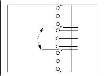
back of rack

 center-facing colums insert clip nuts
on first and third  holes between indicators
(center of rack)
rail “channel
insert clip nut
if column present
insert clip nuts
 between rack unit indicators
front-facing columns
Figure 1-3. Rack Column and Shelf Rail Orientation.
2. With the rail “channel” facing the center of the rack, connect the rail to the front facing column using a 1032 flathead screw (item 4) and the center clipon nut on the frontfacing column. Repeat for the rail on the opposite column. Ensure the rail channel faces the center of the rack.
If the rack has centerfacing columns (Figure 1- 3), insert a 1032 pan head screw through the rail opening and clip nut (perpendicular to the frontfacing column). Repeat for the rail on the opposite column.
3.On the rack’s rearfacing columns, insert clipon nuts on the first and third holes between the EIA unit indicators that are at the same vertical position as the indicators on the frontfacing columns.
4.Attach the rear brackets to the rail ends using two 1032 pan head screws (item 3) and two 1032 nuts with lockwashers (item 6) per rail. Adjust the bracket along the rail until the bracket end aligns with (covers) the rack’s rearfacing columns. Tighten the 1032 pan head screws to firmly connect the bracket to the rail and maintain the rail length.
Connect the rail brackets to the rearfacing columns using two 1032 pan head screws per column.
8 |
L4400 User’s Guide |
Introduction to the L4400 Series LXI Instruments 1
Install the Sliding Shelf
Facing the rack, slide the shelf (item 7) onto the bottom surfaces of the rail channels. The tabs at the back of the shelf pass underneath the channel surface. The tabs allow you to extend the shelf from the cabinet, thus providing a working surface for mounting the instruments.
Rail channel |
Shelf tab |
Bottom surface |
Figure 1-4. Installing the Shelf.
Install Instruments on the Shelf
The L4400 instruments can be installed flush (even) with front edge of the shelf, recessed in 50 mm increments, or reversemounted with the front of the instrument facing the back of the rack cabinet.
1.Extend the shelf from the rack such that approximately 50% - 75% of the shelf surface is outside of the rack. (The tabs on the back of the shelf that run underneath the rail channel prevent the shelf from tipping.)
2.Determine the position of the instruments (flush, recessed, reversed). To accommodate the terminal blocks (available with some of the L4400 instruments) and to simplify cable routing, it is recommended that the instruments be mounted flush (even) with the front or back edge of the shelf.
3.Note the location of the four mounting holes on the bottom of the instrument (Figure 1- 1). Set the carrier on the shelf, and align the mounting holes with the holes on the shelf. Insert four M4x8 flat head screws (item 1) upward through the bottom of the shelf and into the carrier mounting holes.
L4400 User’s Guide |
9 |
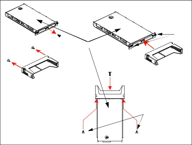
1Introduction to the L4400 Series LXI Instruments
4.Install the second L4400 instrument (if present) in the shelf area adjacent to the first instrument. If only one instrument is installed, install a filler panel on the front edge of the unused area. Insert two M4x8 flat head screws (item 1) upward through the bottom of the shelf and into the panel.
5.Connect the instrument power cord, LAN cable, and GPIB cable if present.
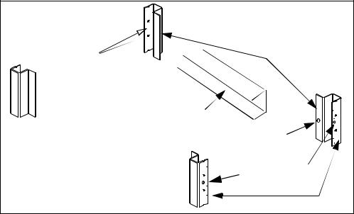
6.For instruments that have accompanying terminal blocks, partially remove the instrument subassembly from the instrument (carrier) by loosening the springloaded mounting screws (Figure 1- 5). Remove the support sleeve from the terminal block. Locate and remove the flat head screws from the sleeve and remove the pan head screw from between the instrument’s D- sub connectors (Figure 1- 5). Connect the sleeve to the instrument using the flat head and pan head screws as shown. Reconnect the subassembly.
|
spring-loaded |
|
mounting screws |
pan |
|
instrument sub-assembly |
|
flat head screws |
|
terminal block |
|
support sleeve |
pan head screw |
|
flat head screws |
Figure 1-5. Connecting the Terminal Block Support Sleeve.
10 |
L4400 User’s Guide |
Introduction to the L4400 Series LXI Instruments 1
|
Refer to Chapters 4-10 for information on Terminal Block wiring and |
|
NOTE |
||
connecting the terminal block to the instrument. |
||
|
||
|
|
Connect the Shelf to the Rack Frame
Once the instruments are installed and all power cords and cables are routed as intended, slide the shelf into the cabinet until the shelf handles meet the frontfacing columns of the rack frame. Using two1032 pan head dress screws (item 2) per column, secure the shelf to the frame.
Applying Power
The input power, operating environment, and storage environment specifications for the L4400 series instruments are listed in Table 1- 3. Refer to the instrument data sheets for a complete listing of instrument specifications. The data sheets can be found on the Web at:
www.agilent.com/find/L4400
Table 1-3. Agilent L4400 Series Instrument Input Power Specifications.
Instrument |
|
Description |
|
|
|
|
|
L4421A |
Power Supply: |
Universal 100V to 240V ±10% |
|
|
|
||
|
50Hz to 60Hz ±10% auto sensing |
||
L4433A |
Power Line Frequency: |
||
L4437A |
|
|
|
|
|
||
L4445A |
Power Consumption: |
50VA |
|
L4450A |
|
|
|
Operating Environment: |
Full accuracy for 0 C to 55 C |
||
L4451A |
|||
L4452A |
|
Full accuracy to 80% R.H. at 40 C |
|
|
|
|
|
|
Storage Environment: |
-40 C to 70 C |
|
|
|
|
Connecting the Power Cord and Turning On the Instrument
Connect the power cord supplied with the instrument or a power cord rated for the conditions listed in Table 1- 3 to the electrical outlet and to the instrument.
Turn the instrument on (and off) by pressing the power button shown in Figure 1- 6.
L4400 User’s Guide |
11 |

1 Introduction to the L4400 Series LXI Instruments
Refer to Table 3- 1 (Chapter 3) for definitions of the LEDs (ATTN, LAN, PWR) on the L4400 instrument front panel.
Power |
Figure 1-6. Location of the L4400 Series Instrument Power Button.
12 |
L4400 User’s Guide |

Agilent L4400 LXI Class C Instruments
User’s Guide


 2
2
Software Installation and Configuration
Installing the Agilent IO Libraries and L4400 Instrument Drivers 14
Configuring the L4400 Instruments 17
GPIB Configuration 33
Firmware Updates 39
Instrument Power-On and Default LAN Configuration States 45
This chapter contains the software installation and configuration procedures required for you to use the L4400 series instruments. Also included are procedures for configuring the LAN and (optional) GPIB interfaces, and for testing the communication (IO) paths to the instruments.
Agilent Technologies |
13 |
2 Software Installation and Configuration
Installing the Agilent IO Libraries and L4400 Instrument Drivers
Communication and control of the L4400 series instruments from a Microsoft® programming environment is provided through the following software that is included with the L4400A instruments:
•Agilent E2094A IO Libraries Suite 14.1
•Agilent L4400A Product Reference CDROM (p/n 3498913601)
This section covers the sequence and procedures for installing the IO libraries and instrument drivers required to program the instruments.
Installing the Agilent IO Libraries
The Agilent IO Libraries Suite must be installed first, followed by the L4400 instrument drivers that are located on the Product Reference
CDROM (p/n 3498913601). The IO Libraries are contained on the Agilent AutomationReady CD included with the instrument, or may be downloaded from the Agilent website at http://www.agilent.com/find/iosuite.
Before installing the IO libraries, review table 2- 1 to verify that your computer meets the specifications required by the software.
Table 2-1. Agilent IO Libraries Suite System Requirements.
Processor |
450 MHz Intel Pentium® II or higher |
|
|
Operating System |
Windows XP Professional or Home Edition (Service Pack 1 or |
|
later |
|
Windows 2000 Professional (Service Pack 4 or later) |
|
|
Web Browser |
Microsoft Internet Explorer 5.01 or greater (recommended) |
|
|
Available Memory |
128 MB (256 MB or greater recommended) |
|
|
Available Disk Space |
225 MB required for installation: |
|
- 160 MB for Microsoft .NET Framework |
|
- 65 MB for Agilent IO Libraries Suite |
|
|
|
175 MB required for operation: |
|
- 110 MB for Microsoft .NET Framework |
|
- 65 MB for Agilent IO Libraries Suite |
|
|
Video |
Super VGA (800x600) with 256 colors |
|
|
14 |
L4400 User’s Guide |

Software Installation and Configuration |
2 |
Close all applications on your computer. Insert the Agilent
AutomationReady CD into the CDROM drive. Follow the instructions as prompted during the installation. Accept all default directories specified.
If the IO libraries installation does not start automatically, select Start > Run from the Windows Start menu and type <drive>:\autorun\auto.exe where <drive> is the designator of the CDROM drive.
|
If another vendor’s implementation of VISA (Virtual Instrument |
|
NOTE |
||
Software Architecture) is currently installed on your computer, continue |
||
|
||
|
installation of the Agilent IO Libraries by installing Agilent VISA in |
|
|
side-by-side mode. More information on side-by-side operation can be |
|
|
found in the Agilent IO Libraries Suite Help (available after installation |
|
|
is complete) under “Using Agilent VISA with Another Vendor’s VISA. |
|
|
|
|
Installing the Agilent IO Libraries also installs the Interchangeable |
|
NOTE |
||
Virtual Instrument (IVI) Shared Components. The IVI Shared |
||
|
||
|
Components are required before IVI drivers (e.g. IVI-COM, IVI-C) can |
|
|
be installed (see “Installing the L4400 Instrument Drivers”). |
|
|
|
After the IO libraries have been successfully installed, you will see the Agilent IO Control (IO icon) in the taskbar notification area of your computer screen (Figure 2- 1).
Figure 2-1. Agilent IO Control Icon.
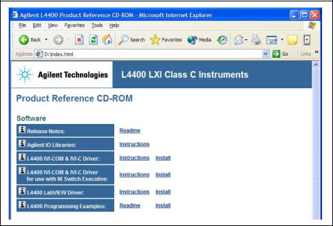
Installing the L4400 Instrument Drivers
Insert the L4400 Product Reference CD-ROM into the computer. The installation program will open the menu window shown in Figure 2-2. If the program does not start automatically, select Start -> Run -> Open: <cd-rom drive>:\index.html.
L4400 User’s Guide |
15 |
2 Software Installation and Configuration
Figure 2-2. L4400 Product Reference CD-ROM Software (Driver) Menu
Install the appropriate driver from the menu based on the environment you will use to program the L4400 instruments. Table 2-2 contains a list of common environments and corresponding drivers. Accept all default directories specified during installation.
Table 2-2. L4400 Programming Environments and Recommended Drivers
Programming Environment |
Recommended Drivers |
|
|
Microsoft® Visual C 6.0 Visual C++, ANSI C |
IVI-C, IVI COM, VISA |
|
|
Microsoft® Visual Basic 6.0 |
IVI-COM, VISA, VISA-COM |
|
|
Microsoft Visual Studio .NET for C#, C, |
IVI-COM |
Visual Basic |
|
|
|
Agilent VEE |
IVI-COM |
|
|
National Instruments LabVIEW |
LabVIEW Plug&Play (with |
|
L44XX native mode driver), |
|
IVI-C |
|
|
National Instruments LabWindows/CVI |
IVI-C |
|
|
For information on firmware updates that may be available after purchase, refer to “Firmware Updates” at the end of this chapter.
16 |
L4400 User’s Guide |
Software Installation and Configuration |
2 |
Configuring the L4400 Instruments
Instrument configuration as applied to the L4400 series of LXI instruments involves the following:
•identifying the IP address and host name (LAN programming)
•(optional) setting the GPIB address
•testing the communication paths (LAN and/or GPIB) to the instrument
•opening the Web interface to the instrument
Each task listed above is accomplished using the Agilent Connection
Expert Feature of the Agilent IO Libraries Suite.
The information included this section of the chapter is:
•Selecting a LAN Network
•Connecting the LAN Cables
•Configuring the LAN Interface
•GPIB Configuration
Selecting a LAN Network
This user’s guide defines a private (isolated) LAN as a network in which instrument access is limited to a direct connection between the computer and the instrument, or to multiple instruments connected via a dedicated router or switch. A site (companywide) LAN is defined as a network in which instrument access is available to many users in onsite and remote locations.
The instrument’s application and/or your company’s Information Technology (IT) department may have guidelines that help decide the type (private or site) of network used. If a network configuration has not been determined, refer to the following considerations concerning each type.
Private LAN Considerations
Some of the basic parameters of a private LAN network to consider are: security, performance, reliability, and IP address availability.
L4400 User’s Guide |
17 |
2 Software Installation and Configuration
Security: a private network generally involves direct connections between the computer and the instruments, and may include switches and routers. Access to the instrument is limited to users connected directly to the private network, as opposed to users on a site network that could locate and access the instrument from any location - possibly disrupting tests in progress. Code generation for test systems on a private network is often simplified as protection against unauthorized users may not be required.
Performance: test systems where large amounts of data are transferred usually have faster throughput on a private network. On a site network, heavy and unpredictable LAN traffic (lots of data) affects each instrument (node) on the network. The impact on a test system is that repeatability is difficult to achieve as latencies are difficult to account for.
Reliability: private networks are fundamentally more reliable than site networks as they host fewer users and are less complex than site networks. Private networks are isolated from conditions that could bring down (crash) a site network.
IP Address Availability: Every instrument (node) on a LAN (private or site) has an IP (Internet Protocol) address. Due to the expanding use of the internet, the number of site network IP addresses available is limited. By using a router with Dynamic Host Configuration Protocol (DHCP) capability on a private network, the router can assign an IP address to each instrument thus creating a subnetwork (subnet) that does not consume site IP addresses.
Site LAN Considerations
For applications requiring access by many users or by users at distributed sites, a site LAN network is required. In addition to supporting multiple users, site LANs often offer the advantage of being maintained by IT departments.
When using a site LAN, consult your IT department regarding all LAN configuration and security issues.
Connecting the LAN Cables
LAN cables are connected to the LAN terminal on the instrument, the computer, and to the router or switch if they are part of your network.
18 |
L4400 User’s Guide |
Loading...