

Page 1

Agilent Technologies
E8285A CDMA Mobile Station Test Set
Reference Guide
Firmware Version A.05.00 and Above
Agilent Part Number: E8285-90016
Printed in U. S. A.
June 2000
Rev. C
1
Page 2

© Copyright Agilent Technologies 1999, 2000
Notice Information contained in this document is subject to change without notice.
All Rights Reserved. Reproduction, adaptation, or translation wit hout prior wri tten
permission is prohibited, except as allowed under the copyright laws.
This material may be reproduced by or for the U.S. Government pursuant to the
Copyright License under the clause at DFARS 52.227-7013 (APR 1988).
Agilent Technologies
Learning Products Department
24001 E. Mission
Liberty Lake, WA 99019-9599
U.S.A.
2
S:\agilent\e8285\REFGUIDE\MANUAL\frntmt.fb
Page 3

Manufacturer’s Declaration
This statement is pr ovi ded to comply with the req uir ements of the German Sound
Emission Directive, from 18 January 1991.
This product has a sound pressure emission (at the operator position) < 70 dB(A).
• Sound Pressure Lp < 70 dB(A).
• At Operator Position.
• Normal Operation.
• According to ISO 7779:1988/EN 27779:1991 (Type Test).
Herstellerbescheinigung
Diese Information steht im Zusammenhang mit den Anforderungen der
Maschinenlärminformationsverordnung vom 18 Januar 1991.
• Schalldruckpegel Lp < 70 dB(A).
• Am Arbeitsplatz.
• Normaler Betrieb.
• Nach ISO 7779:1988/EN 27779:1991 (Typprüfung).
3
Page 4

Safety
Considerations
GENERAL
This product and related do cumentatio n must be reviewe d for familiar ization wi th
safety markings and instructions before operation.
This product has been designed and tested in accordance with IEC Publication
1010, "Safety Requirements for Electronic Measuring Apparatus," and has been
supplied in a safe condition. This instruction documentation contains information
and warnings which must be followed by the user to ensure safe operation and to
maintain the product in a safe condition.
SAFETY EARTH GROUND
A uninterruptible safety earth ground must be provided from the main power
source to the product input wiring terminals, power cord, or supplied power cord
set.
CHASSIS GROUND TERMINAL
T o preve nt a po tenti al shock hazard , always con nect t he rea r - panel c hassi s groun d
terminal to e arth ground when operating t his instrument from a dc power source.
SAFETY SYMBOLS
Indicates instrument damage can occur if indicated operating limits are exceeded.
!
Indicates hazardous voltages.
Indicates earth (ground) terminal
WARNING
A WARNING note denotes a hazard. It calls attention to a procedure,
practice, or the like, which, if not correctly performed or adhered to, could
result in personal injury. Do not proceed beyond a WARNING sign until the
indicated conditions are fully understood and met.
CAUTION
A CAUTION note denotes a hazard. It calls attention to an operation procedure,
practice, or the like, which, if not correctly performed or adhered to, could result
in damage to or destruction of part or all of the product. Do not proceed beyond
an CAUTION note until the indicated conditions are fully u nderstood and met.
4
S:\agilent\e8285\REFGUIDE\MANUAL\frntmt.fb
Page 5

Safety Considerations for this Instrument
WARNING This product is a Safety Clas s I instrument (provided with a protective
earthing ground incorporated in the power cord). The mains plug shall only
be inserted in a socket outlet provided with a protective earth contact. Any
interruption of the protective conductor inside or outside of the product is
likely to make the product dangerous. Intentional int erruption is
prohibited..
Whenever it is likely that the protection has been impaired, the instrument
must be made inoperative and be secured against any unintended operation.
If this instrument is to be energized via an autotransformer (for voltage
reduction), make sure the common terminal is connected to the earth
terminal of the power source.
If this product is not used as specified, the protection provided by the
equipment could be impaired. This product must be used in a normal
condition (in which all means for protection are intact) only.
No operator serviceable parts in this product. Refer servicing to qualified
personnel. To prevent electrical shock, do not remove covers.
Servicing instructions are for use by qualified personnel only. To avoid
electrical shock, do not perform any servicing unless you are qualified to do
so.
The opening of covers or removal of parts is likely to expose dangerous
voltages. Disconnect the product from all voltage sources while it is being
opened.
Adjustments described in the manual are performed with power supplied to
the instrument while protective covers are removed. Energy available at
many points may, if contacted, result in personal injury.
The power cord is connected to internal capacitors that my remain live for
5 seconds after disconnecting the plug from its power supply.
For Continued protection against fire hazard, replace the line fuse(s) only
with 250 V fuse(s) or the same current rating a nd type (for ex ample, normal
blow or time delay). Do not use repaired fuses or short circuited
fuseholders.
5
Page 6

WARNING: Always use the three-prong ac power cord supplied with this product. Failure to
ensure adequate earth grounding by not using this cord may cause product damage.
This product is design ed for use in Installation Category II and Pollution
Degree 2 per IEC 1010 and IEC 664 respectively. FOR INDOOR USE
ONLY.
This product has autoranging line voltage input, be sure the supply voltage
is within the specified range.
To prevent electrical shock, disconnect instrumen t from mains (line) before
cleaning. Use a dry cloth or one slightly dampened with water to clean the
external case parts. Do not attempt to clean internally.
Ven til ation Requirements: When installing the product in a cabinet, the
convection into and out of the product must not be restricted. The ambient
temperature (outside the ca bine t) must b e less t ha n th e maximum o perating
temperature of the product by 4° C for every 100 watts dissipated in the
cabinet. If the total power dissipated in the cabinet is greater than 800 watts,
then forced convection must be used.
Product
Markings
CE - the CE mark is a registered trademark of the European Community. A CE
mark accompanied by a year indicated the year the design was proven.
CSA - the CSA mark is a registered trademark of the Canadian Standards
Association.
6
S:\agilent\e8285\REFGUIDE\MANUAL\frntmt.fb
Page 7

Agilent Technologies Warranty Statement for Commercial Products
Agilent
Technologies
E8285A CDMA
Mobile Station
Test Set
Duration of
Warranty: 1 year
1. Agilent Technologies warrants Agilent Technologies hardware, accessories and
supplies against defects in materials and workmanship for the period specified above.
If Agilent Technologies receives notice of such defects during the warranty period,
Agilent Technologies will, at its option, either repair or replace products which prove
to be defective. Replacement products may be either new or like-new.
2 Agilent Technologies warrants that Agilent Technologies software will not fail to exe-
cute its programming instructions, for the period specified above, due to defects in material and workmanship when properly installed and used. If Agilent Technologies
receives notice of such defects during the warranty p e riod, Agilent Technologies will
replace software media which does not execute its programming instructions due to
such defects.
3. Agilent Technologies does not warrant that the operation of Agilent Technologies
products will be uninterrupted or error free. If Agilent Technologies is unable, within a
reasonable time, to repair or replace any product to a condition as warranted, customer
will be entitled to a refund of the purchase price upon prompt return of th e product.
4 Agilent Technologies pr oducts may cont ain remanufactur ed parts equival ent to new in
performance or may have been subject to incidental use.
5. The warranty period begins on the date of delivery or on the date of installation if
installed by Agilent Technologies. If customer schedules or delays Agilent
Technologies installation more than 30 days after delivery, warranty begins on the 31st
day from deli very.
6 Warranty does not apply to defects resulting from (a) improper or inadequate mainte-
nance or calibration, (b) software, interfacing, parts or supplies not supplied by Agilent
Technologies, (c) unauthorized modification or misuse, (d) operation outside of the
published environmental specifications for the product, or (e) improper site preparation
or maintenance.
7 TO THE EXTENT ALLOWED BY LOCAL LAW, THE ABOVE WARRANTIES
ARE EXCLUSIVE AND NO OTHER WARRANTYOR CONDITION, WHETHER
WRITTEN OR ORAL IS EXPRESSED OR IMPLIED AND AGILENT TECHNOLOGIES SPECIFICALLY DISCLAIMS ANY IMPLIED WARRANTIES OR CONDITIONS OR MERCHANTABILITY, SATISFACTORY QUALITY, AND FITNESS
FOR A PARTICULAR PURPOSE.
7
Page 8

8 Agilent Technologies will be liable for damage to tangible property per inciden t up to
the greater of $300,000 or the actual amount paid for the product that is the subject of
the claim, and for damages for bodily injury or death, to the extent that all such damages
are determined by a court of competent jurisdiction to have been directly caused by a
defective Agilent Technologies product.
9 TO THE EXTENT ALLOWED BY LOCAL LAW, THE REMEDIES IN THIS WAR-
RANTY STATEMENT ARE CUSTOMER’S SOLE AND EXCLUSIVE REMEDIES.
EXCEPT AS INDICATED ABOVE, IN NO EVENT WILL AGILENT TECHNOLOGIES OR ITS SUPPLIERS BE LIABLE FOR LOSS OF DATA OR FOR DIRECT,
SPECIAL, INCIDENTAL, CONSEQUENTIAL (INCLUDING LOST PROFIT OR
DATA), OR OTHER DAMAGE, WHETHER BASED IN CONTRACT, TORT, OR
OTHERWISE.
FOR CONSUMER TRANSACTIONS IN AUSTRALIA AND NEW ZEALAND:
THE WARRANTY TERMS CONTAINED IN THIS STATEMENT, EXCEPT TO
THE EXTENT LAWFULLY PERMITTED, DO NOT EXCLUDE RESTRICT OR
MODIFY AND ARE IN ADDITION TO THE MANDATORY STATUTORY
RIGHTS APPLICABLE TO THE SALE OF THIS PRODUCT TO YOU.
ASSISTANCE Product maintenance agreements and other customer assistance agreements are
available for Agilent Technologies products. For any assistance, contact your
nearest Agilent Technologies Sales and Service Office.
8
S:\agilent\e8285\REFGUIDE\MANUAL\frntmt.fb
Page 9

DECLARATION OF CONFORMITY
according to ISO/IEC Guide 22 and EN 45014
Manufacturer’s Name:
Manufacturer’s Address:
Agilent Technologies
Spokane Division
24001 E. Mission Avenue
Liberty Lake, Washington 99019-9599
USA
declares that the product
Product Name:
Model Number:
Product Options:
CDMA Mobile Station Test Set
Agilent Technologies E8285A
All
conforms to the following Product specifications:
Safety: IEC 61010-1:1990+A1+A2 / EN 61010-1:1993+A2
EMC: CISPR 11:1990 / EN 55011:1991- Group 1, Class A
IEC 61000-3-2:1995 / EN 61000-3-2:1995
IEC 61000-3-3:1995 / EN 61000-3-3:1994
EN 50082-1 : 1992
IEC 801-2:1991 - 4kV CD, 8kV AD
IEC 801-3:1984 - 3 V/m
IEC 801-4:1988 - 0.5 kV Signal Lines,
1 kV Power Lines
Supplementary Information:
This product herewith complies with the requirements of the Low Voltage Directive
73/23/EEC and the EMC Directive 89/336/EEC and carries the CE-marking
accordingly.
Spokane, Wash i ng ton USA June 16, 1999
European Contact: Your local Agilent T e chnologies Sales and Service Office or Agilent Technologies GmbH
Department ZQ/Standards Europe, Herrenberger Strasse 130, D-71034 Böblinger, Germany (FAX+49-7031-14-3143)
Vince Roland
Reliability & Regulatory
Engineering Manager
9
Page 10

Agilent
Technologies
E8285A Support
Contacts
The documentation suppli ed wi th yo ur t es t se t i s an excellent source of ref er enc e,
applications, and service information. Please use these manuals if you are experiencing technical problems:
• Applications information is included in the Agilent Technologies E8285A CDMA
Mobile Station Test Set Application Guide ( E82 85-90019)
• Calibration and repair information are in the Agilent Technologies E8285A CDMA
Mobile Station Test Set Assembly Level Repair Manual (E8285-90033).
If you have used the manuals and still have application questions, contact your
local Agilen t Technologies Sales Representative.
Repair assistance is available for the Agilent Technologies E8285A CDMA Mobile Test
Set from the factory by phone and e-mail. Parts information is also available from Agilent
T echnolog ies.
When calling or writing for repair assistance, please have the following information ready:
• Instrument model number (Agilent Technologies E8285A)
• Instrument Serial Number (tag located on the rear panel).
• Installed options - if any (tag located on the rear panel).
• Instrument firmware revision (displayed at the top of the screen when the Test Set is
powered up, and is also displayed on the CONFIGURE screen).
Support Telephone
1 800 827 3848 (U.S. only)
1 509 921 3848 (International)
1 800 227 8164 (Agilent Technologies Direct Parts Ordering, U.S. only)
1 916 783 0804 (Agilent Technologies Service Parts Identification, U.S. & Intl.)
Electronic mail (Internet): Spokane_Service@spk.agilent.com
Numbers:
10
S:\agilent\e8285\REFGUIDE\MANUAL\frntmt.fb
Page 11

Table 1 Regional Sales and Service Offices
United States of America:
Agilent Technologies
Test and Measurement Call Center
P.O. Box 4026
Englewood, CO 80155-4026
(tel) 1 800 452 4844
Japan:
Agilent Technologies Japan Ltd.
Measurement Assist ance Center
9-1 Takakura-Cho, Hachioji-Shi,
Tokyo 192-8510, Japan
(tel) (81) 456-56-7832
(fax) (81) 426-56-7840
Asia Pacific:
Agilent Technologies
24/F, Cityplaza One,
111 Kings Road,
Taikoo Shing, Hong Kong
Canada:
Agilent Technologies Canada Inc.
5150 Spectrum Way
Mississauga, Ontario
L4W 5G1
(tel) 1 877 894 4414
Latin America:
Agilent Technologies
Latin America Region
Headquarters
5200 Blue Lagoon Drive,
Suite #950
Miami, Florida 33126
U.S. A.
(tel) (305) 267 4245
(fax) (305) 267 4286
Europe:
Agilent Technologies
European Marketing Organization
P.O. Box 999
1180 AZ Amstelveen
The Netherlands
(tel) (3120) 547 9999
Australia/New Zealand:
Agilent Technologies
Australia Pty Ltd.
347 Burwood Highway
Forest Hill, Victoria 3131
(tel) 1 800 629 485
(Australia)
(fax) (61 3) 9272 0749
(tel) 0 800 738 378
(New Zealand)
(fax) (64 4) 802 6881
(tel) (852) 3197 7777
(fax) (852) 2506 9233
11
Page 12

In this Book Throughout this manual the term "Test Set" is used to denote the Agilent
Technologies E8285A.
Test Set screens shown in this manual may not match those displayed on the Test
Set in every d etail.
Chapter 1, Key and Miscellaneous Knob Descriptions
This chapter describes func tions of the Test Set’s keys.
Chapter 2, Connector Descriptions
This chapter describes the Test Set’s connectors.
Chapters 3 Screen Descriptions
This chapters describe the T est Set’ s screens for CDMA testing and for analog
testing..
Chapters 4 Field Descriptions
This chapters describe the fields found on the Test Set’s screens for CDMA
testing and for analog testing.
12
S:\agilent\e8285\REFGUIDE\MANUAL\frntmt.fb
Page 13

Documentation
Map
All of the following literature, with the exception of the Instrument BASIC User’s
Handbook, is shipped with the Agilent T echno logies E8285A on a CD-ROM. The
Agilent part number of the CD-ROM is E8285-10004.
Unless a delete option is specified, paper versions of the Application Guide and
Condensed Programming Reference Guide are also shipped with each Test Set.
If option OBW is ordered, paper versions of the Reference Guide and the User’s
Guide will also be included with the Test Set.
Reference Guide (E8285-90016)
This guide describes the functions performed by each front panel key, front and rear
panel connector, and display screen and field. GPIB command examples for each display field are included.
User’s Guide (E8285-90018)
This guide provides a tuto rial-styl e overview of operat ing the Test Set, i ncluding a section designed to help you get started. Status reporting, IBASIC controller information,
and error message descriptions are also included.
Application Guide (E8285-90019)
1
This guide contains step-by-step procedures and programming examples for
calibrating the Test Set, setting up a c all, an d making mea surements on CDMA
and AMPS mobile stations. Tips for increasing measurement throughput are
also included, as well as a procedure for logging protocol messages.
Condensed Programming Reference Guide (E8285-90020)
This pocket-sized gu ide co ntain s a compl ete l ist ing of GPIB commands , alon g
with a cross-r eference between front-panel disp lay fields and the corresponding
commands.
Assembly Level Repair (E8285-90033)
This guide includes p rocedur es fo r perf orming period ic adj ustments, verif ying
performance, troubl eshooting, and repair ing the T est Set. Block diagrams an d a
list of replaceable parts are also included.
1. Part numbers listed are Agilent Technologies part numbers unless otherwise stated.
13
Page 14

Instrument Basic User’s Handbook (E2083-90000)
This guide contains a complete lis ting of I BASIC commands. Thi s guide is not
shipped with the Test Set. For ordering information, contact your nearest regional sales office.
Specifications (5968-8839E)
This document prov ides a short descriptio n of the Agile nt E8285A and lis ts the
operating specifications.
This document also includes the specifications for Agilent Technologies 83217A
Option 001, 003, and 004 software.
14
S:\agilent\e8285\REFGUIDE\MANUAL\frntmt.fb
Page 15

Contents
Description of Keys
Keys....................................................................................................................................................31
Address.................................................................................................................................................................. 31
Answer................................................................................................................................................................... 31
Assign.................................................................................................................................................................... 32
Average.................................................................................................................................................................. 32
Call/Page................................................................................................................................................................ 34
Cancel.................................................................................................................................................................... 34
EEX ....................................................................................................................................................................... 34
End/Release........................................................................................................................................................... 35
Enter ...................................................................................................................................................................... 35
Hold....................................................................................................................................................................... 35
IBASIC reset ......................................................................................................................................................... 35
Increment
K1 - K5, & K1’- K3’............................................................................................................................................. 39
Local...................................................................................................................................................................... 40
Low limit, High limit............................................................................................................................................. 40
Meas reset ............................................................................................................................................................. 44
Meter ..................................................................................................................................................................... 45
No Ratio W............................................................................................................................................................ 49
On/Off.................................................................................................................................................................... 49
POWER................................................................................................................................................................. 49
Preset..................................................................................................................................................................... 49
Previous................................................................................................................................................................. 49
Print ....................................................................................................................................................................... 50
Recall..................................................................................................................................................................... 50
Ref set.................................................................................................................................................................... 51
Register.................................................................................................................................................................. 54
Release................................................................................................................................................................... 54
Save ....................................................................................................................................................................... 54
Shift ....................................................................................................................................................................... 55
Yes On/Off........................... ...................... .... ... ...................... .... .... ... ...................... .... ....... ... .... ...................... .... .. 56
0 to 9, decimal point (.), +/-, and A to F................................................................................................................ 56
÷10, Increment set, Increment x10...... .... ... ............................................ .... ... ...................... .... ... .......... 36
Symbol Keys...................................................................................................................................... 57
Backspace.............................................................................................................................................................. 57
Down-Arrow, Up-Arrow....................................................................................................................................... 57
Units-of-Measure Keys......................................................................................................................................... 58
Miscellaneous Hardware....................................................................................................................59
Front Panel Knobs................................................................................................................................................. 59
Programmable Front-Panel Keys for Screens....................................................................................60
Non-Programmable Front-Panel Keys and Functions ....................................................................... 61
DATA FUNCTIONS Keys.............................................. ...................................................... ........ ..... 62
Guidelines for Using Measurement Data Functions ............................................................................................ 62
15
Page 16

Contents
Guidelines for Using Numeric Entry Field Data Functions ................................................................................. 63
USER Keys.........................................................................................................................................64
Description of Connectors
Connectors ..........................................................................................................................................67
ANTENNA IN........................ .... ... ...................... .... ... ...................... .... .... ... ...................... ......................... .... .... .. 67
AUDIO IN LOW, HIGH....................................................................................................................................... 68
AUDIO OUT......................................................................................................................................................... 69
AUD MONITOR OUTPUT.................................................................................................................................. 69
CELL SITE/TRIGGERS....................................................................................................................................... 70
CDMA CLOCK MUX OUTPUT......................................................................................................................... 71
COMPOSITE VIDEO .......................................................................................................................................... 71
DUPLEX OUT...................................................................................................................................................... 72
EVEN SEC INPUT............................................................................................................................................... 72
EXT REF INPUT.................................................................................................................................................. 73
GPIB ..................................................................................................................................................................... 73
MODULATION INPUT ...................................................................................................................................... 74
PAGING CHANNEL LOGGING (DCS2>)......................................................................................................... 74
PARALLEL PORT................................. ..................... .... .... ... ...................... .... ... .......................... ... .... . ................ 75
PROTOCOL SERIAL............................ ... ...................... .... ... ...................... .... ... .... ...................... ... ..................... 75
RF IN/OUT ........................................................................................................................................................... 76
SA TRIG OUTPUT........................................... ... .... ...................... ... .... .... ..................... .... .... ... .... ...................... .. 76
SERIAL PORT 9................................................................................................................................................... 77
SERIAL PORT 10................................................................................................................................................. 78
TRAFFIC CHANNEL LOGGING (DCS1>)....................................................................................................... 79
16X CHIP OUTPUT.......................... .... ... .... ...................... ... .... ...................... ... .... .... ......................... ................. 79
10 MHz OUTPUT..................................... .... .... ..................... .... .... ..................... .... .... ... ............................. .... ...... 80
Description of Screens
Adjacent Channel Power Screen.........................................................................................................82
How the Test Set Measures Adjacent Channel Power (ACP) .............................................................................. 83
AF Analyzer Screen............................................................................................................................84
AF Analyzer Block Diagram ............................... ...................... .... ... ...................... .... ... .... ......................... .... .... .. 85
Call Control Screens...........................................................................................................................86
Call Control Screens - ANALOG MEAS............................................................................................................. 87
Call Control Screens - AUTHENTICATION....................................................................................................... 89
Call Control Screens - CALL BIT........................................................................................................................ 90
Call Control Screens - CALL CONFIGURE........................................................................................................ 94
Call Control Screens - CALL DATA .................................................................................................................... 95
CDMA Authentication Screen............................................................................................................99
CDMA Call Control Screen................................................................................................................100
CDMA Cell Site Configuration Screen ............................................................................................. 101
CDMA Cellular Mobile Receiver Test Screen....................................................................................102
16
Page 17

Contents
CDMA Cellular Mobile Receiver Block Diagram.............................................. .... .... ... ...................... .... ... .......... 103
CDMA Cellular Mobile Transmitter Test Screen ..............................................................................104
CDMA Gated Power Screen..............................................................................................................105
CDMA Generator Control Screen...................................................................................................... 106
CDMA Generator Control Block Diagram........................................................................................................... 107
CDMA Mobile Reported FER Screen ............................................................................................... 108
CDMA Mobile Reported Pilot Strength Screen ................................................................................ 109
CDMA Open Loop Time Response Screen....................................................................................... 110
CDMA Reverse Channel Spectrum Screen ....................................................................................... 111
CDMA Short Message Service Screen..............................................................................................112
CDMA Swept Power Measurement Screen ......................................................................................113
CDMA Transmitter Power Range Test Screen .................................................................................. 114
Configure Screen................................................................................................................................115
Duplex Test Screen............................................................................................................................. 116
Duplex Test Block Diagram .................................................................................................................................. 117
Help Screens....................................................................................................................................... 118
I/O Configure Screen ......................................................................................................................... 119
Message Screen.................................................................................................................................. 120
Oscilloscope Screens..........................................................................................................................121
Selecting the Oscilloscope’s Input ........................................................................................................................ 122
Print Configure Screen.......................................................................................................................123
RF Analyzer Screen ........................................................................................................................... 124
RF Analyzer Block Diagram................................................................................................................................. 125
RF Generator Screen.......................................................................................................................... 126
RF Generator Block Diagram................................................................................................................................ 127
RX Test Screen...................................................................................................................................128
RX Test Block Diagram........................................................................................................................................ 129
Service Screen....................................................................................................................................130
Spectrum Analyzer Screens ............................................................................................................... 131
Using the Spectrum Analyzer................................................................................................................................ 132
TESTS Screens................................................................................................................................... 133
Description of the Tests Subsystem....................................................................................................................... 133
TESTS (Main Menu)............................................................................................................................................. 134
TESTS (Channel Information).............................................................................................................................. 135
TESTS (Test Parameters)...................................................................................................................................... 136
17
Page 18

Contents
TESTS (Order of Tests)......................................................................................................................................... 137
TESTS (Pass/Fail Limits)..................................................................................................................................... 138
TESTS (Save/Delete Procedure)........................................................................................................................... 139
TESTS (Executions Conditions)........................................................................................................................... 140
TESTS (External Devices).................................................................................................................................... 141
TESTS (Printer Setup) .......................................................................................................................................... 142
TESTS (IBASIC Controller)................................................................................................................................. 143
TX TEST Screen.................................................................................................................................144
TX Test Bloc k Diag ra m................................ .... ... ...................... .... ... .... ...................... ... .... ......................... .... .... .. 145
Description of Fields
Fields...................................................................................................................................................148
Abort Print.............................................. ... .... .... ..................... .... .... ..................... .... .... ....... .... ... ...................... .... .. 148
Access (annunciator)............................................................................................................................................. 148
Acc Prb Pwr.......................................................................................................................................................... 149
Access Probe (annunciator)................................................................................................................................... 151
AC Level .............................................................................................................................................................. 151
Active.................................................................................................................................................................... 152
Active (annunciator).............................................................................................................................................. 153
ACP Meas............................................................................................................................................................. 153
Add Intcpt.................. ... ...................... .... ... ...................... .... ... .... ...................... ... .... .............................................. 154
Addr ...................................................................................................................................................................... 154
AF Anl In ................................ .... ... .... ...................... ... .... ...................... .... ... ............................. .... ...................... .. 155
AF Cnt Gate .................................. ...................... .... ... .... ...................... .... ... ............................. ............................ 155
AF Freq ................................ ..................... .... .... ... ...................... .... ... ...................... .... ........... ..................... .... .... .. 156
AF Freq ................................ ..................... .... .... ... ...................... .... ... ...................... .... ........... ..................... .... .... .. 157
AFGen1 Freq .............................. ... ...................... .... ... ...................... .... .... ... ............................................... .... .... .. 157
AFGen1 Lvl ...................................... .... ..................... .... .... ... ...................... .... ... ............................. .... ................. 157
AFGen1 T o....................... .... ... ...................... .... ... ...................... .... ... .... ...................... ... ........ ....... ... ..................... 158
AFGen2 Freq .............................. ... ...................... .... ... ...................... .... .... ... ............................................... .... .... .. 158
AFGen2 T o....................... .... ... ...................... .... ... ...................... .... ... .... ...................... ... ........ ....... ... ..................... 159
A_Key .................................................................................................................................................................. 160
A-Key Digits.................................. ...................... .... ... .... ...................... .... ... ............................................... .... .... .. 161
Alert................... .... .... ..................... .... .... ... ...................... .... ... ...................... .... ... ................................. .... ... .......... 162
All Chans? ....................... ........................................... .... .... ...................... ... .... ................................ ..................... 162
Alt Pwr Ms Cal Bands .......................................................................................................................................... 163
AM Depth.............................................................................................................................................................. 164
Ampl Error............................................................................................................................................................ 164
Amplitude.............................................................................................................................................................. 165
Amplitude (CDMA Swept Power Measuremen t) ....................................... .... ... .... ...................... ... .... ................. 166
Answer Mode............................................ .... .... ..................... .... .... ... ...................... .... ... ........ ... .... ... ..................... 166
Antenna In ................... .... ........................................... .... .... ...................... ... .... ..................................................... 167
Arm ........................................................... .... .... ..................... .... .... ... ...................... ............... ..................... .... .... .. 167
Attack Time........................................................................................................................................................... 168
Atten Hold ............................................................................................................................................................ 169
18
Page 19

Contents
Audio In Lo .......................................................................................................................................................... 169
Audio Out ............................................................................................................................................................. 170
Authen ................................................................................................................................................................... 170
Authen Data Clear................................................................................................................................................. 171
Authentication Data Table..................................................................................................................................... 171
Authent ................................................................................................................................................................. 176
Auto/Norm ............................................................................................................................................................ 176
Autostart Test Procedure on Power-Up ................................................................................................................ 177
Auto Zero...................... .... ... ...................... .... ... ...................... .... .... ..................... .... .... ......................... .... ... .......... 177
Averages ............................................................................................................................................................... 178
Avg Power ............................................................................................................................................................ 178
AWGN................................................................................................................................................................... 181
Band Class............................................................................................................................................................. 182
Base Freq (User Defined)...................................................................................................................................... 183
Base ID.................................................................................................................................................................. 184
Beeper ................................................................................................................................................................... 184
BER Thresh........................................................................................................................................................... 185
Burst Time............................................................................................................................................................. 186
BW= ...................................................................................................................................................................... 187
by # errors.................................... ... ...................... .... ... .... ...................... ... .... ............................. .... ... ..................... 187
by # frames................... .... ... ...................... .... ... ...................... .... .... ... ...................... .... .......... ........ ... ..................... 188
Called Number: .................................................................................................................................................... 188
Calling Name ........................................................................................................................................................ 189
Call Limit...................... .... ...................... ... .... ...................... ... .... ...................... ... .... ....... .... ... ................................ 189
Call Status......................... ... ...................... .... ... ...................... .... .... ..................... .... ........... ...................... ... .... ...... 190
Carrier ................................................................................................................................................................... 191
Carrier Ref ............................................................................................................................................................ 191
CC Order ........................................ ...................... .... ... ...................... .... ... .... .......................... ... .... ........................ 192
Center Freq (Analog)............................................................................................................................................. 192
Center Freq (CDMA)............................................................................................................................................ 193
Change ................................................................................................................................................................... 193
Chan: -....................... ..................... .... .... ... ...................... .... ... ...................... .... ... .... ....... .... ... ................................ 194
Channel (CDMA to Analog or Interband Handoffs)............................................................................................. 195
Channel BW ......................................................................................................................................................... 196
Chan Power ........................................................................................................................................................... 197
Chan Power Meas Intrvl........................................................................................................................................ 198
Chan Std................................................................................................................................................................ 199
Check .................................................................................................................................................................... 199
Check Digits.......................................................................................................................................................... 200
Ch Loc:.................................................................................................................................................................. 201
Ch Offset ............................................................................................................................................................... 202
Chan Space (User Defined) .................................................................................................................................. 202
Closed Loop Pwr Cntl........................................................................................................................................... 203
Clr Scr ................................. ...................... .... ... ...................... .... .... ..................... .... ............................. .... ... .......... 204
CMAX .................................................................................................................................................................. 204
Cntl Chan............................................................................................................................................................... 205
19
Page 20

Contents
Cnfg (External Devices) .......................................... ... .... .... ...................... ... .... ............................................... .... .. 205
Cntry Code............................................................................................................................................................ 206
Code Location ...................................................................................................................................................... 206
Confidence............................................................................................................................................................ 207
Connect (annunciator)........................................................................................................................................... 209
Connected (annunciator)....................................................................................................................................... 210
Continue ............................................................................................................................................................... 210
Cont/Single ........................................................................................................................................................... 211
Controls (CDMA Gated Power)............................................................................................................................ 211
Controls (CDMA Reverse Channel Spectrum)..................................................................................................... 211
Controls (CDMA Swept Power Measurement) ................................................................................................... 212
Controls (Open Loop T im e Respon se)...... .... ...................... ... .... .... ..................... .... .... .......................................... 212
Controls (Oscilloscope)......................................................................................................................................... 213
Controls (Spectrum Analyzer) .............................................................................................................................. 213
Current .................................................................................................................................................................. 213
Data Length .......................................................................................................................................................... 214
Data Mode............................................................................................................................................................. 214
Data Rate .............................................................................................................................................................. 215
Data Spec .............................................................................................................................................................. 216
Data Ty pe .............................................................................................................................................................. 217
Date ...................................................................................................................................................................... 218
DC Current ........................................................................................................................................................... 218
DC Level .............................................................................................................................................................. 219
De-Emp Gain ........................................ ... ...................... .... ... ...................... .... ... .... ......................... .... .... ... .......... 220
De-Emphasis ........................................................................................................................................................ 220
Delete Ch .............................................................................................................................................................. 220
Delet Ins ............................................................................................................................................................... 221
Delet Stp ............................................................................................................................................................... 221
Description ........................................................................................................................................................... 221
Detector ................................................................................................................................................................ 222
Disarm ................................................................................................................................................................... 223
Display .................................................................................................................................................................. 223
Display Interim Results......................................................................................................................................... 231
Display User Mssgs............................................................................................................................................... 231
Display Word ........................................................................................................................................................ 232
Distn ..................................................................................................................................................................... 236
Drop Intcpt................... .... .... ..................... .... .... ..................... .... .... ... ...................... .... ....... .... ....... ... ..................... 237
Drop Timer........................................................ ... .... ...................... ... .... ...................... ........... ......................... .... .. 238
DSAT............................ ...................... .... ... .... ...................... ... .... ...................... ... .... ............................. .... ... .... ...... 239
DSAT/DST (hex)................................................................................................................................................... 240
DSAT Meas .......................................................................................................................................................... 241
Duplex Out ........................................................................................................................................................... 242
Duplicate User Data ............................................................................................................................................. 242
Eb/Nt..................................................................................................................................................................... 243
Echo Delay........................... ... ...................... .... ... ...................... .... ... .... ...................... .......................................... 243
Encoding ..................................... ...................... ... .... ... ...................... .... .... ............................................... ... .... .... .. 244
20
Page 21

Contents
Enter ASCII Data .................................................................................................................................................. 245
Enter Hex Data...................................................................................................................................................... 245
Enter Procedure Filename .................................................................................................................................... 246
Errors..................................................................................................................................................................... 246
Errors Counted....................................................................................................................................................... 247
Esc Mode............................................................................................................................................................... 248
ESN (dec): ............................................................................................................................................................ 248
ESN (hex): ............................................................................................................................................................ 249
ESN ....................................................................................................................................................................... 249
Execute (Handoff) ................................................................................................................................................. 250
Execute (Closed Loop Power Control Change)................................ .... ........................................... .... ................. 251
Exec (Execution Cond) .................. ...................... .... ... ...................... .... ... .... ...................... .......................... ... .... .. 251
Expected...................................... ........................................... .... .... ..................... .... .... .............. ...................... .... .. 251
Expected PN Offset............................................................................................................................................... 252
Expected Strength.................................................................................................................................................. 253
Expected T_Add.................................................................................................................................................... 254
Expected T_Drop................................................................................................................................................... 255
External Disk Specification ..................................... ...................... ... .... ...................... ... .... ................................... 256
Ext Load R ............................................................................................................................................................ 256
Ext NGHB ............................................................................................................................................................ 257
FER........................................................................................................................................................................ 258
FER Report (Clear)................................................................................................................................................ 259
FER Spec............................................................................................................................................................... 259
FF at End .............................................................................................................................................................. 259
FF at Start ............................................................................................................................................................. 260
Filter 1 .................................................................................................................................................................. 260
Filter 2 .................................................................................................................................................................. 260
Firmware ............................................................................................................................................................... 261
Flow Cntl .............................................................................................................................................................. 261
FM Coupling ......................................................................................................................................................... 261
FM Deviation......................................................................................................................................................... 262
FM Deviation (Call Control)................................................................................................................................. 262
Frame Clock.......................................................................................................................................................... 263
Frames ................................................................................................................................................................... 264
Frames Counted..................................................................................................................................................... 264
Freq (Channel Information) .................................................................................................................................. 265
Freq Error (CDMA)............................................................................................................................................... 265
Freq Error (Analog)............................................................................................................................................... 266
Frequency (Analog)............................................................................................................................................... 267
Gate Time.............................................................................................................................................................. 268
Gain Cntl ............................................................................................................................................................... 268
(Gen)-(Anl)............................................................................................................................................................ 269
Grid........................................................................................................................................................................ 269
Grid (CDMA Swept Power Measurement) .......................................................................................................... 270
Handoff.................................................................................................................................................................. 270
Handoff.................................................................................................................................................................. 271
21
Page 22

Contents
Hard Handoff (annuncia tor)................................. ...................... .... ... .... ...................... ... .... ............................. .... .. 271
GPIB Adrs............................................................................................................................................................. 272
IBASIC Echo ........................................................................................................................................................ 272
IBASIC (IBASIC Cntrl)........................................................................................................................................ 272
Ideal Mobile Power....................................... .... ... .... ...................... ... .... ...................... ... .... ........... ... ..................... 273
IF Filter ................................................................................................................................................................. 274
If Unit-Under-Test Fails..................... .... ..................... .... .... ... ...................... .... ... .......................... ... ..................... 274
Init Power.............................................................................................................................................................. 274
Input Att ............................................................................................................................................................... 275
Input Atten ............................................................................................................................................................ 276
Input Gain.............................................................................................................................................................. 277
Input Port............................................................................................................................................................... 278
Insert Ch................................................................................................................................................................ 279
Insrt Ins.................................................................................................................................................................. 279
Insrt Stp................................................................................................................................................................. 280
Inst Echo................................................................................................................................................................ 280
Inst# ...................................................................................................................................................................... 280
Internal.................................................................................................................................................................. 281
Keep ...................................................................................................................................................................... 281
Length .................................................................................................................................................................. 282
Level (div)............................................................................................................................................................. 283
Library................................................................................................................................................................... 283
Lines/Page............................................................................................................................................................. 283
Lower and Upper ACP [Ratio:Level]................................................................................................................... 283
Lower Limit .......................................................................................................................................................... 284
Lvl (CDMA Gated Power).................................................................................................................................... 284
Lvl (Open Loop Time Resp on se)........................................... .... .... ..................... .... .... ... ............................. .......... 285
Main Menu............................................................................................................................................................ 285
Marker: Freq.......................................................................................................................................................... 286
Marker Lvl (CDMA Swept Power Measurement) ............................................................................................... 286
Marker: Lvl........................................................................................................................................................... 287
Marker: Norm/Delta.............................................................................................................................................. 288
Marker: Time......................................................................................................................................................... 288
Marker Pos (CDMA Reverse Channel Spectrum)................................................................................................ 289
Marker Time (CDMA Gated Power).................................................................................................................... 289
Marker Time (Open Loop Time Response).......................................................................................................... 290
Marker Time (CDMA Swept Power Measurement) ............................................................................................ 290
Marker To:............................................................................................................................................................. 291
Marker To: ............................................................................................................................................................ 291
Mask Ty pe ............................................................................................................................................................ 292
Max Frames........................................................................................................................................................... 292
Max Power............................................................................................................................................................ 293
Max Req Seq, Max Rsp Seq ................................................................................................................................. 294
Max Slot Cycle Index............................................................................................................................................ 294
Meas Cntl.............................................................................................................................................................. 295
Message Data Mode.............................................................................................................................................. 295
22
Page 23

Contents
Mic Pre-Emp ........................................................................................................................................................ 296
Min Power...................................... .... ...................... ... .... ...................... ... .... .... ................................ ..................... 296
Min/Max Pwr............. ... .... ... ...................... .... ... ...................... .... .... ..................... .... .... ... ........... .... ...................... .. 297
Mobile Parm.......................................................................................................................................................... 298
Mobile Power Mode.............................................................................................................................................. 299
Mobile Pwr............................................................................................................................................................ 300
Mode...................................................................................................................................................................... 300
Model..................................................................................................................................................................... 300
Model:.................................................................................................................................................................... 301
Mod In To ............................................................................................................................................................. 301
MS Id..................................................................................................................................................................... 302
MS Ack Cause Code: ........................................................................................................................................... 303
MS Ack Rcvd (annunciator).................................................................................................................................. 305
MS Database.......................................................................................................................................................... 306
MS FER................................................................................................................................................................. 307
MS FER Report Interval........................................................................................................................................ 308
MS ID.................................................................................................................................................................... 308
Network ID............................................................................................................................................................ 310
Netwrk Code.......................................................................................................................................................... 310
NGHB Fq (Ch) ..................................................................................................................................................... 311
Nom Power................... ............................................ ... .... ...................... ... .... ................................. ... ..................... 312
Nom Pwr Ext.............................................................................. .... ... ...................... .... ... ....... ...................... .... .... .. 312
No Pk/Avg ............................................................................................................................................................ 313
Normalize ............................................................................................................................................................. 314
Notch Freq............................................................................................................................................................. 315
Notch Gain............................................................................................................................................................. 315
Notch Coupl........................................................................................................................................................... 316
Num of Bits ................................. ... .... .... ..................... .... .... ..................... .... .... .......................... ........................... 316
Num Pages..................................................... ... .... ...................... .... ... ...................... .... .......... .... .... ...................... .. 317
Num Step............................. .... .... ..................... .... .... ...................... ... .... ... ............................. . ..................... .... .... .. 317
OCNS (Sector A Power) .................................. .... .... ...................... ... .... ...................... ... .... ... .... ............................ 318
OCNS (Sector B Power).............................................. .... .... ..................... .... .... ... ............................................ .... .. 319
Offset Freq................................... ..................... .... .... ... ...................... .... ... ............................. ...................... .... .... .. 319
Open Loop Time Response (Execute) .................................................................................................................. 320
Options .................................................................................................................................................................. 320
Order...................................................................................................................................................................... 321
Orig Addr............................................................................................................................................................... 322
Output Atten Hold................................................................................................................................................. 323
Output Heading:.................................................................................................................................................... 323
Output Port............................................................................................................................................................ 324
Output Results For................................................................................................................................................. 324
Output Results To .................................................................................................................................................. 325
Page ....................................................................................................................................................................... 325
Page (annunciator)................................................................................................................................................. 326
Page Rate............................................................................................................................................................... 326
Page Send ............................................................................................................................................................. 327
23
Page 24

Contents
Page Sent (annunciator) ........................................................................................................................................ 328
Paging (Sector A Power)....................................................................................................................................... 328
Pam Size................................................................................................................................................................ 329
Parameter............................................................................................................................................................... 329
Parm (Test Parameters) ......................................................................................................................................... 329
Parity..................................................................................................................................................................... 330
Pass Word.............................................................................................................................................................. 330
PCMCIA ............................................................................................................................................................... 331
Phone Num:........................................................................................................................................................... 331
Phs Error................................................................................................................................................................ 332
Pilot (Sector A Power).......................................................................................................................................... 333
Pilot (Sector B Power).......................................................................................................................................... 333
Pilot Inc................................................................................................................................................................. 334
Pilot Meas (Clear)................................................................................................................................................. 335
Pk Det To............................................................................................................................................................... 335
PN Offset................................. .... ... ...................... .... ... ...................... .... .... ............................................................ 336
PN Offset (Sector A Power).................................................................................................................................. 338
PN Offset (Sector B Power).................................................................................................................................. 338
Port/Sweep............................................................................................................................................................ 339
Position.................................................................................................................................................................. 339
Power Cntl Step Size............................................................................................................................................. 340
Power Meas........................................................................................................................................................... 341
Power Step ............................................................................................................................................................ 342
Print All................................................................................................................................................................. 342
Print Data Destination........................................................................................................................................... 343
Printer Address............................ ... .... ...................... ... .... ...................... .... ... ................................................... .... .. 343
Printer Port:................................. ... .... ...................... ... .... ...................... .... ... .... .......................... ... ... ..................... 343
Print (Printer Setup) .............................................................................................................................................. 343
Print Title............................................................................................................................................................... 343
Priority................................................................................................................................................................... 344
Privacy................................................................................................................................................................... 345
Procedure Library.................................................................................................................................................. 345
Proc (Save/Delete Procedure)............................................................................................................................... 345
Program................................................................................................................................................................. 346
Protocol................................................................................................................................................................. 346
Pwr Dwn Reg ....................................................................................................................................................... 347
Pwr Level.............................................................................................................................................................. 347
Pwr Lvl: -.............................................................................................................................................................. 348
Pwr Up Reg........................................................................................................................................................... 349
RAND ................................................................................................................................................................... 350
RAND_A............................................................................................................................................................... 350
RAND_B............................................................................................................................................................... 351
RANDSSD............................................................................................................................................................ 351
RANDSSD_1........................................................................................................................................................ 352
RANDSSD_2........................................................................................................................................................ 352
RANDSSD_3........................................................................................................................................................ 353
24
Page 25

Contents
RAND_U............................................................................................................................................................... 353
RANDU................................................................................................................................................................. 354
Range Hold............................................................................................................................................................ 354
Rcv Pace................................................................................................................................................................ 355
Received................................................................................................................................................................ 355
Ref Level .............................................................................................................................................................. 356
Ref Level (CDMA Swept Power Measurement) ............ .... ..................... .... .... ... ...................... .... ... ..................... 356
Reg Period............................................................................................................................................................. 357
Register (Analog).................................................................................................................................................. 358
Register (CDMA).................................................................................................................................................. 358
Register (annunciator)........................................................................................................................................... 359
Registering (annunciator)...................................................................................................................................... 360
Release Time...................................... .... ........................................... .... ... ...................... ........... ...................... .... .. 361
Release.......................... ...................... .... ... ...................... .... ... ...................... .... ... .... ....... .... ... .... ...................... .... .. 362
Res BW.................................................................................................................................................................. 362
Reset...................................................................................................................................................................... 362
RF Anl Freq (CDMA Swept Power Measurement) ............................................................................................. 363
RF Channel (analog).............................................................................................................................................. 363
RF Channel (CDMA)............................................................................................................................................ 364
RF Chan Std ......................................................................................................................................................... 365
RF Cnt Gate........................................................................................................................................................... 367
RF Display............................................................................................................................................................. 367
RF Gen Freq.......................................................................................................................................................... 368
RF Gen Volts ......................................................................................................................................................... 368
RF In...................................................................................................................................................................... 369
RF Level Offset..................................................................................................................................................... 369
RF Offset............................................................................................................................................................... 370
RF Out................................................................................................................................................................... 370
RF Power............................................................................................................................................................... 371
Rgstr NID .............................................................................................................................................................. 371
Rgstr SID............................................................................................................................................................... 372
RSSI Thresh........................................................................................................................................................... 372
RX/TX Cntl........................................................................................................................................................... 373
Run ........................................................................................................................................................................ 374
Run T est.......................................... .... .... ..................... .... .... ... ...................... .... ... ............................. .... .... ............. 374
SAT.................... .... .... ..................... .... .... ..................... .... .... ........................................................................ .... .... .. 374
SAT:.................................. ... ...................... .... ... ...................... .... .... ..................... .... .............. .... .... ...................... .. 375
SAT Deviation....................................................................................................................................................... 376
Sat To l.................................. .... .... ..................... .... .... ... ...................... .... ... ................................................... .... .... .. 377
Save/Recall ........................................................................................................................................................... 378
SCM:...................................................................................................................................................................... 378
Sc Priority .................... ...................... .... ... ...................... .... ... .... ...................... ... .... ....... .... ... ...................... .... .... .. 379
Scope To ................................................................................................................................................................ 379
Sctr A Pwr............................................................................................................................................................. 380
Sctr B Pwr.............................................................................................................................................................. 381
Select Procedure Filename.................................................................................................................................... 381
25
Page 26

Contents
Select Procedure Location..................................................................................................................................... 382
Send Msg................................................... .... .... ... ...................... .... ... ...................... .... .......................................... 382
Send Msg (CDMA Swept Power Measurement) ................................................................................................. 383
Send Word........................ .... ..................... .... .... ..................... .... .... ... ...................... .... ........... ..................... .... .... .. 383
Sensitivity..................... .... ...................... ... .... .... ..................... .... .... ..................... .... ........... ...................... ... .... ...... 384
Sensitivity..................... .... ...................... ... .... .... ..................... .... .... ..................... .... ........... ...................... ... .... ...... 384
Serial Baud....................... .... ... ............................................ ... .... ...................... ... .... ................................. ... .... .... .. 384
Serial_9 In............................................................................................................................................................. 385
Serial No....................... .... ...................... ... .... .... ..................... .... .... ..................... .... ........... ................................... 385
Set Message............................. .... ... .... ...................... ... .... ...................... .... ... ............................. .................. .... .... .. 386
Settling......................... .... ...................... ... .... .... ..................... .... .... ..................... .... ........... ................................... 394
Seqn (Order of Tests) ............................................................................................................................................ 394
SID MSB ............................................................................................................................................................... 395
SINAD .................................................................................................................................................................. 396
Slope (CDMA Swept Power Measurement) .............................................................. ... .... ................................... 396
SMS Sent (annunciator)..................... ...................... ... .... .... ...................... ... .... ................................ .... .... ............. 397
SMS In Progress (annunciator)..................... .... ..................... .... .... ... ...................... .... ... ............................. .... ...... 397
Sngl Step............................................................................................................................................................... 397
SNR....................................................................................................................................................................... 398
Softer Handoff....................................................................................................................................................... 399
Softer Handoff (annunciator)................................................................................................................................ 400
Soft Slope......................... .... ........................................... .... ... ...................... .... ... ............................. .... .... ............. 400
Span.................................. .... ... .... ...................... ... .... ...................... ... .... .................................... ...................... .... .. 401
Speaker ALC......................................................................................................................................................... 401
Speaker Vol ........................................................................................................................................................... 402
Spec (Pass/Fail Limits)......................................................................................................................................... 402
Spec#..................................................................................................................................................................... 402
Squelch.................................................................................................................................................................. 403
Srch Win A............................................................................................................................................................ 404
Srch Win N............................................................................................................................................................ 405
Srch Win R............................................................................................................................................................ 406
SSD_A=0 (annunciator)........................................................................................................................................ 406
SSDA..................................................................................................................................................................... 407
SSDB..................................................................................................................................................................... 408
SSD Update........................................................................................................................................................... 409
SSD Update (annunciator) .................................................................................................................................... 410
Status (Mobile Reported Pilot Strength)............................................................................................................... 410
Status (CDMA Authentication)............................................................................................................................. 413
Status (CDMA Swept Power Measurement) ZZZZ (new)................................................................................... 413
Steps...................................................................................................................................................................... 414
Step Size................................................................................................................................................................ 414
Step#...................................................................................................................................................................... 415
Stop Length........................................................................................................................................................... 415
Strength................................................................................................................................................................. 416
Swept Pwr (CDMA Swept Power Measurement) ................................................................................................ 417
Sync (Sector A Power).................................. ...................... ... .... ...................... ... .... .............................................. 417
26
Page 27

Contents
System ID.............................................................................................................................................................. 418
System Type (Call Control)................................................................................................................................... 418
System Type (CDMA-to-CDMA or CDMA-to-Analog Handoff) ....................................................................... 419
T_Add.................................................................................................................................................................... 420
T_Comp................................................................................................................................................................. 420
T_Drop .................................................................................................................................................................. 421
T_TDrop................................................................................................................................................................ 422
T est Name................................ ...................... ... .... ...................... .... ... ...................... .... ....... ... .... .... ...................... .. 422
Test Procedure Run Mode..................................................................................................................................... 423
T est Statu s.............. .... ... ...................... .... ... ...................... .... ... .... ...................... ... .... ....... .... ... ...................... .... .... .. 423
Time (Configure)................................................................................................................................................... 426
TimeBase............................................................................................................................................................... 426
Time/div ................................................................................................................................................................ 427
Time Offset............................................................................................................................................................ 427
Time Offset (Negative).......................................................................................................................................... 428
Timer Reg.............................................................................................................................................................. 428
TM Rho ................................................................................................................................................................. 429
T o Scree n ..................... ...................... .... ... .... ...................... ... .... ...................... ... .... .............................................. 430
T otal RAM........................ ...................... ... .... ...................... ... .... ...................... ... .... .... ....... ... ...................... .... .... .. 431
Trace (CDMA Swept Power Measurement) ........................................................................................................ 431
Traffi c (Sect or A Power)........................... ............................................ ... .... ...................... ....... .... ...................... .. 432
Traffi c (Sect or B Power).......................................... ... .... ...................... ... .... .... ......................... .... ...................... .. 432
Traffi c Data Mod e.................................. ... .... ...................... ... .... .... ..................... .... .... ................................ .... .... .. 433
Traffi c Rho.. .... ... ...................... .... ... ...................... .... ... ...................... .... ... .... ................................................... .... .. 434
Transmitting (annunciator) .................................................................................................................................... 434
Trig-Delay............................................................................................................................................................. 435
Tune Freq .............................................................................................................................................................. 436
TX Power ........................................... .... ... ...................... .... ... ...................... .... ... .... ............................. .... ............. 437
TX Power ........................................... .... ... ...................... .... ... ...................... .... ... .... ............................. .... ............. 438
TX Pwr Meas ................................. ...................... .... ... .... ...................... ... .... ............................................... .... .... .. 439
TX Pwr Zero....................................... .... ..................... .... .... ..................... .... .... ... .......................... ... .... ................. 440
T yp e....................... .... ........................................... .... ... ...................... .... ... ..................................... ...................... .. 441
Uniq Chall ..................................... ...................... .... ... .... ...................... ... .... ................................. ... .... ................. 441
Uniq Chall (annunciator)............................... ... .... .... ...................... ... .... ...................... ... .... ....... ...................... .... .. 442
Units ........................................ .... ..................... .... .... ...................... ... .... ... .......................... ... ...................... .... .... .. 442
Upper Limit........................................................................................................................................................... 443
User Data (ASCII or Hex) .................................................................................................................................... 443
VC Order............................................................................................................................................................... 444
Vert/div .................................................................................................................................................................. 445
Vert Offset............................ .... ...................... ... .... ...................... .... ... .... ......................... .... ... ...................... .... .... .. 445
Walsh (Sector A)................................................................................................................................................... 446
Walsh (Sector B).................................................................................................................................................... 446
Xmt Pace ............................................................................................................................................................... 447
1 of N..................................................................................................................................................................... 447
27
Page 28

Contents
28
Page 29

1
Description of Keys
The keys are listed in alphabetical order.
29
Page 30
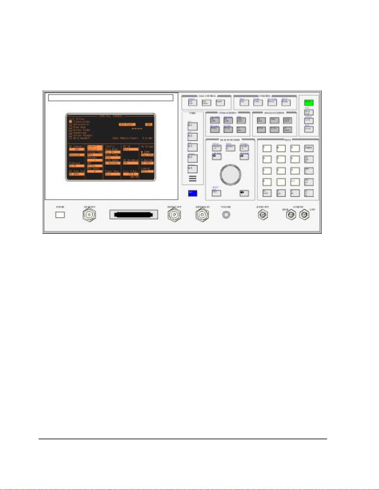
Chapter 1, Description of Keys
Figure 1 Agilent Technologies E8285A Front Panel
30
S:\agilent\e8285\REFGUIDE\MANUAL\keys.chp
Page 31

Keys
Address
Chapter 1, Description of Keys
Keys
Press and release the Shift key, then the Local key to display the GPIB address of
the Test Set. There is no equivalent GPIB command for the Address key
Programming Address
The Test Set’s GPIB address can be changed through GPIB by using the
:CONFigure:BADDress commands. If the Test Set’s GPIB address is changed
programmatically, all future GPIB commands must use the new address.
Example
OUTPUT 714;"CONF:BADD 15"
This sets the Test Set’s GPIB address to 15.
Answer
The Test Set’s GPIB address can be queried through GPIB by using the
:CONFigure:BADDress? commands.
Example
OUTPUT 714;"CONF:BADD?"
ENTER 714;Address
This queries the Test Set’s GPIB address.
See Also
"I/O Configure Screen" on page 119
This key functions only when Answer Mode is set to Manual.
Pressing this key answers CDMA-mode mobile-station-originated ca lls by
removing the ring back tone from the mobile station’s audio path and allowing
user conversation or other traffic to be exchanged.
The Test Set will automatically answer calls if
GPIB Example
“DISP CCNT;CDMA:CALL:ANSW”
Answer Mode is set to Auto.
31
Page 32

Chapter 1, Description of Keys
Keys
Assign
This key is used to assign the User Keys, K1 through K5, and K1’ through K3’.
Press and release the Shift key, then the K4 key to select the Assign function.
No equivalent GPIB command
See Also
“Using USER Keys” in the Operating Overview chapter of the E8285A User’s
Guide
IBASIC User’s Handbook to assign IBASIC commands to user keys
Average
GPIB Example
Press and release the Shift key, then the Increment x10 key to access the average
function. This enables or disables measurement averaging.
Programming Average
The GPIB command :AVERage is used to select this data function
programmatically.
NOTE: Measurement averaging works the same way programmatically as it does manually.
If the Average data function is enabled manually and the number of averages is set to ten
(N=10), the first value displayed is the average of 1 measurement, the second value di splayed
is the average of two measurements, the third value displayed is the average of three
measurements… the tenth value displayed is the average of 10 measurements. For readings
greater than N the data function approximates a hardware single-pole, RC low-pass filter.
If the Average data function is enabled programmatically and the number of averages is set to
ten (N=10) the first value returned through GPI B is the average of 1 measurem ent, the second
value returned through GPIB is the average of two measurements, the third value returned
through GPIB is the average of three measurements…the tenth value returned through GPIB
is the average of 10 measurements. Each successive reading would mimic the output of a
single-pole, RC low-pass filter that had been initially charged to the value of the tenth reading.
If a “true average” value is desired, that is V
procedure through GPIB is to take N sequential readings and calculate the average within the
program context.
= (V1+V2+V3…VN)/N, the recommended
avg
32
S:\agilent\e8285\REFGUIDE\MANUAL\keys.chp
Page 33

Chapter 1, Description of Keys
Keys
To Turn Measurement Averaging ON and OFF. Use the :AVERage:STATe
commands to turn the averag ing data function ON and OFF.
Syntax
:AVERage:STATe ON
:AVERage:STATe OFF
Example
OUTPUT 714;"MEAS:AFR:DISTN:AVER:STAT ON"
This turns the Average data function ON for the AF Analyzer distortion
measurement.
To Query the Measurement Averaging State. Use the :AVERage:STAT?
commands to query the current state of the averaging data function. The returned
value is either: 0 (OFF) or 1 (ON).
Syntax
:AVERage:STAT?
Example
OUTPUT 714;"MEAS:AFR:DISTN:AVER:STAT?"
ENTER 714;State_on_off ! 1 = ON, 0 = OFF
This queries the state of the Average data function for the AF Analyzer
distortion measurement.
To Reset Averaging. Use the :AVERage:RESet commands to restart the
averaging algorithm used to calculate an averaged measurement.
Syntax
:AVERage:RESet
Example
OUTPUT 714;"MEAS:AFR:DISTN:AVER:RES"
This resets the Average Data Function for the AF Analyzer distortion
measurement.
To Set the Number of Averages. Use the :AVERage:VALue commands to set the
number of averages used by the averaging algorithm.
Syntax
:AVERage:VALue
Example
OUTPUT 714;"MEAS:AFR:DISTN:AVER:VAL 25"
This sets the n umber of averages t o 25 for the Av erage data func tion for the AF
Analyzer distortion measurement.
33
Page 34

Chapter 1, Description of Keys
Keys
To Query the Number of Averages. Use the :AVERage:VALue? commands to
query the number of averages used by the averaging algorithm.
This queries the number of averages for the Average data function for the AF Analyzer distortion measurement.
See Also
“To Use Measurement Averaging” in the Operating Overview chapter of the
E8285A User’s Guide.
Syntax
:AVERage:VALue?
Example
OUTPUT 714;"MEAS:AFR:DISTN:AVER:VAL?"
ENTER 714;Num_of_avgs
Call/Page
Cancel
EEX
When this key is pressed, the Test Set attempts a CDMA-mode page to a mobile
station. The Call Status annunciators on the CDMA CALL CONTROL screen
indicate call flow.
Refer to “Set ting Up a Call” chapter in the E8285A Application Guide.
GPIB Example
“DISP CCNT;CDMA:CALL:MAKE”
Cancel is used to cancel an entry in progress, or to stop a running IBASIC
program. For example, if you press Recall to recall an instrument setup, and then
decide not to recall a setting, pressing Cancel exits the recall procedure.
GPIB Example
No equivalent GPIB command
Press and release the Shift key, then the +/- key to access the exponent function.
This function is used for entering numbers using scientific notation.
See Also
“To Enter Values with Exponents” in the Operating Overview chapter of the
E8285A User’s Guide
34
S:\agilent\e8285\REFGUIDE\MANUAL\keys.chp
Page 35

End/Release
Enter
Chapter 1, Description of Keys
Keys
When this key is pressed, the Test Set disconnects any CDMA-mode call that is
currently connected.
GPIB Example
“DISP CCNT;CDMA:CALL:END”
Enter is used to select a field or screen, and to enter numbers when the unit-ofmeasure is not specified. This function is identical to pressing the cursor-control
knob.
GPIB Example
No equivalent GPIB command
Hold
IBASIC reset
Press and release the Shift key, then the Meas reset key. This stops all
measurements. Selecting Hold again resumes measurements.
The Hold key is used to hold/resume all active measurements. There is no
equivalent GPIB command for the Hold key. However, the functionality of the
Hold key can be implemented remotely by using single triggering of
measurements.
GPIB Example
No equivalent GPIB command
See Also
“Measurement Tr iggering Process” in the Operating Overview chapter of the
E8285A User’s Guide
The IBASIC reset key is used to stop an IBASIC program currently running.
35
Page 36

Chapter 1, Description of Keys
Keys
Increment ÷10, Increment set, Increment x10
These keys are used to ch ange the incr ement/decr ement value when changing
field values.
The increment divide-by-10 function reduces the increment setting by a factor
of 10. (New increment setting = current setting
The increment setting function sets the increment value for real-number numeric
entry fields.
The increment multipl y-by-10 funct ion i ncreas es the incr ement se ttin g by a f actor
of 10. (New increment setting = current setting
Programming Increment set
The GPIB command :INCRement is used to select this data function
programmatically.
÷ 10).
× 10).
To Set the Increment Value. Use the :INCRement command to set the increment
value.
Syntax
:INCRement
Example
OUTPUT 714;"RFG:FREQ:INCR 2.5 MHZ"
This sets the increment value for the RF Gen Freq field to 2.5 MHz.
NOTE: When setting the value of a numeric field (such as RF Gen Freq), any non–GPIB unit ’s
unit-of-measure must be specified in the command string, otherwise the current GPIB unit is
assumed by the Test Set. Integer-only fields (such as Intensity and Print Adrs) have
a fixed increment of 1, and they cannot be changed.
To Query the Increment Value.
Use the :INCRement? command to query the
increment value.
Syntax
:INCRement?
Example
OUTPUT 714;"RFG:FREQ:INCR?"
ENTER 714;Incr_value
This queries the increment value for the RF Gen Freq field.
36
S:\agilent\e8285\REFGUIDE\MANUAL\keys.chp
Page 37

Chapter 1, Description of Keys
Keys
NOTE: When querying a field setting or measurement result through GPIB, the Test Set always
returns numeric values in GPIB units or attribute units, regardless of the field’s current display
units setting. Refer to “To Specify Units-of-Measure for GPIB Data Transfer” in the
Operating Overview chapter of the E8285A User’s Guide.
To Set the Increment Mode.
Use the :INCRement:MODE commands to set the
increment mode to linear or logarithmic.
Syntax
:INCRement:MODE <LOGarithm or LINear>
Example
OUTPUT 714;"RFG:FREQ:INCR:MODE LOG"
This sets the increment mode for the RF Generator’ s frequency to logari thmic.
To Query the Increment Mode. Use the :INCRement:MODE? commands to
query the increment mode.
Syntax
:INCRement:MODE?
Example
OUTPUT 714;"RFG:FREQ:INCR:MODE?"
ENTER 714;Mode$ ! returns LIN or LOG
This queries the increment mode of the RF Generator’s frequency.
To Set the Increment Value Display Units. Use the :INCRement:DUNits
commands to set the units-of-measure used to display the increment value. Refer
“To Specify Units-of-Measure for CRT Display” in the Operating Over view chapter
to
E8285A User’s Guide for description of display units.
of the
Syntax
:INCRement:DUNits <disp_units>
Example
OUTPUT 714;"RFG:FREQ:INCR:DUN KHZ"
This sets the increment value’s display units to kHz for the RF Generator’s
frequency.
37
Page 38

Chapter 1, Description of Keys
Keys
NOTE: When querying a field setting through GPIB, the Test Set always returns numeric values in
GPIB units or attribute units, regardless of the field’s current d isplay units setting. Numeric
values are expressed in scientific notation.
Refer to “To Specify Units-of-Measure for GPIB Data Transfer” in the Operating Overview
chapter of the E8285A User’s Guide.
To Query the Increment Value Display Units.
Use the :INCRement:DUNits?
commands to query the units-of-measure used to display the increment value.
Refer to “
chapter of the
To Specify Units-of-Measure for CRT Display” in the Operating Overview
E8285A User’s Guide for description of display units.
Syntax
:INCRement:DUNits?
Example
OUTPUT 714;"RFG:FREQ:INCR:DUN?"
ENTER 714;Disp_unit$
This queries the increment value’s display units for the RF Generator’s
frequency.
Programming Increment÷10
Syntax
:INCRement:DIVide
NOTE: Integer-only fields ( such as Intensity and Print Adrs) have a fixed increment of 1, an d
cannot be changed.
Example
OUTPUT 714;"RFG:FREQ:INCR:DIV"
If the RF Generator’s frequency increment is 10 MHz, this command reduces the
increment value from 10 MHz to 1 MHz.
38
S:\agilent\e8285\REFGUIDE\MANUAL\keys.chp
Page 39

Chapter 1, Description of Keys
Keys
Programming Increment×10
NOTE: Integer-only fields ( such as Intensity and Print Adrs) h ave a fixed increment of 1 , and
cannot be changed.
Syntax
:INCRement:MULTiply
Example
OUTPUT 714;"RFG:FREQ:INCR:MULT"
If the RF Generator’s frequency increment is 1 MHz, this command increases increment value from 1 MH z to 10 MHz.
See Also
K1 - K5, & K1’- K3’
“T o Incr ement/Decremen t Values” in
the Operating Overview chapte r of the E8285A
User’s Guide
These keys are used to dis play f ields fr om anoth er screen , or acc ess f ields wit hout
using the CURSOR CONTROL knob or changing screens.
GPIB Example
No equivalent GPIB command
See Also
“Using USER Keys” in the Operating Overview chapter of the E8285A User’s
Guide
39
Page 40

Chapter 1, Description of Keys
Keys
Local
Local returns the instrument to manual control after GPIB control is used, except
when the T est Set is in local-lock out mode. The Test Set returns to Local operation
(full front-panel control) when either the Go To Local (GTL) bus command is
received, the front-panel Local key is pressed or the REN line goes false. When
the Test Set returns to local mode the output signals and internal settings remain
unchanged, except that triggering is reset to “repetitive” and settling is reset to
“full”. The Local key will not functi on if the Test Set is in the local lockout mode.
Programming Local
Using HP® BASIC, the statement LOCAL returns all specified devices to their
local state.
puts the device at address 14 in local mode.
Example
LOCAL 714
Low limit, High limit
Press and release the Shift key, then the down-arrow key to access the low limit
function. Press and release the Shift key, then the up-arrow key to access the high
limit function. These fu nction s are use d to set measuremen t endpoi nts. Exce eding
the end points causes screen prompts to blink until they are reset.
Programming High Limit and Low limit
The High Limit and Low limit data functions are used to define a measurement
“window” which can be used to detect measured values which are outside the
defined limits. The GPIB commands :HLIMit (high limit) and :LLIMit (low limit)
are used to set these data functions programmatically.
40
S:\agilent\e8285\REFGUIDE\MANUAL\keys.chp
Page 41

Chapter 1, Description of Keys
Keys
To Turn High and Low Measurement Limit Checking ON and OFF. Use the
:HLIMit:STATe and :LLIMit:STATe commands to turn high and low
measurement limit checking ON and OFF.
Syntax
:HLIMit:STATe ON
:HLIMit:STATe OFF
:LLIMit:STATe ON
:LLIMit:STATe OFF
Example
OUTPUT 714;"MEAS:AFR:DISTN:HLIM:STAT ON"
OUTPUT 714;"MEAS:AFR:DISTN:LLIM:STAT ON"
This turns high and low measurement limit checking ON for the AF Analyzer distortion measurement.
To Query the State of High and Low Measurement Limit Checking. Use the
:HLIMit:STATe? and :LLIMit:S TATe? commands to quer y the cu rrent stat e of th e
high and low measurement li mit checking. The returned va lue is either: 0 (OFF)
or 1 (ON).
Syntax
:HLIMit:STATe?
:LLIMit:STATe?
Example
OUTPUT 714;"MEAS:AFR:DISTN:HLIM:STAT?"
ENTER 714;Hi_state ! 1 = ON, 0 = OFF
OUTPUT 714;"MEAS:AFR:DISTN:LLIM:STAT?"
ENTER 714;Lo_state ! 1 = ON, 0 = OFF
This queries the state of high and low measurement limit checking for the AF
Analyzer distortion measurement.
To Set High and Low Measurement Limits. Use the :HLIMit:VALue and
:LLIMit:VALue commands to set the high and low measurement limit values.
Syntax
:HLIMit:VALue
:LLIMit:VALue
Example
OUTPUT 714;"MEAS:AFR:FM:HLIM 7.5 KHZ"
OUTPUT 714;"MEAS:AFR:FM:LLIM 2.5 KHZ"
This sets a high measurement limit of 7.5 kHz and a low measurement limit of
2.5 kHz for the AF Analyzer FM deviation measurement.
NOTE: When setting high and low limit values, a non–Attribute Unit unit-of-measure must be
specified in the command string, otherwise the current Attribute Unit is assumed by the Test
Set. Refer to “To Specify Units-of-Measure for GPIB Data Transfer” in
the Operating
Overview chapter of the E8285A User’s Guide.
41
Page 42

Chapter 1, Description of Keys
Keys
To Set the Display Units for High and Low Measurement Limits. Use the
:HLIMit:DUNits and :LLIMi t:DUNits commands to set th e units-of -measure used
to display the high and low measurement limit values.
Refer to “
To Specify Units-of-Measure for CRT Display” in the Operating Overview
chapter of the E8285A User ’s Guide for description of display units.
Syntax
:HLIMit:DUNits <disp_units>
:LLIMit:DUNits <disp_units>
Example
OUTPUT 714;"MEAS:AFR:FM:HLIM:DUN KHZ"
OUTPUT 714;"MEAS:AFR:FM:LLIM:DUN KHZ"
This sets the high and low measurement limit display units to kHz for the AF
analyzer FM deviation measurement.
NOTE: When querying measurement limits through GPIB, the Test Set always returns numeric values
in attribute units, regardless of the current display units or
GPIB units settings. Numeric values are expressed in scientific notation.
Refer to “To Specify Units-of-Measure for GPIB Data Transfer” in
the Operating Overview
chapter of the E8285A User’s Guide.
To Query the Display Units for High and Low Measurement Limits.
Use the
:HLIMit:DUNits? and :LLIMit:DUNi ts? commands to query the units -of-measure
used to display the high and low measurement limit values.
Refer to “
chapter of the
To Specify Units-of-Measure for CRT Display” in the Operating Overview
E8285A User’s Guide for description of display units.
Syntax
:HLIMit:DUNits?
:LLIMit:DUNits?
Example
OUTPUT 714;"MEAS:AFR:FM:HLIM:DUN?"
ENTER 714;Hi_disp_unit$
OUTPUT 714;"MEAS:AFR:FM:LLIM:DUN?"
ENTER 714;Lo_disp_unit$
This queries the high meas urement limit displ ay units fo r the AF Analyz er FM
deviation measurement.
NOTE: When querying measurement limits through GPIB, the Test Set always returns numeric values
in attribute units, regardless of the current display units or GPIB units settings. Numeric values
are expressed in scientific notation.
Refer to “To Specify Units-of-Measure for GPIB Data Transfer” in
the Operating Overvi ew
chapter of the E8285A User’s Guide.
42
S:\agilent\e8285\REFGUIDE\MANUAL\keys.chp
Page 43

Chapter 1, Description of Keys
Keys
To Query the High and Low Measurement Limit Settings. Use the
:HLIMit:VALue? and :LLIMit:VALue? commands to query the high and low
measuremen t limit settings.
Syntax
:HLIMit:VALue?
:LLIMit:VALue?
Example
OUTPUT 714;"MEAS:AFR:FM:HLIM:VAL?"
ENTER 714;High_limit
OUTPUT 714;"MEAS:AFR:FM:LLIM:VAL?"
ENTER 714;Low_limit
This queries the high and low measurement limits for the AF Analyzer FM
deviation measurement.
NOTE: When querying measurement limits through GPIB, the Test Set always returns numeric values
in attribute units, regardless of the current display units or GPIB units settings. Numeric values
are expressed in scientific notation.
Refer to “To Specify Units-of-Measure for GPIB Data Transfer” in
the Operating Overvi ew
chapter of the E8285A User’s Guide.
To Detect If a Measurement Limit Has Been Exceeded.
Use the
:HLIMit:EX Ceeded? and :LL IMit:EXCeeded? commands to detect if a
measurement limit has been exceeded. The returned value is either: 0 (NO) or 1
(YES).
Syntax
:HLIMit:EXCeeded?
:LLIMit:EXCeeded?
Example
OUTPUT 714;"MEAS:AFR:FM:HLIM:EXC?"
ENTER 714;Hi_limit_exced ! 1= YES, 0 = NO
OUTPUT 714;"MEAS:AFR:FM:LLIM:EXC?"
ENTER 714;Lo_limit_exced ! 1= YES, 0 = NO
This determines if the high or low measurement limits for the AF Analyzer FM deviation measurement have been exceeded.
43
Page 44

Chapter 1, Description of Keys
Keys
To Reset Measurement Limit Detection. Use the :HLIMit:RESet and
:LLIMit:RESet commands to reset measurement limit detection. Once a high or
low measurement limit has been exceeded (:HLIMit:EXCeeded? returns a 1 or
:LLIMit:EXCeeded? returns a 1), measurement limit dete ction is disabled until
reset by the :R ESet command.
This resets high and low measurement limit detection for the AF Analyzer FM deviation measurement.
See Also
Syntax
:HLIMit:RESet
:LLIMit:RESet
Example
OUTPUT 714;"MEAS:AFR:FM:HLIM:RES"
OUTPUT 714;"MEAS:AFR:FM:LLIM:RES"
Meas reset
“Setting Measurement Limits” in the Operating Overview chapter of the E8285A
User’s Guide.
Meas reset clears the measurement history for all of the instrument’s
measurement algori thms ( such as the aver aging and peak hold fu nction s) to r estart
all measurements that are in progress.
Programming Meas reset
The GPIB commands :MEASure:RESet are use d to select this function
programmatically.
Example
OUTPUT 714;":MEAS:RES"
This resets all of the active measurements in the Test Set.
44
S:\agilent\e8285\REFGUIDE\MANUAL\keys.chp
Page 45

Meter
Chapter 1, Description of Keys
Keys
The Meter function displays measurements graphically. The Meter format is
available for most measurements. T o determine if the Meter format is provided for
a measurement, position the cursor in front of the measurement’s units field and
press the knob. If the message “Press ON/OFF, LIMITs, REF, AVG, METER, or
units” is displayed, the meter format is provided.
Programming Meter
The GPIB command :METer is used to select t his data funct ion progr ammatica lly.
To Turn the Meter ON and OFF.
Use the :METer:STATe commands to turn the meter ON and OFF. The parameter
can be a 1 or ON to turn the meter on and a 0 or OFF to turn the meter off.
Syntax
:METer:STATe <ON> or <1>
:METer:STATe <OFF> or <0>
Example
OUTPUT 714;"MEAS:RFR:POW:MET ON"
This turns the analog bar-graph meter ON for the TX power measurement.
45
Page 46

Chapter 1, Description of Keys
Keys
To Query the State of the Meter.
Use the :METer:STATe? commands to query the state of the analog bar-graph
meter. The query returns a 1 if the meter is ON, and a 0 if the meter is OFF.
To Set the Number of Intervals on the Meter.
Use the :METer:INTerval commands to set the number of intervals displayed on
the analog bar-graph meter.
Syntax
:METer:STATe?
Example
OUTPUT 714;"MEAS:RFR:POW:MET:STAT?"
ENTER 714;Meter_on_off ! returns a 1 (ON) or 0 (OFF)
This queries the state of the analog bar-graph meter for the TX power
measurement.
Syntax
:METer:INTerval <integer valve>
Example
OUTPUT 714;"MEAS:RFR:POW:MET:INT 5"
This sets the numbe r of in terva ls displ ayed on the analog b ar-gra ph met er fo r
the TX power measurement.
To Query the Number of Intervals on the Meter.
Use the :METer:INTerval? commands to query the number of intervals displayed
on the analog bar-graph meter.
Syntax
:METer:INTerval?
Example
OUTPUT 714;"MEAS:RFR:POW:MET:INT?"
ENTER 714;Num_intervals
This queries the number of inter vals displ ayed on the analog bar -graph meter
for the TX power measurement.
46
S:\agilent\e8285\REFGUIDE\MANUAL\keys.chp
Page 47

Chapter 1, Description of Keys
To Set the Meter High End and Low End Points.
Use the :METer:HEND and :MEter:LEND commands to set the analog bar-graph
meter’s high endpoint and low endpoint.
Syntax
:METer:HEND <real number>
:METer:LEND <real number>
Example
OUTPUT 714;"MEAS:RFR:POW:MET:HEND 20"
OUTPUT 714;"MEAS:RFR:POW:MET:LEND 10"
This sets the analog bar-graph meter ’s high endp oint to 20 watts and the low
endpoint to 10 watts for the TX power measurement.
NOTE: When setting the value of the Meter data function through GPIB, a
non-Attribute Unit unit-of-measure must be specified in the command string, otherwise the
current Attribute Unit is assumed by the Test Set.
Refer to “To Specify Units-of-Measure for GPIB Data Transfer” in
chapter of the E8285A User’s Guide.
Keys
the Operating Overvi ew
To Query the Meter High End and Low End Points.
Use the :METer:HEND? and :MEter:LEND? commands to query the analog bargraph meter high endpoint and low endpoint.
Syntax
:METer:HEND?
:METer:LEND?
OUTPUT 714;"MEAS:RFR:POW:MET:HEND?"
ENTER 714;Meter_hi_end
OUTPUT 714;"MEAS:RFR:POW:MET:LEND?"
ENTER 714;Meter_lo_end
This queries the high end point and low end point of the analog bar-graph
meter for the TX power measurement.
NOTE: When querying the value of the Meter data f unction thro ugh GPIB, the Tes t Set always r eturns
numeric values in attribute units, regardless of the current display units or GPIB units settings.
Numeric values are expressed in scientific notation.
Refer to “To Specify Units-of-Measure for GPIB Data Transfer” in the Operating Overview
chapter of the E8285A User’s Guide.
47
Page 48

Chapter 1, Description of Keys
Keys
To Set the Meter High End and Low End Point Display Units.
Use the :METer:HEND:DUNits and :MEter:LEND:DUNits commands to set the
analog bar-graph meter high end point and low end point display units. Refer to
To Specify Units-of-Measure for CRT Display” in the Operating Overview chapter of
“
the
E8285A User’s Guide for description of display units.
Syntax
:METer:HEND:DUNits <disp_units>
:METer:LEND:DUNits <disp_units>
Example
OUTPUT 714;"MEAS:RFR:POW:MET:HEND:DUN DBM"
OUTPUT 714;"MEAS:RFR:POW:MET:LEND:DUN DBM"
This sets the high end poi nt and low end point display uni ts of t he analog bargraph meter for the TX power measurement to dBm.
NOTE: When querying the Meter data function through GPI B, the Test Set always returns
numeric values in attribute units, regardless of the current display units or GPIB units
settings. Numeric values are expressed in scientifi c notation.
To Query the Meter High End and Low End Point Display Units.
Use the :METer:HEND:DUNits? and :MEter:LEND:DUNits? commands to
query the analog bar-graph meter high end point and low end point display units.
Refer to “
To Specify Units-of-Measure for CRT Display” in the Operating Overview
chapter of the E8285A User’s Guide for description of display units.
Syntax
:METer:HEND:DUNits?
:METer:LEND:DUNits?
Example
OUTPUT 714;"MEAS:RFR:POW:MET:HEND:DUN?"
ENTER 714;Met_hidisp_unit$
OUTPUT 714;"MEAS:RFR:POW:MET:LEND:DUN?"
ENTER 714;Met_lodisp_unit$
This queries the high end point and low end point display units of the analog
bar-graph meter for the TX power measurement.
NOTE: When querying the Meter data function through GPIB, the Test Set always returns numeric
values in attribute units, regardless of the current display units or GPIB units settings. Numeric
values are expressed in scientific notation.
See Also
“To Use the Analog Meter Format” in the Operating Overview chapter of the
E8285A User’s Guide
48
S:\agilent\e8285\REFGUIDE\MANUAL\keys.chp
Page 49

No Ratio W
On/Off
POWER
Chapter 1, Description of Keys
Keys
No is used to di sre gard selected ope ra ti ons before they a re exe cuted. Press the No
Ratio W key to answer no to prompts requiring a yes or no reply.
GPIB Example
No equivalent GPIB command
See Yes On/Off field description, on page 56.
POWER turns the instrument’s power on and off.
GPIB Example
No equivalent GPIB command
Preset
Previous
Preset restores most of the instrument’s settings to their factory default states,
although most CONFIGURE screen changes are not affected. Instrument selfdiagnostics are not run when Preset is pressed.
Programming Preset
The IEEE 488.2 Common Command *RST is used to select this function
programmatically.
Syntax
*RST
Example
OUTPUT 714;"*RST"
This resets the Test Set to its power-up state.
Previous accesses the previous screen.
GPIB Example
No equivalent GPIB command
49
Page 50

Chapter 1, Description of Keys
Keys
Pressing Print outputs the entire contents of the displayed screen, the time and
date, and any print title defined in the PRINTER CONFIGURE screen. To print
measurement results through GPI B, the pro gram must qu ery the measureme nt and
print the result in a format de termined by the programmer.
No equivalent GPIB command
See Also
"Print Configure Screen" on page 123
“Printing a Screen” in the Operating Overview chapter of the E8285A User’s
Guide
GPIB Example
Recall
Recall is used to recall instrument setups saved in save/recall registers.
Programming Recall
The GPIB commands :REGister:RECall are used to select this function
programmatically. The save/recall mass storage device is selected using the
Save/Recall field on the I/O CONFIGURE screen.
Example
OUTPUT 714;":REG:REC ’SETUP1’"
This recalls the instrument state saved in the file SETUP1.
See Also
“Saving and Recalling Instrument Setups” in the Operating Overview chapter of
the E8285A User’s Guide
“*SAV (Save Instrument State)” in the GPIB Common Commands chapter of the
E8285A Condensed Programming Reference Guide
“*RCL (Recall Instrument State)” in the GPIB Common Commands chapter of
the E8285A Condensed Programming Reference Guide
50
S:\agilent\e8285\REFGUIDE\MANUAL\keys.chp
Page 51

Ref set
Chapter 1, Description of Keys
Keys
Press and release the Shi ft key, then the Increment ÷10 key to access the refere nce
set function. This fu nctio n is us ed to e nte r or r emove a measur ement refe rence for
relative AF and RF measurements.
Programming Ref set
The GPIB command :REFerence is used to select this data function
programmatically.
To Turn Measurement Reference Points ON and OFF. Use the
:REFerence:STATe <boolean> commands to turn measurement reference points
ON and OFF. The <boolean> parameter can be a 1 or ON to turn measurement
reference points on, and a 0 or OFF to turn measurement reference points off.
Syntax
:REFerence:STATe <ON> or <1>
:REFerence:STATe <OFF> or <0>
Example
OUTPUT 714;"MEAS:RFR:POW:REF:STAT ON"
This turns the measurement reference point for the TX power measurement
ON.
To Query the State of Measurement Reference Points. Use the
:REFerence:STATe? commands to query the stat e of a measure ment reference
point. The query returns a 1 if a measurement reference points is ON, and a 0 if a
measurement reference points is OFF.
Syntax
:REFerence:STATe?
Example
OUTPUT 714;"MEAS:RFR:POW:REF:STAT?"
ENTER 714;Meter_on_off ! returns a 1 (ON) or 0 (OFF)
This queries the state of the measurement reference point for the TX power
measurement.
51
Page 52

Chapter 1, Description of Keys
Keys
To Set A Measurement Reference Point. Use the :REFerence:V ALue commands to
set a measurement reference point.
Syntax
:REFerence:VALue <real number>
Example
OUTPUT 714;"MEAS:RFR:POW:REF:VAL 20"
This sets the measurement reference point for the TX power measurement to
20 watts.
NOTE: When setting a measurement reference point, any non–attribute unit’s unit-of-measure must
be specified in the command string, otherwise the current attribute unit is assumed by the Test
Set. Refer to “To Specify Units-of-Measure for GPIB Data Transfer” in
Overview chapter of the E8285A User’s Guide.
the Operating
To Query A Measurement Reference Point.
Use the :REFerence:VALue?
commands to query a measurement reference point.
Syntax
:REFerence:VALue?
Example
OUTPUT 714;"MEAS:RFR:POW:REF:VAL?"
ENTER 714;Ref_val
This queries the measurement referenc e point for th e TX power measuremen t.
NOTE: When querying a measurement reference point through GPIB, the Test Set always returns
numeric values in attribute units, regardless of the current display units or GPIB units settings.
Numeric values are expressed in scientific notation.
Refer to “To Specify Units-of-Measure for GPIB Data Transfer” in
the Operating Overview
chapter of the E8285A User’s Guide.
52
S:\agilent\e8285\REFGUIDE\MANUAL\keys.chp
Page 53

Chapter 1, Description of Keys
To Set Measurement Reference Point Display Units. Use the :REFerence:DUNits
commands to set a measurement reference point’s display units.
Refer to “To Specify Unit s-of-Measure for CRT Display” in th e Operating
Overview chapter of the E8285A User’s Guide for description of display units.
Syntax
:REFerence:DUNits <disp_units>
Example
OUTPUT 714;"MEAS:RFR:POW:REF:DUN DBM"
This sets the measurement reference point’s display units for the TX power
measurement to dBm.
NOTE: When querying a measurement reference point through GPIB, the Test Set always
returns numeric values in Attribute Units, regardless of the current Display Units or
GPIB Units settings. Numeric values are expressed in scientific notation.
Keys
To Query Measurement Reference Point Display Units.
Use the
:REFerence:DUNits? commands to query a measurement reference point’s
Display Units. Refer to “
Operating Overview chapter of the E8285A User’s Guide for description of Display
To Specify Units-of-Measure for CRT Display” in the
Units.
Syntax
:REFerence:DUNits?
Example
OUTPUT 714;"MEAS:RFR:POW:REF:DUN?"
ENTER 714;Disp_unit$
This queries the measurement reference point’s Display Units for the TX
Power measurement.
NOTE: When querying a measurement reference point through GPIB, the Test Set always returns
numeric values in Attribute U nits, regardless of the current D isplay Units or GPIB Units
settings. Numeric values are expressed in scientific notation.
See Also
“To Set a Measurement Reference” in the Operating Over view chapter of the
E8285A User’s Guide.
53
Page 54

Chapter 1, Description of Keys
Keys
Register
This key causes the mobile station to perform a CDMA zone-based registration.
See
Release
This key is used to delete the assignment of the User Keys, K1 through K5, and
K1’ through K3’. Press and release the Shift key, then the K5 key to select the
Release function.
No equivalent GPIB command
See Also
"Register (CDMA)" on page 358.
GPIB Example
Save
“Using USER Keys” in the Operating Overview chapter of the E8285A
User’s Guide
IBASIC User’s Handbook to assign IBASIC commands to User Keys
Press and release the Shift key, then the Recall key to access the save function.
This stores instrument setups.
Programming Save
The GPIB commands :REGister:SAVE are us ed to select this function
programmatically. The save recall mass storage device is selected using the
Save/Recall field on the I/O CONFIGURE screen.
Example
OUTPUT 714;"REG:SAVE ’SETUP1’"
This saves the instrument state to a file named SETUP1:
Removing Saved Instrument St ates. One or all of the saved instrument states can
be removed from the selected save/recall mass storage device. The
save/recall mass storage device is selected using the
Save/Recall field on the
I/O CONFIGURE screen. The GPIB commands :REGister:CLEar are used to
perform this function programmatically.
54
S:\agilent\e8285\REFGUIDE\MANUAL\keys.chp
Page 55

Chapter 1, Description of Keys
Keys
NOTE: The :REGister:CLEar:ALL command is only valid for the internal save/recall mass storage
device. To clear all saved instrument states from the Card, RAM, or Disk save/recall mass
storage devices, each file must be removed individually using the :REGister:CLEar ’<file
name>’ command.
Example
OUTPUT 714;"REG:CLE ’SETUP2’"
This clears the instrument state SETUP2 from the selected save/recall mass
storage device.
Example
OUTPUT 714;"REG:CLE:ALL"
This clears all saved instrument states from the internal save/recall mass storage
device.
See Also
“Saving and Recalling Instrument Setups” in the Operating Overview chapter of
the E8285A User’s Guide
Shift
“Measurement Tr iggering Process” in the Operating Overview chapter of the
E8285A User’s Guide
“*SAV (Save Instrument State)” in the GPIB Common Commands chapter of the
E8285A Condensed Programming Reference Guide
“*RCL (Recall Instrument State)” in the GPIB Common Commands chapter of
the E8285A Condensed Programming Refe rence Guide
Shift is used to sele cted the blue- labeled funct ions listed above some keys (suc h as
Printer, Config, Release, EEX, and so forth).
GPIB Example
No equivalent GPIB command
55
Page 56

Chapter 1, Description of Keys
Keys
Yes On/Off
Yes is used to confirm selected opera ti ons befo re they are executed. Press the Yes
On/Off key to answer yes to prompts requiring a yes or no reply.
On/Off is used to enable and disable measurements, and to turn numeric fields
(such as
No equivalent GPIB command
See Also
“Using the On/Off Functions” in the Operating Overview chapter of the E8285A
User’s Guide
Amplitude) on and off.
GPIB Example
0 to 9, decimal point (.), +/-, and A to F
These keys are for entering and changing values. A through F are shifted
functions. Pres s and re lease t he Sh ift key, then the appro priate key ( 0 through 5) to
select the letter A through F.
See Also
“To Enter and Change Values” in the Operating Overview chapter of the E8285A
User’s Guide
56
S:\agilent\e8285\REFGUIDE\MANUAL\keys.chp
Page 57

Symbol Keys
Backspace
The backspace key is used to move the cur sor to t he left when entering numbers i n
a field, such as
to the left, erasing the previous character.
No equivalent GPIB command
Down-Arrow, Up-Arrow
These keys increment (up-arrow) or decrement (down-arrow) field values. The
increment value is determined by the Increment set (:INCRement) data
function.These keys are also used to select alternate field entries without
displaying the
the cursor in string ent ry fiel ds (such as the
CONFIGURE screen).
Chapter 1, Description of Keys
Symbol Keys
RF Gen Freq. Each press of this key moves the cursor one place
GPIB Example
Choices menu used by some fields. They are also used to move
Print Title field on the PRINTER
Programming Increment Up/Down (Arrow Keys)
Syntax
:INCRement <UP or DOWN>
Example
OUTPUT 714;"RFG:FREQ:INCR UP"
This increases the RF Generator’s frequency by one increment value.
See Also
“T o Incr ement/Decremen t Values” in
the Operat ing Overview chapter of the
E8285A User’s Guide
57
Page 58

Chapter 1, Description of Keys
Symbol Keys
Units-of-Measure Keys
The units keys are fo r enterin g and changin g the uni t-of-mea sure (such as GHz, V,
dBm, %, mW, and so forth) for measurements or field entries. Milliwatts (mW) is
a shifted function. Press and release the Shift key, then the HzmW .
See Also
“T o Sp ecify Units- of-M easure ” in t he Opera ting Overvi ew chapt er of the E828 5A
User’s Guide
µV-ms key to select
58
S:\agilent\e8285\REFGUIDE\MANUAL\keys.chp
Page 59

Miscellaneous Hardware
Front Panel Knobs
Cursor Control Knob
The large knob on the Test Set’s front panel has three functions:
• Moving the cursor.
• Selecting fields, screens, and settings from a list of choices .
• Changing numeric field values.
VOLUME
The VOLUME knob controls the speaker volume for monitoring the AF Analyzer's
selected input. The volume is also affected by the Speaker Vol and Speaker ALC
fields in the analog AF ANALYZER screen.
Chapter 1, Description of Keys
Miscellaneous Hardware
59
Page 60

Chapter 1, Description of Keys
Programmable Front-Panel Keys for Screens
Programmable Front-Panel Keys for Screens
Table 2
Key Name Screen Displayed GPIB Example
AF analyzer AF ANALYZER
“DISP AFAN”
Authentication CDMA AUTHENTICATION “DISP CAUT”
Call control (CDMA) CDMA CALL CONTROL
Call control (ANALOG) CALL CONTROL
Cell config CDMA CELL SITE CONFIGURATION
“DISP CCNT”
“DISP ACNT”
“DISP CCON”
Config CONFIGURE “DISP CONF”
Duplex DUPLEX TEST
Gen control CDMA GENERATOR CONTROL
MS report CDMA MOBILE REPORTED PILOT STRENGTH
“DISP DUPL”
“DISP CGEN”
“DISP CMOB”
MS FER CDMA MOBILE REPORTED FER “DISP CFER”
Printer PRINTER CONFIGURE “DISP PCON”
RX test (CDMA) CDMA CELLULAR MOBILE RECEIVER TEST
RX test (ANALOG) RX TEST
Spectrum CDMA REVSERSE CHANNEL SPECTRUM
Spectrum analyzer SPECTRUM ANALYZER
“DISP CTXR”
“DISP RX”
“DISP CSP”
“DISP SAN”
SMS CDMA SHORT MESSAGE SERVICE
TX range CDMA TRANSMITTER POWER RANGE TEST
TX test (CDMA) CDMA CELLULAR MOBILE TRANSMITTER TEST
TX test (ANALOG) TX TEST
60
S:\agilent\e8285\REFGUIDE\MANUAL\keys.chp
“DISP CSMS”
“DISP CTXR”
“DISP CTXT”
“DISP TX”
Page 61

Non-Programmable Front-Panel Keys and Functions
Non-Programmable Front-Panel Keys and Functions
ON/OFF Power Switch
VOLUME Control Knob
Cursor Control Knob
Shift Key
Cancel Key
Yes On/Off Key
No Ratio W Key
Enter Key
Backspace (left-arrow) Key
Previous Key
Hold Key
Help Key
Print Key
Address Key
K1, K2, K3, K4, K5, K1’, K2’, K3’, Assign, Release (USER Keys)
Chapter 1, Description of Keys
61
Page 62

Chapter 1, Description of Keys
DATA FUNCTIONS Keys
DATA FUNCTIONS Keys
The DAT A FUNCTIONS keys can be di vided i nto two groups; th ose whic h af fec t
measurements (Ref set, Meter, Average, High limit and Low limit), and those
which affect numeric entry fields (Increment
up-arrow, down-arrow). For measurements, the data functions enable the
programmer to change the way measurements are calculated and displayed, and
provide measurement limit detection. For numeric entry fields, the data functions
enable the programmer to set, scale, and change the field’s increment value.
Refer to the “Number Measurement Syntax” in the GPIB Command Syntax
chapter of the E8285A Condensed Programming Reference Guide for full
command syntax.
÷10, Increment set, Increment×10,
Guidelines for Using Measurement Data Functions
• Data functions are turned ON and OFF for individual measurements. The GPIB Data
Function commands must immediately follow the GPIB command for the individual
measurement. For example, to turn the Average data fun ction ON f or the AF Analyzer
distortion measurement, the followin g co mmand string would be sent to the Test Set:
OUTPUT 714;"MEAS:AFR:DISTN:AVER:STAT ON"
• Attribute Units (AUNits) are used with the data functions to specify the units-ofmeasure for numeric data which is read or set through GPIB.
Refer to “To Specify Units-of-Measure for GPIB Data Transfer” in
Overview
• Data function settings, such as number of averages or reference value, are retained if
the function is turned off. The setting values are initiali zed or changed under the
following conditions:
• The Test Set is turned off.
• The Test Set is preset.
• A saved register is recalled.
chapter of the E8285A User’s Guide.
the Operating
62
S:\agilent\e8285\REFGUIDE\MANUAL\keys.chp
Page 63

Guidelines for Using Numeric Entry Field Data Functions
• Increment values are set, scaled, and changed for individual numeric entry fields. The
GPIB data function commands must immediately follow the GPIB command for the
individual field. For example, to set the incr ement value for the RF Generator frequency
to 2.5 MHZ, the following command string would be sent to the Test Set:
OUTPUT 714;"RFG:FREQ:INCR 2.5 MHZ"
• GPIB Units (UNITs) are used with the data functions to specify the units-of-measure
for numeric data which is read or set through GPIB.
Refer to “To Specify Units-of-Measure for GPIB Data Transfer” in
Overview
• Data function settings are not retained. The setting values are initialized or changed
under the following cond itions:
• The Test Set is turned off (values initialized on power up).
• The Test Set is preset (values initialized).
• A saved register is recalled (values changed to those in the recalled register).
chapter of the E8285A User’s Guide.
Chapter 1, Description of Keys
DATA FUNCTIONS Keys
the Operating
63
Page 64

Chapter 1, Description of Keys
USER Keys
USER Keys
User keys instantly access instrument settings without using the knob. You can
use user keys to move quickly between fields on the same screen, and to access
field settings that are not normally available on the screen you are using.
Local user keys ar e u sed to move between settings on the screen that i s d is p la yed.
When the user key is pressed, the cursor instantly moves to, and selects, the
assigned field; eliminating the need to turn and push the knob. Five local user
keys are available for each screen: K1, K2, K3, K4, and K5.
Five factory-as si gned local user ke ys a re available in eac h s cr een; however, using
these keys removes any other local user keys you may have already set up.
Global user keys are used to access settings that are not available on the current
screen. Three global user keys are available: K1’, K2’, and K3’. (These are shifted
functions of the local user keys.)
When defining user keys, th e Ass ign fu nctio n is us ed t o crea te key defin it ions; the
Release function removes the definitions. Re-assigning a user key to a different
field setting au tomatically releases it from the s et ti ng it was previously associated
with.
64
S:\agilent\e8285\REFGUIDE\MANUAL\keys.chp
Page 65

2
Description of Connectors
The connectors are listed in alphabetical order.
65
Page 66

Chapter 2, Description of Connectors
CALL CONTROL UTILITIES
Answer Print Printer I/O config Help
Call/
End/
Page
USER
K1'
K1
K2'
K2
K3'
K3
Assign
K4
Release
K5
Register Tests Config Previous Message
Release
CDMA SCREENS
Cell config Spectrum SMS
Call
Gen
control
MS report MS FER
RX test
Ref set
Increment
10
Low limit
Authen-
control
tication
TX test
TX
range
DATA FUNCTIONS DATA
Meter
Average
Increment
Increment
set
x 10
High limit
ANALOG SCREENS
Call
Duplex Spectrun
control
RX test TX test AF
7 8 9
4 5 6
1 2 3
0 . +/-
IBASIC
Shift
reset
Cancel
Yes
On/Off
No
Ratio
W
analyzer
analyzer
%dBHz
Preset
Hold
Meas
reset
Address
Local
Save
Recall
Enter
Ghz
dBm
dB
MHz
V
%
kHz
mV
s
mW
µV
ms
DUPLEX OUTRF IN/OUTPOWER ANTENNA IN VOLUME AUDIO OUT AUDIO IN
DO NOT apply RF
when in standby
Max power 2.5W
Max power 60 mW Max 12V peak Max
Figure 2 Agilent Technologies E8285A Front Panel
MODULATION
INPUT
COMPOSITE
VIDEO
AUD MONITOR
OUTPUT
CELLSITE/TRIGGERS PARALLEL PORT
PROTOCOL SERIAL
EXT REF
INPUT
TRAFFIC CHANNEL
LOGGING (DCS1)
PAGING CHANNEL
LOGGING (DCS2)
10 MHz
OUTPUT
16X CHIP
OUTPUT
CDMA CLOCK
MUX OUTPUT
SERIAL PORT 9
SERIAL PORT 10
HP-IB
EVEN SEC
INPUT
SA TRIG
OUTPUT
High
Low
42V peak
Figure 3 Agilent Technologies E8285A Rear Panel
66
S:\agilent\e8285\REFGUIDE\MANUAL\connectr.chp
8285bck.eps
Page 67

Connectors
ANTENNA IN
Chapter 2, Description of Connectors
Connectors
The antenna input is used to analyze low-power RF signals (≤ 200 mW), and is
typically used for off-the-air measurements. This port can be selected in the
CONFIGURE, CDMA REVERSE CHANNEL SPECTRUM, analog TX TEST,
DUPLEX TEST, RF ANALYZER, or SPECTRUM ANALYZER screens.
Operating Considerations
•BNC
• Input impedance = 50
• TX Power cannot be measured using this port; use the RF IN/OUT port. However, low
power levels can be measured using this port with the spectrum analyzer.
• Additional sensitivity for this port is available using the Sensitivity field in the
analog RF ANALYZER and SPECTRUM ANALYZER screens.
Ω
CAUTION: Connecting a signal of >200 mW to the ANT IN port can cause instrument damage (although
internal protection circuits can typically withstand a short-duration signal of 1 or 2 Watts).
If the over-power circuit is triggered (signified by a warning message at the top of the screen),
remove the signal from the ANT IN port, and press the
Meas reset key, or turn the Test Set off and on to reset it.
67
Page 68

Chapter 2, Description of Connectors
Connectors
AUDIO IN LOW, HIGH
The audio inputs are used to input audio signals to the AF Analyzer.
• AUDIO IN HI is the main audio signal input connection.
• AUDIO IN LO is used for the audio signal reference. Three choices are available using
the AF ANALYZER screen's Audio In Lo field:
• Gnd - connects the center pin through approximately 100Ω to chassis ground
• Float - provides a floating input.
• 600 T o Hi - provides a 60 0 ohm intern al load to match an au dio source with an o ut-
put.
The measured level is t he po tential between the HIGH an d LOW cent er pi ns. The
shells of both connectors are at chassis ground.
Operating Considerations
•BNC
• Input impedance switchable between
•1 MΩ in parallel with 95 pF,
•600Ω floating.
• This port is selected as the AF Analyzer's input using the AF Anl In field in the
analog TX TEST screen, DUPLEX TEST screen, and AF ANALYZER screen. This
port is always the AF Analyzer's input when the analog RX TEST screen is displayed.
• Signals input to the AF Analyzer are routed through different filters, amplifiers, and
detectors that affect the displayed measurement.
CAUTION: The maximu m level bet ween the HI an d LO center pins i s 42 V peak (app roximat ely 30 Vrms).
Exceeding this value can cause permanent instrument damage.
See Also
AF Anl In
Audio In Lo
68
S:\agilent\e8285\REFGUIDE\MANUAL\connectr.chp
field description, on page 155
field description, on page 169
Page 69

AUDIO OUT
The audio output is used to output signals from AF Generators 1 and 2.
Operating Considerations
•BNC
• Output impedance <1
• Maximum output current = 20 mA peak
• Maximum reverse voltage = 12 V peak
• The output level is set by the AF Generators, and it is not affected by the front-panel
VOLUME control.
• AC/DC coupling is s elect ed us i ng th e Audio Out field. This field is available in the
DUPLEX TEST screen, RF GENERATOR screen.
AUD MONITOR OUTPUT
The audio monitor output provides an external output from various tap points in
the AF Analyzer path.
Chapter 2, Description of Connectors
Connectors
Ω
Operating Considerations
•BNC
• Output impedance is < 1 k
•The Scope To field on the analog AF ANALYZER screen determines the source of
this signal.
• The level is not affected by the front-panel VOLUME knob.
See Also
Scope To
field description, on page 379
Ω
69
Page 70

Chapter 2, Description of Connectors
Connectors
CELL SITE/TRIGGERS
This is a DB-25 connector. It provides various CDMA triggers and digital cell
diagnostics.
Operating Considerations
• Pins 1, 2, 3 Ground
• Pin 4 - Closed Loop Power Control Ramp Down (CSD1_TRIG1)
TTL, 1.8 µs positive pulse indicating ramp down beginning.
NOTE: This trigger does not align exactly with the outgoing power control bit in the RF signal. It
occurs about 72 microseconds before the next 1.25 ms clock edge.
• Pin 5 - Reserved (AMB_TRIG_OUT)
• Pin 6 - Ground
• Pin 7 - DSP TRIG IN, TTL
• Pin 8 - Reserved (HDSET_TX+)
• Pin 9 - Reserved (HDSET_RX+)
• Pin 10 - Ground
• Pin 11 - Reserved (AMB_PDC_DATA_IN
• Pins 12, 13 - No connect
• Pin 14 - Baseband I modulation signal (I_MOD_DRIVE)
120 mVrms, nominal into 50 ohms.
• Pin 15 - Baseband Q modulation signal (Q_MOD_DRIVE)
120 mVrms, nominal into 50 ohms.
• Pin 16 - Closed Loop Power Control Ramp Up (CSD1_TRIG0)
TTL, 1.8 µs positive pulse indicating ramp up beginning.
NOTE: This trigger does not align exactly with the outgoing power control bit in the RF signal. It
occurs about 72 microseconds from the next 1.25 ms clock edge.
• Pin 17 - Reserved (CSD1_TRIG2)
TTL
• Pin 18 - Reserved (DSP2_TRIG_OUT)
• Pin 19 - External scope trigger input (EXT_TRIG_IN)
TTL
• Pin 20 - Ground
• Pin 21 - Reserved
• Pin 22 - Reserved
• Pin 23 - Reserved
• Pin 24 - Ground
• Pin 25 - No Connect
70
S:\agilent\e8285\REFGUIDE\MANUAL\connectr.chp
Page 71

CDMA CLOCK MUX OUTPUT
The CDMA frame clocks provide the CDMA timing re ferences for generating and
demodulating CDMA signals. The CDMA clock MUX output provides the
following CDMA frame clocks on a multiplexed output.
1.25 ms
20.00 ms
26.67 ms
80.00 ms
2.00 s
Each of these CDMA frame clocks is available by selecting from the list of
choices displayed on the CONFIGURE screen.
Operating Considerations
•BNC
• Select which frame clock will be output on the CDMA CLOCK MUX OUTPUT
connector by pressing the Config to select the CONFIGURE screen, then selecting the
Frame Clock field to display the list of choices.
• Nominal output level is >+5 dBm
• Output impedance is 50
• All frame clocks are locked to the Test Set’s timebase, internal or external. Refer to the
TimeBase field on the CONFIGURE screen.
Chapter 2, Description of Connectors
Connectors
Ω
See Also
Frame Clock
EVEN SEC INPUT
COMPOSITE VIDEO
The composite video o utput p rovide s a si gnal f or usi ng an ext ernal vi deo monitor.
The signal provides a duplicate of the Test Set’s screen.
Operating Considerations
•BNC
• A multi-sync monitor must be used to match the video sync rate of 19.2 kHz. Example
field description, on page 263
field description, on page 72
monitors include - Electrohome EC M 1410-DMS 14 -inch co lor monit or and the EVM
1242-P4VID 12-inch monochrome monitor.
71
Page 72

Chapter 2, Description of Connectors
Connectors
DUPLEX OUT
The duplex output is an output for the RF Generator and Tracking Generator.
Operating Considerations
•Type N
• Output impedance = 60
• The RF Generator's output is selected in the Output Port field. This field is
available on the CONFIGURE, CDMA REVERSE CHANNEL SPECTRUM, analog
RX TEST, DUPLEX TEST, RF GENERATOR, and SPECTRUM ANALYZER
screens.
CAUTION: Connecting an RF source of >200 mW to this connector can permanently damage the
instrument.
Ω
EVEN SEC INPUT
This input allows the user to synchronize t he Test Set’s CDMA frame clocks with
an external trigger. The input must be a positive edge TTL signal, and must be
present when the Test Set is turned on.
Operating Considerations
The input must be a positive edge TTL signal. When the Test Set is powered on,
s
µ
the frame clocks will align to within 2.4 and 3.25
See Also
CDMA CLOCK MUX OUTPUT
field description, on page 71
after the trigger.
72
S:\agilent\e8285\REFGUIDE\MANUAL\connectr.chp
Page 73

EXT REF INPUT
Chapter 2, Description of Connectors
Connectors
This input provides a fr eq uency reference for th e Test Set’s internal phase- loc ked loops.
Operating Considerations
•BNC
• This Test Set does not require a jumper between the 10 MHz OUTPUT and the EXT
REF INPUT.
• When the TimeBase field is set to Auto
reference signal once it has been detected on the rear-panel EXT REF INPUT
connector. Below the TimeBase field the Test Set will display External if an
external reference signal is detected. If not, the Test Set will display Internal,
indicating that the Test Set is using its internal high-stability 10 MHz timebase as a
reference.
• When the TimeBase field is set to Int
Internal, and the Test Set will use its internal high-stability 10 MHz timebase as a
reference.
• Input level m ust be >0.15 Vrm s
• Input impedance = 50 ohms
• Duty cycle must be 90%
, the Test Set will lock to a 1, 2, 5, or 10 MHz
, the TimeBase field will display
GPIB
The main GPIB port allows communication between the Test Set and other
instruments or computers using the General Purpose Interface Bus (GPIB).
Operating Considerations
• 36-pin GPIB
See Also
GPIB Adrs
field description, on page 272
73
Page 74

Chapter 2, Description of Connectors
Connectors
MODULATION INPUT
This connector provides an external modulation connection to the RF Generator.
Operating Considerations
Input impedance = 600Ω
Maximum input level = 12 V peak
Full scale input = 1 V peak
Mod In To field of the RF GENERATOR screen sets the type of modulat ion
The
(AM or FM) and sensitivity (%AM/Vpk or kHz/Vpk) for this connection.
FM Coupling field in the RF GENERATOR, DUPLEX TEST, and various
The
encoder modes selects ac or dc coupling of this signal for FM operation.
PAGING CHANNEL LOGGING (DCS2>)
The Paging Channel Logging port provides for logging protocol signaling from
the Paging channel. Refer to Protocol Logging in the Application Guide.
Operating Considerations
• 9-pin sub-miniature D
• 115.2k Baud
•8 bit
• No parity
• No flow control
Pin assignments for this connector are as follows::
Pin 1 - Not Used
Pin 2 - RX_A, RS-232
Pin 3 - TX_A, RS-232
Pin 4 - Not Used
Pin 5 - Ground
Pin 6 - Not Used
Pin 7 - Reserved
Pin 8 - Reserved
Pin 9 - Not Used
74
S:\agilent\e8285\REFGUIDE\MANUAL\connectr.chp
Page 75

PARALLEL PORT
Chapter 2, Description of Connectors
Connectors
This port is u sed with printers requiring a parallel interface when printing screen
images or test results. Set the
CONFIGURE screen or TESTS (Printer Setup) screen) to
Printer Port: field (on the PRINT
Parallel to print
using this port. Use address 15 when sending data to this port from IBASIC
programs.
Operating Considerations
• 25-pin Centr onics
Pin assignments for this connector are as follows:
Pin 1 - nStrobe
Pin 2 - Data 1 (Least Significant Bit)
Pin 3 - Data 2
Pin 4 - Data 3
Pin 5- Data 4
Pin 6 - Data 5
Pin 7- Data 6
Pin 8 - Data 7
Pin 9 - Data 8 (Most Significant Bit)
Pin 10 - nAck
Pin 11 - Busy
Pin 12 - PError
Pin 13 - Select
Pin 14 - nAutoFd
Pin 15 - nFault
Pin 16 - nInit
Pin 17 - nSelectIn
Pin 18 - Signal Ground (nStrobe)
Pin 19 - Signal Ground (Data 1 and Data 2)
Pin 20 - Signal Ground (Data 3 and Data 4)
Pin 21 - Signal Ground (Data 5 and Data 6)
Pin 22 - Signal Ground (Data 7 and Data 8)
Pin 23 - Signal Ground (Busy and nFault)
Pin 24 - Signal Ground (PError, Select, and nAck)
Pin 25 - Signal Ground (nAutoFd, nSelectIn, and nInit)
PROTOCOL SERIAL
This connector provides access to Test Set diagnostics and is intended to be used
only by factory service representatives.
75
Page 76

Chapter 2, Description of Connectors
Connectors
RF IN/OUT
The RF IN/OUT port allows full-duplex interaction, or the RF IN portion can be
used with the DUPLEX OUT port, which provides increased output power.
Operating Considerations
When testing CDMA mobile stations, it is important to enter an RF Level Offset
for the selected input and output ports. Refer to “Calibrating the Test Set” chapter
in the Agilent Technologies E8285A Application Guide.
•Type-N
• This port must be used when measuring transmitter (RF) power.
• This port can be selected in the CONFIGURE, CDMA REVERSE CHANNEL
SPECTRUM, analog TX TEST, DUPLEX TEST, R F ANALYZER, or SPECTRUM
ANALYZER screens.
• Signals ≤ 60 mW can be input to the ANT IN connector for all RF measurements except
transmitter power.
Over-Power Damage. Refer to the Test Set's front panel for maximum input power level.
Exceeding this level can cause permanent instrument damage.
CAUTION: If the RF power at the RF IN/OUT po rt exceed s allowable limits, a loud warning signal sou nds
and a message appears at the top of the screen.
If this occurs, disconnect the RF power, press the Meas reset key, and allow the Test Set to cool
off for approximately 2 minutes before making any other measurements on this port.
SA TRIG OUTPUT
This connector provides a trigger signal for measuring a mobile station’s time
response to open loop power control using an external spectrum analyzer.
Test Sets with firmware revisions A.04.50 and higher include a measurement that
automatically triggers a power versus time measurement at the correct time
relative to the Test Set’s output level change and displays a graph showing the
mobile station’s time response to open loop power control. See "Measuring Time
Response of Open Loop Power Control" in chapter 5 in the Application Guide.
Operating Considerations
•BNC
• Trigger occurs 180 microseconds before the RF power changes
• Trigger rise time is negligible (approximately 600 ns).
76
S:\agilent\e8285\REFGUIDE\MANUAL\connectr.chp
Page 77

Chapter 2, Description of Connectors
Connectors
SERIAL PORT 9
This connector is the primary serial port (SERIAL PORT 10 is the secondary),
and is used for serial data exchange with an external device. Applications might
include printing test r esult s to a ser ia l prin ter, controlling a mobile station thro ugh
a proprietary serial bus, entering IBASIC programs, or sending test results from
the IBASIC controller to a connected controller, disk drive, or terminal.
NOTE: If you are attempting to connect a serial printer using an R J-11 connector, you will need an
adapter to connect to this 9-pin sub-miniature D connector. The adapter is available through
Black Box© Corporation. Order item DB9RJ-11, code number FA067.
Operating Considerations
• You must select Port 9 in the Serial Port field on the I/O CONFIGURE screen to
define serial communication settings for SERIAL PORT 9.
• Use SERIAL PORT 9 for connecting the test set to a serial printer. Do not use SERIAL
PORT 10.
• The IBASIC controller sends and receives data to SERIAL PORT 9 using address 9.
• 9-pin sub-miniature D
Pin assignments for this connector are as follows::
Pin 1 - DCD, RS-232
Pin 2 - RX, RS-232
Pin 3 - TX, RS-232
Pin 4 - DTR, RS-232
Pin 5 - Ground
Pin 6 - DSR, RS-232
Pin 7 - RTS, RS-232
Pin 8 - CTS, RS-232
Pin 9 - RI, RS-232
77
Page 78

Chapter 2, Description of Connectors
Connectors
SERIAL PORT 10
This connector is a secondary serial por t (SERIAL PORT 9 is the primary), and is
used for serial data exchange with an external device. Applications might include
controlling a mobile station through a proprietary serial bus, entering IBASIC
programs, or sending test results from the IBASIC controller to a connected
controller, disk drive, or terminal.
Operating Considerations
• You must select Port 10 in the Serial Port field on the I/O CONFIGURE screen to
define serial communication settings for SERIAL PORT 10.
• Do not use SERIAL PORT 10 for connecting the test set to a serial printer. Use
SERIAL PORT 9.
• The IBASIC controller sends and receives data to SERIAL PORT 10 using address 10.
• 9-pin sub-miniature D
Pin assignments for this connector are as follows::
Pin 1 - DCD, RS-232
Pin 2 - RX, RS-232
Pin 3 - TX, RS-232
Pin 4 - DTR, RS-232
Pin 5 - Ground
Pin 6 - DSR, RS-232
Pin 7 - RTS, RS-232
Pin 8 - CTS, RS-232
Pin 9 - RI, RS-232
78
S:\agilent\e8285\REFGUIDE\MANUAL\connectr.chp
Page 79

TRAFFIC CHANNEL LOGGING (DCS1>)
The Traffic Channel Logging port provides for logging protocol signaling from
the Traffic channel. Refer to Protocol Logging in the Application Guide.
Operating Considerations
• 9-pin sub-miniature D
• 115.2k Baud
•8 bit
• No parity
• No flow control
Pin assignments for this connector are as follows::
Pin 1 - Not Used
Pin 2 - RX_A, RS-232
Pin 3 - TX_A, RS-232
Pin 4 - Not Used
Pin 5 - Ground
Pin 6 - Not Used
Pin 7 - Reserved
Pin 8 - Reserved
Pin 9 - Not Used
Chapter 2, Description of Connectors
Connectors
16X CHIP OUTPUT
The 16X CHIP OUTPUT is a 19.6608 MHz clock output synchronized with the
1.2288 MHz chip rate that sprea ds the CDMA si gnal. The 16X CHIP OUTPUT is
phase-locked to the Test Set’s internal 10 MHz reference.
Operating Considerations
•BNC
• Nominal output level is >+5 dBm
• Output impedance is 50
• All frame clocks are locked to the Test Set’s internal 10 MHz reference frequency
stability is the same as the signal applied to the REF INP UT connector.
See Also
"CELL SITE/TRIGGERS" on page 70
Ω
79
Page 80

Chapter 2, Description of Connectors
Connectors
10 MHz OUTPUT
The 10 MHz output is one output of a reference phase-locked-loop that generates
10 MHz reference signals for all of the digital and analog phase-locked-loops in
the Test Set. This reference phase-locked-loop can lock to many frequencies,
which are listed in the description of the EXT REF INPUT connector.
Operating Considerations
•BNC
• This reference signal will be phase-locked to the reference input if the operating
conditions specified in the EXT REF INPUT connector d escription are met.
• Nominal output level is >+5 dBm
• Output impedance is 50
• Frequency stability is the same as the signal applied to the EXT REF INPUT connector.
See Also
Ω
"EXT REF INPUT" on page 73
80
S:\agilent\e8285\REFGUIDE\MANUAL\connectr.chp
Page 81

3
Description of Screens
These screens are listed in alphabetical order.
81
Page 82

Chapter 3, Description of Scre ens
Adjacent Channel Power Screen
Adjacent Channel Power Screen
Figure 4 The Adjacent Channel Power Screen
This screen is used to meas ure Adjacen t Channel Power. This is a measurement of
the power of signals at a specific channel spacing above and below the RF
Analyzer’s center frequency. This screen is accessed by selecting
from the
Analog To Screen menu.
AD CH PWR
82
S:\agilent\e8285\REFGUIDE\MANUAL\screens.chp
Page 83

Chapter 3, Description of Screens
Adjacent Channel Power Screen
How the Test Set Measures Adjacent Channel Power (ACP)
When you access this s creen, the Test Set automatically st arts a multi-step pr ocess
for measuring ACP:
1. AF Generator 1 is turned off if the Carrier Ref field is set to Unmod.
2. The amplitude of the center frequency (Tune Freq) is measured to establish a refer-
ence.
3. AF Generator 1 is turned back on if it was previously turned off.
4. The power in each of the adjacent channels is analyzed.
5. Adjacent Channel Power is calculated and displayed. This value can be displayed as an
absolute power level or as a ratio referenced to the center frequency’s level.
NOTE: Which Input Port to Use. The TX Power measurement is used to calculate absolute Adjacent
Channel Power. Since TX Power can only be measured using the RF IN/OUT port, you must
use this port to measure ACP Level. ACP Ratio can be measured using either the RF IN/OUT
or the ANT IN port.
Measuring ACP on AM Transmitters. When measuring AM signals, the reference level
must be measured on an unmodulated carrier; so the Carrier Ref field must be set to
Unmod. After the reference is measured, the power in the adjacent channels must be measured
with modulation. This requires the modulating signal to be turned off and on repeatedly as
measurements are being calculated and displayed. Since the Test Set automatically turns
AFGen1 on and off when the Carrier Ref field is set to Unmod, you must use AFGen1
and the AUDIO OUT port as the modulation source for making AM ACP measurements.
83
Page 84

Chapter 3, Description of Scre ens
AF Analyzer Screen
AF Analyzer Screen
Figure 5 The AF Analyzer Screen
"AF Analyzer Block Diagram" on page 85
84
S:\agilent\e8285\REFGUIDE\MANUAL\screens.chp
Page 85

AF Analyzer Block Diagram
$)$QW,Q
)0'HPRG
7R+L
)ORDW
*QG
'&&XUUHQW
=HUR
&XUUHQW
6HQVH
)0'HPRG
$0'HPRG
66%'HPRG
$XGLR2XW
5DGLR,QW
([W0RG
0LF0RG
)00RG
$00RG
$XGLR,Q
7R,QWHUQDO
9ROWPHWHU
)URP,))LOWHUV
)URP$8',22XW
)URP5DGLR,QWHUIDFH
5HDUSDQHO0RG,Q
)URP0,&$&&
)URP$0)0
0RGXODWRUV
)URP$8',2,Q+L
$8',2,Q/R
$8',2,Q/R
*QG
-
+
,QSXW*DLQ
GE
)LOWHUV
,QSXW
)LOWHU
+]+3)
'H(PSKDVLV
XV2II
)LOWHU
N+]/3)
'H(PS*DLQ
G%
)LOWHUV
N+]
'H(PS
Chapter 3, Description of Screens
AF Analyzer Screen
$)&QW*DWH
1RWFK*DLQ
G%
3N'HW7R
)LOWHUV
'H(PS
)LOWHUV
)UHTXHQF\
1RWFK
,QSXW
&/.
&RXQWHU
'HWHFWRU
3N0D[
506
506
5066457
3.
3.
3.
3.0D[
3.+ROG
3.+ROG
3.+G
3.0[+G
6FRSH7R
)LOWHUV
$))UHT&RXQW
'LVSOD\
6,1$'
'LVWRUWLRQ
$&/HYHO
7R,QWHUQDO
9ROWPHWHU
$XGLR
0RQLWRU
2XWSXW
5HDU3DQHO
X6
$/&
6SHDNHU$/&
2Q2))
Figure 6 AF ANALYZER Functional Block Diagram
1
The Settling, Gain Cntl, and Ext Load R fields are not shown.
2
Variable Frequency Notch if purchased.
'&0HDVXUHPHQW
92/80(
6SHDNHU9RO
3RW2II
7R2VFLOORVFRSH
7R'HFRGHU
7R,QWHUQDO
9ROWPHWHU
6SHDNHU
85
Page 86

Chapter 3, Description of Scre ens
Call Control Screens
Call Control Screens
Figure 7 The CALL CONTROL Screen
NOTE: The number and type of fields displayed on the CALL CONTROL screen depends on the
selected system type.
The CALL CONTROL screen is the primary analog call processing screen. It
contains the most often used call processing configuration and command fields.
Figure 7 shows the CALL CONTROL screen for AMPS.
The top right-hand portion of the CALL CONTROL screen is used to display the
following in formation:
• decoded data messages received from the mobile station on the reverse control channel
or the reverse voice channel
• modulation quality measurements made on the mobile station’s RF carrier while on a
voice channel
• raw data message bits, displayed in hexadecimal format, received from the mobile
station on the reverse control channel or reverse voice channel when a decoding error
occurs
The type of information to be display ed is selected usi ng the Display field. Refer
Display field description, on page 223 for further information.
to the
86
S:\agilent\e8285\REFGUIDE\MANUAL\screens.chp
Page 87
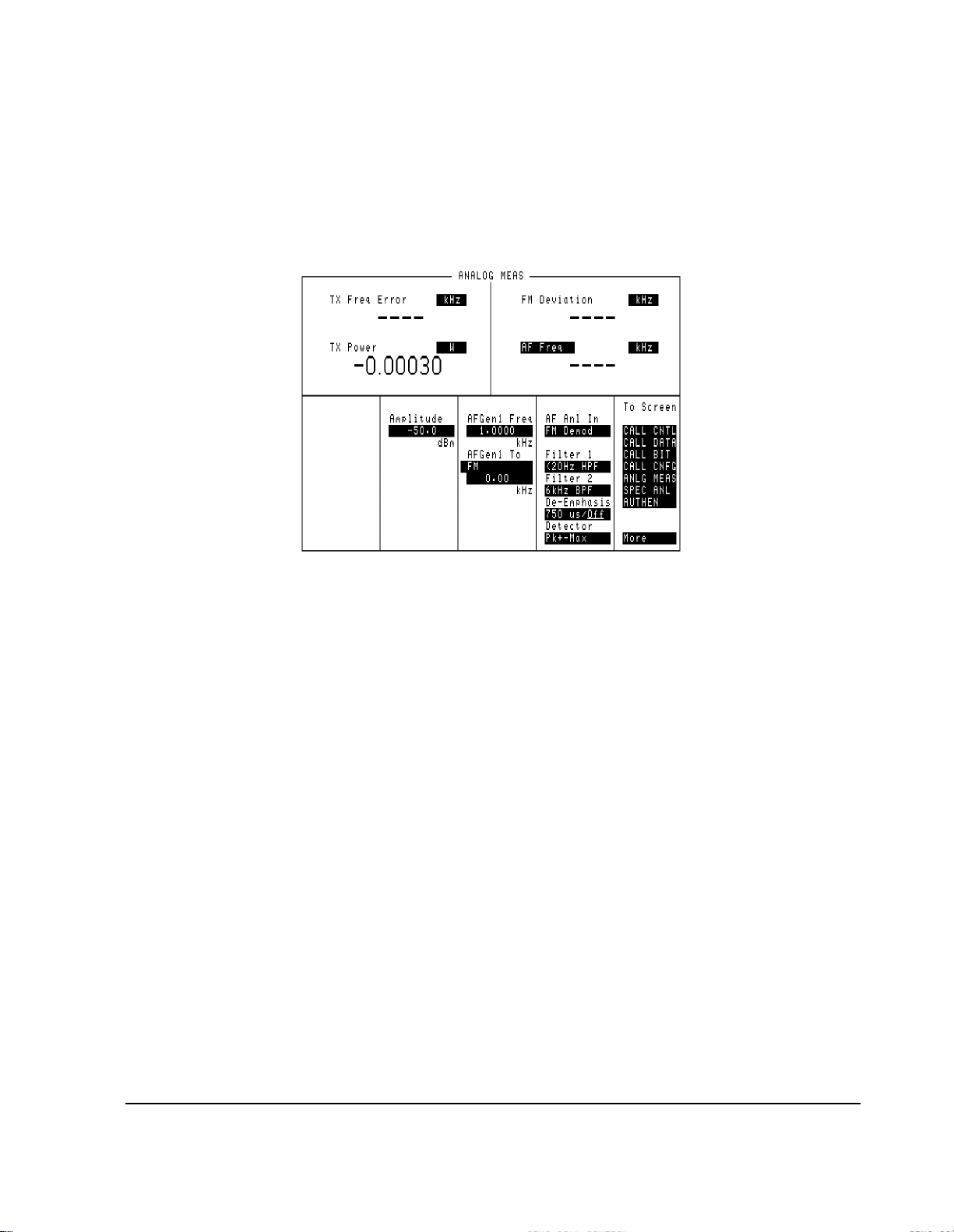
Call Control Screens - ANALOG MEAS
Chapter 3, Description of Screens
Call Control Screens
Figure 8 The ANALOG MEAS Screen
This screen is used to make RF and audio measurements on the mobile station
connected to the Test Set while on an active voice channel.
The T est Set does not monitor the mobile sta tion’s transmitted carrier power while
the ANALOG MEAS screen is displayed. If the power falls below 0.0005 Watts
no error message is displayed nor will the Test Set terminate the call while on the
ANALOG MEAS screen.
87
Page 88

Chapter 3, Description of Scre ens
Call Control Screens
Requirements for Using The ANALOG MEAS Screen
The Test Set must be in the connected state (that is, the Connect annunciator is
lit) in order to use the ANALOG MEAS screen.
The mobile station’s speaker output must be connected to the Test Set’s AUDIO
IN connector and the mobile station’s microphone input must be connected to the
T est Set’s AUDIO OUT connector in order to use the ANALOG MEAS screen. If
the mobile station does not have audio connections the ANALOG MEAS screen
cannot be used.
CAUTION: The host firmware does not monitor the mobile station’s transmitted carrier power while the
ANALOG MEAS screen is displayed. If the power falls below 0.0005 Watts no error message
is displayed nor will the Tes t Set terminate the call while on the ANALOG MEAS screen.
How To Program The ANALOG MEAS Screen
The ANALOG MEAS screen combines some o f the Test Set’ s Audio A nalyzer
fields and some of the Test Set’s
RF Generator fields onto one screen for the
purpose of testing the audio characteristics of the mobile station.
Only those fields which are pertinent to testing the mobile station’s audio
characteristics have been combined onto the
Since the fields on the
ANALOG MEAS screen are imported from other screens
ANALOG MEAS screen.
those fields are programmed exac tly as they would be on their home screen . To set
up the fields, program th e appropriate instrument . To make measurements use the
MEASure subsystem.
88
S:\agilent\e8285\REFGUIDE\MANUAL\screens.chp
Page 89

Call Control Screens - AUTHENTICATION
Chapter 3, Description of Screens
Call Control Screens
Figure 9 The AUTHENTICATION Screen
The AUTHENTICATION screen allows you to enter parameters for
authentication i nt o the Test Set. These parameters are used by the Cave a lgorithm
during Call Processi ng functio ns such as regi strati on, page, and originate to verify
a valid call.
89
Page 90

Chapter 3, Description of Scre ens
Call Control Screens
Call Control Screens - CALL BIT
Figure 10 The CALL BIT Screen
The CALL BIT screen is designed to give an advanced user the capability to modify the
contents of the forward control channel and forward voice channel signaling messages
that are used in all processing messaging protocol.
A messaging protocol is defined as the sequence of messages sent from the Test
Set to the mobile station to perform a desired action, such as registering a mobile
station. Modifying the contents of one or more messages may be required for
testing the robustness of a mobile station’s call processing algorithms or for new
product development.
90
S:\agilent\e8285\REFGUIDE\MANUAL\screens.chp
Page 91

Chapter 3, Description of Screens
Call Control Screens
Using the CALL BIT Screen
Using the CALL BIT screen requires expert knowledge of the call processing
messaging protocols used i n th e syst em selec ted in the
System Type field on the
CALL CONTROL screen.
The CALL BIT screen should not be used to c hange any pa rame ter th at can be se t
on any other Call Processing Subsystem screen. The contents of the applicable
fields on the CALL CONTROL screen and the CALL CONFIGURE screen are
not updated to refle ct any changes made whil e usi ng the CALL BI T scre en. Ther e
is no coupling between the CALL BIT screen and the Test Set.
For example: changing the val ue of the SAT color code field (SCC) in the forward
control channel mobi le station contro l message (MS IntVCh) does not change the
setting of the
SAT: field on the CALL CONTROL screen.
When using the CALL BIT screen the user is responsible for setting the contents
of all messages used in a messaging protocol. When using the CALL BIT screen,
the Call Processing Subsystem sends the correct messages at the correct times as
defined in the applicable industry standard. Message content is the responsibility
of the user.
When the CALL BIT screen is displayed and the Call Processing Subsystem is in
the connected state, the Test Set constantly monitors the station’s transmitted
carrier power . If the Power falls below 0.0 005 W atts, the error message
Loss indicates loss of Voice Channel
will be displayed and the Test
RF Power
Set will terminate the call and return to the active state.
NOTE: In order to ensure that the Test Set makes the correct decisions regarding the presence of the
mobile stations’s RF carrier, the Test Set’s RF power meter shou ld be zeroed before using the
Call Processing Subsystem. Failure to zero the power meter can result in erroneous RF power
measurements.
The field descriptions for each of the messages are given in the "Display Word"
on page 232
Reading the CALL BIT Screen Message Fields This section provides
.
programming information on how to read the contents of individual fields in the
signaling messages available on the
CALL BIT screen.
The syntactical structure for reading the contents of one or more fields from an
individual message is as follows:
General Synt ax
CALLP:<message name>:<field name><?>[<;><additional field><?>]
91
Page 92

Chapter 3, Description of Scre ens
Call Control Screens
Table 3 lists the message names used to access each of the signaling messages
available on the
Table 3 CALL BIT Screen Signaling Message Names
Message Message Name Message Message Name
SPC WORD1 SPOM1/SPOMESSAGE1 BSChalCon BSCConfirmation
SPC WORD2 SPOM2/SPOMESSAGE2 UniqChOrd UCORder
ACCESS ACCess FVC SSD1 FVCSSD1
REG INC RINCrement FVC SSD2 FVCSSD2
REG ID RIDentify FVC SSD3 FVCSSD3
C-FILMESS CFMessage FVCBSCon FVCBSConfirmation
MS WORD1 MSWord FVCUniqCh FVCUChallenge
MSMessOrd MSORder EXT PROT EPFControl | EXTP
MS IntvcH MSVoi ce NMS FVC NFVMessage | NFVC
FVC O Mes FVORder MRI MES MRIMessage | NRMI
FVC C Mes FVVoice WNHO MES W NHMessage
RandChalA RCA NHO MES NHOMessage
RandChalB RCB NTCH ASN NTCAMessage|NTCHA
RAND SSD1 RSSD1 NTMS FVC NTFVMessage|NTFVC
RAND SSD2 RSSD2 WNTHO MES WNTHOMessage
RAND SSD3 RSSD3 NTHO MES NTHOMessage
NCH ASN NCAMessage | NCHA
CALL BIT screen.
Example of Querying A Sing le Field
OUTPUT 714;"CALLP:MESS ’SPC WORD1’"
OUTPUT 714;"CALLP:SPOM1:SID?"
ENTER 714;Sid$
PRINT Sid$
Example Printout
"00000001110011"
92
S:\agilent\e8285\REFGUIDE\MANUAL\screens.chp
Page 93

Chapter 3, Description of Screens
Call Control Screens
Querying Multiple Fields With Single OUTPUT/ENT ER W hen multiple queries are
combined into one command string the Test Set responds by sending one response message containing individual response message units separated by a response message unit
separator (;).
Example of Multiple Queries Comb ined Into One Command String
OUTPUT 714;"CALLP:MESS ’SPC WORD1’"
OUTPUT 714;"CALLP:SPOM1:DCC?;SID?;OHD?"
ENTER 714;Message$
PRINT Message$
Printed Test Set Response Message
"01";"00000001110011";"110"
In order to read individual response message units into individual string variables combined into one ENTER statement the programming language used must recognize the
response message unit separator (;) as an entry terminator for each string in the input list.
If the programming language used cannot recognize the response message unit separator
(;) as an entry terminator then the response message must be read into one string and individual responses parsed out.
Modifying the CALL BIT Screen Message Fields
This section provides
programming information on how to set the contents of individual fields in the
signaling messages available on the
CALL BITS screen.
The syntactical structure for setting the contents of a field in an individual
message is as follows:
General Synt ax’
CALLP:<message name>:<field name><space><’><data string><’>
Table 3, "CALL BIT Screen Signaling Message Names" on page 92 lists the
message names used to access each of the signaling messages available on the
CALL BIT screen.
Example of Modifying A Single Field
OUTPUT 714;"CALLP:SPOM1:SID ’00000001110011’"
Example of Modifying Multiple Fields With One OUTPUT
OUTPUT 714;"CALLP:SPOM1:DCC ’01’;SID ’00000001110011’;OHD ’110’"
93
Page 94

Chapter 3, Description of Scre ens
Call Control Screens
Call Control Screens - CALL CONFIGURE
Figure 11 The CALL CONFIGURE Screen
NOTE: The number of fields displayed on the CALL CONFIGURE screen depends on the selected
system type.
This screen is used to set some of the less commonly used Test Set configuration
parameters.
When the CALL CONFIGURE screen is displayed and the Call Processing
Subsystem is in the connect state, the Test Set constantly monitors the mobile
station’s transmitted carrier power. If the power falls below 0.0005Watts, the error
message
RF Power Loss indicates loss of Voice Channel will be
displayed and the Test Set will terminate the call and return to the active state.
NOTE: In order to ensure that the Test Set makes the correct decisions regarding the presence of the
mobile stations’s RF carrier, the Test Set’s RF power meter shou ld be zeroed before using the
Call Processing Subsystem. Failure to zero the power meter can result in erroneous RF power
measurements.
94
S:\agilent\e8285\REFGUIDE\MANUAL\screens.chp
Page 95

Call Control Screens - CALL DATA
Chapter 3, Description of Screens
Call Control Screens
Figure 12 The CALL DATA Screen
This screen displays the decoded reverse control channel and reverse voice
channel signaling messages received by the Test Set from the mobile station.
Thirteen different decoded messages can be viewed on this screen. The message
to be viewed is selected using the
Display Word field.
95
Page 96

Chapter 3, Description of Scre ens
Call Control Screens
The messages which can be viewed are:
• Reverse Control Channel Messages for Paging, Origination, Orders, and Order
Confirmation.
• RECCW A - Word A - Abbreviated Address Word
• RECCW B - Word B - Extended Address Word
• RECCW C - Word C - Serial Number Word
• RECCW D - Word D - First Word of the Called-Address
• RECCW E - Word E - Second Word of the Called-Address
• Reverse Voice Channel Messages for Order Confirmation.
• RVCOrdCon - Reverse Voice Channel Order Confirmation Message
• Reverse Control Channel Authentication Messages.
• BSChalOrd - Word C - Base Station Challenge Word
• AuthWORD - Word C - Authentication Word
• UniqChCon - Word C - Unique Challenge Order Confirmation Word
• Reverse Voice Channel Authentication Messages.
• RVCOrd - Word one - Reverse Voice Channel Generic Order
• RVCBSChal - Word 2 - Reverse Voice Channel Base Station Challenge Order
• NAMPS Reverse Voice Channel Messages.
• NRVC Ord - Narrow Order or Order Confirmation Message
• MRI Ord - MRI Orde r message
The field descri ptions for e ach of the de coded messag es are given in the Display
field description, on page 232.
Word
When the CALL DATA screen is displayed and the Call Processing Subsystem is
in the connected state, the Test Set constantly monitors the mobile station’s
transmitted carrier power. If the power falls below 0.0005Watts, the error messag e
RF Power Loss indicates loss of Voice Channel will be displayed
and the Test Set will terminate the call and return to the active state.
NOTE: In order to ensure that the Test Set makes the correct decisions regarding the presence of the
mobile stations’s RF carrier, the Test Set’s RF power meter should be zeroed before using the
Call Processing Subsystem. Failure to zero the power meter can result in erroneous RF power
measurements.
96
S:\agilent\e8285\REFGUIDE\MANUAL\screens.chp
Page 97

Reading the CALL DATA Screen Message Fields
This section provides programming information on how to read the individual
fields from the decoded reverse control channel and reverse voice channel
signaling messages available on the
CALL DATA screen.
The syntactical structure for reading one or more fields from an individual
message is as follows:
General Synt ax CALLP:<message name>:<field name><?>[<;><additional
field><?>]
Call Data Screen Message and Field Names Table 4 lists the message names used
to access each of the signaling messages available on the
Table 4 CALL DATA Screen Signaling Message Names
Message Message Name
Chapter 3, Description of Screens
Call Control Screens
CALL DATA screen.
RECCW A RECA
RECCW B RECB
RECCW C RECC
RECCW D RECD
RECCW E RECE
R VCOrdCon RCOConfirm
BSChalOrd BSCOrder
AuthWORD AWORD
UniqChCon UCConfirmation
RVCOrd RVCOrder
RVCBSChal RVCBSChallenge
NRVC Ord NOConfirm
MRI Ord MRIOrder
97
Page 98

Chapter 3, Description of Scre ens
Call Control Screens
Querying a Single Field
Example of Querying A Sing le Field
OUTPUT 714;"CALLP:DATA ’RECCW A’"
OUTPUT 714;"CALLP:RECA:SCM?"
ENTER 714;Scm$
PRINT Scm$
Example Printout
"1110"
Querying Multiple Fields With Single OUTPUT/ENTER
When multiple queries are combined into one command string the Test Set
responds by sending one response message containing individual response
message units separated by a response message unit separator (;).
Example of Multiple Queries Combined Into One Command String
OUTPUT 714;"CALLP:RECA:NAWC?;SER?;EXT?;SCM?;MIN?"
OUTPUT 714;"CALLP:DATA ’RECCW A’"
ENTER 714;Message$
PRINT Message$
Printed Test Set Response Message
"010";"1";"1";"1110";"110111100101101111010101"
In order to read indivi dual res ponse message units into in dividual string variables
combined into one ENTER statement the programming language used must
recognize the response message unit separator (;) as an entry terminator for each
string in the input list. If the programming language used cannot recognize the
response message unit separator (;) as an entry terminator then the response
message must be read into one string and individual responses parsed out.
98
S:\agilent\e8285\REFGUIDE\MANUAL\screens.chp
Page 99

CDMA Authentication Screen
Chapter 3, Description of Screens
CDMA Authentication Screen
Figure 13 The CDMA Authentication Screen
The CDMA Authentication screen provides the necessary features for testing a
CDMA mobile station’s ability to perform call-processing functions with
authentication. On ce a mobile station is regist er ed, va lid A-Key Check Digits can
be generated, and a table displays the authentication parameters sent by the
mobile station, along with the expected value and a passed/failed indication.
99
Page 100

Chapter 3, Description of Scre ens
CDMA Call Control Screen
CDMA Call Control Screen
Figure 14 The CDMA Call Control Screen
This screen allows you to establish a call, terminate a call, and perform handoffs.
100
S:\agilent\e8285\REFGUIDE\MANUAL\screens.chp
 Loading...