

Page 1

User’s Guide
Agilent Technologies
PSG Signal Generators
This guide applies to the following signal generator models:
E8267C PSG Vector Signal Generator
E8257C PSG Analog Signal Generator
E8247C PSG CW Signal Generator
Due to our continuing efforts to improve our products through firmware and hardware revisions, signal
generator design and operation may vary from descriptions in this guide. We recommend that you use the
latest revision of this guide to ensure you have up-to-date product information. Compare the print date of this
guide (see bottom of page) with the latest revision, which can be downloaded from the following website:
www.agilent.com/find/psg
Manufacturing Part Number: E8251-90253
Printed in USA
December 2003
© Copyright 2002, 2003 Agilent Technologies, Inc.
Page 2

Notice
The material contained in this document is provided “as is”, and is subject to being changed, without no tice,
in future editions.
Further, to the maximum extent permitted by applicable law, Agilent disclaims all warranties, either express
or implied with regard to this manual and to any of the Agilent products to which it pertains, including but
not limited to the implied warranties of merchantability and fitness for a particular purpose. Agilent shall not
be liable for errors or for incidental or consequential damages in connection with the furnishing, use, or
performance of this document or any of the Agilent products to which it pertains. Should Agilent have a
written contract with the User and should any of the contract terms conflict with these terms, the contract
terms shall control.
Questions or Comments about our Documentation?
We welcome any questions or comments you may have about our documentation. Please send us an E-mail
at sources_manuals@am.exch.agilent.com.
ii
Page 3

Contents
1. Signal Generator Overview . . . . . . . . . . . . . . . . . . . . . . . . . . . . . . . . . . . . . . . . . . . . . . . . . . . . . . . 1
Signal Generator Models and Features. . . . . . . . . . . . . . . . . . . . . . . . . . . . . . . . . . . . . . . . . . . . . . . . .2
E8247C PSG CW Signal Generator Features. . . . . . . . . . . . . . . . . . . . . . . . . . . . . . . . . . . . . . . . . .2
E8257C PSG Analog Signal Generator Features . . . . . . . . . . . . . . . . . . . . . . . . . . . . . . . . . . . . . . . 3
E8267C PSG Vector Signal Generator Features. . . . . . . . . . . . . . . . . . . . . . . . . . . . . . . . . . . . . . . .4
Options . . . . . . . . . . . . . . . . . . . . . . . . . . . . . . . . . . . . . . . . . . . . . . . . . . . . . . . . . . . . . . . . . . . . . . . . .4
Firmware Upgrades. . . . . . . . . . . . . . . . . . . . . . . . . . . . . . . . . . . . . . . . . . . . . . . . . . . . . . . . . . . . . . . .4
Modes of Operation . . . . . . . . . . . . . . . . . . . . . . . . . . . . . . . . . . . . . . . . . . . . . . . . . . . . . . . . . . . . . . .5
Front Panel . . . . . . . . . . . . . . . . . . . . . . . . . . . . . . . . . . . . . . . . . . . . . . . . . . . . . . . . . . . . . . . . . . . . . .6
1. Display . . . . . . . . . . . . . . . . . . . . . . . . . . . . . . . . . . . . . . . . . . . . . . . . . . . . . . . . . . . . . . . . . . . . .7
2. Softkeys. . . . . . . . . . . . . . . . . . . . . . . . . . . . . . . . . . . . . . . . . . . . . . . . . . . . . . . . . . . . . . . . . . . . .7
3. Knob . . . . . . . . . . . . . . . . . . . . . . . . . . . . . . . . . . . . . . . . . . . . . . . . . . . . . . . . . . . . . . . . . . . . . . .7
4. Amplitude . . . . . . . . . . . . . . . . . . . . . . . . . . . . . . . . . . . . . . . . . . . . . . . . . . . . . . . . . . . . . . . . . . . 7
5. Frequency . . . . . . . . . . . . . . . . . . . . . . . . . . . . . . . . . . . . . . . . . . . . . . . . . . . . . . . . . . . . . . . . . . .7
6. Save. . . . . . . . . . . . . . . . . . . . . . . . . . . . . . . . . . . . . . . . . . . . . . . . . . . . . . . . . . . . . . . . . . . . . . . .7
7. Recall. . . . . . . . . . . . . . . . . . . . . . . . . . . . . . . . . . . . . . . . . . . . . . . . . . . . . . . . . . . . . . . . . . . . . . .7
8. Trigger. . . . . . . . . . . . . . . . . . . . . . . . . . . . . . . . . . . . . . . . . . . . . . . . . . . . . . . . . . . . . . . . . . . . . .8
9. MENUS. . . . . . . . . . . . . . . . . . . . . . . . . . . . . . . . . . . . . . . . . . . . . . . . . . . . . . . . . . . . . . . . . . . . .8
10. Help. . . . . . . . . . . . . . . . . . . . . . . . . . . . . . . . . . . . . . . . . . . . . . . . . . . . . . . . . . . . . . . . . . . . . . .8
11. EXT 1 INPUT. . . . . . . . . . . . . . . . . . . . . . . . . . . . . . . . . . . . . . . . . . . . . . . . . . . . . . . . . . . . . . .8
12. EXT 2 INPUT. . . . . . . . . . . . . . . . . . . . . . . . . . . . . . . . . . . . . . . . . . . . . . . . . . . . . . . . . . . . . . .9
13. LF OUTPUT . . . . . . . . . . . . . . . . . . . . . . . . . . . . . . . . . . . . . . . . . . . . . . . . . . . . . . . . . . . . . . . .9
14. Mod On/Off. . . . . . . . . . . . . . . . . . . . . . . . . . . . . . . . . . . . . . . . . . . . . . . . . . . . . . . . . . . . . . . . .9
15. ALC INPUT . . . . . . . . . . . . . . . . . . . . . . . . . . . . . . . . . . . . . . . . . . . . . . . . . . . . . . . . . . . . . . . .9
16. RF On/Off . . . . . . . . . . . . . . . . . . . . . . . . . . . . . . . . . . . . . . . . . . . . . . . . . . . . . . . . . . . . . . . . . .9
17. Numeric Keypad . . . . . . . . . . . . . . . . . . . . . . . . . . . . . . . . . . . . . . . . . . . . . . . . . . . . . . . . . . . . .9
18. RF OUTPUT. . . . . . . . . . . . . . . . . . . . . . . . . . . . . . . . . . . . . . . . . . . . . . . . . . . . . . . . . . . . . . .10
19. SYNC OUT. . . . . . . . . . . . . . . . . . . . . . . . . . . . . . . . . . . . . . . . . . . . . . . . . . . . . . . . . . . . . . . .10
20. VIDEO OUT. . . . . . . . . . . . . . . . . . . . . . . . . . . . . . . . . . . . . . . . . . . . . . . . . . . . . . . . . . . . . . .10
21. Line Power LED . . . . . . . . . . . . . . . . . . . . . . . . . . . . . . . . . . . . . . . . . . . . . . . . . . . . . . . . . . . .10
22. Power Switch. . . . . . . . . . . . . . . . . . . . . . . . . . . . . . . . . . . . . . . . . . . . . . . . . . . . . . . . . . . . . . .10
23. Standby LED. . . . . . . . . . . . . . . . . . . . . . . . . . . . . . . . . . . . . . . . . . . . . . . . . . . . . . . . . . . . . . .10
24. Incr Set . . . . . . . . . . . . . . . . . . . . . . . . . . . . . . . . . . . . . . . . . . . . . . . . . . . . . . . . . . . . . . . . . . .10
25. GATE/PULSE/TRIGGER INPUT . . . . . . . . . . . . . . . . . . . . . . . . . . . . . . . . . . . . . . . . . . . . . .10
26. Arrows. . . . . . . . . . . . . . . . . . . . . . . . . . . . . . . . . . . . . . . . . . . . . . . . . . . . . . . . . . . . . . . . . . . .11
27. Hold. . . . . . . . . . . . . . . . . . . . . . . . . . . . . . . . . . . . . . . . . . . . . . . . . . . . . . . . . . . . . . . . . . . . . .11
28. Return . . . . . . . . . . . . . . . . . . . . . . . . . . . . . . . . . . . . . . . . . . . . . . . . . . . . . . . . . . . . . . . . . . . .11
29. Display Contrast Decrease . . . . . . . . . . . . . . . . . . . . . . . . . . . . . . . . . . . . . . . . . . . . . . . . . . . . 11
iii
Page 4

Contents
30. Display Contrast Increase. . . . . . . . . . . . . . . . . . . . . . . . . . . . . . . . . . . . . . . . . . . . . . . . . . . . . 11
31. Local . . . . . . . . . . . . . . . . . . . . . . . . . . . . . . . . . . . . . . . . . . . . . . . . . . . . . . . . . . . . . . . . . . . . . 11
32. Preset. . . . . . . . . . . . . . . . . . . . . . . . . . . . . . . . . . . . . . . . . . . . . . . . . . . . . . . . . . . . . . . . . . . . . 11
33. I/Q INPUTS . . . . . . . . . . . . . . . . . . . . . . . . . . . . . . . . . . . . . . . . . . . . . . . . . . . . . . . . . . . . . . .12
34. DATA INPUT . . . . . . . . . . . . . . . . . . . . . . . . . . . . . . . . . . . . . . . . . . . . . . . . . . . . . . . . . . . . . .12
35. DATA CLOCK INPUT. . . . . . . . . . . . . . . . . . . . . . . . . . . . . . . . . . . . . . . . . . . . . . . . . . . . . . .12
36. SYMBOL SYNC INPUT . . . . . . . . . . . . . . . . . . . . . . . . . . . . . . . . . . . . . . . . . . . . . . . . . . . . .12
Front Panel Display . . . . . . . . . . . . . . . . . . . . . . . . . . . . . . . . . . . . . . . . . . . . . . . . . . . . . . . . . . . . . . 13
1. Active Entry Area. . . . . . . . . . . . . . . . . . . . . . . . . . . . . . . . . . . . . . . . . . . . . . . . . . . . . . . . . . . .13
2. Frequency Area. . . . . . . . . . . . . . . . . . . . . . . . . . . . . . . . . . . . . . . . . . . . . . . . . . . . . . . . . . . . . . 13
3. Annunciators. . . . . . . . . . . . . . . . . . . . . . . . . . . . . . . . . . . . . . . . . . . . . . . . . . . . . . . . . . . . . . . .14
4. Digital Modulation Annunciators. . . . . . . . . . . . . . . . . . . . . . . . . . . . . . . . . . . . . . . . . . . . . . . .16
5. Amplitude Area. . . . . . . . . . . . . . . . . . . . . . . . . . . . . . . . . . . . . . . . . . . . . . . . . . . . . . . . . . . . . .16
6. Error Message Area . . . . . . . . . . . . . . . . . . . . . . . . . . . . . . . . . . . . . . . . . . . . . . . . . . . . . . . . . . 16
7. Text Area. . . . . . . . . . . . . . . . . . . . . . . . . . . . . . . . . . . . . . . . . . . . . . . . . . . . . . . . . . . . . . . . . . . 16
8. Softkey Label Area. . . . . . . . . . . . . . . . . . . . . . . . . . . . . . . . . . . . . . . . . . . . . . . . . . . . . . . . . . . 16
Rear Panel. . . . . . . . . . . . . . . . . . . . . . . . . . . . . . . . . . . . . . . . . . . . . . . . . . . . . . . . . . . . . . . . . . . . . .17
1. AC Power Receptacle. . . . . . . . . . . . . . . . . . . . . . . . . . . . . . . . . . . . . . . . . . . . . . . . . . . . . . . . .18
2. GPIB . . . . . . . . . . . . . . . . . . . . . . . . . . . . . . . . . . . . . . . . . . . . . . . . . . . . . . . . . . . . . . . . . . . . . . 18
3. AUXILIARY INTERFACE . . . . . . . . . . . . . . . . . . . . . . . . . . . . . . . . . . . . . . . . . . . . . . . . . . . .18
4. LAN . . . . . . . . . . . . . . . . . . . . . . . . . . . . . . . . . . . . . . . . . . . . . . . . . . . . . . . . . . . . . . . . . . . . . .18
5. STOP SWEEP IN/OUT . . . . . . . . . . . . . . . . . . . . . . . . . . . . . . . . . . . . . . . . . . . . . . . . . . . . . . .19
6. Z-AXIS BLANK/MKRS . . . . . . . . . . . . . . . . . . . . . . . . . . . . . . . . . . . . . . . . . . . . . . . . . . . . . .19
7. SWEEP OUT . . . . . . . . . . . . . . . . . . . . . . . . . . . . . . . . . . . . . . . . . . . . . . . . . . . . . . . . . . . . . . .19
8. TRIGGER OUT . . . . . . . . . . . . . . . . . . . . . . . . . . . . . . . . . . . . . . . . . . . . . . . . . . . . . . . . . . . . .19
9. TRIGGER IN . . . . . . . . . . . . . . . . . . . . . . . . . . . . . . . . . . . . . . . . . . . . . . . . . . . . . . . . . . . . . . .19
10. SOURCE SETTLED . . . . . . . . . . . . . . . . . . . . . . . . . . . . . . . . . . . . . . . . . . . . . . . . . . . . . . . . 19
11. EVENT 1. . . . . . . . . . . . . . . . . . . . . . . . . . . . . . . . . . . . . . . . . . . . . . . . . . . . . . . . . . . . . . . . . . 20
12. EVENT 2 . . . . . . . . . . . . . . . . . . . . . . . . . . . . . . . . . . . . . . . . . . . . . . . . . . . . . . . . . . . . . . . . . 20
13. PATTERN TRIG IN . . . . . . . . . . . . . . . . . . . . . . . . . . . . . . . . . . . . . . . . . . . . . . . . . . . . . . . . . 20
14. BURST GATE IN. . . . . . . . . . . . . . . . . . . . . . . . . . . . . . . . . . . . . . . . . . . . . . . . . . . . . . . . . . .20
15. AUXILIARY I/O . . . . . . . . . . . . . . . . . . . . . . . . . . . . . . . . . . . . . . . . . . . . . . . . . . . . . . . . . . .21
16. Digital Bus . . . . . . . . . . . . . . . . . . . . . . . . . . . . . . . . . . . . . . . . . . . . . . . . . . . . . . . . . . . . . . . . 22
17. WIDEBAND I INPUT . . . . . . . . . . . . . . . . . . . . . . . . . . . . . . . . . . . . . . . . . . . . . . . . . . . . . . .22
18. WIDEBAND Q INPUT . . . . . . . . . . . . . . . . . . . . . . . . . . . . . . . . . . . . . . . . . . . . . . . . . . . . . .22
19. COH (COHERENT CARRIER OUTPUT) . . . . . . . . . . . . . . . . . . . . . . . . . . . . . . . . . . . . . . . 22
20. I OUT . . . . . . . . . . . . . . . . . . . . . . . . . . . . . . . . . . . . . . . . . . . . . . . . . . . . . . . . . . . . . . . . . . . .22
21. I-bar OUT . . . . . . . . . . . . . . . . . . . . . . . . . . . . . . . . . . . . . . . . . . . . . . . . . . . . . . . . . . . . . . . . .23
iv
Page 5

Contents
22. Q OUT. . . . . . . . . . . . . . . . . . . . . . . . . . . . . . . . . . . . . . . . . . . . . . . . . . . . . . . . . . . . . . . . . . . .23
23. Q-bar OUT . . . . . . . . . . . . . . . . . . . . . . . . . . . . . . . . . . . . . . . . . . . . . . . . . . . . . . . . . . . . . . . .23
24. BASEBAND GEN REF IN. . . . . . . . . . . . . . . . . . . . . . . . . . . . . . . . . . . . . . . . . . . . . . . . . . . .23
25. SMI (SOURCE MODULE INTERFACE) . . . . . . . . . . . . . . . . . . . . . . . . . . . . . . . . . . . . . . . .24
26. 10 MHz OUT . . . . . . . . . . . . . . . . . . . . . . . . . . . . . . . . . . . . . . . . . . . . . . . . . . . . . . . . . . . . . .24
27. 10 MHz IN . . . . . . . . . . . . . . . . . . . . . . . . . . . . . . . . . . . . . . . . . . . . . . . . . . . . . . . . . . . . . . . .24
28. 10 MHz EFC (Option UNR). . . . . . . . . . . . . . . . . . . . . . . . . . . . . . . . . . . . . . . . . . . . . . . . . . .24
2. Basic Operation. . . . . . . . . . . . . . . . . . . . . . . . . . . . . . . . . . . . . . . . . . . . . . . . . . . . . . . . . . . . . . . . .25
Using Table Editors. . . . . . . . . . . . . . . . . . . . . . . . . . . . . . . . . . . . . . . . . . . . . . . . . . . . . . . . . . . . . . .26
Table Editor Softkeys . . . . . . . . . . . . . . . . . . . . . . . . . . . . . . . . . . . . . . . . . . . . . . . . . . . . . . . . . . .27
Modifying Table Items in the Data Fields. . . . . . . . . . . . . . . . . . . . . . . . . . . . . . . . . . . . . . . . . . . .27
Configuring the RF Output. . . . . . . . . . . . . . . . . . . . . . . . . . . . . . . . . . . . . . . . . . . . . . . . . . . . . . . . .28
Configuring a Continuous Wave RF Output. . . . . . . . . . . . . . . . . . . . . . . . . . . . . . . . . . . . . . . . . .28
Configuring a Swept RF Output . . . . . . . . . . . . . . . . . . . . . . . . . . . . . . . . . . . . . . . . . . . . . . . . . . .31
Extending the Frequency Range with a mm-Wave Source Module . . . . . . . . . . . . . . . . . . . . . . . .47
Modulating a Signal . . . . . . . . . . . . . . . . . . . . . . . . . . . . . . . . . . . . . . . . . . . . . . . . . . . . . . . . . . . . . .50
Turning On a Modulation Format . . . . . . . . . . . . . . . . . . . . . . . . . . . . . . . . . . . . . . . . . . . . . . . . . .50
Applying a Modulation Format to the RF Output. . . . . . . . . . . . . . . . . . . . . . . . . . . . . . . . . . . . . .51
Using Data Storage Functions . . . . . . . . . . . . . . . . . . . . . . . . . . . . . . . . . . . . . . . . . . . . . . . . . . . . . .52
Using the Memory Catalog. . . . . . . . . . . . . . . . . . . . . . . . . . . . . . . . . . . . . . . . . . . . . . . . . . . . . . .52
Using the Instrument State Register . . . . . . . . . . . . . . . . . . . . . . . . . . . . . . . . . . . . . . . . . . . . . . . .54
Enabling Options . . . . . . . . . . . . . . . . . . . . . . . . . . . . . . . . . . . . . . . . . . . . . . . . . . . . . . . . . . . . . . . .57
Enabling a Software Option . . . . . . . . . . . . . . . . . . . . . . . . . . . . . . . . . . . . . . . . . . . . . . . . . . . . . .57
3. Optimizing Performance. . . . . . . . . . . . . . . . . . . . . . . . . . . . . . . . . . . . . . . . . . . . . . . . . . . . . . . . . .59
Selecting ALC Bandwidth . . . . . . . . . . . . . . . . . . . . . . . . . . . . . . . . . . . . . . . . . . . . . . . . . . . . . . . . .59
To Select an ALC Bandwidth . . . . . . . . . . . . . . . . . . . . . . . . . . . . . . . . . . . . . . . . . . . . . . . . . . . . .59
Using External Leveling. . . . . . . . . . . . . . . . . . . . . . . . . . . . . . . . . . . . . . . . . . . . . . . . . . . . . . . . . . .60
To Level with Detectors and Couplers/Splitters . . . . . . . . . . . . . . . . . . . . . . . . . . . . . . . . . . . . . . .60
To Level with a mm-Wave Source Module. . . . . . . . . . . . . . . . . . . . . . . . . . . . . . . . . . . . . . . . . . .63
Creating and Applying User Flatness Correction. . . . . . . . . . . . . . . . . . . . . . . . . . . . . . . . . . . . . . . .64
Creating a User Flatness Correction Array. . . . . . . . . . . . . . . . . . . . . . . . . . . . . . . . . . . . . . . . . . .64
Creating a User Flatness Correction Array with a mm-Wave Source Module. . . . . . . . . . . . . . . .69
Adjusting Reference Oscillator Bandwidth (Option UNR) . . . . . . . . . . . . . . . . . . . . . . . . . . . . . . . .76
To Select the Reference Oscillator Bandwidth. . . . . . . . . . . . . . . . . . . . . . . . . . . . . . . . . . . . . . . .76
To Restore Factory Default Settings: . . . . . . . . . . . . . . . . . . . . . . . . . . . . . . . . . . . . . . . . . . . . . . .76
v
Page 6

Contents
4. Analog Modulation. . . . . . . . . . . . . . . . . . . . . . . . . . . . . . . . . . . . . . . . . . . . . . . . . . . . . . . . . . . . . . 77
Analog Modulation Waveforms . . . . . . . . . . . . . . . . . . . . . . . . . . . . . . . . . . . . . . . . . . . . . . . . . . . . .78
Configuring AM. . . . . . . . . . . . . . . . . . . . . . . . . . . . . . . . . . . . . . . . . . . . . . . . . . . . . . . . . . . . . . . . . 79
To Set the Carrier Frequency . . . . . . . . . . . . . . . . . . . . . . . . . . . . . . . . . . . . . . . . . . . . . . . . . . . . . 79
To Set the RF Output Amplitude . . . . . . . . . . . . . . . . . . . . . . . . . . . . . . . . . . . . . . . . . . . . . . . . . .79
To Set the AM Depth and Rate. . . . . . . . . . . . . . . . . . . . . . . . . . . . . . . . . . . . . . . . . . . . . . . . . . . . 79
To Turn on Amplitude Modulation. . . . . . . . . . . . . . . . . . . . . . . . . . . . . . . . . . . . . . . . . . . . . . . . .79
Configuring FM . . . . . . . . . . . . . . . . . . . . . . . . . . . . . . . . . . . . . . . . . . . . . . . . . . . . . . . . . . . . . . . . .80
To Set the RF Output Frequency . . . . . . . . . . . . . . . . . . . . . . . . . . . . . . . . . . . . . . . . . . . . . . . . . . 80
To Set the RF Output Amplitude . . . . . . . . . . . . . . . . . . . . . . . . . . . . . . . . . . . . . . . . . . . . . . . . . .80
To Set the FM Deviation and Rate . . . . . . . . . . . . . . . . . . . . . . . . . . . . . . . . . . . . . . . . . . . . . . . . .80
To Activate FM. . . . . . . . . . . . . . . . . . . . . . . . . . . . . . . . . . . . . . . . . . . . . . . . . . . . . . . . . . . . . . . .80
Configuring ΦM. . . . . . . . . . . . . . . . . . . . . . . . . . . . . . . . . . . . . . . . . . . . . . . . . . . . . . . . . . . . . . . . . 81
To Set the RF Output Frequency . . . . . . . . . . . . . . . . . . . . . . . . . . . . . . . . . . . . . . . . . . . . . . . . . . 81
To Set the RF Output Amplitude . . . . . . . . . . . . . . . . . . . . . . . . . . . . . . . . . . . . . . . . . . . . . . . . . .81
To Set the FM Deviation and Rate . . . . . . . . . . . . . . . . . . . . . . . . . . . . . . . . . . . . . . . . . . . . . . . . .81
To Activate FM. . . . . . . . . . . . . . . . . . . . . . . . . . . . . . . . . . . . . . . . . . . . . . . . . . . . . . . . . . . . . . . .81
Configuring Pulse Modulation. . . . . . . . . . . . . . . . . . . . . . . . . . . . . . . . . . . . . . . . . . . . . . . . . . . . . .82
To Set the RF Output Frequency . . . . . . . . . . . . . . . . . . . . . . . . . . . . . . . . . . . . . . . . . . . . . . . . . . 82
To Set the RF Output Amplitude . . . . . . . . . . . . . . . . . . . . . . . . . . . . . . . . . . . . . . . . . . . . . . . . . .82
To Set the Pulse Period and Width . . . . . . . . . . . . . . . . . . . . . . . . . . . . . . . . . . . . . . . . . . . . . . . . . 82
To Activate Pulse Modulation . . . . . . . . . . . . . . . . . . . . . . . . . . . . . . . . . . . . . . . . . . . . . . . . . . . . 82
Configuring the LF Output . . . . . . . . . . . . . . . . . . . . . . . . . . . . . . . . . . . . . . . . . . . . . . . . . . . . . . . . 83
To Configure the LF Output with an Internal Modulation Source. . . . . . . . . . . . . . . . . . . . . . . . .84
To Configure the LF Output with a Function Generator Source . . . . . . . . . . . . . . . . . . . . . . . . . . 85
5. Dual Arbitrary Waveform Generator. . . . . . . . . . . . . . . . . . . . . . . . . . . . . . . . . . . . . . . . . . . . . . . . 87
Arbitrary (ARB) Waveform File Headers . . . . . . . . . . . . . . . . . . . . . . . . . . . . . . . . . . . . . . . . . . . . .88
Creating a File Header for a Modulation Format Waveform . . . . . . . . . . . . . . . . . . . . . . . . . . . . .89
Modifying Header Information in a Modulation Format . . . . . . . . . . . . . . . . . . . . . . . . . . . . . . . .90
Storing Header Information for a Dual ARB Player Waveform Sequence . . . . . . . . . . . . . . . . . . 95
Modifying and Viewing Header Information in the Dual ARB Player . . . . . . . . . . . . . . . . . . . . .95
Playing a Waveform File that Contains a Header. . . . . . . . . . . . . . . . . . . . . . . . . . . . . . . . . . . . . .98
Using the Dual ARB Waveform Player . . . . . . . . . . . . . . . . . . . . . . . . . . . . . . . . . . . . . . . . . . . . . . .99
Accessing the Dual ARB Player. . . . . . . . . . . . . . . . . . . . . . . . . . . . . . . . . . . . . . . . . . . . . . . . . . . 99
Creating Waveform Segments . . . . . . . . . . . . . . . . . . . . . . . . . . . . . . . . . . . . . . . . . . . . . . . . . . .100
Building and Storing a Waveform Sequence . . . . . . . . . . . . . . . . . . . . . . . . . . . . . . . . . . . . . . . .101
Playing a Waveform . . . . . . . . . . . . . . . . . . . . . . . . . . . . . . . . . . . . . . . . . . . . . . . . . . . . . . . . . . . 102
vi
Page 7

Contents
Editing a Waveform Sequence . . . . . . . . . . . . . . . . . . . . . . . . . . . . . . . . . . . . . . . . . . . . . . . . . . .102
Storing and Loading Waveform Segments . . . . . . . . . . . . . . . . . . . . . . . . . . . . . . . . . . . . . . . . . .103
Renaming a Waveform Segment. . . . . . . . . . . . . . . . . . . . . . . . . . . . . . . . . . . . . . . . . . . . . . . . . .103
Using Waveform Markers. . . . . . . . . . . . . . . . . . . . . . . . . . . . . . . . . . . . . . . . . . . . . . . . . . . . . . . . .104
To Place a Marker at the First Point within a Waveform Segment . . . . . . . . . . . . . . . . . . . . . . . .104
To Place a Marker Across a Range of Points within a Waveform Segment . . . . . . . . . . . . . . . . .104
To Place Repetitively Spaced Markers within a Waveform Segment. . . . . . . . . . . . . . . . . . . . . .105
To Use Marker 2 to Blank the RF Output. . . . . . . . . . . . . . . . . . . . . . . . . . . . . . . . . . . . . . . . . . .105
To Toggle Markers in an Existing Waveform Sequence. . . . . . . . . . . . . . . . . . . . . . . . . . . . . . . .106
To Toggle Markers As You Create a Waveform Sequence. . . . . . . . . . . . . . . . . . . . . . . . . . . . . .107
To Verify Marker Operation . . . . . . . . . . . . . . . . . . . . . . . . . . . . . . . . . . . . . . . . . . . . . . . . . . . . .107
Waveform Marker Concepts . . . . . . . . . . . . . . . . . . . . . . . . . . . . . . . . . . . . . . . . . . . . . . . . . . . . .108
Using Waveform Triggers. . . . . . . . . . . . . . . . . . . . . . . . . . . . . . . . . . . . . . . . . . . . . . . . . . . . . . . . .111
To Use Segment Advance Triggering. . . . . . . . . . . . . . . . . . . . . . . . . . . . . . . . . . . . . . . . . . . . . .111
Using Waveform Clipping . . . . . . . . . . . . . . . . . . . . . . . . . . . . . . . . . . . . . . . . . . . . . . . . . . . . . . . .112
To Configure Circular Clipping . . . . . . . . . . . . . . . . . . . . . . . . . . . . . . . . . . . . . . . . . . . . . . . . . .112
To Configure Rectangular Clipping . . . . . . . . . . . . . . . . . . . . . . . . . . . . . . . . . . . . . . . . . . . . . . .112
Waveform Clipping Concepts. . . . . . . . . . . . . . . . . . . . . . . . . . . . . . . . . . . . . . . . . . . . . . . . . . . .113
6. Custom Arb Waveform Generator . . . . . . . . . . . . . . . . . . . . . . . . . . . . . . . . . . . . . . . . . . . . . . . . .119
Overview. . . . . . . . . . . . . . . . . . . . . . . . . . . . . . . . . . . . . . . . . . . . . . . . . . . . . . . . . . . . . . . . . . . . . .120
Working with Predefined Setups (Modes) . . . . . . . . . . . . . . . . . . . . . . . . . . . . . . . . . . . . . . . . . . . .121
Selecting a Custom ARB Setup or a Custom Digital Modulation State . . . . . . . . . . . . . . . . . . . .121
Working with User-Defined Setups (Modes)-Custom Arb Only . . . . . . . . . . . . . . . . . . . . . . . . . . .122
Modifying a Single-Carrier NADC Setup. . . . . . . . . . . . . . . . . . . . . . . . . . . . . . . . . . . . . . . . . . .122
Customizing a Multicarrier Setup. . . . . . . . . . . . . . . . . . . . . . . . . . . . . . . . . . . . . . . . . . . . . . . . .123
Recalling a User-Defined Custom Digital Modulation State . . . . . . . . . . . . . . . . . . . . . . . . . . . .124
Working with Filters . . . . . . . . . . . . . . . . . . . . . . . . . . . . . . . . . . . . . . . . . . . . . . . . . . . . . . . . . . . . .125
Using a Predefined FIR Filter. . . . . . . . . . . . . . . . . . . . . . . . . . . . . . . . . . . . . . . . . . . . . . . . . . . .126
Using a User-Defined FIR Filter. . . . . . . . . . . . . . . . . . . . . . . . . . . . . . . . . . . . . . . . . . . . . . . . . .127
Working with Symbol Rates. . . . . . . . . . . . . . . . . . . . . . . . . . . . . . . . . . . . . . . . . . . . . . . . . . . . . . .133
To Set a Symbol Rate . . . . . . . . . . . . . . . . . . . . . . . . . . . . . . . . . . . . . . . . . . . . . . . . . . . . . . . . . .133
To Restore the Default Symbol Rate (Custom Real Time I/Q Only) . . . . . . . . . . . . . . . . . . . . . .133
Working with Modulation Types . . . . . . . . . . . . . . . . . . . . . . . . . . . . . . . . . . . . . . . . . . . . . . . . . . .136
To Select a Predefined Modulation Type . . . . . . . . . . . . . . . . . . . . . . . . . . . . . . . . . . . . . . . . . . .136
To Use a User-Defined Modulation Type (Real Time I/Q Only) . . . . . . . . . . . . . . . . . . . . . . . . .137
Configuring Hardware . . . . . . . . . . . . . . . . . . . . . . . . . . . . . . . . . . . . . . . . . . . . . . . . . . . . . . . . . . .143
To Set a Delayed, Positive Polarity, External Single Trigger . . . . . . . . . . . . . . . . . . . . . . . . . . . .143
vii
Page 8

Contents
To Set the ARB Reference . . . . . . . . . . . . . . . . . . . . . . . . . . . . . . . . . . . . . . . . . . . . . . . . . . . . . .144
7. Custom Real Time I/Q Baseband . . . . . . . . . . . . . . . . . . . . . . . . . . . . . . . . . . . . . . . . . . . . . . . . . 145
Overview . . . . . . . . . . . . . . . . . . . . . . . . . . . . . . . . . . . . . . . . . . . . . . . . . . . . . . . . . . . . . . . . . . . . .146
Working with Predefined Setups (Modes) . . . . . . . . . . . . . . . . . . . . . . . . . . . . . . . . . . . . . . . . . . . . 146
Selecting a Predefined Real Time Modulation Setup. . . . . . . . . . . . . . . . . . . . . . . . . . . . . . . . . . 146
Deselecting a Predefined Real Time Modulation Setup . . . . . . . . . . . . . . . . . . . . . . . . . . . . . . . . 146
Working with Data Patterns . . . . . . . . . . . . . . . . . . . . . . . . . . . . . . . . . . . . . . . . . . . . . . . . . . . . . . . 147
Using a Predefined Data Pattern. . . . . . . . . . . . . . . . . . . . . . . . . . . . . . . . . . . . . . . . . . . . . . . . . . 148
Using a User-Defined Data Pattern. . . . . . . . . . . . . . . . . . . . . . . . . . . . . . . . . . . . . . . . . . . . . . . .149
Using an Externally Supplied Data Pattern . . . . . . . . . . . . . . . . . . . . . . . . . . . . . . . . . . . . . . . . .152
Working with Burst Shapes . . . . . . . . . . . . . . . . . . . . . . . . . . . . . . . . . . . . . . . . . . . . . . . . . . . . . . .153
Configuring the Burst Rise and Fall Parameters . . . . . . . . . . . . . . . . . . . . . . . . . . . . . . . . . . . . .154
Using User-Defined Burst Shape Curves. . . . . . . . . . . . . . . . . . . . . . . . . . . . . . . . . . . . . . . . . . .155
Configuring Hardware . . . . . . . . . . . . . . . . . . . . . . . . . . . . . . . . . . . . . . . . . . . . . . . . . . . . . . . . . . . 158
To Set the BBG Reference . . . . . . . . . . . . . . . . . . . . . . . . . . . . . . . . . . . . . . . . . . . . . . . . . . . . . .158
To Set the External DATA CLOCK to Receive Input as Either Normal or Symbol . . . . . . . . . . 159
To Set the BBG DATA CLOCK to External or Internal. . . . . . . . . . . . . . . . . . . . . . . . . . . . . . . . 159
To Adjust the I/Q Scaling . . . . . . . . . . . . . . . . . . . . . . . . . . . . . . . . . . . . . . . . . . . . . . . . . . . . . . .159
Working with Phase Polarity . . . . . . . . . . . . . . . . . . . . . . . . . . . . . . . . . . . . . . . . . . . . . . . . . . . . . . 160
To Set Phase Polarity to Normal or Inverted . . . . . . . . . . . . . . . . . . . . . . . . . . . . . . . . . . . . . . . .160
Working with Differential Data Encoding . . . . . . . . . . . . . . . . . . . . . . . . . . . . . . . . . . . . . . . . . . . .160
Understanding Differential Encoding . . . . . . . . . . . . . . . . . . . . . . . . . . . . . . . . . . . . . . . . . . . . . .160
Using Differential Encoding. . . . . . . . . . . . . . . . . . . . . . . . . . . . . . . . . . . . . . . . . . . . . . . . . . . . . 165
8. Multitone Waveform Generator . . . . . . . . . . . . . . . . . . . . . . . . . . . . . . . . . . . . . . . . . . . . . . . . . . 169
Overview . . . . . . . . . . . . . . . . . . . . . . . . . . . . . . . . . . . . . . . . . . . . . . . . . . . . . . . . . . . . . . . . . . . . .170
Creating, Viewing, and Optimizing Multitone Waveforms . . . . . . . . . . . . . . . . . . . . . . . . . . . . . . .171
To Create a Custom Multitone Waveform . . . . . . . . . . . . . . . . . . . . . . . . . . . . . . . . . . . . . . . . . .171
To View a Multitone Waveform . . . . . . . . . . . . . . . . . . . . . . . . . . . . . . . . . . . . . . . . . . . . . . . . . .172
To Edit the Multitone Setup Table . . . . . . . . . . . . . . . . . . . . . . . . . . . . . . . . . . . . . . . . . . . . . . . .173
To Minimize Carrier Feedthrough . . . . . . . . . . . . . . . . . . . . . . . . . . . . . . . . . . . . . . . . . . . . . . . .175
To Determine Peak to Average Characteristics. . . . . . . . . . . . . . . . . . . . . . . . . . . . . . . . . . . . . . .177
9. Two-Tone Waveform Generator . . . . . . . . . . . . . . . . . . . . . . . . . . . . . . . . . . . . . . . . . . . . . . . . . . . 179
Overview . . . . . . . . . . . . . . . . . . . . . . . . . . . . . . . . . . . . . . . . . . . . . . . . . . . . . . . . . . . . . . . . . . . . .180
Creating, Viewing, and Modifying Two-Tone Waveforms . . . . . . . . . . . . . . . . . . . . . . . . . . . . . . .181
To Create a Two-Tone Waveform. . . . . . . . . . . . . . . . . . . . . . . . . . . . . . . . . . . . . . . . . . . . . . . . . 1 81
viii
Page 9

Contents
To View a Two-Tone Waveform. . . . . . . . . . . . . . . . . . . . . . . . . . . . . . . . . . . . . . . . . . . . . . . . . .182
To Minimize Carrier Feedthrough. . . . . . . . . . . . . . . . . . . . . . . . . . . . . . . . . . . . . . . . . . . . . . . . .184
To Change the Alignment of a Two-Tone Waveform. . . . . . . . . . . . . . . . . . . . . . . . . . . . . . . . . .186
10. Troubleshooting. . . . . . . . . . . . . . . . . . . . . . . . . . . . . . . . . . . . . . . . . . . . . . . . . . . . . . . . . . . . . . .187
RF Output Power Problems . . . . . . . . . . . . . . . . . . . . . . . . . . . . . . . . . . . . . . . . . . . . . . . . . . . . . . .189
RF Output Power too Low . . . . . . . . . . . . . . . . . . . . . . . . . . . . . . . . . . . . . . . . . . . . . . . . . . . . . .189
The Power Supply has Shut Down . . . . . . . . . . . . . . . . . . . . . . . . . . . . . . . . . . . . . . . . . . . . . . . .189
Signal Loss While Working with a Mixer. . . . . . . . . . . . . . . . . . . . . . . . . . . . . . . . . . . . . . . . . . .190
Signal Loss While Working with a Spectrum Analyzer . . . . . . . . . . . . . . . . . . . . . . . . . . . . . . . .192
No Modulation at the RF Output . . . . . . . . . . . . . . . . . . . . . . . . . . . . . . . . . . . . . . . . . . . . . . . . . . .193
Sweep Problems . . . . . . . . . . . . . . . . . . . . . . . . . . . . . . . . . . . . . . . . . . . . . . . . . . . . . . . . . . . . . . . . 1 94
Sweep Appears to be Stalled. . . . . . . . . . . . . . . . . . . . . . . . . . . . . . . . . . . . . . . . . . . . . . . . . . . . .194
Cannot Turn Off Sweep Mode . . . . . . . . . . . . . . . . . . . . . . . . . . . . . . . . . . . . . . . . . . . . . . . . . . .194
Incorrect List Sweep Dwell Time . . . . . . . . . . . . . . . . . . . . . . . . . . . . . . . . . . . . . . . . . . . . . . . . .195
List Sweep Information is Missing from a Recalled Register . . . . . . . . . . . . . . . . . . . . . . . . . . .195
Data Storage Problems . . . . . . . . . . . . . . . . . . . . . . . . . . . . . . . . . . . . . . . . . . . . . . . . . . . . . . . . . . .196
Registers With Previously Stored Instrument States are Empty. . . . . . . . . . . . . . . . . . . . . . . . . .196
Saved Instrument State, but Register is Empty or Contains Wrong State. . . . . . . . . . . . . . . . . . .196
Cannot Turn Off Help Mode . . . . . . . . . . . . . . . . . . . . . . . . . . . . . . . . . . . . . . . . . . . . . . . . . . . . . . .197
Signal Generator Locks Up. . . . . . . . . . . . . . . . . . . . . . . . . . . . . . . . . . . . . . . . . . . . . . . . . . . . . . . .198
Fail-Safe Recovery Sequence . . . . . . . . . . . . . . . . . . . . . . . . . . . . . . . . . . . . . . . . . . . . . . . . . . . . 1 98
Error Messages . . . . . . . . . . . . . . . . . . . . . . . . . . . . . . . . . . . . . . . . . . . . . . . . . . . . . . . . . . . . . . . . .200
Error Message File . . . . . . . . . . . . . . . . . . . . . . . . . . . . . . . . . . . . . . . . . . . . . . . . . . . . . . . . . . . .200
Error Message Format. . . . . . . . . . . . . . . . . . . . . . . . . . . . . . . . . . . . . . . . . . . . . . . . . . . . . . . . . .201
Error Message Types. . . . . . . . . . . . . . . . . . . . . . . . . . . . . . . . . . . . . . . . . . . . . . . . . . . . . . . . . . .202
Returning a Signal Generator to Agilent Technologies . . . . . . . . . . . . . . . . . . . . . . . . . . . . . . . . . .203
ix
Page 10

Contents
x
Page 11

1 Signal Generator Overview
In the following sections, this chapter describes the models, options, and features available for Agilent PSG
signal generators. The modes of operation, front panel user interface, as well as front and rear panel
connectors are also described.
• “Signal Generator Models and Features” on page 2
• “Options” on page 4
• “Firmware Upgrades” on page 4
• “Modes of Operation” on page 5
• “Front Panel” on page 6
• “Front Panel Display” on page 13
• “Rear Panel” on page 17
1
Page 12

Signal Generator Overview
Signal Generator Models and Features
Signal Generator Models and Features
Table 1-1 lists the available PSG signal generator models al on g w it h thei r o utpu t si gn al t ypes and frequency
range.
Table 1-1 PSG Signal Generator Models
Model Type Frequency Range
E8247C PSG CW signal generator CW 250 kHz to 20 GHz, or
250 kHz to 40 GHz
E8257C PSG analog signal generator Analog 250 kHz to 20 GHz, or
250 kHz to 40 GHz
E8267C PSG vector signal generator Vector 250 kHz to 20 GHz
E8247C PSG CW Signal Generator Features
An E8247C PSG CW signal generator includes the following features:
• CW output from 250 kHz to 20 GHz or 40 GHz
• frequency resolution to 0.001 Hz
• list and step sweep of frequency and amplitude, with multiple trigger sources
• user flatness correction
• external diode detector leveling
• automatic leveling control (ALC) on and off modes; power calibration in ALC-off mode is available,
even without power search
• 10 MHz reference oscillator with external output
• RS-232, GPIB, and 10Base-T LAN I/O interfaces
• a millimeter head interface that is compatible with Agilent 83550 Series millimeter heads (for frequency
extension up to 110 GHz)
2 Chapter 1
Page 13

Signal Generator Overview
Signal Generator Models and Features
E8257C PSG Analog Signal Generator Features
An E8257C PSG analog signal generator provides all the functionality of an E8247C PSG CW signa l
generator and adds the following features:
• open-loop or closed-loop AM
• dc-synthesized FM to 10 MHz rates; maximum deviation depends on the carrier frequency
• phase modulation (ΦM)
• pulse modulation
• external modulation inputs for AM, FM, ΦM, and pulse
• simultaneous modulation configurations (except: FM with ΦM or Linear AM with Exponential AM)
• an internal pulse generator that includes the following:
— selectable pulse modes: internal square, internal free-run, internal triggered, internal doublet, internal
gated, and external pulse; internal triggered, internal doublet, and internal gated require an
external trigger source
— adjustable pulse rate
— adjustable pulse period
— adjustable pulse width
— adjustable pulse delay
— selectable external pulse triggering: positive or negative
• dual function generators that includes the following:
—50Ω low frequency output, 0 to 3V
— selectable waveforms: sine, dual-sine, swept-sine, triangle, positive ramp, negative ramp, squ a re,
uniform noise, Gaussian noise, and dc
— adjustable frequency modulation rates
— selectable triggering in list and step sweep modes: free run (auto), trigger key (single), bus (remote),
and external
Chapter 1 3
, available through LF OUTPUT
p
Page 14

Signal Generator Overview
Options
E8267C PSG Vector Signal Generator Features
An E8267C PSG vector signal generator provides all the functionality of an E8257C PSG analog signal
generator, and adds the following features:
• internal I/Q modulator
• external analog I/Q inputs
• single-ended and differential analog I/Q outputs
Options
PSG signal generators have hardware, firmware, software, and documentation options. The data sheet
shipped with your signal generator provides an overview of available options. For details , refer to the
Agilent Technologies website.
1. Open: www.agilent.com/find/psg
2. Select the desired model.
3. Click
View compl ete price list.
Firmware Upgrades
The firmware in your signal generator may be upgraded when new firmware is released. New firmware
releases may contain signal generator features and functionality not available in previous firmware releases.
To inquire about the availability of new signal generator firmware, contact Agilent at
http://www.agil ent.com/f ind/upgr adeass istant, or call the appropriate number listed in
Table 10-1 on page 203.
4 Chapter 1
Page 15

Signal Generator Overview
Modes of Operation
Modes of Operation
All PSG signal generator models can be used in CW mode:
• CW mode produces a single carrier signal.
— If you have an E8247CPSG CW signal generator, you can produce a CW single carrier signal
without modulation.
— If you have an E8257C PSG analog signal generator, you can produce a CW single carrier signal
without modulation, or you can add AM, FM, ΦM, or Pulse modulation to produce a single carrier
modulated signal; some of these modulations can be used together.
— If you have an E8267C PSG vector signal generator, you can produce a CW single carrier signal
without modulation, or you can add AM, FM, ΦM, Pulse, or I/Q modulation to produce a single
carrier modulated signal; some of these modulations can be used together.
In addition to CW and analog mode, all of the following modes are also avai lable t o the E826 7C PS G vecto r
signal generator:
• Custom Arb Waveform Generator mode can produce a single modulated carrier or multiple mod ul ated
carriers. Each modulated carrier waveform mu st be calcul ated and generated before it can be output; this
signal generation occurs on the internal baseband generator (Option 002/602). Once a waveform has
been created, it can be stored and recalled which enables repeatable playback of test signals. To learn
more, refer to “Custom Arb Waveform Generator” on page 119.
• Custom Real Time I/Q Baseband mode produces a single carrier, but it can be modulated with real time
data that allows real time control over all of the parameters that affect the signal. The single carrier signal
that is produced can be modified by applying various data patterns, filters, symbol rates, modulation
types, and burst shapes. To learn more, refer to “Custom Real Time I/Q Baseband” on page 145.
• Two Tone mode produces two separate carrier signals without any kind of modulation; the frequency
spacing between the two carrier signals is adjustable as well as the amplitude of both carriers. To learn
more, refer to “Two-Tone Waveform Generator” on page 179.
• Multitone mode produces any number of carrier signals without any kind of modulation; like Two Tone
mode, the frequency spacing between all carrier signals is adjustable as well as the amplitude of all
carriers. To learn more, refer to “Multitone Waveform Generator” on page 169.
• Dual ARB mode is used to control the playback sequence of wavefo rm seg ments that have been written
into the ARB memory located on the internal baseband generator (Option 002/602). These waveforms
can be generated using the internal baseband generator, in Custom Arb Waveform Generator mode, or
downloaded through a remote interface into the ARB memory. To learn more, refer to “Dual Arbitrary
Waveform Generator” on page 87.
Chapter 1 5
Page 16
Signal Generator Overview
Front Panel
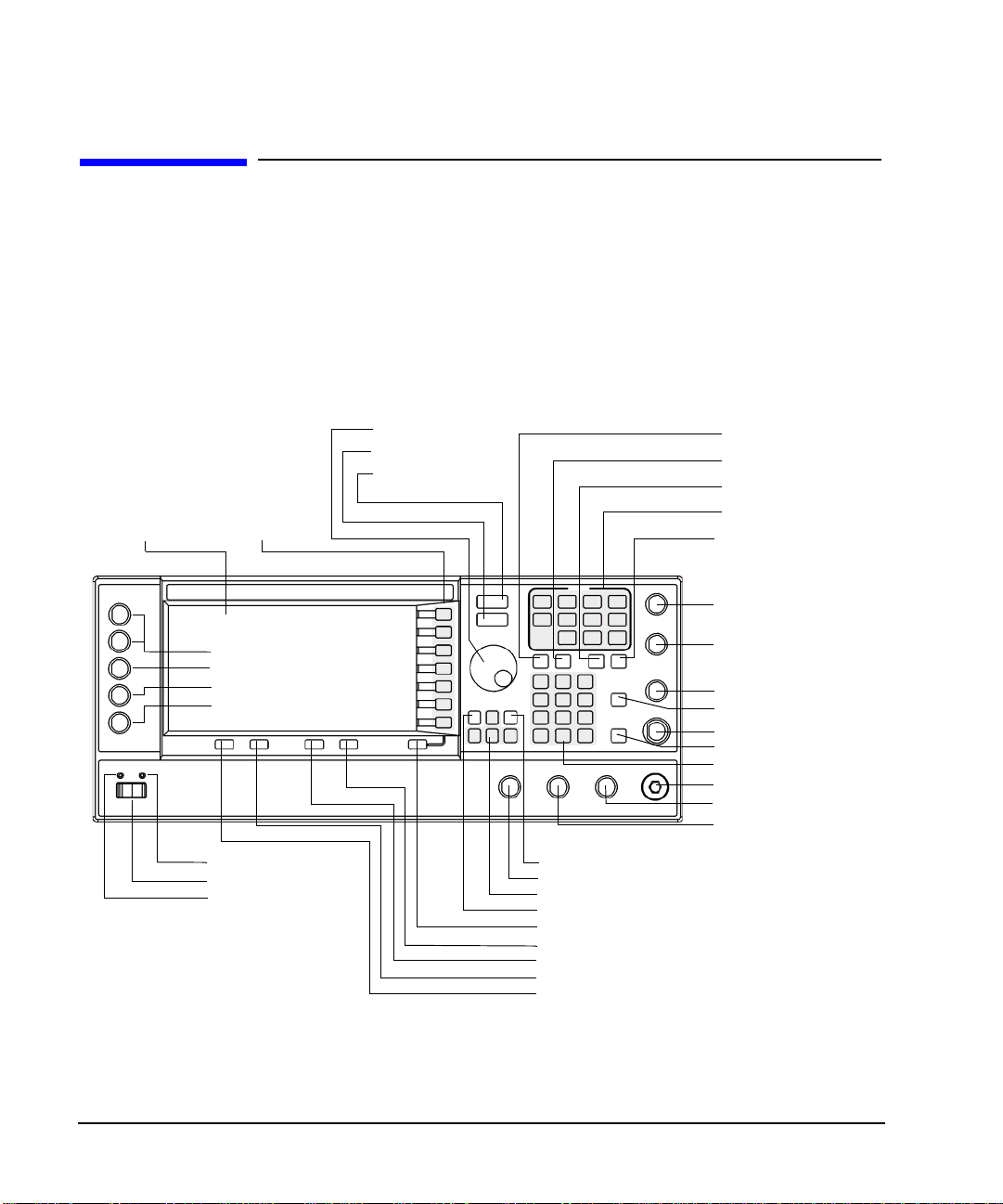
Front Panel
Figure 1-1 shows the E8267C PSG vector signal generator front panel with a list of items called out that
enable you to define, monitor, and manage input and output characteristics.
The description of each item also applies to both the E8257C PSG analog signal generator and the
E8247C PSG CW signal generator front panels. Not all items being described are available on every signal
generator; the list of items that your particular signal generator has is depen dent on its model and options.
Figure 1-1 Front Panel Diagram (E8267C PSG Vector Signal Generator)
1. Display
2. Softkeys
E8267C Only
33. I/Q INPUTS
34. DATA INPUT
35. DATA CLOCK
36. SYMBOL SYNC
21. Line Power LED
22. Power Switch
23. Sta ndby LED
3. Knob
4. Amplitude
5. Frequency
6. Save
7. Recall
8. Trigger
9. MENUS
10. Help
11. EXT 1 INPUT
12. EXT 2 IN PUT
13. LF OUTPUT
14. Mod On/Off
15. ALC INPUT
16. RF On/Off
17. Numeric Keypad
18. RF OUTPUT
19. SYNC OUT
20. VIDEO OUT
24. Incr Set
25. GAT E/ PUL SE/TRIGGER INPUT
26. Arrows
27. Hold
28. Return
29. Display Contrast Decrease
30. Display Contrast Increase
31. Local
32. Preset
6 Chapter 1
Page 17

Signal Generator Overview
Front Panel
1. Display
The LCD screen provides information on the current function. Information can include status indicators,
frequency and amplitude settings, and error messages. Softkeys labels are located on the right-hand side of
the display. For more detail on the front panel display, see “Front Panel Display” on page 13.
2. Softkeys
Softkeys activate the displayed function to the left of each key.
3. Knob
Use the knob to increase or decrease a numeric value, changes a highlighted digit or character, or step
through lists or select items in a row.
4. Amplitude
Pressing this hardkey makes amplitude the active function. You can change the output amplitude or use the
menus to configure amplitude attributes such as power search, user flatness, and leveling mode.
5. Frequency
Pressing this hardkey makes frequency the active function. You can change the output frequency or use the
menus to configure frequency attributes such as frequency multiplier, offset, and reference.
6. Save
Pressing this hardkey accesses a menu of choices enabling you to save data in the instrument state register.
The instrument state register is a s ection o f m e mory d ivided into 10 sequences (numbered 0 through 9 ) each
containing 100 registers (numbered 00 through 99). It is used to store and recall:
• frequency and amplitude settings on an E8247C PSG CW signal generator
• frequency, amplitude, and modulation settin gs on an E8257C PS G analog signal gen erator or E8267C
PSG vector signal generator
The Save hardkey provides a quick alternative to reconfiguring the signal generator through the front panel
or SCPI commands when switching between different signal configurations. Once an instrument state has
been saved, all of the frequency, amplitude, and modulation settings can be recalled with the
Recall hardkey.
7. Recall
Restores an instrument state saved in a memory register. Refer to the Save hardkey for further information.
Chapter 1 7
Page 18

Signal Generator Overview
Front Panel
8. Trigger
Initiates an immediate trigger event for a function such as a list, step, or ramp sweep (Option 007 only).
Before this hardkey can be used to initiate a trigger event, the trigger mode must be set to
Trigger Key. For
example: press the Sweep/List hardkey, then one of the following sequences of softkeys:
•
More (1 of 2) > Sweep Trigger > Trigger Key
• More (1 of 2) > Point Trigger > Trigger Key
9. MENUS
These keys open softkey menus for configuring various functions. For descriptions, see the Key Reference.
Table 1-2 Hardkeys in Front Pane l MENUS Group
E8247C PSG CW E8257C PSG Analog E8267C PSG Vector
Sweep/List
Utility
AM
Sweep/List
FM/ΦM
Utility
Pulse
LF Out
Mode
Mux
AM
Sweep/List
Mode Setup
Aux Fctn
FM/Φ
M
Utility
I/Q
Pulse
LF Out
10. Help
Pressing this hardkey accesses a short description of any hardkey or softkey. There are two help modes
available on the signal generator: single and continuous. The single mode is the factory preset condition.
T oggle b etween single an d continuo us mode by pressi ng
Cont
.
Utility > Instrument Info/Help Mode > Help Mode Single
• In single mode, help text is provided for the next key you press without activating the key’s function.
Any key pressed afterward exits the help mode and its function is activated.
• In continuous mode, help text is provided for each subsequent key press until you pr ess the
Help hardkey
again or change to single mode. In addition, each key is active, m eaning that the key fun ction is executed
(except for the Preset key).
11. EXT 1 INPUT
This female BNC input connector (E8257C and E8267C only) accepts a ±1Vp signal for AM, FM, and ΦM.
For these modulations, ±1V
selected for AM, FM, or ΦM and the peak input voltage differs from 1V
display annunciators light. The input impedance is selectable as either 50 or 600Ω; the damage levels are
5V
and 10 Vp. On signal generators with Option 1EM, this connector is relocated to the a rear panel.
rms
produces the indicated deviation or depth. When ac-coupled inputs are
p
by more than 3%, the HI/LO
p
8 Chapter 1
Page 19

Signal Generator Overview
Front Panel
12. EXT 2 INPUT
This female BNC input connector (E8257C and E8267C only) accepts a ±1Vp signal for AM, FM, and ΦM.
With AM, FM, or ΦM, ±1V
selected for AM, FM, or ΦM and the peak input voltage differs from 1V
annunciators light on the display. The input impedance is selectable as either 50Ω or 600Ω and damage
levels are 5 V
and 10 Vp. On signal generators with Option 1EM, this input is relocated to the rear panel.
rms
produces the indicated deviation or depth. When ac-coupled inputs are
p
by more than 3%, the HI/LO
p
13. LF OUTPUT
This female BNC outp ut co nnector ( E8257C and E8 267C only ) out puts m odulatio n si gnals generated by th e
low frequency (LF) source function generator. This output is capable of driving 3V
load. On signal generators with Option 1EM, this output is relocated to the rear panel.
(nominal) into a 50Ω
p
14. Mod On/Off
This hardkey (E8257C and E8267C onl y) enab l es or disables all active modulation formats (AM, FM, ΦM,
Pulse, or I/Q) applied to the output carrier signal available through the RF Output connector. This hardkey
does not set up or activate an AM, FM, ΦM, Pulse, or I/Q format; each modulation format must still be set
up and activated (for example,
On/Off
hardkey is enabled. The MOD ON/OFF annunciator, which is always present on the display, indicates
whether active modulation formats have been enabled or disabled with the
AM > AM On) or nothing is applied to the output carrier signal when the Mod
Mod On/Off hardkey.
15. ALC INPUT
This female BNC input connector is used for negative external detector leveling. This connector accepts an
input of −0.2 mV to −0.5V. The nominal input impedance is 120 kΩ and the damage level is ±15V. On signal
generators with Option 1EM, this input is relocated to the rear panel.
16. RF On/Off
Pressing this hardkey toggles the operating state of the RF signal present at the RF OUTPUT connector.
Although you can set up and enable vario us frequency, power, and mod ulation states , the RF and microwave
output signal is not present at the RF OUTPUT until
in the display to indicate whether the RF is turned on or off.
RF On/Off is set to On. An an nun ciator is always visi ble
17. Numeric Keypad
The numeric keypad consists of the 0 th rough 9 hardke ys, a decimal p oint hard key, and a backspace hardkey
( ). The backspace hardkey enables you to backspace or alternate between a positive and a negative
value. When specifying a negative numeric value, the negative sign must be entered prior to entering the
numeric val ue.
Chapter 1 9
Page 20

Signal Generator Overview
Front Panel
18. RF OUTPUT
This connector is the output for RF and microwave signals. The nominal output impedance is 50Ω. The
reverse-power damage levels are 0 Vdc, 0.5 watts nominal. On signal generators with Option 1EM, this
output is relocated to a rear panel female BNC connector.
19. SYNC OUT
This female BNC output connector (E8257C and E8267C only) outputs a synchronizing TTL-compatible
pulse signal that is nominally 50 ns wide during internal and triggered pulse modulation. The nominal
source impedance is 50Ω. On signal generators with Option 1EM, this output is relocated to the rear panel.
20. VIDEO OUT
This female BNC output connecto r (E8257C and E8267 C only) ou tputs a TTL-level compatible pulse signal
that follows the output envelope in all pulse modes. The nominal source impedan ce is 50Ω. On signal
generators with Option 1EM, this output is relocated to the rear panel.
21. Line Power LED
This green LED indicates when the signal generator power switch is set to the on position.
22. Power Switch
In the on position, this switch activates full power to the signal generator; in standby, it deactivates all signal
generator functions. In standby, the signal generator remains connected to the line power and power is
supplied to some internal circuits.
23. Standby LED
This yellow LED indicates when the signal generator power switch is set to the standby condition.
24. Incr Set
This hardkey enables you to set the increment value of the current active function. This the increment value
of the current active function appears in the active entry area of the display. Use the numeric keypad, arrow
hardkeys, or the knob to adjust the increment value.
25. GATE/PULSE /TRIGGER INPUT
This female BNC input connector (E8257C and E8267C only) accepts an externally supplied pulse signal
for use as a pulse or trigger input. With pulse modulation, +1V is on and 0V i s off (trigger threshold of 0.5V
with a hysteresis of 10%; so 0.6V would be on and 0.4V would be off). The damage levels are ±5V
10 Chapter 1
rms
and
Page 21

Signal Generator Overview
Front Panel
10Vp. The nominal input i mpedance is 50Ω. On signal generators with Option 1EM, this input is relocated to
the rear panel.
26. Arrows
These up and down arrow hardkeys are used to increas e or decrease a numeric value, step through displayed
lists, or to select items in a row of a displayed list. Individual digits or characters may be highlighted using
the left and right arrow hardkeys. Once an individual digit or character is highlighted, its value can be
changed using the up and down arrow hardkeys.
27. Hold
Pressing this hardkey blanks the softkey label area and text areas on the display. Softkeys, arrow hardkeys,
the knob, the numeric keypad, and the
Incr Set hardkey have no effect once this hardkey is pressed.
28. Return
Pressing this hardkey will return the signal generator o ne leve l back from its current softkey menu level to
the previous softkey menu level. It enables you to step back throug h the menus until you r each the first menu
you selected.
29. Display Contrast Decrease
Pressing this hardkey causes the display background to darken.
30. Display Contrast Increase
Pressing this hardkey causes the display background to lighten.
31. Local
Pressing this hardkey deactivates remote operation and returns the signal generator to front panel control.
32. Preset
Pressing this hardkey sets the signal generator to a known state (factory or user-defined).
Chapter 1 11
Page 22

Signal Generator Overview
Front Panel
33. I/Q INPUTS
These female BNC input connectors (E8267C only) accept an externally supplied, analog, I/Q modulation;
the in-phase component is supplied through the I INPUT; the quadrature-phase component is supplied
through the Q INPUT. The signal level is = 0.5 V
impedance is 50Ω or 600Ω. The damage level is 1 V
connectors, press
generators with Option 1EM, these inputs are relocated to the rear panel.
Mux > I/Q Source 1 or I/Q Source 2 and then select either Ext 50 Ohm or Ext 600 Ohm.O n signal
for a calibrated output level. The nom inal input
rms
and 10 V
rms
. To activate signals applied to these
peak
34. DA TA INPUT
This female BNC input connector (E8267C with Option 002/602 only) is CMOS co mpatible and accepts an
externally supplied serial data input for digital modulation applications. The expected input is a 3.3 V
CMOS signal (which is also TTL compatible) where a CMOS high = a data 1 and a CMOS low = a data 0.
The maximum input data rate is 50 Mb/s. The data must be valid on the falling edges of the data clock
(normal mode) or the on the falling edges of the symbol sync (symbol mode). The damage levels are
> +5.5 and < −0.5V. On signal generators with Option 1EM, this input is relocated to the rear panel.
35. DATA CLOCK INPUT
This female BNC input connector (E8267C only) is CMOS compatible and accepts an externally supplied
data-clock input signal to synchronize serial data for use with the internal baseband generator (Option
002/602). The expected input is a 3.3 V CMOS bit clock signal (which is also TTL compatible) where the
rising edge is aligned with the beginning data bit. The falling edge is used to clock the DAT A and SYMBOL
SYNC signals. The maximum clock rate is 50 MHz. The damage levels are > +5.5 and < −0.5V. On signal
generators with Option 1EM, this input is relocated to the rear panel.
36. SYMBOL SYNC INPUT
This female BNC input connector (E8267C only) is CMOS compatible and accepts an externally supplied
symbol sync signal for use with the internal baseband generator (Option 002/602). The expected input is a
3.3 V CMOS bit clock signal (which is also TTL compatible). SYMBOL SYNC might occur once per
symbol or be a single one-bit-wide pulse that is used to synchronize the first bit of the first symbol. The
maximum clock rate is 50 MHz. The damage levels are > +5.5 and < −0.5V. SYMBOL SYNC can be used
in two modes:
• When used as a symbol sync in conjunction with a data clock, the signal must be high during the first
data bit of the symbol. The signal must be va li d durin g th e fal lin g edge of the data clock s ig nal and may
be a single pulse or continuous.
• When the SYMBOL SYNC itself is used as the (symbol) clock, the CMOS falling edge is used to clock
the DATA sign al.
On signal generators with Option 1EM, this input is relocated to the rear panel.
12 Chapter 1
Page 23
Signal Generator Overview
Front Pane l Display
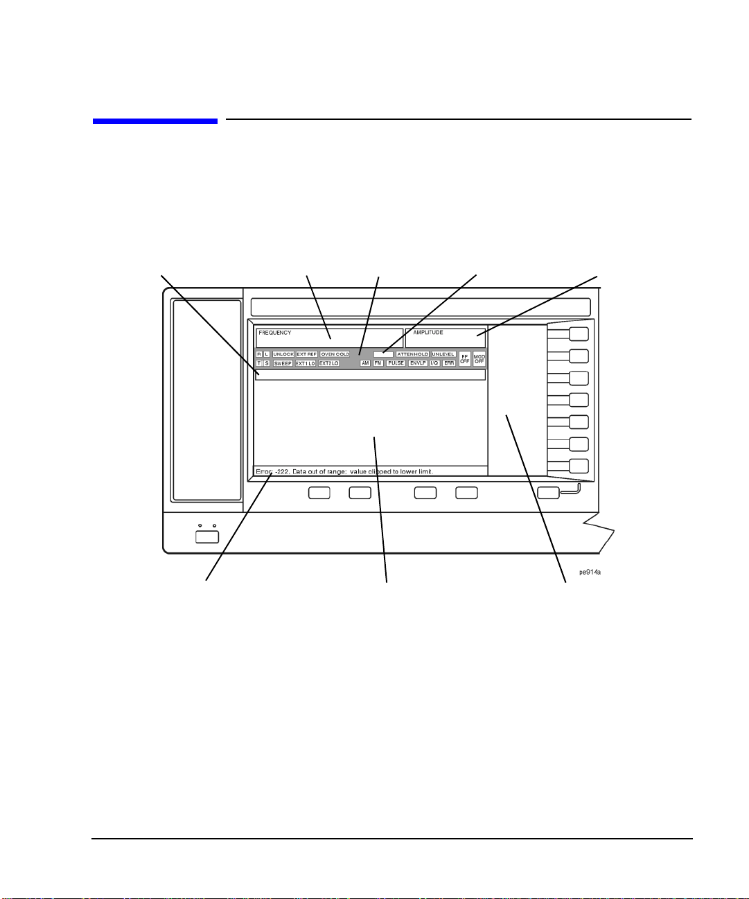
Front Panel Display
Figure 1-2 shows the front panel display. The LCD screen displa ys data fi elds, annotat ions, key pr ess results ,
softkey labels, error messages, and annunciators that represent various active signal generator functions.
Figure 1-2 Front Panel Display Diagram
4. Digital M odulation
1. Active Entry Area
2. Frequency Area
3. Annunciators
Annunciators
5. Amplitude Area
6. Error Message Area
7. Text Area
8. Softkey Label Area
1. Active Entry Area
The current active function is shown in this area. For example, if frequency is the active function, the current
frequency setting will be displayed here. If the current active function has an increment value associated
with it, that value is also displayed.
2. Frequency Area
The current frequency setting is shown in this portion of the display. Indicators are also displayed in this area
when the frequency offset or multiplier is used, the frequency reference mode is turned on, or a source
module is enabled.
Chapter 1 13
Page 24

Signal Generator Overview
Front Panel Display
3. Annunciators
The display annunciators show the status of some of the signal generator functions and indicate any error
conditions. An annunciator position may be used by more than one function. This does not create a problem,
because only one function that shares an annunciator position can be active at a time.
ΦM This annunciator (E8257C and E8267C only) appears when phase modulation is on. If
frequency modulation is on, the FM annunciator replaces ΦM.
ALC OFF This annunciator appears when the ALC circuit is disabled. A second annunciator,
UNLEVEL, appears in the same position if the ALC is enabled and cannot maintain the
output level.
AM This annunciator (E8257C and E8267C only) appears when amplitude modulation is on.
ARMED This annunciator appears when a sweep has been initiated and the signal generator is
waiting for the sweep trigger event.
ATTEN HOLD This annunciator (Option 1E1 or E8267C only) appears when the attenuator hold
function is on. When this function is on, the attenuator is held at its current setting.
DIG BUS This annunciator appears when the Digital Bus is active, and the internal oven reference
oscillator is not cold (they appear in the same location).
ENVLP This annunciator appears if a burst condition exists, such as when marker 2 is set to
enable RF blanking in the Dual ARB format.
ERR This annunciator appears when an error message is in the error queue . This annun ciator
does not turn off until you either view all the error messages or cleared the error queue.
To access error messages, press
Utility > Error Info.
EXT This annunciator appears when external leveling is on.
EXT1 LO/HI This annunciator (E8257C and E8267C only) appears as either EXT1 LO or EXT1 HI,
when the ac-coupled signal to the EXT 1 INPUT is <0.97 V
or >1.03 Vp.
p
EXT2 LO/HI This annunciator (E8257C and E8267C only) is displayed as either EXT2 LO or
EXT2 HI. This annunciator appears when the ac-coupled signal to the EXT 2 INPUT is
<0.97 V
or >1.03 Vp.
p
EXT REF This annunciator appears when an external frequency reference is applied.
FM This annunciator (E8257C and E8267C only) appears when frequency modulation is
turned on. If phase modulation is turned on, the ΦM annunciator will replace FM.
I/Q This annunciator (E8267C with Option 002/602 only) appears when I/Q modulation is
turned on.
L This annunciator appears when the signal generator is in listener mode and is receiving
information or commands over the RS-232, GPIB, or VXI-11 LAN interface.
14 Chapter 1
Page 25

Signal Generator Overview
Front Pane l Display
MOD ON/OFF This annunciator (E8257C and E8267C only) which is always present on the display,
indicates whether active modulation formats have been enabled or disabled with the
Mod On/Off hardkey. Pressing the Mod On/Off hardkey enables or disables all active
modulation formats (AM, FM, ΦM , Pulse, or I/Q) that are applied to the output carrier
signal available through the RF Output connector. The
Mod On/Off hardkey does not set
up or activate an AM, FM, ΦM, Pulse, or I/Q format; each individual modulation
format must still be set up and activated (for example,
applied to the output carrier signal when the
Mod On/Off hardkey is enabled.
AM > AM On) or nothing will be
OVEN COLD This annunciator (Option UN R only) appear s when the temper ature of the internal o ven
reference oscillator has dropped below an acceptable lev el. When this annunciator is on,
frequency accuracy is degraded. This condition should occur only if the signal generator
is disconnected from line power.
PULSE This annunciator (E8257C and E8267C only) appears when pulse modulation is on.
R This annunciator appears when the signal generator is remotely controlled over the
GPIB, RS-232, or VXI-1 1/Sockets LAN inter face (TELNET operation d oes not activate
the R annunciator). When the R annunciator is on, the front panel keys are disabled,
except for the Local key and the line power switch. For information on remote
operation, refer to the Programmi ng Gui de.
RF ON/OFF This annunciator indicates when the RF and microwave signal is present (RF ON) at the
RF OUTPUT, or if the RF and microwave signal is not present (RF OFF) at the RF
OUTPUT. Either condition of this an nunciator is always visible in the display.
S This annunciator appears when the signal generator has generated a service request
(SRQ) over the RS-232, GPIB, or VXI-11 LAN interface.
SWEEP This annunciator appears when the signal generator is in list, step, or ramp sweep mode;
ramp sweep is available with Option 007 only. List mode is when the signal generator
can jump from point to point in a list (hop list); the list is traversed in ascending or
descending order. The list can be a frequency list, a power level list, or both. Step mode
is when a start, stop, and step value (frequency or power level) are defined and the
signal generator produces signals that start at the start value and increment by the step
value until it reaches the stop value. Ramp sweep mode (Option 007 only) is when a
start and st op value (fre quency or po wer level) are defined and the signal generator
produces signals that start at the start value and produce a continuous output until it
reaches the stop value.
T This annunciator appears when the signal generator is in talker mode and is transmitting
information over the GPIB, RS-232, or VXI-11 LAN interface.
UNLEVEL This annunciator appears when the signal generator is unable to maintain the correct
output level. The UNLEVEL annunciator is not necessarily an indication of instrument
failure. Unleveled conditions can occur during normal operation. A second annunciator,
ALC OFF, will appear in the same position when the ALC circuit is disabled.
Chapter 1 15
Page 26

Signal Generator Overview
Front Panel Display
UNLOCK This annunciator appears when any of the phase locked loops are unable to maintain
phase lock. You can determine which loop is unlocked by examining the error
messages.
4. Digital Modulation Annunciators
All digital modulation annunciators (E8267C PSG with Option 002/602 only) appear in this location. These
annunciators appear only when the modulation is active, and only one digital modulation can be active at
any given time.
ARB Dual Arbitrary Waveform Generator M-TONE Multitone Waveform Generator
CUSTOM Custom Real Time I/Q Baseband T-TONE Two-Tone Waveform Generator
DIGMOD Custom Arb Waveform Generator
5. Amplitude Area
The current output power level setti ng is shown in this po rtion of the displ ay. Indicators are also displayed in
this area when amplitude offset is used, amplitude reference mode is turned on, external leveling mode is
enabled, a source module is enabled, and when user flatness is enabled.
6. Error Message Area
Abbreviated error messages are reported in this space. When multiple error messages occur, only the most
recent message remains displayed. Reported error messages with details can be viewed by pressing
Error Info.
Utility >
7. Text Area
This text area of the display:
• show signal generator status information, such as the modulation status, sweep lists, and file catalogs
• displays the tables
• enables you to perfor m functio ns such as man aging inf orm ation, enteri ng info rmation, and dis playin g or
deleting files
8. Softkey Label Area
The labels in this area define the function of the softkeys located immediately to the right of the label. The
softkey label may change depending upon the function selected.
16 Chapter 1
Page 27
Signal Generator Overview
Rear Panel
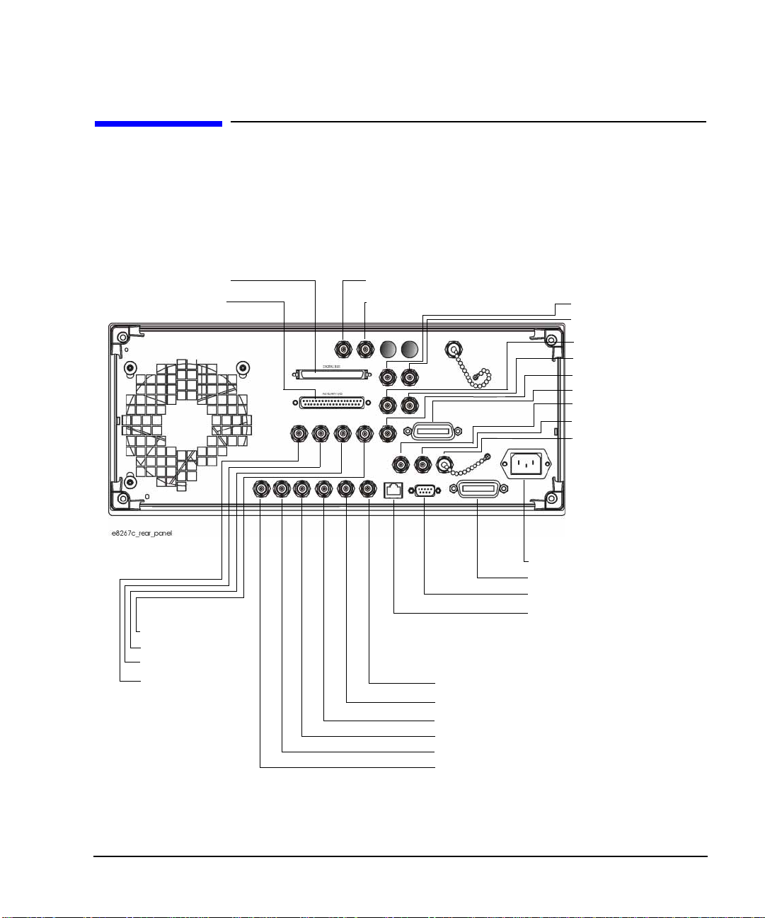
Rear Panel
The signal generator rear panel (Figure 1-3) provides input, output, and remote interface connections.
Descriptions are provided for each rear panel connector. When Option 1EM is added, all front panel
connectors are moved to the real panel; for a description of these connectors, see “Front Panel” on page 6.
Figure 1-3 Rear Panel Diagram
16. Digital Bus
15. AUXILIARY I/O
14. BURST GATE IN
13. PATTERN TRIG
12. EVENT 2
11. EVENT 1
17. WIDEBAND I INPUT
18. WIDEBAND Q INPUT
19. COH
5. STOP SWEEP IN/OUT
6. Z-AXIS BLANK/MKRS
7. SWEEP OUT
8. TRIGGER OUT
9. TRIGGER IN
10. SOURCE SETTLED
20. I OUT
21. I-bar OU T
22. Q OUT
23. Q-bar OUT
24. BASEBAND GEN
25. SMI
26. 10 MHz OUT
27. 10 MHz IN
28. 10 MHz EFC
(Option UNR)
1. AC Power Receptacle
2. GPIB
3. AUXILIARY INTERFACE
4. LAN
Chapter 1 17
Page 28

Signal Generator Overview
Rear Panel
1. AC Power Receptacle
The ac line voltage is connected here. The power cord receptacle accepts a three-pronged power cable that is
shipped with the signal generator.
2. GPIB
This GPIB interface allows listen and talk capability with compatible IEEE 488.2 devices.
3. AUXILIARY INTERFACE
This 9-pin D-subminiature female connector is an RS-232 serial port that can be used for serial
communication and Master/Slave source synchronization.
Table 1-3 Auxiliary Interface Connector
Pin Number Signal Description Signal Name
1 No Connection
2 Receive Data RECV
3 Transmit Data XMIT
4+5V
5 Ground, 0V
6 No Connection
7Request to SendRTS
8 Clear to Send CTS
9 No Connection
Figure 1-4
View looking into
rear panel connector
4. LAN
This LAN interface allows ethernet local area network communication through a 10Base-T LAN cable. The
yellow LED on the interface illuminates when data transmission (transfer/receive) is present. The green
LED illuminates when there is a delay in data transmission or no data transmission is p resent.
18 Chapter 1
Page 29

Signal Generator Overview
Rear Panel
5. STOP SWEEP IN/OUT
This female BNC connector (Option 007 only) provides an open-collector, TTL-compatible input/output
signal that is used during ramp sweep operation. It provides low level (nominally 0V) output during sweep
retrace and band-cross intervals. It provides high level (nominally +5V) outpu t during the forward portion of
sweep. Sweep stops when this input/output connector is grounded externally.
6. Z-AXIS BLANK/MKRS
This female BNC connector (Option 007 only) supplies a +5V (nominal) level during retrace and
band-switch intervals of a step, list, or ramp sweep. During ramp sweep, this female BNC connector
supplies a –5V (nominal) level when the RF frequency is at a marker frequency and intensity marker mode
is on. This connection is most commonly used to interface with an Agilent 8757D scalar network analyzer.
7. SWEEP OUT
This female BNC connector outputs a voltage proportional to the RF power or frequency sweep ranging
from 0 V at the start of sweep and goes to +10V (nominal) at the end of sweep, regardless of sweep width.
The output impedance is less than 1Ω and can drive a 2 kΩ load.
When connected to an Agilent Technologies 8757D network analyzer, it generates a selectable number of
equally spaced 1 ms 10 V pulses (nominal) across a ramp (analog) sweep. The number of pulses can be set
from 101 to 1601 by remote control through the 8757D.
8. TRIGGER OUT
This female BNC connector , in step /list sweep mo de, outp uts a TT L s ignal that is high at the s tart o f a dwell
sequence or when waiting for a point trigger in manual sweep mode. The signal is low when the dwell is
over or when a point trigger is received. In ramp sweep mode, the output p rov ides 1 601 equally-spaced 1 µs
pulses (nominal) across a ramp sweep. When using LF Out, the output provides a 2 µs pulse at the start of
LF sweep.
9. TRIGGER IN
This female BNC connector accepts a 3.3V CMOS signal that is used for point-to-point triggering in manual
sweep mode or a low-frequency (LF) sweep in external sweep mode. Triggering can occur on either the
positive or negative edge of the signal start. The damage level is ≤ −4V or ≥+10 V.
10. SOURCE SETTLED
This female BNC connector provides an indication when the signal generator has s ettled to a new frequency
or power level. A low indicates that the source has settled.
Chapter 1 19
Page 30

Signal Generator Overview
Rear Panel
11. EVENT 1
This female BNC connector (E8267C only) is used with an internal baseband generator (Option 002/602);
on signal generators without Option 002/602, this female BNC connector is non-functional.
In real-time mode, the EVENT 1 connector outputs a pattern or frame synchronization pulse for triggering
or gating external equipment. It may be set to start at the beginning of a pattern, frame, or timeslot and is
adjustable to within ± one timeslot with one bit resolution.
In arbitrary waveform mode, the EVENT 1 connector out puts a timing signal generated by Marker 1.
A marker (3.3V CMOS high when positive polarity is selected; 3.3V CMOS low when negative polarity is
selected) is output on the EVENT 1 connector whenever a Marker 1 is turned on in the waveform. The
damage levels for this connector are > +8V and < −4V.
12. EVENT 2
This female BNC connector (E8267C only) is used with an internal baseband generator (Option 002/602);
on signal generators without Option 002/602, this female BNC connector is non-functional. In real-time
mode, the EVENT 2 connector outputs a d ata enable signal fo r gating external eq uipment. Th is is applicable
when external data is clocked into internally generated timeslots.
Data is enabled when the signal is low. In arbitrary waveform mode, the EVENT 2 connector outputs a
timing signal generated by Marker 2. A marker (3.3V CMOS high when positive polarity is selected; 3.3V
CMOS low when negative polarity is selected) is output on the EVENT 2 connector whenever a Marker 2 is
turned on in the waveform. The damage levels for this connector are > +8V and < −4V.
13. PATTERN TRIG IN
This female BNC connector (E8267C only) is used with an internal baseband generator (Option 002/602);
on signal generators without Option 002/602, this female BNC connector is non-functional. This connector
accepts a signal that triggers an internal pattern or frame generator to start single pattern output. Minimum
pulse width is 100 ns. Damage levels are > +5.5 and < −0.5V.
14. BURST GATE IN
This female BNC connector (E8267C only) is used with an internal baseband generator (Option 002/602);
on signal generators without Option 002/602, this female BNC connector is non-functional. This connector
accepts a signal for gating burst power. Burst gating is used when you are externally supplying data and
clock information.
The input signal must be synchronized with the external data input that will be output during the burst. The
burst power envelope and mo dul ated dat a are internally delayed and re-synchronized. The input signal must
be CMOS high for normal burst RF power or CW RF output power and CMOS low for RF off. Damage
levels are > +5.5 and < −0.5V.
20 Chapter 1
Page 31

Signal Generator Overview
al
put
ut
n
r to
S
.
pin
.
Rear Panel
15. AUXILIARY I/O
This female 37-pin connector (E8267C only) is active only on instruments with an internal baseband
generator (Option 002/602); on signal generators without Option 002/602, this connector is non-functional.
This connector provides access to the inputs and outputs described in the following figure.
Figure 1-5 Auxiliary I/O Connector (Female 37-Pin)
View looking into
rear panel connector
Used with an internal baseband generator. In arbitrary waveform mode, this pin outp
a timing signal generated by Marker 3. A marker (3.3V CMOS high when positive
polarity is selected; 3.3V CMOS low when negative polarity is selected) is output o
this pin when a Marker 3 is turned on in the waveform.
Reverse damage levels: > +8V and < −4V.
Used with an internal baseband generator. In arbitrary waveform mode, this
outputs a timing signal generated by Marker 4. A marker (3.3V CMOS high
when positive polarity is selected; 3.3V CMOS low when negative polarity is
selected) is output on this pin when a Marker 4 is turned on in the waveform
Reverse damage levels: > +8V and < −4V.
Accepts a signal that triggers an internal pattern or frame generato
start single pattern output. Minimum pulse width: 100 ns.
Damage levels: > +5.5 and < −0.5V
Used with an internal baseband generator. This pi n accepts a CMOS sign
for synchronization of external data and alternate power signal timing.
Damage levels are > +8V and < −4V.
Used with an internal baseband generator. This pin outputs data (CMOS)
from the internal data generator or the externally supplied signal at data in
Used with an internal baseband generator. This pin relays a
CMOS bit clock signal for synchronizing serial data.
Used with an internal baseband generator. This pin outputs the CMO
symbol clock for symbol synchronizat ion, one data clock period wide
Chapter 1 21
Page 32

Signal Generator Overview
Rear Panel
16. Digital Bus
This is a proprietary bus used for Agilent Baseband Studio products, which require an E8267C with Option
602. This connector is not operational for general purpose customer use. Signals are present only when a
Baseband Studio option is installed (for details, refer to www.agilent.com/find/basebandstudio). The
Dig Bus annunciator appears on the display when the Digital Bus is active (and the internal oven reference
oscillator is not cold—they appear in the same location).
17. WIDEBAND I INPUT
This female BNC connector (E8267C only) is used with wideband external I/Q inputs (Option 015). It
accepts wide-band AM and allows direct high-bandwidth analog inputs to the I/Q modulator in the
3.2−20 GHz range. This input is not calibrated and accepts a 0 dBm maximum power. On signal generators
without Option 015, this connector is non-functional.
18. WIDEBAND Q INPUT
This female BNC connector (E8267C only) is used with wideband external I/Q inputs (Option 015); on
signal generators without Option 015, this female BNC connector is non-functional. This female BNC
connector allows direct high-bandwidth analog inputs to the I/Q modulator in the 3.2 to 20 GHz frequency
range. This input is not calibrated and accepts a 0 dBm maximum power.
19. COH (COHERENT CARRIER OUTPUT)
This female SMA connector (E8267C only) outputs an RF signal that is phase coherent with the signal
generator carrier. The coherent carrier connector outputs RF that is not modulated with AM, pulse, or I/Q
modulation, but is modulated with FM or ΦM (when FM or ΦM are on).
The output power is nom in ally 0 dB m. T he o ut pu t freq uency range is from 249.99900001 MHz to 3.2 GHz;
this output is not useful for output frequencies > 3.2 GHz. If the RF output frequency is below
249.99900001 MHz, the coherent carrier output signal will have the following frequency:
• Frequency of coherent carrier = (1E9 − Frequency of RF output) in Hz.
• Damage levels are 20 Vdc and 13 dBm reverse RF power.
20. I OUT
This female BNC connector (E8267C only) can be used with an internal baseband generator (Option
002/602) to output the analog, in-phase component of I/Q modulation; on signal generators without Option
002/602, this female BNC connector can be used to output the in-phase component of an external I/Q
modulation that has been fed into the I input connector. The nominal output impedance of the I OUT
connector is 50Ω, dc-coupled.
22 Chapter 1
Page 33

Signal Generator Overview
Rear Panel
21. I-bar OUT
This female BNC connector (E8267C only) can be used with an internal baseband generator (Option
002/602) to output the complement of the analog, in-phase component of I/Q modulation; on signal
generators without Op tion 0 02/6 02, thi s female BNC connect or can b e used to ou tput the com plement of th e
in-phase component of an external I/Q modulation that has been fed into the I input connector.
I-bar OUT is used in conjunction wi th I OUT to provide a balanced baseband stimulus. Balanced signals are
signals present in two separate conductors that are symmetrical relative to ground and are opposite in
polarity (180 degrees out of phase). The nominal output impedance of the I-bar OUT connector is 50Ω,
dc-coupled.
22. Q OUT
This female BNC connector (E8267C only) can be used with an internal baseband generator (Option
002/602) to output th e analog, qu adratur e-pha se compo nent of I/ Q modul ation; on sign al gener ators with out
Option 002/602, this female BNC connector can be used to output the quadrature-phase component of an
external I/Q modulation that has been fed into the Q input connector. The nominal output impedance of the
Q OUT connector is 50Ω, dc-coupled.
23. Q-bar OUT
This female BNC connector (E8267C only) can be used with an internal baseband generator (Option
002/602) to output the com plement o f the analo g, quadratu re-phas e componen t of I/Q mo dulation ; on signal
generators without Op tion 0 02/6 02, thi s female BNC connect or can b e used to ou tput the com plement of th e
quadrature-phase component of an external I/Q modulation that has been fed into the Q input connector.
Q-bar OUT is used in conjunction with Q OUT to provide a balanced baseband stimulus. Balanced signals
are signals present in two separate conductors that are symmetrical relative to ground and are opposite in
polarity (180 degrees out of phase). The nominal output impedance of the Q-bar OUT connector is 50Ω,
dc-coupled.
24. BASEBAND GEN REF IN
This female BNC connector (E8267C only) is used with an internal baseband generator (Option 002/602);
on signal generators without Option 002/602, this female BNC connector is non-functional. This connector
accepts a 0 to +20 dBm sine wave or TTL square wave signal from an external timebase reference. This
external timebase reference clock is used by the internal baseband generator for both component and
receiver test applications (only the internal baseband generator can be locked to this external reference; the
RF frequency remains locked to the 10 MHz reference).
This connector accepts rates from 250 kHz through 100 MHz; the nominal input impedance is 50Ω. at
13 MHz, ac-coupled. The internal clock for the arbitrary waveform generator is locked to this signal when
external reference is selected in the ARB setup. The minimum pulse width must be > 10 ns. The damage
levels are > +8V and < −8V.
Chapter 1 23
Page 34

Signal Generator Overview
Rear Panel
25. SMI (SOURCE MODULE INTERFACE)
This interface is used to connect to compatible Agilent Technologies 83550 Series mm-wave source
modules.
26. 10 MHz OUT
This female BNC connector outputs a nominal signal level of > +4 dBm and has an output impedance of
50Ω. The accuracy is determined by the timebase used.
27. 10 MHz IN
This female BNC connector accepts an external timebase reference input signal level of >−3dBm. The
reference must be 1, 2, 2.5, 5, or 10 MHz, within ±1 ppm. The signal generator detects when a valid
reference signal is present at this connector and automatically switch e s f r om internal to external reference
operation. The nominal input impedance is 50Ω. For Option UNR, this BNC connector accepts a signal with
a nominal input level of 5 ±5 dBm. The external frequency reference must be 10 MHz, within ±1 ppm. The
nominal input impedance is 50Ω with a damage level of ≥ 10 dBm.
28. 10 MHz EFC (Option UNR)
This female BNC input connector accepts an external dc voltage, ranging from −5 to +5V, for electronic
frequency control (EFC) of the internal 10 MHz reference oscillator. This voltage inversely tunes the
oscillator about its center frequency approximately −0.0025 ppm/V. The input resistance is greater than
1MΩ. When not in use, this connector should be shorted using the supplied shorting cap to assure a stable
operating frequency.
24 Chapter 1
Page 35

2 Basic Operation
In the following sections, this chapter describes operations common to all Agilent PSG signal generators:
• “Using Table Editors” on page 26
• “Configuring a Continuous Wave RF Output” on page 28
• “Configuring a Swept RF Output” on page 31
• “Using Ramp Sweep (Option 007)” on page 37
• “Extending the Frequency Range with a mm-Wave Source Module” on page 47
• “Turning On a Modulation Format” on page 50
• “Applying a Modulation Format to the RF Output” on page 51
• “Using Data Storage Functions” on page 52
• “Enabling Options” on page 57
25
Page 36

Basic Operation
Using Table Editors
Using Table Editors
T able editors simplify configur ation tasks, such as creating a list sweep. Th is section provides information to
familiarize you with basic table editor functionality using the List Mode Values table editor as an example.
Press
Preset > Sweep/List > Configure List Sweep.
The signal generator displays the List Mode Values table editor, as shown below.
Figure 2-1
Active Function Area
Table Name
Tabl e Items
Cursor
Table Softkeys
Active Function Area displays the acti ve table item while its value is edited
Cursor an inverse video identifier used to highlight specific table items for
selection and editing
Table Softkeys select table items, preset table values, and modify table structures
T able Items values arranged in numbered rows and titled columns (The columns
are also known as data fields. For example, the column below the
Frequency title is known as the Frequency data field).
26 Chapter 2
Page 37

Basic Operation
Using Table Editors
Table Editor Softkeys
The following table editor softkeys are used to load, navigate, modify, and store table item values.
Edit Item displays the selected item in the active function area of the display where the item’s
value can be modified
Insert Row inserts an identical row of table items above the currently selected row
Delete Row deletes the currently selected row
Goto Row opens a menu of softkeys (Enter, Goto T op Row, Goto M iddle Row, Goto Bottom Row, Page Up,
and
Page Down) used to quickly navigate through the table items
Insert Item inserts an identical item in a new row below the currently selected item
Delete Item deletes the item from the bottom row of the currently selected column
Page Up and
Page Down displays table items that occupy rows outside the limits of the ten-row table display area
More (1 of 2) accesses Load/Store and its associated softkeys
Load/Store opens a menu of softkeys (Load From Selected File, Store To File, Delete File, Goto Row, Page
Up
, and Page Dow n) used to load table items from a file in the memory catalog, or to
store the current table items as a file in the memory catalog
Modifying Table Items in the Data Fields
1. If not already displayed, open the List Mode Values table editor (shown in Figure 2-1 on page 26):
Press
Preset > Sweep/List > Configure List Sweep
2. Use the arrow keys or the knob to move the table cursor over the desired item.
In Figure 2-1, the first item in the Frequency data field is selected.
3. Press
4. Use the knob, arrow keys, or the numeric keypad to modify the value.
5. Press
Chapter 2 27
Edit Item.
The selected item is displayed in the active function area of the display.
Enter.
The modified item is now displayed in the table.
Page 38

Basic Operation
Configuring the RF Output
Configuring the RF Output
This section provides information on how to create continuous wave and swept RF (on page 31) outputs. It
also has information on using a mm-Wave source module to extend the signal generator’s frequency range
(see page 47).
Configuring a Continuous Wave RF Output
These procedures demonstrate how to set the following parameters:
• RF output frequency
• frequency reference and frequency offset (on page 29)
• RF output amplitude (on page 30)
• amplitude reference and amplitude of fs et (page 30)
Setting the RF Output Frequency
Set the RF output frequency to 700 MHz, and increment or decrement the output frequency in 1 MHz steps.
1. Return the signal generator to the factory-defined state: Press
NOTE You can change the preset condition of the signal generator to a user-defined state. For these
examples, however, use the factory-defined preset state (set the
in the Utility menu to Normal).
2. Observe the FREQUEN CY area of the display (in the upper left-hand corner).
The value displayed is the maximum specified frequency of the signal generator.
3. Press
4. Press
5. Press
RF On/Off.
The
RF On/Off hardkey must be pressed before the RF signal is available at the
RF OUTPUT connector. The display annunciator changes from RF OFF to RF ON. The maximum
specified frequency should be output at the RF OUTPUT connector (at the signal generator’s minimum
power level).
Frequency > 700 > MHz.
The 700 MHz RF frequency should be displayed in the FREQUENCY area of the display and also in the
active entry area.
Frequency > Incr Set > 1 > MHz.
This changes the frequency increment value to 1 MHz.
Preset.
Preset Normal User softkey
28 Chapter 2
Page 39

6. Press the up arrow key.
Basic Operation
Configuring the RF Output
Each press of the up arrow key increases the frequency by the increment value last set with the
Incr Set
hardkey. The increment value is displayed in the active entry area.
7. The down arrow decreases the frequency by the increment value set in the previous step. Practice
stepping the frequency up and down in 1 MHz increments.
You can also adjust the RF output frequency using the knob. As long as frequency is the active function
(the frequency is displayed in the active entry area), the knob will increase and decrease the RF output
frequency.
8. Use the knob to adjust the frequency back to 700 MHz.
Setting the Frequency Reference and Frequency Offset
The following procedure set s the RF o utput freq uency as a reference frequency to which all other frequency
parameters are relative. The frequency initially shown on the display is 0.00 Hz (the frequency output by
the hardware minus the reference frequency). Although the display changes, the frequency output does not
change. Any subsequent frequency changes are shown as incremental or decremental to 0 Hz.
1. Preset the signal generator: Press:
Preset
2. Set the frequency reference to 700 MHz:
Press:
Frequency > 700 > MHz > More (1 of 3) > Freq Ref Set.
This activates the frequency reference mode and sets the current output frequency (700 MHz) as the
reference value. The FREQUENCY area displays 0.000 Hz, which is the frequency output by the
hardware (700 MHz) minus the reference value (700 MHz). The REF indicator activates and the
Freq Ref Off On softkey toggles to On.
3. Turn on the RF output: Press
RF On/Off.
The display annunciator changes from RF OFF to RF ON. The RF frequency at the RF OUTPUT
connector is 700 MHz.
4. Set the frequency increment value to 1 MHz: Press
Frequency > Incr Set > 1 > MHz.
5. Increment the output frequency by 1 MHz: Press the up arrow key.
The FREQUENCY area display changes to show 1.000 000 000 MHz, which is the frequency output by
the hardware (700 MHz + 1 MHz) minus the reference frequency (700 MHz). The frequency at the RF
OUTPUT changes to 701 MHz.
6. Enter a 1 MHz offset: Press
More (1 of 3) > Freq Offset > 1 > MHz.
The FREQUENCY area displays 2. 000 00 0 00 MHz, which is the frequency output by the hardware
(701 MHz) minus the reference frequency (700 MHz) plus the offset (1 MHz). The OFFS indicat or
activates. The frequency at the RF OUTPUT connector is still 701 MHz.
Chapter 2 29
Page 40

Basic Operation
Configuring the RF Output
Setting the RF Output Amplitude
1. Preset the signal generator: Press
Preset.
The AMPLITUDE area of the display shows the minimum power level of the signal generator. This is the
normal preset RF output amplitude.
2. Turn on the RF output: Press
RF On/Off.
The display annunciator ch anges to RF ON. At the RF OUTPUT connector, the RF signal is output at the
minimum po wer level.
3. Change the amplitude to −20 dBm: Press
Amplitude > −20 > dBm.
The new output power displays in the AMPLITUDE area of the display and in the active entry area. Until
you press a different front panel function key, amplitude remains the active function. You can also
change the amplitude using the up and down arrow keys or the knob.
Setting the Amplitude Reference and Amplitude Offset
The following procedure sets the RF output power as an amplitude reference to which all other am plit ude
parameters are relative. The amplitude initially shown on the display is 0 dB (the power output by the
hardware minus the reference power). A lthough the dis play changes, the o utput power do es not chang e. A ny
subsequent power changes are shown as incremental or decremental to 0 dB.
1. Press
2. Set the amplitude to −20 dBm: Press
Preset.
Amplitude > -20 > dBm.
3. Activate the amplitude reference mode and set the current output power (−20 dBm) as the reference
value: Press
More (1 of 2) > Ampl Ref Set.
The AMPLITUDE area displays 0. 00 dB, which is the power output by the hardware (−20 dBm) minus
the reference value (−20 dBm). The REF indicator activates and the
4. Turn the RF output on: Press
RF On/Off.
Ampl Ref Off On softkey toggles On.
The display annunciator changes to RF ON. The power at the RF OUTPUT connector is −20 dBm.
5. Change the amplitude increment value to 10 dB: Press
Incr Set > 10 > dB.
6. Use the up arrow key to increase the output power by 10 dB.
The AMPLITUDE area displays 10 .00 dB, which is the power output by the hardware
(-20 dBm plus 10 dBm) minus the reference power (−20 dBm). The power at the RF OUTPUT
connector changes to −10 dBm.
7. Enter a 10 dB offset: Press
Ampl Offset > 10 > dB.
The AMPLITUDE area displays 20.00 dB, which is the pow er output by t he hardware (−10 dBm) minu s
the reference power (−20 dBm) plus the offset (10 dB). The OFFS indicator activates. The power at the
RF OUTPUT connector is still −10 dBm.
30 Chapter 2
Page 41

Basic Operation
Configuring the RF Output
Configuring a Swept RF Output
A PSG signal generator has up to three sweep types: step sweep, list sweep, and ramp sweep (Option 007).
NOTE List sweep data cannot be saved within an instrument state, but can be saved to the memory
catalog. For instructions on saving list sweep data, see “Storing Files to the Memory
Catalog” on page 53.
During swept RF output, the FREQUENCY and AMPLITUDE areas of the signal generator’s
display are deactivated, depending on what is being swept.
Step sweep (see page 32) and ramp sweep (see page 34) provide a linear progression through the
start-to-stop frequency and/or amplitude values, while list sweep enables you to create a list of arbitrary
frequency, amplitude, and dwell time values and sweep the RF output based on that list.
The list sweep example uses the points created in the step sweep example as the basis for a new list sweep.
Ramp sweep (see page 37) is faster than step or list sweep, and is designed to work with an 8757D scalar
network analyzer.
Chapter 2 31
Page 42

Basic Operation
Configuring the RF Output
Using Step Sweep
Step sweep provides a linear progression through the start-to-stop frequency and/or amplitude values. You
can toggle the direction of the sweep, up or down. When the
Sweep Direction Down Up softkey is set to Up,
values are swept from the start amplitude/frequency to the stop amplitude/frequency. When set to Down,
values are swept from the stop amplitude/frequency to the start amplitude/frequency.
When a step sweep is activated, the signal generator sweeps the RF output based on the values entered for
RF output start and stop frequencies and amplitudes, a number of equally spaced points (steps) to dwell
upon, and the amount of dwell time at each point; dwell time is the minimum period of time after the settling
time that the signal generator will remain at its current state. The frequency, amplitude, or frequency and
amplitude of the RF output will sweep from the start amplitude/frequency to the stop amplitude/frequency,
dwelling at equally spaced intervals defined by the
# Points softkey valu e.
To Configure a Single Step Sweep
In this procedure, you create a step sweep with nine, equally-spaced points, and the following parameters:
• frequency range from 500 MHz to 600 MHz
• amplitude from −20 dBm to 0 dBm
• dwell time 500 ms at each point
1. Press
2. Press
Preset.
Sweep/List.
This opens a menu of sweep softkeys.
3. Press
Sweep Repeat Sing le Cont.
This toggles the sweep repeat from continuous to single.
4. Press
ConfigureStep Sweep.
5. Press Freq Start > 500 > MHz.
This changes the start frequency of the step sweep to 500 MHz.
6. Press
Freq Stop > 600 > MHz.
This changes the stop frequency of the step sweep to 600 MHz.
7. Press
Ampl Start > -20 > dBm.
This changes the amplitude level for the start of the step sweep.
8. Press
Ampl Stop > 0 > dBm.
This changes the amplitude level for the end of the step sweep.
9. Press
# Points > 9 > Enter.
This sets the number of sweep points to nine.
10. Press
Step Dwell > 500 > msec.
This sets the dwell time at each point to 500 milliseconds.
32 Chapter 2
Page 43

Basic Operation
Configuring the RF Output
11. Press Return > Sweep > Freq & Ampl.
This sets the step sweep to sweep both frequency and amplitude data. Selecting this softkey returns you
to the previous menu and turns on the sweep function.
12. Press
RF On/Off.
The display annunciator changes from RF OFF to RF ON.
13. Press
Single Sweep.
A single sweep of the frequencies and amplitudes configured in the step sweep is executed and available
at the RF OUTPUT connector. On the display, the SWEEP annunciator appears for the duration of the
sweep and a progress b ar s ho ws the progression of the sweep. The
Single Sweep softkey can also be used
to abort a sweep in progress. To see the frequencies sweep again, press Single Sweep to trigger the
sweep.
To Configure a Continuous Step Sweep
Press
Sweep Repeat Single Cont.
This toggles the sweep from single to continuous. A continuous repetition of the frequencies and amplitudes
configured in the step sweep are now available at the RF OUTPUT connector. The SWEEP annunciator
appears on the display, indicating that the signal generator is sweeping and progression of the sweep is
shown by a progress bar.
Chapter 2 33
Page 44

Basic Operation
Configuring the RF Output
Using List Sweep
List sweep enables you to create a list of arbitrary frequency, amplitude, and dwell time values and sweep
the RF output based on the entries in the List Mode Values table.
Unlike a step sweep that contains linear ascending/descending frequ ency and amplitude values , spaced at
equal intervals throughout the sweep, list sweep frequencies and amplitudes can be entered at unequal
intervals, nonlinear ascending/descending, or random order.
For convenience, the List Mode Values table can be copied from a previously configured step sweep. Each
step sweep point’s associated frequency, amplitude and dwell time values are entered into a row in the List
Mode Values table, as the following example illustrates.
To Configure a Single List Sweep Using Step Sweep Data
In this procedure, you will leverage the step sweep points and change the sweep information by editing
several points in the List Mode Values table. For information on using tables, see “Using Table Editors” on
page 26.
1. Press
Sweep Repeat Single Cont.
This toggles the sweep repeat from continuous to single. The SWEEP annunciator is turned off. The
sweep will not occur until it is triggered.
2. Press
Sweep T ypeList Step.
This toggles the sweep type from step to list.
3. Press
Configure List Sweep.
This opens another menu displaying softkeys that you will use to create the sweep points. The display
shows the current list data. (When no list has been previously created, the default list contains one point
set to the signal generator’s maximum frequency, minimum amplitude, and a dwell time of 2 ms.)
4. Press
More (1 of 2) > Load List From Step Sweep > Confirm Load From Step Data.
The points you defined in the step sweep are automatically loaded into the list.
34 Chapter 2
Page 45

To Edit Lis t Sw eep Points
Basic Operation
Configuring the RF Output
1. Press
Return > Sweep > Off.
Turning the sweep off allows you to edit the list sweep points without generating errors. If sweep
remains on during editing, errors occur whenever one or two point parameters (frequency, power, and
dwell) are undefined.
2. Press
Configure List Sweep.
This returns you to the sweep list table.
3. Use the arrow keys to highlight the dwell time in row 1.
4. Press
Edit Item.
The dwell time for point 1 becomes the active function.
5. Press
100 > msec.
This enters 100 ms as the new dwell time value for row 1. Note that the next item in the table (in this
case, the frequency value for point 2) becomes highlighted after you press the terminator softkey.
6. Using the arrow keys, highlight the frequency value in row 4.
7. Press
Edit Item > 545 > MHz.
This changes the frequency value in row 4 to 545 MHz.
8. Highlight any column in the point 7 row and press
Insert Row.
This adds a new point between points 7 and 8. A copy of the point 7 row is placed between points 7 and
8, creating a new point 8, and renumbering the successive points.
9. Highlight the frequency item for point 8, then press
Pressing
Insert Item shifts frequency values down one row, beginning at point 8. Note that the original
Insert Item.
frequency values for both points 8 and 9 shift down one row, creating an entry for point 10 that contains
only a frequency value (the power and dwell time items do not shift down).
The frequency for point 8 is still active.
10. Press
11. Press
590 > MHz.
Insert Item > -2.5 > dBm.
This inserts a new power valu e at point 8 and shif ts down the o riginal p ower v alues for p oints 8 and 9 b y
one row.
12. Highlight the dwell time for point 9, then press
Insert Item.
A duplicate of the highlighted dwell time is inserted for point 9, shifting the existing value down to
complete the entry for point 10.
Chapter 2 35
Page 46

Basic Operation
Configuring the RF Output
To Configure a Single List Sweep
1. Press
Return > Sweep > Freq & Amp l
This turns the sweep on again. No errors should occur if all parameters for every point have been defined
in the previous editing process.
2. Press
Single Sweep.
The signal generator will single sweep the points in your list. The SWEEP annunciator activates during
the sweep.
3. Press
4. Press
More (1 of 2) > Sweep Trigger > Trigger Key.
This sets the sweep trigger to occur when you press the
More (2 of 2) > Single Sweep.
Trigger hardkey.
This arms the sweep. The ARMED annunciator is activated.
5. Press the
Trigger hardkey.
The signal generator will single sweep the points in your list and the SWEEP annunciator will be
activated during the sweep.
To Configure a Continuous List Sweep
Press
Sweep Repeat Single Cont.
This toggles the sweep from single to continuous. A continuous repetition of the frequencies and amplitudes
configured in the list sweep are now available at the RF OUTPUT connector. The SWEEP annunciator
appears on the display, indicating that the signal generator is sweeping and progression of the sweep is
shown by a progress bar.
36 Chapter 2
Page 47

Basic Operation
Configuring the RF Output
Using Ramp Sweep (Option 007)
Ramp sweep provides a linear progression through the start-to-stop frequency and/or amplitude values.
Ramp sweep is much faster than step or list sweep, and is designed to work with an 8757D scalar network
analyzer. This section describ es the ramp sweep capab ilities available in PSG signal generators with Option
007. You will learn how to use basic ramp sweep, and how to configure a ramp sweep for a master/slave
setup (see page 45).
Refer to the Programming Guide for an example program that uses pass-thru commands in a ramp sweep
system (pass-thru commands enable you to temp orar ily interrupt ramp sweep system interaction so that you
can send operating instructions to the PSG).
Using Basic Ramp Sweep Functions
This procedure demonstrates the following tasks (each task builds on the previous task):
• “Configuring a Frequency Sweep” on page 38
• “Using Markers” on page 40
• “Adjusting Sweep Time” on page 42
• “Using Alternate Sweep” on page 43
• “Configuring an Amplitude Sweep” on page 44
Chapter 2 37
Page 48
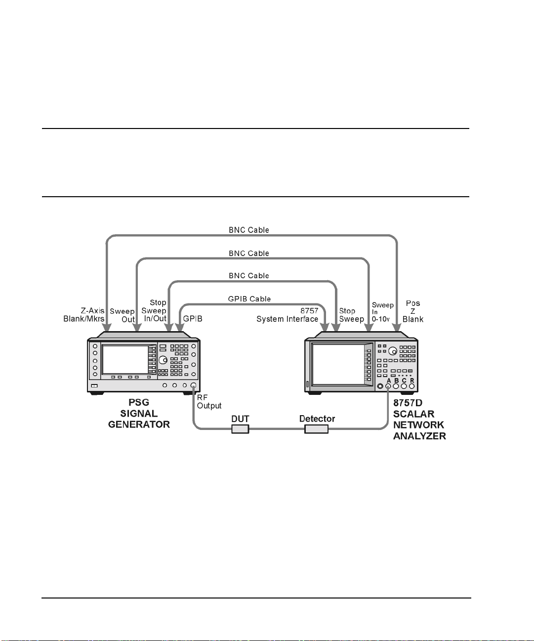
Basic Operation
Configuring the RF Output
Configuring a Frequency Sweep
1. Set up the equipment as shown in Figure 2-2.
NOTE The PSG signal generator is not compatible with the GPIB system interface of an 8757A,
8757C, or 8757E. For these older scalar network analyzers, do not connect the GPIB
cable in Figure 2-2. This method provides only a subset of 8757D functionality. See the
PSG Data Sheet for details. Use the 8757A/C/E documentation instead of this
procedure.
Figure 2-2 Equipment Setup
2. Turn on both the 8757D and the PSG.
3. On the 8757D, press
SYSTEM > MORE > SWEEP MODE and verify that the SYSINTF softkey is set to ON.
This ensures that the system interface mode is activated on the 8757D. The system interface mode
enables the instruments to work as a system.
4. Press
5. On the 8757D, press
Utility > GPIB/RS-232 LAN to view the PSG’s GPIB address under the GPIB Address softkey. If you
want to change it, press
GPIB Address and change the value.
LOCAL > SWEEPER and check the GPIB addr ess. If it does not match that of the PSG,
change the value.
38 Chapter 2
Page 49

Basic Operation
Configuring the RF Output
6. Preset either instrument.
Presetting one of the instruments should automatically preset the other as well. If both instru ments do
not preset, check the GPIB connection, GPIB addresses, and ensure the 8757D is set to system interface
mode (
SYSINTF set to ON).
The PSG automatically activates a 2 GHz to maximum frequency ra mp sweep wi th a cons tant amp litude
of 0 dBm. Notice that the RF ON, SWEEP, and PU LSE annunciators appear on the PSG display. The
PULSE annunciator appears because the 8757D is operating in AC mode.
The PSG also switches its remote language setting to 8757D System, allowing the PSG to talk to the
8757D during ramp sweep operations. You can confirm this by pressing
observing the selection under the
Remote Language softkey.
Utility > GPIB/RS-232 LAN and
NOTE During swept RF output, the FREQUENCY and/or AMPLITUDE areas of the signal
generator’s display are deactivated, depending on what is being swept. In this case,
since frequency is being swept, nothing appears in the FREQUENCY area of the display.
7. Press
Frequency > Freq C W.
The current continuous wave fr equency setting now co ntrols the RF output and r amp sweep i s tur ned off.
8. Press
Freq Start.
The ramp sweep settings once again control the RF output and the CW mode is turned off. Pressing any
one of the softkeys
Freq Start, Freq Stop, Freq Center, or Freq Span activates a ramp sweep with the current
settings.
NOTE In a frequency ramp sweep, the start frequency must be lower than the stop frequency.
9. Adjust the settings for
Freq Center and Freq Span so that the frequency response of the device under test
(DUT) is clearly seen on the 8757D display.
Notice how adjusting these settings also changes the settings for the
Freq Start and FreqStop softkeys. Y ou
may need to rescale the response on the 8757D for a more accurate evaluation of the amplitude. Figure
2-3 on page 40 shows an example of a bandpass filter response.
Chapter 2 39
Page 50

Basic Operation
Configuring the RF Output
Figure 2-3 Bandpass Filter Response on 8757D
Using Markers
1. Press
Markers.
This opens a table editor and associated marker contro l soft keys. You can use up to 10 different markers,
labeled 0 through 9.
2. Press
Marker Freq and select a frequency value within the range of your sweep.
In the table editor, notice how the state for marker 0 automatically turns on. The marker also appears on
the 8757D display.
3. Use the arrow keys to move the cursor in the table editor to marker 1 an d select a frequ ency value within
the range of your sweep, but different from marker 0.
Notice that marker 1 is activated and is the currently selected marker, indicated by the marker arrow
pointing down. As you switch between markers, using the arrow keys, you will notice that the selected
marker’s arrow points down, while all others point up.
Notice also that the frequency and amplitude data for the currently selected marker is displayed on the
8757D.
40 Chapter 2
Page 51

Basic Operation
Configuring the RF Output
4. Move the cursor back to marker 0 and press Delta Ref Set > Marker Delta Off On to On.
In the table editor, notice that the frequency values for each marker are now relative to marker 0. Re f
appears in the far right column (also labeled Ref) to indicate which marker is the reference. Refer to
Figure 2-4.
Figure 2-4 Marker Table Editor
5. Move the cursor back to marker 1 and press
Marker Freq. Turn the front panel knob while observing
marker 1 on the 8757D.
On the 8757D, notice that the displayed amplitude and frequency values for marker 1 are relative to
marker 0 as the marker moves along the trace. Refer to Figure 2-5.
Chapter 2 41
Page 52

Basic Operation
Configuring the RF Output
Figure 2-5 Delta Markers on 8757D
6. Press
Turn Off Markers.
All active markers turn off. Refer to the Key Reference for information on other marker softkey
functions.
Adjusting Sweep Time
1. Press
Sweep/List.
This opens a menu of sweep control softkeys and displays a status screen summarizing all the current
sweep settings.
2. Press
Configure Ramp/Step Sweep.
Since ramp is the current sweep type, softkeys in this menu specifically control ramp sweep settings.
When step is the selected sweep type, the softkeys control step sweep settings. Notice that the
and
Freq Stop softkeys appear in this menu in addition to the Frequency hardkey menu.
Freq Start
42 Chapter 2
Page 53

Basic Operation
Configuring the RF Output
3. Press Sweep Time to Manual > 5 > sec.
In auto mode, the sweep time automatically sets to the fastest allowable value. In manual mode, you can
select any sweep time slower than the fastest allowable. The fastest allowable sweep time is dependent
on the number of trace points and channels being used on the 8757D and the frequency span.
4. Press
Sweep Time to Auto.
The sweep time returns to its fastest allowable setting.
Using Alternate Sweep
1. Press the
This opens the table editor and softkey menu for saving instrument states. Notice that the
Save hardkey.
Select Reg
softkey is active. (For more i n formation on saving instrument states refer t o “Using the In stru ment State
Register” on page 54.)
2. Turn the front panel knob until you find an available register and press
register number. If no registers are available, you can write over an in-use register, by pressing
SAVE. Remember this saved
Re-SAVE.
NOTE When you are using the PSG in a system with an 8757 ne twork anal y zer, you are limited to
using regist ers 1 through 9 in sequence 0 for saving and recalling states.
3. Press
Sweep/List > Configure R amp /Step Swee p and en ter new start and stop frequency values for th e ramp
sweep.
4. Press
Alternate Sweep Register and turn the front panel knob to select the register number of the
previously saved sweep state.
5. Press
Alternate Sweep Off On to On.
The signal generator alternates between the original saved sweep and the current sweep. You may need
to adjust 8757D settings to effectively view both sweeps, such as setting channel 2 to measure sensor A.
Refer to Figure 2-6.
Chapter 2 43
Page 54

Basic Operation
Configuring the RF Output
Figure 2-6 Alternating Sweeps on 8757D
Configuring an Amplitude Sweep
1. Press
Return > Sweep > Off.
This turns off both the current sweep and the alternate sweep from the previous task. The current CW
settings now control the RF output.
2. Press
3. Using the
4. Press
Configure Ramp/Step Sweep.
Ampl Start and Ampl Stop softkeys, set an amplitude range to be swept.
Return > Sweep > Ampl.
The new amplitude ramp sweep settings control the RF output and the CW mode is turned off.
44 Chapter 2
Page 55

Basic Operation
Configuring the RF Output
Configuring a Ramp Sweep for a Master/Slave Setup
This procedure shows you how to configure two PSGs and an 8757D to work in a master/slave setup.
1. Set up the equipment as shown in Figure 2-7. Use a 9-pin, D-subminiature, male RS-232 cable with the
pin configuration shown in Figure 2-8 on page 46 to connect the auxiliary interfaces of the two PSGs.
You can also order the cable (part number 8120-8806) from Agilent Technologies.
By connecting the master PSG’s 10 MHz reference standard to the slav e PSG’s 10 MHz reference input,
the master’s timebase supplies the frequency reference for both PSGs.
Figure 2-7 Master/Slave Equipment Setup
Chapter 2 45
Page 56

Basic Operation
Configuring the RF Output
Figure 2-8 RS-232 Pin Configuration
2. Set up the slave PSG’s frequency and power settings.
By setting up the slave first, you avoid synchronization problems.
3. Set up the master PSG’s frequency, power, and sweep time settings.
The two PSGs can have different frequency and power settings for ramp sweep.
4. Set the slave PSG’s sweep time to match that of the master.
Sweep times must be the same for both PSGs.
5. Set the slave PSG to continuous triggering.
The slave must be set to continuous triggering, but the master can be set to any triggering mode.
6. On the slave PSG, press
Sweep/List > Sweep Type > Sweep Control > Slave.
This sets the PSG to operate in slave mode.
7. On the master PSG, press
Sweep/List > Sweep Type > Sweep Control > Master.
This sets the PSG to operate in master mode.
46 Chapter 2
Page 57

Basic Operation
Configuring the RF Output
Extending the Frequency Range with a mm-Wave Source Module
The RF output frequency of the signal generator can be multiplied using an Agilent 83550 Series
millimeter-wave source module. The signal generator/mm-wave source module’s output is automatically
leveled when the instruments are connected. The output frequency range depends on the specific mm-wave
source module.
NOTE To ensure adequate RF amplitude at the mm-wave source module RF input, when using an
E8267C PSG, E8247C PSG w ith Option 1EA, or E8257C PSG with Opti on 1EA, maximum
amplitude loss through the adapte rs and cables connected between the signal generator’ s RF
output and the mm-wave source module’s RF input should be less than 1.5 dB.
Required Equi pment
• Agilent 83550 Series millimeter-wave source module
• Agilent 8349B microwave amplif ie r
Signal generators without Option 1EA (E8247C PSG and E8257C PSG) require an Agilent 8349B
microwave amplifier. Signal generators with Option 1EA can drive the output of millimeter-wave source
modules to maximum specified power without a microwave amplifier.
• cables and adapters as required
Connect the Equipment
CAUTION To prevent damage to the signal generator, turn off the line power to the signal generator
before connecting the source module interface cable to the rear panel SOURCE MODULE
interface connector.
1. Turn off the signal generator’s line power.
2. Connect the equipment as shown.
• E8247C PSG and E8257C PSG without Option 1EA, use the setup in Figure 2-9.
• E8267C PSG or E8247C PSG and E8257C PSG with Option 1EA, use the setup in Figure 2-10.
Chapter 2 47
Page 58

Basic Operation
Configuring the RF Output
Figure 2-9 Setup for E8247C PSG and E8257 C PSG without Option1EA
Setting the Signal Generator
1. Turn on the signa l generator’s line power.
Upon power-up, the signal generator automatically:
• senses the mm-wave source module,
• switches the signal generator’s leveling mode to external/source module (power is leveled at the
mm-wave source module output),
• sets the mm-wave source module frequency and amplitude to the source module’s preset values, and
•in the FREQUENCY and AMPLITUDE areas of the signal generator, displ ays the RF out put frequency
and amplitude values available at the mm-wave source module output.
48 Chapter 2
Page 59

Basic Operation
Configuring the RF Output
Figure 2-10 Setup for E8267C PSG or E8247CPSG and E8257C PSG with Option 1EA
The MMMOD indicator in the FREQUENCY area and the MM indicator in the AMPLITUDE area of the signal
generator’s display indicate that the mm-wave source module is active.
NOTE Refer to the mm-wave source module specifications for the specific frequency and
amplitude ranges.
2. If the RF OFF annunciator is displayed, press
RF On/Off.
Leveled power should be available at the output of the millimeter-wave source module.
To obtain flatness-corrected power, refer to “Creating and Applying User Flatness Correction” on page 64.
Chapter 2 49
Page 60
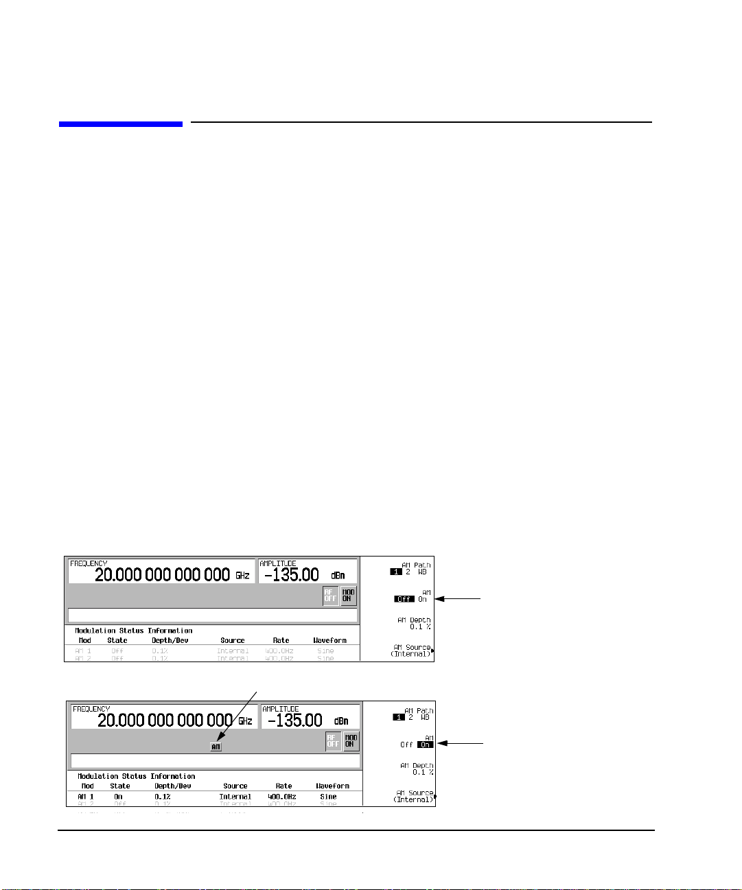
Basic Operation
Modulating a Signal
Modulating a Signal
This section describes how to turn on a modulation format, and how to apply it to the RF output.
Turning On a Modulation Format
A modulation format can be turned on prior to or after setting the signal parameters.
1. Access the first menu within the modulation format.
This menu displays a softkey that associates the format’s name with off and on. For example,
AM Off On
. For some formats, the off/on key may appear in additional menus other than the first one.
2. Press the modulation format off/on key until On highlights.
Figure 2-11 shows the portion of the AM modulation format’s first menu that displays the state of the
modulation format, as well as the active modulation format annunciator.
The modulation format generates, but the carrier signal is not modulated until you apply it to the RF
output (see page 51).
Depending on the modulation format, the signal generator may require a few seconds to build the signal.
Within the digital formats (E8267C PSG with Option 002/602 only), you may see a BaseBand
Reconfiguring status b ar appear on the d isplay. Once the signal is generated, an annunciator showing the
name of the format appears on the display, indicating that the modulation format is active. For digital
formats (E8267C PSG with Option 002/602 only), the I/Q annunciator appears in addition to the name of
the modulation format.
AM >
Figure 2-11 Example of AM Modulation Format Off and On
First AM Menu
Modulation format is off
Active Modulation Format Annunciator
Modulation format is on
50 Chapter 2
Page 61
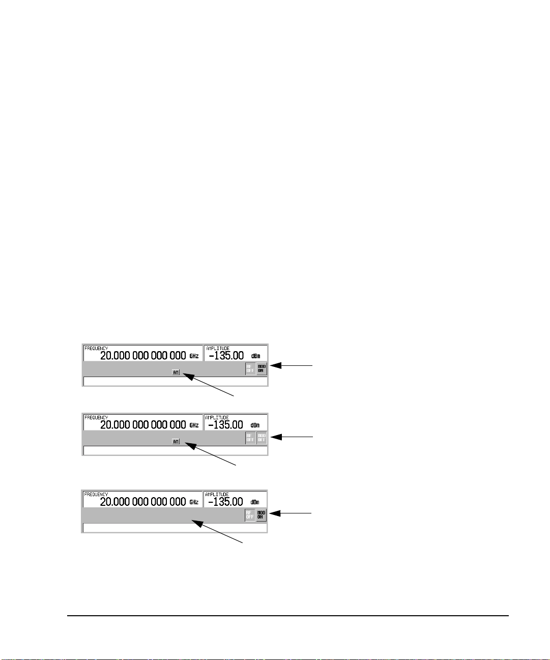
Basic Operation
Modulating a Signal
Applying a Modulation Format to the RF Output
The carrier signal is modulated when the Mod On/Off key is set to On , and an indi vidual modulat ion f ormat is
active.
When the
Mod On/Off key is set to Off, the MOD OFF annunciator appears on the display.When the key is set
to On, the MOD ON annunciator shows in the display, whether or not there is an active modulation format.
The annunciators simply indicate whether the carrier signal will be modulated when a modulation format is
turned on.
To Turn RF Output Modulation On
Press the
Mod On/Off key until the MOD ON annunciator appears in the display.
The carrier signal should be modulated with all active modulation formats. This is the factory default.
To Turn RF Output Modulation Off
Press the
Mod On/Off key until the MOD OFF annunciator appears in the display.
The carrier signal is no longer modulated or capable of being modulated when a modulation format is active.
Figure 2-12 Carrier Signal Modulation Status
Mod Set to On—Carrier is Modulated
AM Modulation Format is Active
Mod Set to Off—Carrier is
not Modulated
AM Modulation Format is Active
Mod Set to On—Carrier is
not Modulated
No Active Modulation Format
Chapter 2 51
Page 62

Basic Operation
Using Data Storage Functions
Using Data Storage Functions
This section explains how to use the two forms of signal generator data storage: the memory catalog and the
instrument state register.
Using the Memory Catalog
The Memory Catalog is the signal generator’s interface for viewing, storing, and saving files; it can be
accessed through the signal generator’s front panel or a remote controller. (For information on performing
these tasks remotely, see the Programming Guide.)
Table 2-1 Memory Catalog File Types and Associated Data
Binary binary data
State instrument state data (controlling instrument operating
parameters, such as frequency, amplitude, and mode)
LIST sweep data from the List Mode Values table including
frequency, amplitude, and dwell time
User Flatness user flatness calibration correction pair data (user-defined
frequency and corresponding amplitude correction values)
FIR Finite Impulse Response (FIR) filter coefficients
ARB Catalog Types (E8267C PSG with Option 002/602 only) user created files -
Waveform Catalog Types: WFM1 (waveform file),
NVARB Catalog Types:
NVWFM (non-volatile, ARB waveform file),
NVMKR (non-volatile, ARB waveform marker file),
Seq (ARB sequence file),
MTONE (ARB multitone file),
DMOD (ARB digital modulation file),
MDMOD (ARB multicarrier digital modulation file)
Modulation Catalog Types (E8267C PSG with Option 002/602 only) associated data for I/Q
and FSK (frequency shift keying) modulation files
Shape burst shape of a pulse
Bit Bit
52 Chapter 2
Page 63

Basic Operation
Using Data Storage Functions
Storing Files to the Memory Catalog
To store a file to the memory catalog, first create a file. For this example, use the default list sweep table.
1. Press
2. Press
Preset.
Sweep/List > Configure List Sweep > More (1 of 2) > Load/Store.
This opens the “Catalog of List Files”.
3. Press
Store to File.
This displays a menu of alphabet ical soft ke ys for naming the file. Store to: is displayed in the active
function area.
4. Enter the file name LIST1 using the al phab et ica l so ft key s and t he nu meric keypad (for the numbers 0 to
9).
5. Press
Enter.
The file should be displayed in the “Catalog of List Files”, showing the file name, file type, file size, and
the date and time the file was modified.
Viewing Stored Files in the Memory Catalog
1. Press
Utility > Memory Catalog > Catalog Type.
All files in the memory catalog are listed in alphabetical order, regardless of which catalog type you
select. File information appears on the display and includes the file name, file type, file size, and the date
and time the file was modified.
2. Press
List.
The “Catalog of List Files” is displayed.
3. Press
Catalog Type > State.
The “Catalog of State Files” is displayed.
4. Press
Catalog Type > All.
The “Catalog of All Files” is displayed. For a complete list of file types, refer to Table 2-1 on page 52.
Chapter 2 53
Page 64

Basic Operation
Using Data Storage Functions
Using the Instrument State Register
The instrument state register is a s ection o f m emory divi ded into 10 sequence s (numbered 0 through 9) each
containing 100 registers (numbered 00 through 99). It is used to store and recall instrument settings. It
provides a quick way to reconfigure the signal generator when switching between different signal
configurations. Once an instrument state has been saved, you can recall the instrument s ettings for that state
with minimum effort.
NOTE List sweep data is not saved within an instrument state. For instructions on saving list sweep
data, see “Storing Files to the Memory Catalog” on page 53.
Saving an Instrument State
1. Preset the signal generator, then enables amplitude modulation (the AM annunciator will turn on):
a. Press
b. Press
c. Press
2. Press
Frequency > 800 > MHz.
Amplitude > 0 > dBm.
AM > AM Off On.
Save > Select Seq.
The sequence number becomes the active function. Th e signal generator displays the last seq uence used.
Using the arrow keys, set the sequence to 1.
3. Press
Select Reg.
The register number in sequence 1 becomes the active function. The signal generator displays either the
last register used accompanied by the text: (in use), or (if no registers are in use) register 00
accompanied by the text: (availabl e). Use the arrow keys to select register 01.
4. Press
Save Seq[1] Reg[01].
This saves this instrument state in sequence 1, register 01 of the instrument state register.
5. Press
Add Comment to Seq[1] Reg[01].
This enables you to add a descriptive comment to sequence 1 register 01.
6. Using the alphanumeric softkeys or the knob, enter a comment and press
7. Press
Edit Comment In Seq[1] Reg[01].
Enter.
If you wish, you can now change the descriptive comment for sequence 1 register 01.
After making changes to an instrument state, you can save it back to a specific register by highlighting that
register and pressing
Re-SAVE Seq[n] Reg[nn].
54 Chapter 2
Page 65

Basic Operation
Using Data Storage Functions
Recalling an Instrument State
Using this procedure, you will learn how to recall instrument settings saved to an instrument state register.
1. Press
2. Press the
3. Press
Preset.
Recall hardkey.
Notice that the
RECALL Reg.
Select Seq softkey shows sequence 1. (This is the last sequence that you used.)
The register to be recalled in sequence 1 becomes the active function. Press the up arrow key once to
select register 1 . Your stored instrument state settings should have been recalled.
Deleting Registers and Sequences
These procedures describe how to delete registers and sequences saved to an instrument state register.
Deleting a Specific Register w ithin a Sequenc e
1. Press
2. Press the
3. Press
4. Press
5. Press
Preset.
Recall or Save hardkey.
Notice that the
Select Seq and enter the sequence number containing the register you want to delete.
Select Reg and enter the register number you want to delete.
Notice that the
Delete Seq[n] Re g [n n].
Select Seq softkey shows the last sequence that you used.
Delete Seq[n] Reg[nn] should be loaded with the sequence and register you want to delete.
This deletes the chosen register.
Chapter 2 55
Page 66

Basic Operation
Using Data Storage Functions
Deleting All Registers within a Sequence
1. Press
2. Press the
3. Press
4. Press
Preset.
Recall or Save hardkey.
Notice that the
Select Seq and enter the sequence number containing the registers you want to delete.
Delete all Regs in Seq[n].
Select Seq softkey shows the last sequence that you used.
This deletes all registers in the selected sequence.
Deleting All Sequences
CAUTION Be sure you want to delete the contents of all registers and all sequences in the instrument
state register.
1. Press
2. Press the
3. Press
Preset.
Recall or Save hardkey.
Notice that the
Delete All Sequences.
Select Seq softkey shows the last sequence that you used.
This deletes all of the sequences saved in the instrument state register.
56 Chapter 2
Page 67

Basic Operation
Enabling Options
Enabling Options
Y o u can retrofit your signal generator after purchase to add new capabilities. Some new optional features are
implemented in hardware that you must install. Some options are implemented in software, but requ ir e the
presence of optional hardware in the instrument. This example shows you how to enable software options.
Enabling a Software Option
A license key (provided on the license key certificate) is required to enable each software option.
1. Access the Software Options menu:
Utility > Instrument Adjustments > Instrument Options > Software Options.
The following is an example of the signal generator display, which lists any enabled software options,
and any software options that can be enabled:
2. Verify that the host ID shown on the display matches the host ID on the license key certificate. The host
ID is a unique number for every instrument. If the host ID on the license key certificate does not match
your instrument, the license key cannot enable the software option.
3. Verify that any required hardware is installed. Because some software options are linked to specific
hardware options, before the software option can be enabled, the appropriate hardware option must be
installed. For example, Option 420 (radar simulation modulation format ) requires that Option 002/602
(internal baseband generator) be installed. If the software option that you intend to install is listed in a
grey font, the required hardware may not be installed (look for an X in the “Selected” column of the
appropriate hardware option in the Hardware Options menu).
Chapter 2 57
Page 68

Basic Operation
Enabling Options
4. Enable the software option:
a. Highlight the desired option.
b. Press
Modify License Key, and enter the 12-character license key (from the license key certificate).
c. Verify that you want to reconfigure the signal generator with the new option:
Proceed With Reconfiguration > Confirm Change
The instrument enables the option and reboots.
58 Chapter 2
Page 69

3 Optimizing Performance
In the following sections, this chapter describes proced ures that improve th e performance of the Agilent PSG
signal generator.
• Selecting ALC Bandwidth (below)
• “Using External Leveling” on page 60
• “Creating and Applying User Flatness Correction” on page 64
• “Adjusting Reference Oscillator Bandwidth (Option UNR)” on page 76
Selecting ALC Bandwidth
For internal leveling, the signal generator uses automatic leveling control (ALC) circuitry prior to the RF
output. ALC bandwidth has five selections: automatic, 100 Hz, 1 kHz, 10 kHz, and 100 kHz. In automatic
mode (the preset selection), the signal generator automatically adjusts the ALC bandwidth among three of
the four possible settings, depending on the active functions (see Figure 3-1).
Figure 3-1 Decision Tree for Automatic ALC Bandwidth Selection
RF OUTPUT
< 2 MHz
Yes
No
ALC BW
100 Hz
AM OFF
PULSE OFF
Yes
ALC BW
1 kHz
No
AM OFF
PULSE ON
Yes
ALC BW
10 kHz
No No
AM ON
PULSE ON
Yes Yes
ALC BW
100 kHz
To Select an ALC Bandwidth
Press Amplitude > ALC BW > 100 Hz, 1 kHz, 10 kHz, or 100 kHz.
This overrides the automatic ALC bandwidth selection with your specific selection.
AM ON
PULSE OFF
59
Page 70
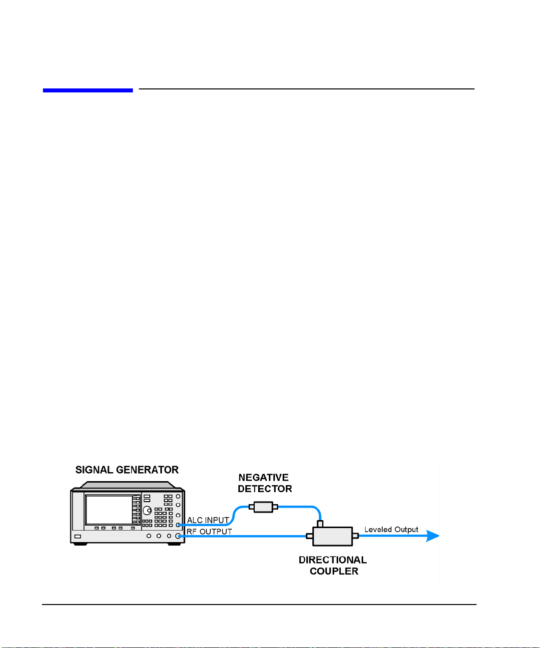
Optimizing Performance
Using External Leveling
Using External Leveling
The PSG signal generator can be externally leveled by connecting an external sensor at the point where
leveled RF output power is desired. This sensor detects changes in RF output power and returns a
compensating voltage to the signal generator’s ALC input. The ALC circuitry raises or lowers (levels) the
RF output power based on the voltage received from the external sensor, ensuring constant power at the
point of detection.
There are two types of external leveling available on the PSG. You can use external leveling with a detector
and coupler/power splitter setup, or a millimeter-wave source module.
To Level with Detectors and Couplers/Splitters
Figure 3-2 illustrates a typical external leveling setup. The power level feedback to the ALC circuitry is
taken from the external negative detector, rather than the internal signal generator detector. This feedback
voltage controls the ALC system, leveling the RF output po wer at the point of detection.
To use detectors and couplers/splitters for external leveling at an RF output frequency of
10 GHz and an amplitude of 0 dBm, follow the instructions in this section.
Required Equi pment
• Agilent 8474E negative detector
• Agilent 87301D directional coupler
• cables and adapters, as required
Connect the Equipment
Set up the equipment as shown in Figur e 3-2.
Figure 3-2 External Detector Leveling with a Directional Coupler
60 Chapter 3
Page 71

Configure the Signal Generator
Optimizing Performance
Using External Leveling
1. Press
2. Press
3. Press
4. Press
5. Press
Preset.
Frequency > 10 > GHz.
Amplitude > 0 > dBm.
RF On/Off.
Leveling Mode > Ext Detector.
This deactivates the internal ALC detector and switches the ALC input path to the front panel ALC
INPUT connector. The EXT indicator is activated in the AMPLITUDE area of the display.
NOTE For signal generators with Option 1E1, notice that the ATTN HOLD (attenuator hold)
annunciator is displayed. During external leveling, the signal generator automatically
uncouples the attenuator from the ALC system for all external leveling points. W hi le in this
mode, the RF output amplitude adjustment is limited to −20 to +25 dBm, the adjustment
range of the ALC circuitry. For more information, see “External Le veling with Option 1E1
Signal Generators” on page 63.
6. Observe the coupling factor printed on the directional coupler at the detector port. Typically , this value is
−10 to −20 dB.
Enter the positive dB value of this coupling factor into the signal generator.
7. Press
More (1 of 2) > Ext Detector Coupling Factor > 16 (or t he positive representation of the va l ue listed at
the detector port of the directional coupler) >
dB.
Leveled output power is now available at the output of the directional coupler.
NOTE While operating in external leveling mode, the signal generator’s displayed RF output
amplitude is affected by the coupling factor value, resulting in a calculated approximation of
the actual RF output amplitude. To determine the actual RF output amplitude at the point of
detection, measure the voltage at the external detector output and refer to Figure 3-3 or
measure the power directly with a power meter.
Chapter 3 61
Page 72

Optimizing Performance
Using External Leveling
Determinin g the Leveled Output Pow er
Figure 3-3 shows the input power versus output voltage characteristics for typical Agilent Technologies
diode detectors. Using this chart, you can determine the leveled power at the diode detector input by
measuring the external detector output voltage. You must then add the coupling factor to determine the
leveled output power. The range of power adjustment is approximately -20 to +25 dBm.
Figure 3-3 Typical Diode Detector Response at 25° C
62 Chapter 3
Page 73

Optimizing Performance
Using External Leveling
External Leveling with Option 1E1 Signal Generators
Signal generators with Option 1E1 contain a step attenuator prior to the RF output connector. During
external leveling, the signal generator automatically holds the present attenuator setting (to avoid power
transients that may occur during attenuator switching) as the RF amplitude is changed. A balance must be
maintained between the amount of attenuation and the optimum ALC level to achieve the required RF
output amplitude. For optimum accuracy and minimum noise, the ALC level should be greater than −10
dBm.
For example, leveling the CW output of a 30 dB gain amplifier to a level of −10 dBm requires the output of
the signal generator to be approximately −40 dBm when leveled. This is beyond the amplitude limits of the
ALC modulator alone, r e su lting i n an unl ev el ed R F ou tp ut. Inserting 45 dB of attenuation res ult s in an A LC
level of +5 dBm, well within the range of the ALC modulator.
NOTE In the example above, 55 dB is the preferred attenuation choice, resulting in an ALC level
of +15 dBm. This provides adequate dynami c range for AM or other funct ions that vary the
RF output amplitude.
To achieve the optimum ALC level at the signal generator RF output of −40 dBm for an unmodulated
carrier, follow these steps:
1. Press
2. Press Set ALC Level > 5 > dBm.
This sets the attenuator to 45 dB and the ALC level to +5 dBm, resulting in an RF output amplitu de of -4 0
dBm, as shown in the AMPLITUDE area of the display.
To obtain flatness-corrected power, refer to “Creating and Applying User Flatness Correction” on page 64.
Amplitude > Set Atten > 45 > dB.
To Level with a mm-Wave Source Module
Millimeter-wave source module leveling is similar to external detector leveling. The power level feedback
signal to the ALC circuitry is taken from the millimeter-wave source module, rather than the internal sig nal
generator detector. This feedback signal levels the RF output power at the mm-wave source module output
through the signal generator’s rear panel SOURCE MODULE interface connector.
For instructions and setups, see “Extending the Frequency Range with a mm-Wave Source Module” on
page 47.
Chapter 3 63
Page 74

Optimizing Performance
Creating and Applying User Flatness Correct ion
Creating and Applying User Flatness Correction
User flatness correction allows the digital adjustment of RF output amplitu de for up to 1601 frequency
points in any frequency or sweep mode. Using an Agilent E4416A/17A or E4418B/19B power meter
(controlled by the signal generator through GPIB) to calibrate the measurement system, a table of power
level corrections is created for frequencies where power level variations or losses occur. These frequencies
may be defined in sequential linear steps or arbitrarily spaced.
To allow different correction arrays for different test setups or different frequency ranges, you may save
individual user flatness correction tables to the signal generator ’s memory catalog and recall them on
demand.
Use the steps in the next sections to create and apply user flatness correction to the signal generator’s RF
output.
Afterward, use the steps in “Recalling and Applying a User Flatness Correction Array” on page 68 to recall
a user flatness file from the memory catalog and apply it to the signal generator’s RF output.
Creating a User Flatness Correction Array
In this example, you create a user flatness correction array. The flatness correction array contains ten
frequency correction pairs (amplitude correction values for specified frequencies), from 1 to 10 GHz in
1 GHz intervals.
An Agilent E4416A/17A/18B/19B power meter (controlled by the signal generator via GPIB) and E4413A
power sensor are used to measure the RF output amplitude at the specified correction frequencies and
transfer the results to the signal generator. The signal generator reads the power level data from the power
meter, calculates the correction values, and stores the correction pairs in the user flatness correction array.
If you do not have the required Agilent power meter , or if your power meter does not have a GPIB interface,
you can enter correction values manually.
Required Equi pment
• Agilent E4416A/17A/18B/19B power meter
• Agilent E4413A E Series CW power sensor
• GPIB interface cable
• adapters and cables, as required
NOTE If the setup has an external leveling configuration, the equipment setup in Figure 3-4
assumes that the steps necessary to correctly level the RF output have been followed. If yo u
have questions about external leveling, refer to “Using External Leveling” on page 60.
64 Chapter 3
Page 75

Optimizing Performance
Creating and Applying User Flatness Correction
Configure the Power Meter
1. Select SCPI as the remote language for the power meter.
2. Zero and calibrate the power sensor to the power meter.
3. Enter the appropriate power sensor calibration factors into the power meter as appropriate.
4. Enable the power meter’s cal factor array.
NOTE For operating information on a particular power meter/sensor, refer to its operating guide.
Connect the Equipment
Connect the equipment as shown in Figure 3-4.
NOTE During the process of creating the user flatness correction array, the power meter is slaved
to the signa l generator via GPIB. No other controllers are allowed on the GPI B in ter f ace.
Figure 3-4 User Flatness Correction Equipment Setup
Chapter 3 65
Page 76

Optimizing Performance
Creating and Applying User Flatness Correct ion
Configure the Signal Generator
1. Press
Preset.
2. Configure the signal generator to interface with the power meter.
a. Press
b. Press
c. For E4417A and E4419B models, press
d. Press
Amplitude > More (1 of 2) > User Flatness > More (1 of 2) > Power Meter > E4416A, E4417A, E4418B,
or
E4419B.
Meter Address > enter the power meter’s GPIB address > Enter.
Meter Channel A B to select the power meter’s active channel.
Meter Timeout to adjust the length of time before the instrument generates a timeout error if
unsuccessfully attempting to communicate with the power meter.
3. Press
More (2 of 2) > Configure Cal Array > More (1 of 2) > Preset List > Confirm Pr es et.
This opens the User Flatness table editor and presets the cal array frequency/correction list.
4. Press
Configure Step Array.
This opens a menu for entering the user flatness step array data.
5. Press
6. Press
7. Press
Freq Start > 1 > GHz.
Freq Stop > 10 > GHz.
# of Points > 10 > Enter.
Steps 4, 5, and 6 enter the desired flatness-corrected frequencies into the step array.
8. Press
Return > Load Cal Array From Step Array > Confirm Load From Step Data .
This populates the user flatness correction array with the frequency settings defined in the step array.
9. Press
10. Press
Amplitude > 0 > dBm.
RF On/Off.
This activates the RF output and the RF ON annunciator is displayed on the signal generator.
66 Chapter 3
Page 77

Optimizing Performance
Creating and Applying User Flatness Correction
Perform the User Flatness Correction
NOTE If you are not us ing an A gil ent E 4416A/17A/18B/19B power meter , o r i f y our pow er met er
does not have a GPIB interface, you can perform the user flatness correction manually. For
instructions, see “Performing the User Flatness Correction Manually” on page 67.
1. Press
More (1 of 2) > User Flatness > Do Cal.
This creates the user flatness amplitude correction value table entries. The signal generator enters the
user flatness correction routine and a progress bar is shown on the display.
2. Press
Done.
This loads the amplitude correction values into the user flatness correction array.
If desired, press
Configure Cal Array.
This opens the user flatness correction array , where you can view the stored amplitude correction v alues.
The user flatness correction array title displays User Flatness: (UNSTORE D) indicating that the
current user flatness correction array data has not been saved to the memory catalog.
Performing the User Flatness Correction Manually
If you are not using an Agilent E4416A/17A/18B/19B power meter, or if your power meter does not have a
GPIB interface, complete the steps in this section and then continue with the user flatne ss correction tutorial.
1. Press
More (1 of 2) > User Flatness > Configu re C a l Array.
This opens the User Flatness table editor and places the cursor over the frequency value
(1 GHz) for row 1. The RF output changes to the frequency value of the table row containing the cursor
and 1.000 000 000 00 is displayed in the AMPLIT UDE area of the display.
2. Observe and record the measured value from the power meter.
3. Subtract the measured value from 0 dBm.
4. Move the table cursor over the correction value in row 1.
5. Press
Edit Item > enter the difference value from step 3 > dB.
The signal generator adjusts the RF output amplitude based on the correction value entered.
6. Repeat steps 2 through 5 until the power meter reads 0 dBm.
7. Use the down arrow key to place the cursor over the frequency value
for the next row . Th e RF output changes to the freq uency value of the table row containing the curs or, as
shown in the AMPLITUDE area of the display.
8. Repeat steps 2 through 7 for every entry in the User Flatness table.
Chapter 3 67
Page 78

Optimizing Performance
Creating and Applying User Flatness Correct ion
Save the User Flatness Correction Data to the Me mory Catalog
This process allows you to save the user flatness correction data as in the signal generator’ s memory catalog.
With several user flatness correction files saved to the memory catalog, any file can be recalled, loaded into
the correction array, and applied to the RF output to satisfy specific RF output flatness requirements.
1. Press
2. Press
Load/Store.
Store to File.
3. Enter the file name FLATCAL1 using the alphanumeric softkeys, numeric keypad, or the knob.
4. Press
Enter.
The user flatness correction array file FLATCAL1 is now stored in the memory catalog as a UFLT file.
Applying a User Flatness Correction Array
Press
Return > Return > Flatness Off On.
This applies the user flatness correction array to the RF output. The UF indicator is activated in the
AMPLITUDE section of the signal generator’s display and the frequency correction data contained in the
correction array is applied to the RF output amplitude.
Recalling and Applying a User Flatness Correction Array
Before performing the steps in this section, complete “Creating a User Flatness Correction Array” on
page 64.
1. Press
2. Press
3. Press
Preset.
Amplitude > More (1 of 2) > User Flatness > Configure Cal Array > More (1 of 2) >
Preset List > Confirm Preset.
More (2 of 2) > Load/Store.
4. Ensure that the file FLATCAL1 is highlighted.
5. Press
Load From Selected File > Confirm Load From File.
This populates the user flatness correction array with the data contained in the file FLATCAL1. The user
flatness correction array title displays User Flatness: FLATCA L1.
6. Press
Return > Flatness Off On.
This applies the user flatness correction data contained in FLATCAL1.
68 Chapter 3
Page 79

Optimizing Performance
Creating and Applying User Flatness Correction
Returning the Signal Generator to GPIB Listener Mode
During the user flatness correction process, the power meter is slaved to the signal generator via GPIB, and
no other controllers are allowed on the GPIB interface. The signal generator operates in GPIB talker mode,
as a device controller for the power meter. In this operating mode, it cannot receive SCPI commands via
GPIB.
If the signal generator is to be interfaced to a remote controlle r after performing the user flatness correction,
its GPIB controller mode must be changed from GPIB talker to GPIB listener.
If an RF carrier has been previously conf igured , yo u mus t sav e the pr esent instru ment s tate befor e return ing
the signal generator to GPIB listener mode.
1. Save your instrument state to the instrument state register.
For instruc tions, see “Saving an Instrument State” on page 54.
2. Press
3. Recall your instrument state from the instrument state register.
GPIB Listener Mode.
This presets the signal generator and returns it to GPIB listener mode. The signal generator can now
receive remote commands executed by a remote controller connected to the GPIB interface.
For instruc tions, see “Saving an Instrument State” on page 54.
Creating a User Flatness Correction Array with a mm-Wave Source Module
In this example, a user flatness correction array is created to provide flatness-corrected power at the output
of an Agilent 83554A millimeter-wave source module dri ven by an E8247C signal generator.
The flatness correction array contains 28 frequency correction pairs (amplitude correction values for
specified frequencies), from 26.5 to 40 GHz in 500 MHz intervals. This will result in 28 evenly spaced
flatness corrected frequencies between 26.5 GHz and 40 GHz at the output of the 83554A millimeter-wave
source module.
An Agilent E4416A/17A/18B/19B power meter (controlled by the signal generator via GPIB) and R8486A
power sensor are used to measure the RF output amplitude of the millimeter-wave source module at the
specified correction frequencies and transfer the results to the signal generator. The signal generator reads
the power level data from the power meter, calculates the correction values, and stores the correction pairs in
the user flatness correction array.
If you do not have the required Agilent power meter , or if your power meter does not have a GPIB interface,
you can enter correction values manually.
Chapter 3 69
Page 80

Optimizing Performance
Creating and Applying User Flatness Correct ion
Required Equi pment
• Agilent 83554A millimeter-wave source module
• Agilent E4416A/17A/18B/19B power meter
• Agilent R8486A power sensor
• Agilent 8349B microwave amplifi er (requ i red for si gn al gener at ors wit hou t Opti on 1EA)
• GPIB interface cable
• adapters and cables as required
NOTE The equipment setups in Figure 3-5 and Figure 3-6 assume that the steps necessary to
correctly level the RF output have been foll owed. If you have questi ons abou t levelin g with
a millimeter-wave source module, refer to “To Level with a mm-Wave Source Module” on
page 63.
Configure the Power Meter
1. Select SCPI as the remote language for the power meter.
2. Zero and calibrate the power sensor to the power meter.
3. Enter the appropriate power sensor calibration factors into the power meter as appropriate.
4. Enable the power meter’s cal factor array.
NOTE For operating informatio n on your parti cular pow er mete r/sen so r, refer to their operating
guides.
70 Chapter 3
Page 81

Optimizing Performance
Creating and Applying User Flatness Correction
Connect the Equipment
CAUTION To prevent damage to the signal generator, turn off the line power to the signal generator
before connecting the source module interface cable to the rear panel SOURCE MODULE
interface connector.
1. Turn off the line power to the signal generator.
2. Connect the equipment. For standard signal generators, use the setup in Figure 3-5. For Option 1EA
signal generators, use the setup in Figure 3-6.
NOTE During the process of creating the user flatness correction array, the power meter is slaved to
the signal generator via GPIB. No other controllers are allowed on the GPIB interface.
Figure 3-5 User Flatness with mm-Wave Source Module for a Signal Generator without Option 1EA
Chapter 3 71
Page 82

Optimizing Performance
Creating and Applying User Flatness Correct ion
Figure 3-6 User Flatness with mm-Wave Source Module and Option 1EA Signal Generator
NOTE To ensure adequate RF amplitude at the mm-wave source module RF input when using
Option 1EA signal generators, maximum amplitude loss through the adapters and cables
connected between the signal generator’s RF output and the mm-wave source module’s RF
input should be less than 1.5 dB.
Configure the Signal Generator
1. Turn on the signal generator’s line power. At power-up, the signal generator automatically does the
following:
• senses the mm-wave source module
• switches the signal generator’s leveling mode to external/source module
• sets the mm-wave source module frequency and amplitude to the source module’s preset values
• displays the RF output frequency and amplitude available at the mm-wave source module output
The MMMOD indicator in the FREQUENCY area and the MM indicator in the AMPLITUDE area of the signal
generator’s display indicate that the mm-wave source module is active
NOTE For specific frequency/amplitude ranges, see the mm-wave source module specifications.
72 Chapter 3
Page 83

Creating and Applying User Flatness Correction
2. Configure the signal generator to interface with the power meter.
Optimizing Performance
a. Press
b. Press
c. For E4417A and E4419B models, press
d. Press
Amplitude > More (1 of 2) > User Flatness > More (1 of 2) > Power Meter > E4416A, E4417A, E4418B,
or
E4419B.
Meter Address > enter the power meter’s GPIB address > Enter.
Meter Channel A B to select the power meter’s active channel.
Meter Timeout to adjust the length of time before the instrument generates a timeout error if
unsuccessfully attempting to communicate with the power meter.
3. Press
More (2 of 2) > Configure Cal Array > More (1 of 2) > Preset List > Confirm Pr es et.
This opens the User Flatness table editor and resets the cal array frequency/correction list.
4. Press
Configure Step Array.
This opens a menu for entering the user flatness step array data.
5. Press
6. Press
7. Press
Freq Start > 26.5 > GHz.
Freq Stop > 40 > GHz.
# of Points > 28 > Enter.
This enters the desired flatness-corrected frequencies (26.5 GHz to 40 GHz in 500 MHz intervals) into
the step array .
8. Press
Return > Load Cal Array From Step Array > Confirm Load From Step Data.
This populates the user flatness correction array with the frequency settings defined in the step array.
9. Press
Amplitude > 0 > dBm.
10. Press
RF On/Off.
This activates the RF output and the RF ON annunciator is displayed on the signal generator.
Perform the User Flatness Correction
NOTE If you are not us ing an A gil ent E 4416A/17A/18B/19B power meter , o r i f y our pow er met er
does not have a GPIB interface, you can perform the user flatness correction manually. For
instructions, see Performing the User Flatness Correction Manually below.
1. Press
More (1 of 2) > User Flatness > Do Cal.
This creates the user flatness amplitude correction value table entries. The signal generator begins the
user flatness correction routine and a progress bar is shown on the display.
Chapter 3 73
Page 84

Optimizing Performance
Creating and Applying User Flatness Correct ion
2. When prompted, press Done.
This loads the amplitude correction values into the user flatness correction array.
If desired, press
Configure Cal Array.
This opens the user flatness correction array , wher e you can view the list of defined frequencies and their
calculated amplitude correction values. The user flatness correction array title displays User
Flatness: (UNSTORE D) indicating that the current user flatness correction array data has not been
saved to the memory catalog.
Performing the User Flatness Correction Manually
If you are not using an Agilent E4416A/17A/18B/19B power meter, or if your power meter does not have a
GPIB interface, complete the steps in this section and then continue with the user flatne ss correction tutorial.
1. Press
More (1 of 2) > User Flatness > Configu re C a l A r r ay.
This opens the User Flatness table editor and places the cursor over the frequency value (26.5 GHz) for
row 1. The RF output changes to the frequency value of the tab le row containing the cursor and 26.500
000 000 00 is displayed in the AMPLITUDE area of the display.
2. Observe and record the measured value from the power meter.
3. Subtract the measured value from 0 dBm.
4. Move the table cursor over the correction value in row 1.
5. Press
Edit Item > enter the difference value from step 3 > dB.
The signal generator adjusts the RF output amplitude based on the correction value entered.
6. Repeat steps 2 through 5 until the power meter reads 0 dBm.
7. Use the down arrow key to place the cursor over the frequency value for the next row. The RF output
changes to the frequency value highlighted by the cursor, as shown in the AMPLITUDE area of the
display.
8. Repeat steps 2 through 7 for each entry in the User Flatness table.
74 Chapter 3
Page 85

Optimizing Performance
Creating and Applying User Flatness Correction
Save the User Flatness Correction Data to the Me mory Catalog
This process allows you to save the user flatness correction data as a file in the signal generator’s memory
catalog. With several user flatness correction files saved to the memory catalog, specific files can be
recalled, loaded into the correction array, and applied to the RF output to satisfy various RF output flatness
requirements.
1. Press
2. Press
Load/Store.
Store to File.
3. Enter the file name FLATCAL2 using the alphanumeric softkeys and the numeric keypad.
4. Press
Enter.
The user flatness correction array file FLATCAL2 is now stored in the memory catalog as a UFLT file.
Applying the User Flatness Correction Array
1. Press
Return > Return > Flatness Off On.
This applies the user flatness correction array to the RF output. The UF indicator is activated in the
AMPLITUDE section of the signal generator’s display and the frequency correction data contained in the
correction array is applied to the RF output amplitude of the mm-wave source module.
Recalling and Applying a User Flatness Correction Array
Before performing the steps in this section, complete the section “Creating a User Flatness Correction Array
with a mm-Wave Source Module” on page 69.
1. Press
2. Press
3. Press
Preset.
Amplitude > More (1 of 2) > User Flatness > Configure Cal Array > More (1 of 2) >
Preset List > Confirm Preset.
More (2 of 2) > Load/Store.
4. Ensure that the file FLATCAL2 is highlighted.
5. Press
Load From Selected File > Confirm Load From File.
This populates the user flatness correction array with the data contained in the file FLATCAL2. The user
flatness correction array title displays User Flatness: FLATCA L2.
6. Press
Return > Flatness Off On.
This activates flatness correction using the data contained in the file FLATCAL2.
Chapter 3 75
Page 86

Optimizing Performance
Adjusting Reference Oscillator Bandwidth (Option UNR)
Adjusting Reference Oscillator Bandwidth (Option UNR)
The reference oscillator bandwidth (sometimes referred to as loop bandwidth) in signal generators with
Option UNR (improved close-in phase noise) is adjustable in fixed steps for either an internal or external
10 MHz frequency reference. The reference bandwidth can be set to 25, 55, 125, 300, or 650 Hz; models
without option UNR have a fixed reference oscillator bandwidth of about 15 Hz.
The reference oscillator bandwidth is the frequency below which the PSG derives its reference directly from
the internal or external frequency reference. Above this frequency, stability and phase noise are governed by
the synthesizer hardware within the PSG.
To optimize the overall phase noise performance of the signal generator for your particular application,
make this adjustment depending on your confidence in the stability and phase noise of the external or
internal reference versus the synthesizer hardware for various frequency offsets from the carrier.
To Select the Reference Oscillator Bandwidth
When using the internal timebase reference:
1. Press
2. Select the desired bandwidth.
When using an external t imebase reference:
1. Press
2. Select the desired bandwidth.
Utility > Instrument Adjustments > Reference Oscillator Adjustment > Internal Ref Bandwidth.
Utility > Instrument Adjustments > Reference Oscillator Adjustment > External Ref Bandwidth.
To Restore Factory Default Settings:
Internal Timebase: 125 Hz
External Timebase: 25 Hz
Press
Utility > Instrument Adjustments > Reference Oscillator Adjustment > Restore Factory Defaults.
76 Chapter 3
Page 87

4 Analog Modulation
In the following sections, this chapter describes the analog modulation capability in Agilent E8257C P SG
Analog and E8267C PSG Vector Signal Generators.
• “Analog Modulation Waveforms” on page 78
• “Configuring AM” on page 79
• “Configuring FM” on page 80
• “Configuring ΦM” on page 81
• “Configuring Pulse Modulation” on page 82
• “Configuring the LF Output” on page 83
77
Page 88

Analog Modulation
Analog Modulation Waveforms
Analog Modulation Waveforms
The signal generator can modulate the RF carrier with four types of analog modulation:
• amplitude,
• frequency,
•phase, and
•pulse.
Available internal waveforms include:
Sine sine wave with adjustable amplitude and frequency
Dual-Sine dual-sine waves with individually adjustable frequencies and a percent-of-
peak-amplitude setting for the second tone (available from function generator only)
Swept-Sine swept-sine wave with adjustable start and stop frequencies, sweep rate, and sweep
trigger settings (available from function gen e rator only)
Triangle triangle wave with adjustable amplitude and frequency
Ramp ramp with adjustable amplitude and frequency
Square square wave with adjustable amplitude and frequency
Noise noise with adjustable amplitude generated as a peak-to-peak value (RMS value is
approximately 80% of the displayed value)
78 Chapter 4
Page 89

Configuring AM
In this example, you will learn how to generate an amplitude-modulated RF carrier.
To Set the Carrier Frequency
1. Press Preset.
Analog Modulation
Configuring AM
2. Press
Frequency > 1340 > kHz.
To Set the RF Output Amplitude
Press Amplitude > 0 > dBm.
To Set the AM Depth and Rate
1. Press the AM hardkey.
2. Press
3. Press
The signal generator is now configured to output a 0 dBm, amplitude-modulated carrier at 1340 kHz with
the AM depth set to 90% and the AM rate set to 10 kHz. The shape of the waveform is a sine wave. Notice
that sine is the default selection for the
AM Depth > 90 > %.
AM Rate > 10 > kHz.
AM Waveform softkey, which can be viewed by pressing (More 1 of 2).
To Turn on Amplitude Modulation
Follow these remaining steps to output the amplitude-modulated signal.
1. Press the
2. Press the front panel
The AM and RF ON annunciators are now displayed. This indicates that you have enabled amplitude
modulation and the signal is now being transmitted from the RF OUTPUT connecto r.
AM Off On softkey to On.
RF On Off key.
Chapter 4 79
Page 90

Analog Modulation
Configuring FM
Configuring FM
In this example, you will learn how to create a frequency-modulated RF carrier.
To Set the RF Output Frequency
1. Press Preset.
2. Press
Frequency > 1 > GHz.
To Set the RF Output Amplitude
Press Amplitude > 0 > dBm.
To Set the FM Deviation and Rate
1. Press the FM/ΦM hardkey.
2. Press
3. Press
The signal generator is now configured to output a 0 dBm, frequency-modulated carrier at 1 GHz with a
75 kHz deviation and a 10 kHz rate. The shape of the waveform is a sine wave. (Notice that sine is the
default for the
FM Dev > 75 > kHz.
FM Rate > 10 > kHz.
FM Waveform softkey. Press More (1 of 2) to see the softkey.)
To Activate FM
1. Press FM Off On to On.
2. Press
The FM and RF ON annunciators are now displayed. This indicates that you have enabled frequency
modulation and the signal is now being transmitted from the RF OUTPUT connecto r.
RF On/Off.
80 Chapter 4
Page 91

Configuring ΦM
In this example, you will learn how to create a phase-modulated RF carrier.
To Set the RF Output Frequency
1. Press Preset.
Analog Modulation
Configuring ΦM
2. Press
Frequency > 3 > GHz.
To Set the RF Output Amplitude
Press Amplitude > 0 > dBm.
To Set the FM Deviation and Rate
1. Press the FM/ΦM hardkey.
2. Press the
3. Press
4. Press
The signal generator is now confi gured to output a 0 dBm, phase-modulated carrier at 3 GHz with a 0.25 p
radian deviation and 10 kHz rate. The shape of the waveform is a sine wave. (Notice that sine is the default
for the
FM ΦM softkey.
FM Dev > .25 > pi rad.
FM Rate > 10 > kHz.
FM Waveform soft key. Press More (1 of 2) to see the softkey.)
To Activate FM
1. Press FM Off On.
2. Press
The FM and RF ON annunciators are now displayed. This indicates that you have enabled phase modulation
and the signal is now being transmitted from the RF OUTPUT connector.
RF On/Off.
Chapter 4 81
Page 92

Analog Modulation
Configuring Pulse Modulation
Configuring Pulse Modulation
In this example, you will learn how to create a pulse-modulated RF carrier.
To Set the RF Output Frequency
1. Press Preset.
2. Press
Frequency > 2 > GHz.
To Set the RF Output Amplitude
Press Amplitude > 0 > dBm.
To Set the Pulse Period and Width
1. Press Pulse > Pulse Period > 100 > usec.
2. Press
The signal generator is now confi gured to output a 0 dBm, pulse-modulated carrier at 2 GHz with a
100-microsecond pulse p eriod and 24-mi crosecond pulse widt h. The pulse s ource is set to Internal Fr ee Run.
(Notice that Internal Free Run is the default for the
Pulse > Pulse Width > 24 > usec.
Pulse Source softkey.)
To Activate Pulse Modulation
Follow these remaining steps to output the pulse-modulated sig nal .
1. Press
2. Press
The Pulse and RF ON annunciators are now displayed. This indicates that you have enabled pulse
modulation and the signal is now being transmitted from the RF OUTPUT connecto r.
Pulse Off On to On.
RF On/Off.
82 Chapter 4
Page 93

Analog Modulation
Configuring the LF Output
Configuring the LF Output
The signal generator has a low frequency (LF) output (described on page 9). The LF output’s source can be
switched between
Using
Internal 1 Monitor or Internal 2 Monitor as the LF output source, the LF output provides a replica of the
signal from the internal source that is being used to modulate the RF output. The specific modulation
parameters for this signal are configured through the AM, FM, or FM menus.
Using
Function Generator 1 or Function Generato r 2 as the LF output source, the function generator section of
the internal modulation source drives the LF output directly. Frequency and waveform are configured from
the LF output menu, not through the AM, FM, or FM menus. You can select the waveform shape from the
following choices:
Sine sine wave with adjustable amplitude and frequency
Dual-Sine dual-sine waves with individually adjustable frequencies and a percent-of-
Swept-Sine a swept-sine wave with adjustable start and stop frequencies, sweep rate, and sweep
Internal 1 Monitor, Internal 2 Monitor, Function Generator 1, or Function Generator 2.
peak-amplitude setting for the second tone (available from function generator 1 only)
trigger settings (available from function generator 1 only)
Triangle triangle wave with adjustable amplitude and frequency
Ramp ramp with adjustable amplitude and frequency
Square square wave with adjustable amplitude and frequency
Noise noise with adjustable amplitude generated as a peak-to-peak value (RMS value is
approximately 80% of the displayed value)
DC direct current with adjustable amplitude
NOTE The LF Out Off On softkey controls the operating state of the LF output. However when the
LF output source selection i s
Internal Monitor, you have three ways of controlling the output.
You can use the modulation source (AM, FM, or FM) on/off key, the LF output on/off key,
or the
Mod On/Off softkey.
The RF On/Off hardkey does not apply to the LF OUTPUT connector.
Chapter 4 83
Page 94

Analog Modulation
Configuring the LF Output
To Configure the LF Output with an Internal Modulation Source
In this example, the internal FM modulation is the LF output source.
NOTE Internal modulation (Internal Monitor) is the default LF output source.
Configuring the Internal Modulation as the LF Output Source
1. Press
2. Press the
3. Press
4. Press
5. Press
Preset.
FM/ΦM hardkey.
FM Dev > 75 > kHz.
FM Rate > 10 > kHz.
FM Off On.
You have set up the FM signal with a rate of 10 kHz and 75 kHz of deviation. The FM annunciator is
activated indicating that you have enabled frequency modulation.
Configuring the Low Frequency Output
1. Press the
2. Press
3. Press
LF Out hardkey.
LF Out Amplitude > 3 > Vp.
LF Out Off On.
You have configured the LF output signal for a 3 volt sine wave (default wave form) output which is
frequency modulated using the
Internal 1 Monitor source selection (default source).
84 Chapter 4
Page 95

To Configure the LF Output with a Function Generator Source
In this example, the function generator is the LF output source.
Configuring the Function Generator as the LF Output Source
Analog Modulation
Configuring the LF Output
1. Press
2. Press the
3. Press
Preset.
LF Out hardkey.
LF Out Source > Function Generator 1.
Configuring the Waveform
1. Press
2. Press
3. Press
4. Press
LF Out Waveform > Swept-Sine.
LF Out Start Freq > 100 > Hz.
LF Out Stop Freq > 1 > kHz.
Return > Return.
This returns you to the top LF Output menu.
Configuring the Low Frequency Output
1. Press
LF Out Amplitude > 3 > Vp.
This sets the LF output amplitude to 3 Vp.
2. Press
LF Out Off On.
The LF output is now transmitting a signal using Function Gene rator 1 that is providing a
3 Vp swept-sine waveform. The waveform is sweeping from 100 Hz to 1 kHz.
Chapter 4 85
Page 96

Analog Modulation
Configuring the LF Output
86 Chapter 4
Page 97

5 Dual Arbitrary Waveform Generator
In the following sections, this chapter describes the Dual Arb mode, which is available only in E8267C PSG
vector signal generators with Option 002/602:
• “Arbitrary (ARB) Waveform File Headers” on page 88
• “Using the Dual ARB Waveform Player” on page 99
• “Using Waveform Clipping” on page 112
• “Waveform Clipping Concepts” on page 113
• “Using Waveform Markers” on page 104
• “Waveform Marker Concepts” on page 108
• “Using Waveform Triggers” on page 111
87
Page 98

Dual Arbitrary Waveform Generator
Arbitrary (ARB) Waveform File Headers
Arbitrary (ARB) Waveform File Headers
An ARB waveform file header enables you to save instrument setup information (key format settings) along
with a waveform. When you retriev e a stored waveform, the header information is applied so that when the
waveform starts playing, the dual ARB player is set up the same way each time.
Headers can also store a user-specified 32-character description of the wavefo rm or sequence file.
A default header is automatically created whenever a waveform is generated, a waveform sequence is
created, or a waveform file is downloaded to the PSG (for details on downloading files, see the PSG
Programming Guide).
The following signal generator settings are saved in a file header:
• ARB sample clock rate
• Runtime scaling (only in the dual ARB player)
• Marker polarity (markers 1 through 4)
• Marker routing functions (markers 1 through 4)
—ALC hold
— Alternate amplitude
— RF blanking
• High crest mode (only in the dual ARB player)
• Modulator attenuation
• Modulator filter
• I/Q output filter (used when routing signals to the rear panel I/Q output s)
• Other instrument optimization settings (for files generated by the PS G) that can not b e set by the user.
88 Chapter 5
Page 99

Dual Arbitrary Waveform Generator
u
Arbitrary (ARB) Waveform File Headers
Creating a File Header for a Modulation Format Waveform
When you turn on a modulation format, the PSG generates a temporary waveform file
(AUTOGEN_WAVEFORM), with a default file header. The default header has no signal generator settings
saved to it.
This procedure, which is the same for all ARB formats, demonstrates how to create a file header for a
Custom digital modulat ion format.
1. Preset the signal generator.
2. Turn on the Custom modulation forma t:
Press
Mode > Custom > ARB Waveform Generator > Digital Modulation Off On to On
A default file header is created, and the temporary waveform file (AUTOGEN_WAVEFORM) plays.
Figure 5-1 shows the PSG’s display.
Figure 5-1 Custom Digital Modulation First-Level Softkey Menu
First-Level Softkey Men
(Some ARB formats
have a second page)
At this point, a default file header has been created, with default (unspecified) settings that do not reflect
the current signal generator settings for the active modulation. To save the settings for the active
modulation, you must modify the default settings before you save the header informati on with the
waveform file (see “Modifying Header Information in a Modulation Format” on page 90).
NOTE Each time an ARB modulation format is turned on, a new temporary waveform file
(AUTOGEN_WAVEFORM) and file header are generated, overwriting the previous
temporary file and file header. Because all ARB formats use the same file name, this happens
even if the previous AUTOGEN_WAVEF ORM file was created by a different
ARB modulation format.
Chapter 5 89
Page 100

Dual Arbitrary Waveform Generator
Arbitrary (ARB) Waveform File Headers
Modifying Header Information in a Modulation Format
This procedure builds on the previous procedure, explaining the dif ferent areas of a file header, and showing
how to access, modify, and save changes to the information.
In a modulation format, you can access a file header only while the modulation format is active (on). In this
procedure, we work within the Custom digital modulation format. All ARB modulation formats and the dual
ARB player access the file header using the same key presses, except that fo r some modulation formats, you
may have to go to page two of the first-level softkey menu.
1. From the first-level softkey menu (shown in Figure 5-1 on page 89), open the Header Utilities menu:
Press
ARB Setup > Header Utilities
The default header for the Custom digital modulation waveform is displayed (see Figure 5-2). In the
Saved Header Settings column, the signal generator settings for the active format are shown as
Unspecified, which means that no settings have been saved to the file header. If a setting is
unspecified in the file header, the current value for that setting does not change when the waveform is
selected for later use.
The Current Inst. Setti ngs column shows the current signal generator settings for the active
modulation. These settings become the saved header settings when they are saved to the file header (as
demonstrated in step two).
Figure 5-2 Custom Digital Modulation Default Header Display
Lets you enter/edit the
Description field
Clears the Saved Header
Settings column to the
default settings
Saves the Current Inst.
Settings column to the
Saved Header Settings
column
Current signal generator
settings
Note:
Page 1
Page 2
Default Header Settings
Parameters that are inactive (such as
Runtime Scaling) can be set only in
the dual ARB player.
90 Chapter 5
 Loading...