

Page 1

User’s Guide
Agilent Technologies
E8257D/67D PSG Signal Generators
This guide applies to the following signal generator models:
E8257D PSG Analog Signal Generator
E8267D PSG Vector Signal Generator
Due to our continuing efforts to improve our products through firmware and hardware revisions, signal generator design and
operation may vary from descriptions in this guide. We recommend that you use the latest revision of this guide to ensure
you have up-to-date product information. Compare the print date of this guide (see bottom of page) with the latest revision,
which can be downloaded from the following website:
http://www.agilent.com/find/psg
Manufacturing Part Number: E8251- 90353
Printed in USA
February 2008
© Copyright 2004- 2008 Agilent Technologies, Inc.
Page 2

Notice
The material in this document is provided “as is,” and is subject to change without notice in future
editions.
Further, to the maximum extent permitted by applicable law, Agilent disclaims all warranties, either
express or implied with regard to this manual and to any of the Agilent products to which it
pertains, including but not limited to the implied warranties of merchantability and fitness for a
particular purpose. Agilent shall not be liable for errors or for incidental or consequential damages in
connection with the furnishing, use, or performance of this document or any of the Agilent products
to which it pertains. Should Agilent have a written contract with the User and should any of the
contract terms conflict with these terms, the contract terms shall control.
ii
Page 3

Contents
1. Signal Generator Overview . . . . . . . . . . . . . . . . . . . . . . . . . . . . . . . . . . . . . . . . . . . . . . . . . . . . . . . 1
Signal Generator Models and Features. . . . . . . . . . . . . . . . . . . . . . . . . . . . . . . . . . . . . . . . . . . . . . . . .1
E8257D PSG Analog Signal Generator Features . . . . . . . . . . . . . . . . . . . . . . . . . . . . . . . . . . . . . . .2
E8267D PSG Vector Signal Generator Features. . . . . . . . . . . . . . . . . . . . . . . . . . . . . . . . . . . . . . . . 3
Options . . . . . . . . . . . . . . . . . . . . . . . . . . . . . . . . . . . . . . . . . . . . . . . . . . . . . . . . . . . . . . . . . . . . . . . . .4
Firmware Upgrades. . . . . . . . . . . . . . . . . . . . . . . . . . . . . . . . . . . . . . . . . . . . . . . . . . . . . . . . . . . . . . . .4
To Upgrade Firmware . . . . . . . . . . . . . . . . . . . . . . . . . . . . . . . . . . . . . . . . . . . . . . . . . . . . . . . . . . . .4
Modes of Operation . . . . . . . . . . . . . . . . . . . . . . . . . . . . . . . . . . . . . . . . . . . . . . . . . . . . . . . . . . . . . . .5
Continuous Wave . . . . . . . . . . . . . . . . . . . . . . . . . . . . . . . . . . . . . . . . . . . . . . . . . . . . . . . . . . . . . . .5
Swept Signal . . . . . . . . . . . . . . . . . . . . . . . . . . . . . . . . . . . . . . . . . . . . . . . . . . . . . . . . . . . . . . . . . . .5
Analog Modulation . . . . . . . . . . . . . . . . . . . . . . . . . . . . . . . . . . . . . . . . . . . . . . . . . . . . . . . . . . . . . .5
Digital Modulation . . . . . . . . . . . . . . . . . . . . . . . . . . . . . . . . . . . . . . . . . . . . . . . . . . . . . . . . . . . . . .6
Front Panel . . . . . . . . . . . . . . . . . . . . . . . . . . . . . . . . . . . . . . . . . . . . . . . . . . . . . . . . . . . . . . . . . . . . . .7
1. Display . . . . . . . . . . . . . . . . . . . . . . . . . . . . . . . . . . . . . . . . . . . . . . . . . . . . . . . . . . . . . . . . . . . . .8
2. Softkeys. . . . . . . . . . . . . . . . . . . . . . . . . . . . . . . . . . . . . . . . . . . . . . . . . . . . . . . . . . . . . . . . . . . . .8
3. Knob . . . . . . . . . . . . . . . . . . . . . . . . . . . . . . . . . . . . . . . . . . . . . . . . . . . . . . . . . . . . . . . . . . . . . . .8
4. Amplitude . . . . . . . . . . . . . . . . . . . . . . . . . . . . . . . . . . . . . . . . . . . . . . . . . . . . . . . . . . . . . . . . . . .8
5. Frequency . . . . . . . . . . . . . . . . . . . . . . . . . . . . . . . . . . . . . . . . . . . . . . . . . . . . . . . . . . . . . . . . . . .8
6. Save. . . . . . . . . . . . . . . . . . . . . . . . . . . . . . . . . . . . . . . . . . . . . . . . . . . . . . . . . . . . . . . . . . . . . . . .8
7. Recall. . . . . . . . . . . . . . . . . . . . . . . . . . . . . . . . . . . . . . . . . . . . . . . . . . . . . . . . . . . . . . . . . . . . . . .8
8. Trigger. . . . . . . . . . . . . . . . . . . . . . . . . . . . . . . . . . . . . . . . . . . . . . . . . . . . . . . . . . . . . . . . . . . . . .9
9. MENUS. . . . . . . . . . . . . . . . . . . . . . . . . . . . . . . . . . . . . . . . . . . . . . . . . . . . . . . . . . . . . . . . . . . . .9
10. Help. . . . . . . . . . . . . . . . . . . . . . . . . . . . . . . . . . . . . . . . . . . . . . . . . . . . . . . . . . . . . . . . . . . . . . .9
11. EXT 1 INPUT. . . . . . . . . . . . . . . . . . . . . . . . . . . . . . . . . . . . . . . . . . . . . . . . . . . . . . . . . . . . . . .9
12. EXT 2 INPUT. . . . . . . . . . . . . . . . . . . . . . . . . . . . . . . . . . . . . . . . . . . . . . . . . . . . . . . . . . . . . .10
13. LF OUTPUT . . . . . . . . . . . . . . . . . . . . . . . . . . . . . . . . . . . . . . . . . . . . . . . . . . . . . . . . . . . . . . .10
14. Mod On/Off. . . . . . . . . . . . . . . . . . . . . . . . . . . . . . . . . . . . . . . . . . . . . . . . . . . . . . . . . . . . . . . .10
15. ALC INPUT . . . . . . . . . . . . . . . . . . . . . . . . . . . . . . . . . . . . . . . . . . . . . . . . . . . . . . . . . . . . . . .10
16. RF On/Off . . . . . . . . . . . . . . . . . . . . . . . . . . . . . . . . . . . . . . . . . . . . . . . . . . . . . . . . . . . . . . . . .10
17. Numeric Keypad . . . . . . . . . . . . . . . . . . . . . . . . . . . . . . . . . . . . . . . . . . . . . . . . . . . . . . . . . . . .10
18. RF OUTPUT. . . . . . . . . . . . . . . . . . . . . . . . . . . . . . . . . . . . . . . . . . . . . . . . . . . . . . . . . . . . . . .11
19. SYNC OUT. . . . . . . . . . . . . . . . . . . . . . . . . . . . . . . . . . . . . . . . . . . . . . . . . . . . . . . . . . . . . . . .11
20. VIDEO OUT. . . . . . . . . . . . . . . . . . . . . . . . . . . . . . . . . . . . . . . . . . . . . . . . . . . . . . . . . . . . . . . 11
21. Incr Set . . . . . . . . . . . . . . . . . . . . . . . . . . . . . . . . . . . . . . . . . . . . . . . . . . . . . . . . . . . . . . . . . . .11
22. GATE/ PULSE/ TRIGGER INPUT . . . . . . . . . . . . . . . . . . . . . . . . . . . . . . . . . . . . . . . . . . . . . 11
23. Arrow Keys. . . . . . . . . . . . . . . . . . . . . . . . . . . . . . . . . . . . . . . . . . . . . . . . . . . . . . . . . . . . . . . .11
24. Hold. . . . . . . . . . . . . . . . . . . . . . . . . . . . . . . . . . . . . . . . . . . . . . . . . . . . . . . . . . . . . . . . . . . . . .11
25. Return . . . . . . . . . . . . . . . . . . . . . . . . . . . . . . . . . . . . . . . . . . . . . . . . . . . . . . . . . . . . . . . . . . . .12
iii
Page 4

Contents
26. Contrast Decrease. . . . . . . . . . . . . . . . . . . . . . . . . . . . . . . . . . . . . . . . . . . . . . . . . . . . . . . . . . .12
27. Contrast Increase. . . . . . . . . . . . . . . . . . . . . . . . . . . . . . . . . . . . . . . . . . . . . . . . . . . . . . . . . . . . 12
28. Local . . . . . . . . . . . . . . . . . . . . . . . . . . . . . . . . . . . . . . . . . . . . . . . . . . . . . . . . . . . . . . . . . . . . .12
29. Preset. . . . . . . . . . . . . . . . . . . . . . . . . . . . . . . . . . . . . . . . . . . . . . . . . . . . . . . . . . . . . . . . . . . . .12
30. Line Power LED. . . . . . . . . . . . . . . . . . . . . . . . . . . . . . . . . . . . . . . . . . . . . . . . . . . . . . . . . . . . 12
31. LINE . . . . . . . . . . . . . . . . . . . . . . . . . . . . . . . . . . . . . . . . . . . . . . . . . . . . . . . . . . . . . . . . . . . . .12
32. Standby LED. . . . . . . . . . . . . . . . . . . . . . . . . . . . . . . . . . . . . . . . . . . . . . . . . . . . . . . . . . . . . . . 12
33. SYMBOL SYNC . . . . . . . . . . . . . . . . . . . . . . . . . . . . . . . . . . . . . . . . . . . . . . . . . . . . . . . . . . .12
34. DATA CLOCK . . . . . . . . . . . . . . . . . . . . . . . . . . . . . . . . . . . . . . . . . . . . . . . . . . . . . . . . . . . . .13
35. DATA . . . . . . . . . . . . . . . . . . . . . . . . . . . . . . . . . . . . . . . . . . . . . . . . . . . . . . . . . . . . . . . . . . . . 13
36. Q Input . . . . . . . . . . . . . . . . . . . . . . . . . . . . . . . . . . . . . . . . . . . . . . . . . . . . . . . . . . . . . . . . . . .13
37. I Input . . . . . . . . . . . . . . . . . . . . . . . . . . . . . . . . . . . . . . . . . . . . . . . . . . . . . . . . . . . . . . . . . . . .13
Front Panel Display . . . . . . . . . . . . . . . . . . . . . . . . . . . . . . . . . . . . . . . . . . . . . . . . . . . . . . . . . . . . . .14
1. Active Entry Area. . . . . . . . . . . . . . . . . . . . . . . . . . . . . . . . . . . . . . . . . . . . . . . . . . . . . . . . . . . . 15
2. Frequency Area. . . . . . . . . . . . . . . . . . . . . . . . . . . . . . . . . . . . . . . . . . . . . . . . . . . . . . . . . . . . . .15
3. Annunciators. . . . . . . . . . . . . . . . . . . . . . . . . . . . . . . . . . . . . . . . . . . . . . . . . . . . . . . . . . . . . . . .15
4. Digital Modulation Annunciators. . . . . . . . . . . . . . . . . . . . . . . . . . . . . . . . . . . . . . . . . . . . . . . .17
5. Amplitude Area. . . . . . . . . . . . . . . . . . . . . . . . . . . . . . . . . . . . . . . . . . . . . . . . . . . . . . . . . . . . . .17
6. Error Message Area . . . . . . . . . . . . . . . . . . . . . . . . . . . . . . . . . . . . . . . . . . . . . . . . . . . . . . . . . .17
7. Text Area. . . . . . . . . . . . . . . . . . . . . . . . . . . . . . . . . . . . . . . . . . . . . . . . . . . . . . . . . . . . . . . . . . .17
8. Softkey Label Area. . . . . . . . . . . . . . . . . . . . . . . . . . . . . . . . . . . . . . . . . . . . . . . . . . . . . . . . . . . 17
Rear Panel. . . . . . . . . . . . . . . . . . . . . . . . . . . . . . . . . . . . . . . . . . . . . . . . . . . . . . . . . . . . . . . . . . . . . . 18
1. EVENT 1 . . . . . . . . . . . . . . . . . . . . . . . . . . . . . . . . . . . . . . . . . . . . . . . . . . . . . . . . . . . . . . . . . .22
2. EVENT 2 . . . . . . . . . . . . . . . . . . . . . . . . . . . . . . . . . . . . . . . . . . . . . . . . . . . . . . . . . . . . . . . . . .22
3. PATTERN TRIG IN . . . . . . . . . . . . . . . . . . . . . . . . . . . . . . . . . . . . . . . . . . . . . . . . . . . . . . . . . .22
4. BURST GATE IN. . . . . . . . . . . . . . . . . . . . . . . . . . . . . . . . . . . . . . . . . . . . . . . . . . . . . . . . . . . . 22
5. AUXILIARY I/O . . . . . . . . . . . . . . . . . . . . . . . . . . . . . . . . . . . . . . . . . . . . . . . . . . . . . . . . . . . .23
6. DIGITAL BUS . . . . . . . . . . . . . . . . . . . . . . . . . . . . . . . . . . . . . . . . . . . . . . . . . . . . . . . . . . . . . .24
7. Q OUT . . . . . . . . . . . . . . . . . . . . . . . . . . . . . . . . . . . . . . . . . . . . . . . . . . . . . . . . . . . . . . . . . . . .24
8. I OUT . . . . . . . . . . . . . . . . . . . . . . . . . . . . . . . . . . . . . . . . . . . . . . . . . . . . . . . . . . . . . . . . . . . . . 24
9. WIDEBAND I INPUTS . . . . . . . . . . . . . . . . . . . . . . . . . . . . . . . . . . . . . . . . . . . . . . . . . . . . . . .24
10. I-bar OUT . . . . . . . . . . . . . . . . . . . . . . . . . . . . . . . . . . . . . . . . . . . . . . . . . . . . . . . . . . . . . . . . . 25
11. WIDEBAND Q INPUTS . . . . . . . . . . . . . . . . . . . . . . . . . . . . . . . . . . . . . . . . . . . . . . . . . . . . . 25
12. COH CARRIER . . . . . . . . . . . . . . . . . . . . . . . . . . . . . . . . . . . . . . . . . . . . . . . . . . . . . . . . . . . .25
13. 1 GHz REF OUT (Serial Prefixes >=US4646/MY4646). . . . . . . . . . . . . . . . . . . . . . . . . . . . . 25
14. Q-bar OUT . . . . . . . . . . . . . . . . . . . . . . . . . . . . . . . . . . . . . . . . . . . . . . . . . . . . . . . . . . . . . . . .26
15. AC Power Receptacle. . . . . . . . . . . . . . . . . . . . . . . . . . . . . . . . . . . . . . . . . . . . . . . . . . . . . . . .26
16. GPIB . . . . . . . . . . . . . . . . . . . . . . . . . . . . . . . . . . . . . . . . . . . . . . . . . . . . . . . . . . . . . . . . . . . . .26
iv
Page 5

Contents
17. 10 MHz EFC. . . . . . . . . . . . . . . . . . . . . . . . . . . . . . . . . . . . . . . . . . . . . . . . . . . . . . . . . . . . . . .26
18. ALC HOLD (Serial Prefixes >=US4722/MY4722) . . . . . . . . . . . . . . . . . . . . . . . . . . . . . . . . .26
19. AUXILIARY INTERFACE . . . . . . . . . . . . . . . . . . . . . . . . . . . . . . . . . . . . . . . . . . . . . . . . . . .27
20. 10 MHz IN . . . . . . . . . . . . . . . . . . . . . . . . . . . . . . . . . . . . . . . . . . . . . . . . . . . . . . . . . . . . . . . .27
21. LAN. . . . . . . . . . . . . . . . . . . . . . . . . . . . . . . . . . . . . . . . . . . . . . . . . . . . . . . . . . . . . . . . . . . . . .27
22. 10 MHz OUT . . . . . . . . . . . . . . . . . . . . . . . . . . . . . . . . . . . . . . . . . . . . . . . . . . . . . . . . . . . . . .28
23. STOP SWEEP IN/OUT. . . . . . . . . . . . . . . . . . . . . . . . . . . . . . . . . . . . . . . . . . . . . . . . . . . . . . .28
24. BASEBAND GEN CLK IN . . . . . . . . . . . . . . . . . . . . . . . . . . . . . . . . . . . . . . . . . . . . . . . . . . .28
25. Z-AXIS BLANK/MKRS. . . . . . . . . . . . . . . . . . . . . . . . . . . . . . . . . . . . . . . . . . . . . . . . . . . . . .28
26. SWEEP OUT. . . . . . . . . . . . . . . . . . . . . . . . . . . . . . . . . . . . . . . . . . . . . . . . . . . . . . . . . . . . . . .28
27. TRIGGER OUT . . . . . . . . . . . . . . . . . . . . . . . . . . . . . . . . . . . . . . . . . . . . . . . . . . . . . . . . . . . . 29
28. TRIGGER IN . . . . . . . . . . . . . . . . . . . . . . . . . . . . . . . . . . . . . . . . . . . . . . . . . . . . . . . . . . . . . .29
29. SOURCE SETTLED. . . . . . . . . . . . . . . . . . . . . . . . . . . . . . . . . . . . . . . . . . . . . . . . . . . . . . . . .29
30. SOURCE MODULE INTERFACE . . . . . . . . . . . . . . . . . . . . . . . . . . . . . . . . . . . . . . . . . . . . .29
31. RF OUT. . . . . . . . . . . . . . . . . . . . . . . . . . . . . . . . . . . . . . . . . . . . . . . . . . . . . . . . . . . . . . . . . . .29
32. EXT 1 . . . . . . . . . . . . . . . . . . . . . . . . . . . . . . . . . . . . . . . . . . . . . . . . . . . . . . . . . . . . . . . . . . . .29
33. EXT 2 . . . . . . . . . . . . . . . . . . . . . . . . . . . . . . . . . . . . . . . . . . . . . . . . . . . . . . . . . . . . . . . . . . . .30
34. PULSE SYNC OUT . . . . . . . . . . . . . . . . . . . . . . . . . . . . . . . . . . . . . . . . . . . . . . . . . . . . . . . . .30
35. PULSE VIDEO OUT . . . . . . . . . . . . . . . . . . . . . . . . . . . . . . . . . . . . . . . . . . . . . . . . . . . . . . . .30
36. PULSE/TRIG GATE INPUT . . . . . . . . . . . . . . . . . . . . . . . . . . . . . . . . . . . . . . . . . . . . . . . . . . 30
37. ALC INPUT . . . . . . . . . . . . . . . . . . . . . . . . . . . . . . . . . . . . . . . . . . . . . . . . . . . . . . . . . . . . . . .30
38. DATA CLOCK . . . . . . . . . . . . . . . . . . . . . . . . . . . . . . . . . . . . . . . . . . . . . . . . . . . . . . . . . . . . .30
39. I IN . . . . . . . . . . . . . . . . . . . . . . . . . . . . . . . . . . . . . . . . . . . . . . . . . . . . . . . . . . . . . . . . . . . . . .31
40. SYMBOL SYNC. . . . . . . . . . . . . . . . . . . . . . . . . . . . . . . . . . . . . . . . . . . . . . . . . . . . . . . . . . . .31
41. Q IN. . . . . . . . . . . . . . . . . . . . . . . . . . . . . . . . . . . . . . . . . . . . . . . . . . . . . . . . . . . . . . . . . . . . . .31
42. DATA. . . . . . . . . . . . . . . . . . . . . . . . . . . . . . . . . . . . . . . . . . . . . . . . . . . . . . . . . . . . . . . . . . . . .31
43. LF OUT. . . . . . . . . . . . . . . . . . . . . . . . . . . . . . . . . . . . . . . . . . . . . . . . . . . . . . . . . . . . . . . . . . .32
2. Basic Operation. . . . . . . . . . . . . . . . . . . . . . . . . . . . . . . . . . . . . . . . . . . . . . . . . . . . . . . . . . . . . . . . .33
Using Table Editors. . . . . . . . . . . . . . . . . . . . . . . . . . . . . . . . . . . . . . . . . . . . . . . . . . . . . . . . . . . . . . .34
Table Editor Softkeys . . . . . . . . . . . . . . . . . . . . . . . . . . . . . . . . . . . . . . . . . . . . . . . . . . . . . . . . . . .35
Modifying Table Items in the Data Fields. . . . . . . . . . . . . . . . . . . . . . . . . . . . . . . . . . . . . . . . . . . .35
Configuring the RF Output. . . . . . . . . . . . . . . . . . . . . . . . . . . . . . . . . . . . . . . . . . . . . . . . . . . . . . . . .36
Configuring a Continuous Wave RF Output. . . . . . . . . . . . . . . . . . . . . . . . . . . . . . . . . . . . . . . . . .36
Configuring a Swept RF Output . . . . . . . . . . . . . . . . . . . . . . . . . . . . . . . . . . . . . . . . . . . . . . . . . . .38
Extending the Frequency Range. . . . . . . . . . . . . . . . . . . . . . . . . . . . . . . . . . . . . . . . . . . . . . . . . . .53
Modulating a Signal . . . . . . . . . . . . . . . . . . . . . . . . . . . . . . . . . . . . . . . . . . . . . . . . . . . . . . . . . . . . . .53
Turning On a Modulation Format . . . . . . . . . . . . . . . . . . . . . . . . . . . . . . . . . . . . . . . . . . . . . . . . . .53
v
Page 6

Contents
Applying a Modulation Format to the RF Output . . . . . . . . . . . . . . . . . . . . . . . . . . . . . . . . . . . . .54
Using Data Storage Functions . . . . . . . . . . . . . . . . . . . . . . . . . . . . . . . . . . . . . . . . . . . . . . . . . . . . . .55
Using the Memory Catalog. . . . . . . . . . . . . . . . . . . . . . . . . . . . . . . . . . . . . . . . . . . . . . . . . . . . . . . 55
Using the Instrument State Registers . . . . . . . . . . . . . . . . . . . . . . . . . . . . . . . . . . . . . . . . . . . . . . . 57
Using Security Functions . . . . . . . . . . . . . . . . . . . . . . . . . . . . . . . . . . . . . . . . . . . . . . . . . . . . . . . . . . 59
Understanding PSG Memory Types . . . . . . . . . . . . . . . . . . . . . . . . . . . . . . . . . . . . . . . . . . . . . . . .60
Removing Sensitive Data from PSG Memory . . . . . . . . . . . . . . . . . . . . . . . . . . . . . . . . . . . . . . . .63
Using the Secure Display . . . . . . . . . . . . . . . . . . . . . . . . . . . . . . . . . . . . . . . . . . . . . . . . . . . . . . . .66
Enabling Options . . . . . . . . . . . . . . . . . . . . . . . . . . . . . . . . . . . . . . . . . . . . . . . . . . . . . . . . . . . . . . . .66
Enabling a Software Option . . . . . . . . . . . . . . . . . . . . . . . . . . . . . . . . . . . . . . . . . . . . . . . . . . . . . .66
Using the Web Server. . . . . . . . . . . . . . . . . . . . . . . . . . . . . . . . . . . . . . . . . . . . . . . . . . . . . . . . . . . . .67
Activating the Web Server . . . . . . . . . . . . . . . . . . . . . . . . . . . . . . . . . . . . . . . . . . . . . . . . . . . . . . . 68
3. Basic Digital Operation . . . . . . . . . . . . . . . . . . . . . . . . . . . . . . . . . . . . . . . . . . . . . . . . . . . . . . . . . . 71
Custom Modulation . . . . . . . . . . . . . . . . . . . . . . . . . . . . . . . . . . . . . . . . . . . . . . . . . . . . . . . . . . . . . .71
Custom Arb Waveform Generator . . . . . . . . . . . . . . . . . . . . . . . . . . . . . . . . . . . . . . . . . . . . . . . . . 72
Custom Real Time I/Q Baseband . . . . . . . . . . . . . . . . . . . . . . . . . . . . . . . . . . . . . . . . . . . . . . . . . .72
Arbitrary (ARB) Waveform File Headers . . . . . . . . . . . . . . . . . . . . . . . . . . . . . . . . . . . . . . . . . . . . . 72
Creating a File Header for a Modulation Format Waveform . . . . . . . . . . . . . . . . . . . . . . . . . . . . .73
Modifying Header Information in a Modulation Format . . . . . . . . . . . . . . . . . . . . . . . . . . . . . . . . 74
Storing Header Information for a Dual ARB Player Waveform Sequence . . . . . . . . . . . . . . . . . .79
Modifying and Viewing Header Information in the Dual ARB Player . . . . . . . . . . . . . . . . . . . . .79
Playing a Waveform File that Contains a Header. . . . . . . . . . . . . . . . . . . . . . . . . . . . . . . . . . . . . . 82
Using the Dual ARB Waveform Player . . . . . . . . . . . . . . . . . . . . . . . . . . . . . . . . . . . . . . . . . . . . . . .83
Accessing the Dual ARB Player. . . . . . . . . . . . . . . . . . . . . . . . . . . . . . . . . . . . . . . . . . . . . . . . . . .83
Creating Waveform Segments . . . . . . . . . . . . . . . . . . . . . . . . . . . . . . . . . . . . . . . . . . . . . . . . . . . .84
Building and Storing a Waveform Sequence . . . . . . . . . . . . . . . . . . . . . . . . . . . . . . . . . . . . . . . . .85
Playing a Waveform . . . . . . . . . . . . . . . . . . . . . . . . . . . . . . . . . . . . . . . . . . . . . . . . . . . . . . . . . . . .86
Editing a Waveform Sequence . . . . . . . . . . . . . . . . . . . . . . . . . . . . . . . . . . . . . . . . . . . . . . . . . . . .86
Adding Real-Time Noise to a Dual ARB Waveform . . . . . . . . . . . . . . . . . . . . . . . . . . . . . . . . . . .86
Storing and Loading Waveform Segments . . . . . . . . . . . . . . . . . . . . . . . . . . . . . . . . . . . . . . . . . . .87
Renaming a Waveform Segment . . . . . . . . . . . . . . . . . . . . . . . . . . . . . . . . . . . . . . . . . . . . . . . . . .88
Using Waveform Markers . . . . . . . . . . . . . . . . . . . . . . . . . . . . . . . . . . . . . . . . . . . . . . . . . . . . . . . . . 88
Waveform Marker Concepts. . . . . . . . . . . . . . . . . . . . . . . . . . . . . . . . . . . . . . . . . . . . . . . . . . . . . . 89
Accessing Marker Utilities . . . . . . . . . . . . . . . . . . . . . . . . . . . . . . . . . . . . . . . . . . . . . . . . . . . . . . .92
Viewing Waveform Segment Markers . . . . . . . . . . . . . . . . . . . . . . . . . . . . . . . . . . . . . . . . . . . . . .93
1. Clearing Marker Points from a Waveform Segment . . . . . . . . . . . . . . . . . . . . . . . . . . . . . . . . .94
2. Setting Marker Points in a Waveform Segment. . . . . . . . . . . . . . . . . . . . . . . . . . . . . . . . . . . . .95
vi
Page 7

Contents
3. Controlling Markers in a Waveform Sequence (Dual ARB Only) . . . . . . . . . . . . . . . . . . . . . .97
Viewing a Marker Pulse . . . . . . . . . . . . . . . . . . . . . . . . . . . . . . . . . . . . . . . . . . . . . . . . . . . . . . . . .99
Using the RF Blanking Marker Function . . . . . . . . . . . . . . . . . . . . . . . . . . . . . . . . . . . . . . . . . . .100
Setting Marker Polarity. . . . . . . . . . . . . . . . . . . . . . . . . . . . . . . . . . . . . . . . . . . . . . . . . . . . . . . . .102
Triggering Waveforms . . . . . . . . . . . . . . . . . . . . . . . . . . . . . . . . . . . . . . . . . . . . . . . . . . . . . . . . . . . 1 02
Source . . . . . . . . . . . . . . . . . . . . . . . . . . . . . . . . . . . . . . . . . . . . . . . . . . . . . . . . . . . . . . . . . . . . . .103
Mode and Response . . . . . . . . . . . . . . . . . . . . . . . . . . . . . . . . . . . . . . . . . . . . . . . . . . . . . . . . . . .103
Accessing Trigger Utilities . . . . . . . . . . . . . . . . . . . . . . . . . . . . . . . . . . . . . . . . . . . . . . . . . . . . . .104
Setting the Polarity of an External Trigger . . . . . . . . . . . . . . . . . . . . . . . . . . . . . . . . . . . . . . . . . .105
Using Gated Triggering. . . . . . . . . . . . . . . . . . . . . . . . . . . . . . . . . . . . . . . . . . . . . . . . . . . . . . . . .105
Using Segment Advance Triggering. . . . . . . . . . . . . . . . . . . . . . . . . . . . . . . . . . . . . . . . . . . . . . .107
Using Waveform Clipping . . . . . . . . . . . . . . . . . . . . . . . . . . . . . . . . . . . . . . . . . . . . . . . . . . . . . . . .108
How Power Peaks Develop. . . . . . . . . . . . . . . . . . . . . . . . . . . . . . . . . . . . . . . . . . . . . . . . . . . . . .108
How Peaks Cause Spectral Regrowth. . . . . . . . . . . . . . . . . . . . . . . . . . . . . . . . . . . . . . . . . . . . . .110
How Clipping Reduces Peak-to-Average Power. . . . . . . . . . . . . . . . . . . . . . . . . . . . . . . . . . . . . .111
Configuring Circular Clipping . . . . . . . . . . . . . . . . . . . . . . . . . . . . . . . . . . . . . . . . . . . . . . . . . . .114
Configuring Rectangular Clipping . . . . . . . . . . . . . . . . . . . . . . . . . . . . . . . . . . . . . . . . . . . . . . . .115
Using Waveform Scaling . . . . . . . . . . . . . . . . . . . . . . . . . . . . . . . . . . . . . . . . . . . . . . . . . . . . . . . . .116
How DAC Over-Range Errors Occur. . . . . . . . . . . . . . . . . . . . . . . . . . . . . . . . . . . . . . . . . . . . . .116
How Scaling Eliminates DAC Over-Range Errors. . . . . . . . . . . . . . . . . . . . . . . . . . . . . . . . . . . .117
Scaling a Currently Playing Waveform (Runtime Scaling) . . . . . . . . . . . . . . . . . . . . . . . . . . . . .118
Scaling a Waveform File in Volatile Memory. . . . . . . . . . . . . . . . . . . . . . . . . . . . . . . . . . . . . . . .118
4. Optimizing Performance . . . . . . . . . . . . . . . . . . . . . . . . . . . . . . . . . . . . . . . . . . . . . . . . . . . . . . . . .119
Using the ALC . . . . . . . . . . . . . . . . . . . . . . . . . . . . . . . . . . . . . . . . . . . . . . . . . . . . . . . . . . . . . . . . .119
Selecting ALC Bandwidth . . . . . . . . . . . . . . . . . . . . . . . . . . . . . . . . . . . . . . . . . . . . . . . . . . . . . .119
To Select an ALC Bandwidth . . . . . . . . . . . . . . . . . . . . . . . . . . . . . . . . . . . . . . . . . . . . . . . . . . . .119
Using External Leveling. . . . . . . . . . . . . . . . . . . . . . . . . . . . . . . . . . . . . . . . . . . . . . . . . . . . . . . . . .120
To Level with Detectors and Couplers/Splitters . . . . . . . . . . . . . . . . . . . . . . . . . . . . . . . . . . . . . .120
To Level with a mm-Wave Source Module. . . . . . . . . . . . . . . . . . . . . . . . . . . . . . . . . . . . . . . . . .123
Creating and Applying User Flatness Correction. . . . . . . . . . . . . . . . . . . . . . . . . . . . . . . . . . . . . . .123
Creating a User Flatness Correction Array. . . . . . . . . . . . . . . . . . . . . . . . . . . . . . . . . . . . . . . . . .1 24
Creating a User Flatness Correction Array with a mm-Wave Source Module . . . . . . . . . . . . . . .128
Adjusting Reference Oscillator Bandwidth (Option UNR/UNX) . . . . . . . . . . . . . . . . . . . . . . . . . .134
To Select the Reference Oscillator Bandwidth. . . . . . . . . . . . . . . . . . . . . . . . . . . . . . . . . . . . . . .134
To Restore Factory Default Settings: . . . . . . . . . . . . . . . . . . . . . . . . . . . . . . . . . . . . . . . . . . . . . .135
5. Analog Modulation . . . . . . . . . . . . . . . . . . . . . . . . . . . . . . . . . . . . . . . . . . . . . . . . . . . . . . . . . . . . .137
vii
Page 8

Contents
Analog Modulation Waveforms. . . . . . . . . . . . . . . . . . . . . . . . . . . . . . . . . . . . . . . . . . . . . . . . . . . . 137
Configuring AM (Option UNT). . . . . . . . . . . . . . . . . . . . . . . . . . . . . . . . . . . . . . . . . . . . . . . . . . . . 138
To Set the Carrier Frequency . . . . . . . . . . . . . . . . . . . . . . . . . . . . . . . . . . . . . . . . . . . . . . . . . . . .138
To Set the RF Output Amplitude . . . . . . . . . . . . . . . . . . . . . . . . . . . . . . . . . . . . . . . . . . . . . . . . .138
To Set the AM Depth and Rate. . . . . . . . . . . . . . . . . . . . . . . . . . . . . . . . . . . . . . . . . . . . . . . . . . .138
To Turn on Amplitude Modulation. . . . . . . . . . . . . . . . . . . . . . . . . . . . . . . . . . . . . . . . . . . . . . . .138
Configuring FM (Option UNT) . . . . . . . . . . . . . . . . . . . . . . . . . . . . . . . . . . . . . . . . . . . . . . . . . . . .138
To Set the RF Output Frequency . . . . . . . . . . . . . . . . . . . . . . . . . . . . . . . . . . . . . . . . . . . . . . . . .138
To Set the RF Output Amplitude . . . . . . . . . . . . . . . . . . . . . . . . . . . . . . . . . . . . . . . . . . . . . . . . .138
To Set the FM Deviation and Rate . . . . . . . . . . . . . . . . . . . . . . . . . . . . . . . . . . . . . . . . . . . . . . . .139
To Activate FM. . . . . . . . . . . . . . . . . . . . . . . . . . . . . . . . . . . . . . . . . . . . . . . . . . . . . . . . . . . . . . .139
Configuring ΦM (Option UNT). . . . . . . . . . . . . . . . . . . . . . . . . . . . . . . . . . . . . . . . . . . . . . . . . . . . 139
To Set the RF Output Frequency . . . . . . . . . . . . . . . . . . . . . . . . . . . . . . . . . . . . . . . . . . . . . . . . .139
To Set the RF Output Amplitude . . . . . . . . . . . . . . . . . . . . . . . . . . . . . . . . . . . . . . . . . . . . . . . . .139
To Set the FM Deviation and Rate . . . . . . . . . . . . . . . . . . . . . . . . . . . . . . . . . . . . . . . . . . . . . . . .139
To Activate FM. . . . . . . . . . . . . . . . . . . . . . . . . . . . . . . . . . . . . . . . . . . . . . . . . . . . . . . . . . . . . . .140
Configuring Pulse Modulation (Option UNU/UNW) . . . . . . . . . . . . . . . . . . . . . . . . . . . . . . . . . . .140
To Set the RF Output Frequency . . . . . . . . . . . . . . . . . . . . . . . . . . . . . . . . . . . . . . . . . . . . . . . . .140
To Set the RF Output Amplitude . . . . . . . . . . . . . . . . . . . . . . . . . . . . . . . . . . . . . . . . . . . . . . . . .140
To Set the Pulse Period, Width, and Triggering . . . . . . . . . . . . . . . . . . . . . . . . . . . . . . . . . . . . . .140
To Activate Pulse Modulation . . . . . . . . . . . . . . . . . . . . . . . . . . . . . . . . . . . . . . . . . . . . . . . . . . .140
Configuring the LF Output (Option UNT). . . . . . . . . . . . . . . . . . . . . . . . . . . . . . . . . . . . . . . . . . . .141
To Configure the LF Output with an Internal Modulation Source. . . . . . . . . . . . . . . . . . . . . . . . 141
To Configure the LF Output with a Function Generator Source . . . . . . . . . . . . . . . . . . . . . . . . .142
6. Custom Arb Waveform Generator . . . . . . . . . . . . . . . . . . . . . . . . . . . . . . . . . . . . . . . . . . . . . . . . .143
Overview . . . . . . . . . . . . . . . . . . . . . . . . . . . . . . . . . . . . . . . . . . . . . . . . . . . . . . . . . . . . . . . . . . . . .143
Working with Predefined Setups (Modes) . . . . . . . . . . . . . . . . . . . . . . . . . . . . . . . . . . . . . . . . . . . .143
Selecting a Custom ARB Setup or a Custom Digital Modulation State. . . . . . . . . . . . . . . . . . . . 144
Working with User-Defined Setups (Modes)-Custom Arb Only. . . . . . . . . . . . . . . . . . . . . . . . . . . 144
Modifying a Single-Carrier NADC Setup . . . . . . . . . . . . . . . . . . . . . . . . . . . . . . . . . . . . . . . . . .144
Customizing a Multicarrier Setup. . . . . . . . . . . . . . . . . . . . . . . . . . . . . . . . . . . . . . . . . . . . . . . . .145
Recalling a User-Defined Custom Digital Modulation State . . . . . . . . . . . . . . . . . . . . . . . . . . . . 146
Working with Filters. . . . . . . . . . . . . . . . . . . . . . . . . . . . . . . . . . . . . . . . . . . . . . . . . . . . . . . . . . . . .146
Using a Predefined FIR Filter. . . . . . . . . . . . . . . . . . . . . . . . . . . . . . . . . . . . . . . . . . . . . . . . . . . .147
Using a User-Defined FIR Filter. . . . . . . . . . . . . . . . . . . . . . . . . . . . . . . . . . . . . . . . . . . . . . . . . .148
Working with Symbol Rates. . . . . . . . . . . . . . . . . . . . . . . . . . . . . . . . . . . . . . . . . . . . . . . . . . . . . . . 153
To Set a Symbol Rate . . . . . . . . . . . . . . . . . . . . . . . . . . . . . . . . . . . . . . . . . . . . . . . . . . . . . . . . . . 153
viii
Page 9

Contents
To Restore the Default Symbol Rate (Custom Real Time I/Q Only) . . . . . . . . . . . . . . . . . . . . . .154
Working with Modulation Types . . . . . . . . . . . . . . . . . . . . . . . . . . . . . . . . . . . . . . . . . . . . . . . . . . .155
To Select a Predefined Modulation Type . . . . . . . . . . . . . . . . . . . . . . . . . . . . . . . . . . . . . . . . . . .155
To Use a User-Defined Modulation Type (Real Time I/Q Only) . . . . . . . . . . . . . . . . . . . . . . . . .156
Differential Wideband IQ (Option 016) . . . . . . . . . . . . . . . . . . . . . . . . . . . . . . . . . . . . . . . . . . . .161
Single-Ended Wideband IQ (Option 015 - Discontinued) . . . . . . . . . . . . . . . . . . . . . . . . . . . . . .161
Configuring Hardware . . . . . . . . . . . . . . . . . . . . . . . . . . . . . . . . . . . . . . . . . . . . . . . . . . . . . . . . . . .162
To Set a Delayed, Positive Polarity, External Single Trigger . . . . . . . . . . . . . . . . . . . . . . . . . . . .162
To Set the ARB Reference . . . . . . . . . . . . . . . . . . . . . . . . . . . . . . . . . . . . . . . . . . . . . . . . . . . . . .163
7. Custom Real Time I/Q Baseband. . . . . . . . . . . . . . . . . . . . . . . . . . . . . . . . . . . . . . . . . . . . . . . . . .165
Overview. . . . . . . . . . . . . . . . . . . . . . . . . . . . . . . . . . . . . . . . . . . . . . . . . . . . . . . . . . . . . . . . . . . . . .165
Working with Predefined Setups (Modes) . . . . . . . . . . . . . . . . . . . . . . . . . . . . . . . . . . . . . . . . . . . .165
Selecting a Predefined Real Time Modulation Setup . . . . . . . . . . . . . . . . . . . . . . . . . . . . . . . . . .165
Deselecting a Predefined Real Time Modulation Setup . . . . . . . . . . . . . . . . . . . . . . . . . . . . . . . .166
Working with Data Patterns . . . . . . . . . . . . . . . . . . . . . . . . . . . . . . . . . . . . . . . . . . . . . . . . . . . . . . .166
Using a Predefined Data Pattern. . . . . . . . . . . . . . . . . . . . . . . . . . . . . . . . . . . . . . . . . . . . . . . . . .167
Using a User-Defined Data Pattern. . . . . . . . . . . . . . . . . . . . . . . . . . . . . . . . . . . . . . . . . . . . . . . .167
Using an Externally Supplied Data Pattern. . . . . . . . . . . . . . . . . . . . . . . . . . . . . . . . . . . . . . . . . .171
Working with Burst Shapes . . . . . . . . . . . . . . . . . . . . . . . . . . . . . . . . . . . . . . . . . . . . . . . . . . . . . . .171
Configuring the Burst Rise and Fall Parameters. . . . . . . . . . . . . . . . . . . . . . . . . . . . . . . . . . . . . . 1 72
Using User-Defined Burst Shape Curves . . . . . . . . . . . . . . . . . . . . . . . . . . . . . . . . . . . . . . . . . . .172
Configuring Hardware . . . . . . . . . . . . . . . . . . . . . . . . . . . . . . . . . . . . . . . . . . . . . . . . . . . . . . . . . . .175
To Set the BBG Reference . . . . . . . . . . . . . . . . . . . . . . . . . . . . . . . . . . . . . . . . . . . . . . . . . . . . . .175
To Set the External DATA CLOCK to Receive Input as Either Normal or Symbol. . . . . . . . . . .176
To Set the BBG DATA CLOCK to External or Internal. . . . . . . . . . . . . . . . . . . . . . . . . . . . . . . .176
To Adjust the I/Q Scaling . . . . . . . . . . . . . . . . . . . . . . . . . . . . . . . . . . . . . . . . . . . . . . . . . . . . . . .176
Working with Phase Polarity . . . . . . . . . . . . . . . . . . . . . . . . . . . . . . . . . . . . . . . . . . . . . . . . . . . . . .177
To Set Phase Polarity to Normal or Inverted. . . . . . . . . . . . . . . . . . . . . . . . . . . . . . . . . . . . . . . . .177
Working with Differential Data Encoding . . . . . . . . . . . . . . . . . . . . . . . . . . . . . . . . . . . . . . . . . . . .177
Understanding Differential Encoding. . . . . . . . . . . . . . . . . . . . . . . . . . . . . . . . . . . . . . . . . . . . . .177
Using Differential Encoding. . . . . . . . . . . . . . . . . . . . . . . . . . . . . . . . . . . . . . . . . . . . . . . . . . . . .181
8. Multitone Waveform Generator . . . . . . . . . . . . . . . . . . . . . . . . . . . . . . . . . . . . . . . . . . . . . . . . . . .185
Overview. . . . . . . . . . . . . . . . . . . . . . . . . . . . . . . . . . . . . . . . . . . . . . . . . . . . . . . . . . . . . . . . . . . . . .185
Creating, Viewing, and Optimizing Multitone Waveforms . . . . . . . . . . . . . . . . . . . . . . . . . . . . . . .186
To Create a Custom Multitone Waveform . . . . . . . . . . . . . . . . . . . . . . . . . . . . . . . . . . . . . . . . . .186
To View a Multitone Waveform . . . . . . . . . . . . . . . . . . . . . . . . . . . . . . . . . . . . . . . . . . . . . . . . . .187
ix
Page 10

Contents
To Edit the Multitone Setup Table . . . . . . . . . . . . . . . . . . . . . . . . . . . . . . . . . . . . . . . . . . . . . . . .188
To Minimize Carrier Feedthrough . . . . . . . . . . . . . . . . . . . . . . . . . . . . . . . . . . . . . . . . . . . . . . . . 190
To Determine Peak to Average Characteristics. . . . . . . . . . . . . . . . . . . . . . . . . . . . . . . . . . . . . . .1 91
9. Two-Tone Waveform Generator . . . . . . . . . . . . . . . . . . . . . . . . . . . . . . . . . . . . . . . . . . . . . . . . . . . 195
Overview . . . . . . . . . . . . . . . . . . . . . . . . . . . . . . . . . . . . . . . . . . . . . . . . . . . . . . . . . . . . . . . . . . . . .195
Creating, Viewing, and Modifying Two-Tone Waveforms . . . . . . . . . . . . . . . . . . . . . . . . . . . . . . .195
To Create a Two-Tone Waveform. . . . . . . . . . . . . . . . . . . . . . . . . . . . . . . . . . . . . . . . . . . . . . . . .196
To View a Two-Tone Waveform. . . . . . . . . . . . . . . . . . . . . . . . . . . . . . . . . . . . . . . . . . . . . . . . . .197
To Minimize Carrier Feedthrough . . . . . . . . . . . . . . . . . . . . . . . . . . . . . . . . . . . . . . . . . . . . . . . . 198
To Change the Alignment of a Two-Tone Waveform. . . . . . . . . . . . . . . . . . . . . . . . . . . . . . . . . .199
10. AWGN Waveform Generator . . . . . . . . . . . . . . . . . . . . . . . . . . . . . . . . . . . . . . . . . . . . . . . . . . .201
Configuring the AWGN Generator. . . . . . . . . . . . . . . . . . . . . . . . . . . . . . . . . . . . . . . . . . . . . . . . . .201
Arb Waveform Generator AWGN . . . . . . . . . . . . . . . . . . . . . . . . . . . . . . . . . . . . . . . . . . . . . . . .201
Real Time I/Q Baseband AWGN . . . . . . . . . . . . . . . . . . . . . . . . . . . . . . . . . . . . . . . . . . . . . . . . . 202
11. Peripheral Devices . . . . . . . . . . . . . . . . . . . . . . . . . . . . . . . . . . . . . . . . . . . . . . . . . . . . . . . . . . . 203
N5102A Digital Signal Interface Module . . . . . . . . . . . . . . . . . . . . . . . . . . . . . . . . . . . . . . . . . . . . 203
Clock Timing . . . . . . . . . . . . . . . . . . . . . . . . . . . . . . . . . . . . . . . . . . . . . . . . . . . . . . . . . . . . . . . .203
Connecting the Clock Source and the Device Under Test . . . . . . . . . . . . . . . . . . . . . . . . . . . . . . 216
Data Types . . . . . . . . . . . . . . . . . . . . . . . . . . . . . . . . . . . . . . . . . . . . . . . . . . . . . . . . . . . . . . . . . . 218
Operating the N5102A Module in Output Mode . . . . . . . . . . . . . . . . . . . . . . . . . . . . . . . . . . . . .2 19
Operating the N5102A Module in Input Mode . . . . . . . . . . . . . . . . . . . . . . . . . . . . . . . . . . . . . .228
Millimeter-Wave Source Modules . . . . . . . . . . . . . . . . . . . . . . . . . . . . . . . . . . . . . . . . . . . . . . . . . . 236
Using Agilent Millimeter-Wave Source Modules . . . . . . . . . . . . . . . . . . . . . . . . . . . . . . . . . . . .236
Using Other Source Modules . . . . . . . . . . . . . . . . . . . . . . . . . . . . . . . . . . . . . . . . . . . . . . . . . . . . 240
12. Troubleshooting . . . . . . . . . . . . . . . . . . . . . . . . . . . . . . . . . . . . . . . . . . . . . . . . . . . . . . . . . . . . . 243
RF Output Power Problems . . . . . . . . . . . . . . . . . . . . . . . . . . . . . . . . . . . . . . . . . . . . . . . . . . . . . . .243
No RF Output Power when Playing a Waveform File . . . . . . . . . . . . . . . . . . . . . . . . . . . . . . . . .243
RF Output Power too Low . . . . . . . . . . . . . . . . . . . . . . . . . . . . . . . . . . . . . . . . . . . . . . . . . . . . . . 244
The Power Supply has Shut Down. . . . . . . . . . . . . . . . . . . . . . . . . . . . . . . . . . . . . . . . . . . . . . . .244
Signal Loss While Working with a Mixer . . . . . . . . . . . . . . . . . . . . . . . . . . . . . . . . . . . . . . . . . .244
Signal Loss While Working with a Spectrum Analyzer. . . . . . . . . . . . . . . . . . . . . . . . . . . . . . . . 246
No Modulation at the RF Output . . . . . . . . . . . . . . . . . . . . . . . . . . . . . . . . . . . . . . . . . . . . . . . . . . . 247
Sweep Problems. . . . . . . . . . . . . . . . . . . . . . . . . . . . . . . . . . . . . . . . . . . . . . . . . . . . . . . . . . . . . . . .248
Sweep Appears to be Stalled. . . . . . . . . . . . . . . . . . . . . . . . . . . . . . . . . . . . . . . . . . . . . . . . . . . . .248
x
Page 11

Contents
Cannot Turn Off Sweep Mode . . . . . . . . . . . . . . . . . . . . . . . . . . . . . . . . . . . . . . . . . . . . . . . . . . .248
Incorrect List Sweep Dwell Time . . . . . . . . . . . . . . . . . . . . . . . . . . . . . . . . . . . . . . . . . . . . . . . . .248
List Sweep Information is Missing from a Recalled Register . . . . . . . . . . . . . . . . . . . . . . . . . . .249
Data Storage Problems . . . . . . . . . . . . . . . . . . . . . . . . . . . . . . . . . . . . . . . . . . . . . . . . . . . . . . . . . . .249
Registers With Previously Stored Instrument States are Empty. . . . . . . . . . . . . . . . . . . . . . . . . .249
Saved Instrument State, but Register is Empty or Contains Wrong State. . . . . . . . . . . . . . . . . . .249
Cannot Turn Off Help Mode. . . . . . . . . . . . . . . . . . . . . . . . . . . . . . . . . . . . . . . . . . . . . . . . . . . . . . .250
Signal Generator Locks Up. . . . . . . . . . . . . . . . . . . . . . . . . . . . . . . . . . . . . . . . . . . . . . . . . . . . . . . .250
Fail-Safe Recovery Sequence . . . . . . . . . . . . . . . . . . . . . . . . . . . . . . . . . . . . . . . . . . . . . . . . . . . .250
Error Messages . . . . . . . . . . . . . . . . . . . . . . . . . . . . . . . . . . . . . . . . . . . . . . . . . . . . . . . . . . . . . . . . .251
Error Message File . . . . . . . . . . . . . . . . . . . . . . . . . . . . . . . . . . . . . . . . . . . . . . . . . . . . . . . . . . . .252
Error Message Format. . . . . . . . . . . . . . . . . . . . . . . . . . . . . . . . . . . . . . . . . . . . . . . . . . . . . . . . . .252
Error Message Types. . . . . . . . . . . . . . . . . . . . . . . . . . . . . . . . . . . . . . . . . . . . . . . . . . . . . . . . . . . 2 52
Contacting Agilent Sales and Service Offices . . . . . . . . . . . . . . . . . . . . . . . . . . . . . . . . . . . . . . . . .253
Returning a Signal Generator to Agilent Technologies . . . . . . . . . . . . . . . . . . . . . . . . . . . . . . . . . .253
xi
Page 12

Contents
xii
Page 13

Documentation Overview
Installation Guide
User’s Guide
Programming Guide
• Safety Information
• Getting Started
• Operation Verification
• Regulatory Information
• Signal Generator Overview
• Basic Operation
• Basic Digital Operation
• Optimizing Performance
• Analog Modulation
• Custom Arb Waveform Generator
• Custom Real Time I/Q Baseband
• Multitone Waveform Generator
• Two- Tone Waveform Generator
• AWGN Waveform Generator
• Peripheral Devices
• Troubleshooting
• Getting Started with Remote Operation
• Using IO Interfaces
• Programming Examples
• Programming the Status Register System
• Creating and Downloading Waveform Files
• Creating and Downloading User- Data Files
SCPI Reference
• Using this Guide
• System Commands
• Basic Function Commands
• Analog Commands
• Digital Modulation Commands
• Digital Signal Interface Module Commands
• SCPI Command Compatibility
xiii
Page 14

Service Guide
• Troubleshooting
• Replaceable Parts
• Assembly Replacement
• Post-Repair Procedures
• Safety and Regulator y Information
Key Refe rence
• Key function description
xiv
Page 15

1 Signal Generator Overview
In the following sections, this chapter describes the models, options, and features available for
Agilent E8257D/67D PSG signal generators. The modes of operation, front panel user interface, and
front and rear panel connectors are also described.
• “Signal Generator Models and Features” on page 1
• “Options” on page 4
• “Firmware Upgrades” on page 4
• “Modes of Operation” on page 5
• “Front Panel” on page 7
• “Front Panel Display” on page 14
• “Rear Panel” on page 18
NOTE For more information about the PSG, such as data sheets, configuration guides, application
notes, frequently asked questions, technical support, software and more, visit the
Agilent PSG web page at http://www.agilent.com/find/psg.
Signal Generator Models and Features
Table 1- 1 lists the available PSG signal generator models and frequency- range options.
Table 1-1 PSG Signal Generator Models
Model Frequency Range Options
E8257D PSG analog signal generator 250 kHz to 20 GHz (Option 520)
E8267D PSG vector signal generator 250 kHz to 20 GHz (Option 520)
a.Instruments with Option 567 are functional, but unspecified, above 67 GHz to 70 GHz
250 kHz to 31.8 GHz (Option 532)
250 kHz to 40 GHz (Option 540)
250 kHz to 50 GHz (Option 550)
250 kHz to 67 GHz
250 kHz to 31.8 GHz (Option 532)
250 kHz to 44 GHz (Option 544)
a
(Option 567)
Chapter 1 1
Page 16

Signal Generator Overview
Signal Generator Models and Features
E8257D PSG Analog Signal Generator Features
The E8257D PSG includes the following standard features:
• CW output from 250 kHz to the highest operating frequency, depending on the option
• frequency resolution to 0.001 Hz
• list and step sweep of frequency and amplitude, with multiple trigger sources
• user flatness correction
• external diode detector leveling
• automatic leveling control (ALC) on and off modes; power calibration in ALC- off mode is
available, even without power search
• 10 MHz reference oscillator with external output
• RS- 232, GPIB, and 10Base- T LAN I/O interfaces
• a source module interface that is compatible with Agilent 83550 Series millimeter- wave source
modules for frequency extension up to 110 GHz and Oleson Microwave Labs (OML) AG- Series
millimeter-wave modules for frequency extensions up to 325 GHz
The E8257D PSG also offers the following optional features:
Option 007—analog ramp sweep
Option UNR/UNX—enhanced phase noise performance
Option UNT—AM, FM, phase modulation, and LF output
• open- loop or closed- loop AM
• dc- synthesized FM to 10 MHz rates; maximum deviation depends on the carrier frequency
• external modulation inputs for AM, FM, and ΦM
• simultaneous modulation configurations (except: FM with ΦM or Linear AM with
Exponential AM)
• dual function generators that include the following:
— 50- ohm low- frequency output, 0 to 3 Vp, available through the LF output
— selectable waveforms: sine, dual- sine, swept- sine, triangle, positive ramp, negative ramp,
square, uniform noise, Gaussian noise, and dc
— adjustable frequency modulation rates
— selectable triggering in list and step sweep modes: free run (auto), trigger key (single), bus
(remote), and external
Option UNU—pulse modulation
• internal pulse generator
• external modulation inputs
• selectable pulse modes: internal square, internal free- run, internal triggered, internal doublet,
internal gated, and external pulse; internal triggered, internal doublet, and internal gated
2 Chapter 1
Page 17

Signal Generator Models and Features
Signal Generator Overview
require an external trigger source
• adjustable pulse rate
• adjustable pulse period
• adjustable pulse width (150 ns minimum)
• adjustable pulse delay
• selectable external pulse triggering: positive or negative
Option UNW—narrow pulse modulation
• generate narrow pulses (20 ns minimum) across the operational frequency band of the PSG
• includes all the same functionality as Option UNU
Option 1EA—high output power
Option 1E1—step attenuator
Option 1ED—Type- N female RF output connector
Option 1EH—improved harmonics below 2 GHz
Option 1EM—moves all front panel connectors to the rear panel
E8267D PSG Vector Signal Generator Features
The E8267D PSG provides the same standard functionality as the E8257D PSG, plus the following:
• internal I/Q modulator
• external analog I/Q inputs
• single- ended and differential analog I/Q outputs
• high output power (optional for the E8257D)
• step attenuator (optional for the E8257D)
The E8267D PSG offers the same options as the E8257D PSG, plus the following:
Option 601 (Discontinued)—internal baseband generator with 8 megasamples of memory
Option 602—internal baseband generator with 64 megasamples of memory
Option 003—PSG digital output connectivity with N5102A
Option 004—PSG digital input connectivity with N5102A
Option 005—6 GB internal hard drive
Option 015—single- ended wideband external I/Q inputs (Discontinued)
Option 016—differential wideband external I/Q inputs
Chapter 1 3
Page 18

Signal Generator Overview
Options
Options
PSG signal generators have hardware, firmware, software, and documentation options. The Data
Sheet shipped with your signal generator provides an overview of available options. For more
information, visit the Agilent PSG web page at http://www.agilent.com/find/psg, select the desired
PSG model, and then click the
Options tab.
Firmware Upgrades
You can upgrade the firmware in your signal generator whenever new firmware is released. New
firmware releases, which can be downloaded from the Agilent website, may contain signal generator
features and functionality not available in previous firmware releases.
To determine the availability of new signal generator firmware, visit the Signal Generator Firmware
Upgrade Center web page at http://www.agilent.com/find/upgradeassistant, or call the number listed
at http://www.agilent.com/find/assist.
To Upgrade Firmware
The following procedure shows you how to download new firmware to your PSG using a LAN
connection and a PC. For information on equipment requirements and alternate methods of
downloading firmware, such as GPIB, refer to the Firmware Upgrade Guide, which can be accessed
at http://www.agilent.com/find/upgradeassistant.
1. Note the IP address of your signal generator. To view the IP address on the PSG, press
GPIB/RS-232 LAN > LAN Setup.
2. Use an internet browser to visit http://www.agilent.com/find/upgradeassistant.
3. Scroll down to the “Documents and Downloads” table and click the link in the “Latest Firmware
Revision” column for the E8257/67D PSG.
4. In the File Download window, select
5. In the Welcome window, click
Run.
Next and follow the on- screen instructions. The firmware files
download to the PC.
6. In the “Documents and Downloads” table, click the link in the “Upgrade Assistant Software”
column for the E8257/67D PSG to download the PSG/ESG Upgrade Assistant.
7. In the File Download window, select
8. In the Welcome window, click
9. At the desktop shortcut prompt, click
10. Once the utility downloads, close the browser and double- click the
Run.
OK and follow the on-screen instructions.
Yes .
PSG/ESG Upgrade Assistant icon on
the desktop.
11. In the upgrade assistant, set the connection type you wish to use to download the firmware, and
the parameters for the type of connection selected. For LAN, enter the instrument’s IP address,
which you recorded in step 1.
Utility >
4 Chapter 1
Page 19

Signal Generator Overview
Modes of Operation
NOTE If the PSG’s dynamic host configuration protocol (DHCP) is enabled, the network assigns the
12. Click Browse, and double- click the firmware revision to upgrade your signal generator.
13. In the Upgrade Assistant, click
14. Once connection to the instrument is verified, click
NOTE Once the download starts, it cannot be aborted.
NOTE When the User Attention message appears, you must first cycle the instrument’s power, then
When the upgrade completes, the Upgrade Assistant displays a summary.
15. Click
instrument an IP address at power on. Because of this, when DHCP is enabled, the IP
address may be different each time you turn on the instrument. DHCP does not affect the
hostname.
Next.
Next and follow the on- screen prompts.
click OK.
OK and close the Upgrade Assistant.
Modes of Operation
Depending on the model and installed options, the PSG signal generator provides up to four basic
modes of operation: continuous wave (CW), swept signal, analog modulation, and digital modulation.
Continuous Wave
In this mode, the signal generator produces a continuous wave signal. The signal generator is set to
a single frequency and power level. Both the E8257D and E8267D can produce a CW signal.
Swept Signal
In this mode, the signal generator sweeps over a range of frequencies and/or power levels. Both the
E8257D and E8267D provide list and step sweep functionality. Option 007 adds analog ramp sweep
functionality.
Analog Modulation
In this mode, the signal generator modulates a CW signal with an analog signal. The analog
modulation types available depend on the installed options.
Option UNT provides amplitude, frequency, and phase modulations. Some of these modulations can be
used together. Options UNU and UNW provide standard and narrow pulse modulation capability,
respectively.
Chapter 1 5
Page 20

Signal Generator Overview
Modes of Operation
Digital Modulation
In this mode, the signal generator modulates a CW signal with either a real- time I/Q signal or
arbitrary I/Q waveform. I/Q modulation is only available on the E8267D. An internal baseband
generator (Option 601/602) adds the following digital modulation formats:
• Custom Arb Waveform Generator mode can produce a single- modulated carrier or
multiple-modulated carriers. Each modulated carrier waveform must be calculated and generated
before it can be output; this signal generation occurs on the internal baseband generator. Once a
waveform has been created, it can be stored and recalled, which enables repeatable playback of
test signals. To learn more, refer to “Custom Arb Waveform Generator” on page 143.
• Custom Real Time I/Q Baseband mode produces a single carrier, but it can be modulated with
real- time data that allows real- time control over all of the parameters that affect the signal. The
single-carrier signal that is produced can be modified by applying various data patterns, filters,
symbol rates, modulation types, and burst shapes. To learn more, refer to “Custom Real Time I/Q
Baseband” on page 165.
• Two Tone mode produces two separate continuous wave signals (or tones). The frequency spacing
between the two signals and the amplitudes are adjustable. To learn more, refer to “Two- Tone
Waveform Generator” on page 195.
• Multitone mode produces up to 64 continuous wave signals (or tones). Like Two Tone mode, the
frequency spacing between the signals and the amplitudes are adjustable. To learn more, refer to
“Multitone Waveform Generator” on page 185.
• Dual ARB mode is used to control the playback sequence of waveform segments that have been
written into the ARB memory located on the internal baseband generator. These waveforms can
be generated by the internal baseband generator using the Custom Arb Waveform Generator
mode, or downloaded through a remote interface into the ARB memory. To learn more, refer to
“Using the Dual ARB Waveform Player” on page 83.
6 Chapter 1
Page 21
Signal Generator Overview
Front Panel
Front Panel
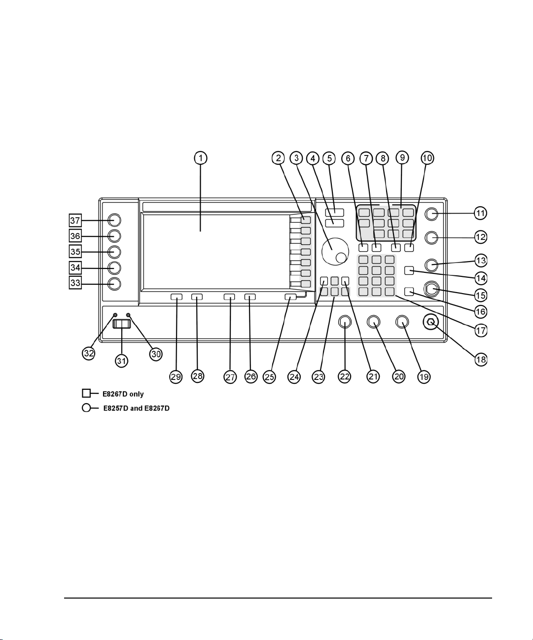
This section describes each item on the PSG front panel. Figure 1-1 shows an E8267D front panel,
which includes all items available on the E8257D as well.
Figure 1-1 Standard E8267D Front Panel Diagram
1. Display 10. Help 19. SYNC OUT 28. Local
2. Softkeys 11. EXT 1 INPUT 20. VIDEO OUT 29. Preset
3. Knob 12. EXT 2 INPUT 21. Incr Set 30. Line Power LED
4. Amplitude 13. LF OUTPUT 22. GATE/ PULSE/ TRIGGER INPUT 31. LINE
5. Frequency 14. Mod On/Off 23. Arrow Keys 32. Standby LED
6. Save 15. ALC INPUT 24. Hold 33. SYMBOL SYNC
7. R e cal l 16. RF On/Off 25. Return 34. DATA CLOCK
8. Trigger 17. Numeric Keypad 26. Contrast Decrease 35. DATA
9. MENUS 18. RF OUTPUT 27. Contrast Increase 36. Q Input
37. I Input
Chapter 1 7
Page 22

Signal Generator Overview
Front Panel
1. Display
The LCD screen provides information on the current function. Information can include status
indicators, frequency and amplitude settings, and error messages. Softkeys labels are located on the
right- hand side of the display. For more detail on the front panel display, see “Front Panel Display”
on page 14.
2. Softkeys
Softkeys activate the displayed function to the left of each key.
3. Knob
Use the knob to increase or decrease a numeric value, change a highlighted digit or character, or step
through lists or select items in a row.
4. Amplitude
Pressing this hardkey makes amplitude the active function. You can change the output amplitude or
use the menus to configure amplitude attributes such as power search, user flatness, and leveling
mode.
5. Frequency
Pressing this hardkey makes frequency the active function. You can change the output frequency or
use the menus to configure frequency attributes such as frequency multiplier, offset, and reference.
6. Save
Pressing this hardkey displays a menu of choices that enable you to save data in the instrument state
register. The instrument state register is a section of memory divided into 10 sequences (numbered 0
through 9), each containing 100 registers (numbered 00 through 99). It is used to store and recall
frequency, amplitude, and modulation settings.
Save hardkey provides a quick alternative to reconfiguring the signal generator through the front
The
panel or SCPI commands when switching between different signal configurations. Once an instrument
state has been saved, all of the frequency, amplitude, and modulation settings can be recalled with
Recall hardkey. For more information on saving and recalling instrument states, refer to “Using the
the
Instrument State Registers” on page 57.
7. Recall
This key restores an instrument state saved in a memory register. To recall an instrument state, press
and enter the desired sequence number and register number. To save a state, use the Save
Recall
hardkey. For more information on saving and recalling instrument states, refer to “Using the
Instrument State Registers” on page 57.
8 Chapter 1
Page 23

Signal Generator Overview
Front Panel
8. Trigger
This key initiates an immediate trigger event for a function such as a list, step, or ramp sweep
(Option 007 only). Before this hardkey can be used to initiate a trigger event, the trigger mode must
be set to
Trigger Key. For example: press the Sweep/List hardkey, then one of the following sequences
of softkeys:
More (1 of 2) > Sweep Trigger > Trigger Key
•
• More (1 of 2) > Point Trigger > Trigger Key
9. MENUS
These keys open softkey menus for configuring various functions. For descriptions, see the
E8257D/67D PSG Signal Generators Key Reference.
Table 1-2 Hardkeys in Front Panel MENUS Group
E8257D PSG Analog E8267D PSG Vector
AM
Sweep/List
FM/ΦM
Utility
Pulse
LF Out
Mode
Mux
AM
Sweep/List
Mode Setup
Aux Fctn
FM/ΦM
Utility
I/Q
Pulse
LF Out
NOTE Some menus are optional. Refer to “Options” on page 4 for more information.
10. Help
Pressing this hardkey causes a short description of any hardkey or softkey to be displayed and, in
most cases, a listing of related remote- operation SCPI commands. There are two help modes available
on the signal generator: single and continuous. The single mode is the factory preset condition.
Toggle between single and continuous mode by pressing
Single Cont
.
Utility > Instrument Info/Help Mode > Help Mode
• In single mode, help text is provided for the next key you press without activating the key’s
function. Any key pressed afterward exits the help mode and its function is activated.
• In continuous mode, help text is provided for each subsequent key press until you press the Help
hardkey again or change to single mode. In addition, each key is active, meaning that the key
function is executed (except for the Preset key).
11. EXT 1 INPUT
This female BNC input connector (functional only with Options UNT, UNU, or UNW) accepts a ±1Vp
signal for AM, FM, and ΦM. For these modulations, ±1V
When ac- coupled inputs are selected for AM, FM, or ΦM and the peak input voltage differs from 1 V
by more than 3 percent, the HI/LO display annunciators light. The input impedance is selectable as
either 50 or 600 ohms; the damage levels are 5 V
rms
1EM, this connector is located on the rear panel.
produces the indicated deviation or depth.
p
and 10 Vp. On signal generators with Option
p
Chapter 1 9
Page 24

Signal Generator Overview
Front Panel
12. EXT 2 INPUT
This female BNC input connector (functional only with Options UNT, UNU, or UNW) accepts a ±1Vp
signal for AM, FM, and ΦM. With AM, FM, or ΦM, ±1V
produces the indicated deviation or depth.
p
When ac- coupled inputs are selected for AM, FM, or ΦM and the peak input voltage differs from 1 V
by more than 3 percent, the HI/LO annunciators light on the display. The input impedance is
selectable as either 50 or 600 ohms and damage levels are 5 V
and 10 Vp. On signal generators
rms
with Option 1EM, this connector is located on the rear panel.
13. LF OUTPUT
This female BNC output connector (functional only with Option UNT) outputs modulation signals
generated by the low frequency (LF) source function generator. This output is capable of driving
(nominal) into a 50 ohm load. On signal generators with Option 1EM, this connector is located
3V
p
on the rear panel.
14. Mod On/Off
This hardkey (E8267D and E8257D with Options UNT, UNU, or UNW and E8267D only) enables or
disables all active modulation formats (AM, FM, ΦM, Pulse, or I/Q) applied to the output carrier
signal available through the RF OUTPUT connector. This hardkey does not set up or activate an AM,
FM, ΦM, Pulse, or I/Q format; each modulation format must still be set up and activated (for
example,
is enabled. The MOD ON/OFF annunciator indicates whether active modulation formats have been
enabled or disabled with the
AM > AM On) or nothing is applied to the output carrier signal when the Mod On/Off hardkey
Mod On/Off hardkey.
p
15. ALC INPUT
This female BNC input connector is used for negative external detector leveling. This connector
accepts an input of −0.2 mV to −0.5 V. The nominal input impedance is 120 kohms and the damage
level is ±15 V. On signal generators with Option 1EM, this connector is located on the rear panel.
16. RF On/Off
Pressing this hardkey toggles the operating state of the RF signal present at the RF OUTPUT
connector. Although you can set up and enable various frequency, power, and modulation states, the
RF and microwave output signal is not present at the RF OUTPUT connector until
On. The
RF On/Off annunciator is always visible in the display to indicate whether the RF is turned
RF On/Off is set to
on or off.
17. Numeric Keypad
The numeric keypad consists of the 0 through 9 hardkeys, a decimal point hardkey, and a backspace
hardkey ( ). The backspace hardkey enables you to backspace or alternate between a positive
and a negative value. When specifying a negative numeric value, the negative sign must be entered
prior to entering the numeric value.
10 Chapter 1
Page 25

Signal Generator Overview
Front Panel
18. RF OUTPUT
This connector outputs RF and microwave signals. The nominal output impedance is 50 ohms. The
reverse-power damage levels are 0 Vdc, 0.5 watts nominal. On signal generators with Option 1EM,
this connector is located on the rear panel. The connector type varies according to frequency option.
19. SYNC OUT
This female BNC output connector (functional only with Options UNU or UNW) outputs a
synchronizing TTL- compatible pulse signal that is nominally 50 ns wide during internal and triggered
pulse modulation. The nominal source impedance is 50 ohms. On signal generators with Option 1EM,
this connector is located on the rear panel.
20. VIDEO OUT
This female BNC output connector (functional only with Options UNU or UNW) outputs a TTL- level
compatible pulse signal that follows the output envelope in all pulse modes. The nominal source
impedance is 50 ohms. On signal generators with Option 1EM, this connector is located on the rear
panel.
21. Incr Set
This hardkey enables you to set the increment value of the current active function. The increment
value of the current active function appears in the active entry area of the display. Use the numeric
keypad, arrow hardkeys, or the knob to adjust the increment value.
22. GATE/ PULSE/ TRIGGER INPUT
This female BNC input connector (functional only with Options UNU or UNW) accepts an externally
supplied pulse signal for use as a pulse or trigger input. With pulse modulation, +1 V is on and 0 V
is off (trigger threshold of 0.5 V with a hysteresis of 10 percent; so 0.6 V would be on and 0.4 V
would be off). The damage levels are ±5V
On signal generators with Option 1EM, this connector is located on the rear panel.
and 10 Vp. The nominal input impedance is 50 ohms.
rms
23. Arrow Keys
These up and down arrow hardkeys are used to increase or decrease a numeric value, step through
displayed lists, or to select items in a row of a displayed list. Individual digits or characters may be
highlighted using the left and right arrow hardkeys. Once an individual digit or character is
highlighted, its value can be changed using the up and down arrow hardkeys.
24. Hold
Pressing this hardkey blanks the softkey label area and text areas on the display. Softkeys, arrow
hardkeys, the knob, the numeric keypad, and the
pressed.
Chapter 1 11
Incr Set hardkey have no effect once this hardkey is
Page 26

Signal Generator Overview
Front Panel
25. Return
Pressing this hardkey displays the previous softkey menu. It enables you to step back through the
menus until you reach the first menu you selected.
26. Contrast Decrease
Pressing this hardkey causes the display background to darken.
27. Contrast Increase
Pressing this hardkey causes the display background to lighten.
28. Local
Pressing this hardkey deactivates remote operation and returns the signal generator to front-panel
control.
29. Preset
Pressing this hardkey sets the signal generator to a known state (factory or user- defined).
30. Line Power LED
This green LED indicates when the signal generator power switch is set to the on position.
31. LINE
In the on position, this switch activates full power to the signal generator; in standby, it deactivates
all signal generator functions. In standby, the signal generator remains connected to the line power
and power is supplied to some internal circuits.
32. Standby LED
This yellow LED indicates when the signal generator power switch is set to the standby condition.
33. SYMBOL SYNC
This female BNC input connector is CMOS- compatible and accepts an externally supplied symbol sync
signal for use with the internal baseband generator (Option 601/602). The expected input is a 3.3 V
CMOS bit clock signal (which is also TTL compatible). SYMBOL SYNC might occur once per symbol or
be a single one- bit- wide pulse that is used to synchronize the first bit of the first symbol. The
maximum clock rate is 50 MHz. The damage levels are > +5.5 V and < −0.5V. The nominal input
impedance is not definable. SYMBOL SYNC can be used in two modes:
• When used as a symbol sync in conjunction with a data clock, the signal must be high during the
first data bit of the symbol. The signal must be valid during the falling edge of the data clock
signal and may be a single pulse or continuous.
12 Chapter 1
Page 27

Signal Generator Overview
Front Panel
• When the SYMBOL SYNC itself is used as the (symbol) clock, the CMOS falling edge is used to
clock the DATA signal.
On signal generators with Option 1EM, this connector is located on the rear panel.
34. DATA CLOCK
This female BNC input connector is CMOS compatible and accepts an externally supplied data- clock
input signal to synchronize serial data for use with the internal baseband generator (Option 601/602).
The expected input is a 3.3 V CMOS bit clock signal (which is also TTL compatible) where the rising
edge is aligned with the beginning data bit. The falling edge is used to clock the DATA and SYMBOL
SYNC signals. The maximum clock rate is 50 MHz. The damage levels are > +5.5 V and < −0.5V. The
nominal input impedance is not definable. On signal generators with Option 1EM, this connector is
located on the rear panel.
35. DATA
This female BNC input connector (Options 601/602 only) is CMOS compatible and accepts an
externally supplied serial data input for digital modulation applications. The expected input is a 3.3 V
CMOS signal (which is also TTL compatible) where a CMOS high = a data 1 and a CMOS low = a data
0. The maximum input data rate is 50 Mb/s. The data must be valid on the falling edges of the data
clock (normal mode) or the on the falling edges of the symbol sync (symbol mode). The damage levels
are > +5.5 and < −0.5V. The nominal input impedance is not definable. On signal generators with
Option 1EM, this connector is located on the rear panel.
36. Q Input
This female BNC input connector (E8267D only) accepts the quadrature- phase (Q) component of an
externally supplied, analog, I/Q modulation. The in- phase (I) component is supplied through the I
INPUT. The signal level is = 0.5 V
impedance is 50 or 600 ohms. The damage level is 1 V
the I and Q input connectors, press
Ext 600 Ohm. On signal generators with Option 1EM, these connectors are located on the rear panel.
Mux > I/Q Source 1 or I/Q Source 2 and then select either Ext 50 Ohm or
for a calibrated output level. The nominal input
rms
and 10 V
rms
. To activate signals applied to
peak
37. I Input
This female BNC input connector (E8267D only) accepts the in- phase (I) component of an externally
supplied, analog, I/Q modulation. The quadrature- phase (Q) component is supplied through the Q
INPUT. The signal level is = 0.5 V
impedance is 50 or 600 ohms. The damage level is 1 V
the I and Q input connectors, press
Ext 600 Ohm. On signal generators with Option 1EM, these connectors are located on the rear panel.
Chapter 1 13
Mux > I/Q Source 1 or I/Q Source 2 and then select either Ext 50 Ohm or
for a calibrated output level. The nominal input
rms
and 10 V
rms
. To activate signals applied to
peak
Page 28
Signal Generator Overview
Front Panel Display
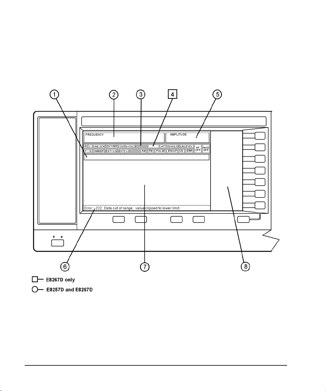
Front Panel Display
Figure 1-2 shows the various regions of the PSG display. This section describes each region.
Figure 1-2 Front Panel Display Diagram
1. Active Entry Area 5. Amplitude Area
2. Frequency Area 6. Error Message Area
3. Annunciators 7. Text Area
4. Digital Modulation Annunciators 8. Softkey Label Area
14 Chapter 1
Page 29

Signal Generator Overview
Front Panel Display
1. Active Entry Area
The current active function is shown in this area. For example, if frequency is the active function, the
current frequency setting will be displayed here. If the current active function has an increment value
associated with it, that value is also displayed.
2. Frequency Area
The current frequency setting is shown in this portion of the display. Indicators are also displayed in
this area when the frequency offset or multiplier is used, the frequency reference mode is turned on,
or a source module is enabled.
3. Annunciators
The display annunciators show the status of some of the signal generator functions and indicate any
error conditions. An annunciator position may be used by more than one function. This does not
create a problem, because only one function that shares an annunciator position can be active at a
time.
ΦM This annunciator (Option UNT only) appears when phase modulation is on. If
ALC OFF This annunciator appears when the ALC circuit is disabled. A second annunciator,
AM This annunciator (Option UNT only) appears when amplitude modulation is on.
ARMED This annunciator appears when a sweep has been initiated and the signal
ATTEN HOLD This annunciator (E8267D or E8257D with Option 1E1 only) appears when the
DIG BUS This annunciator (Options 003/004 only) appears when the digital bus is active,
ENVLP This annunciator appears if a burst condition exists, such as when marker 2 is set
ERR This annunciator appears when an error message is in the error queue. This
EXT This annunciator appears when external leveling is on.
EXT1 LO/HI This annunciator (Options UNT, UNU, or UNW only) appears as either EXT1 LO or
EXT2 LO/HI This annunciator (Options UNT, UNU, or UNW only) is displayed as either
frequency modulation is on, the FM annunciator replaces ΦM.
UNLEVEL, appears in the same position if the ALC is enabled and cannot maintain
the output level.
generator is waiting for the sweep trigger event.
attenuator hold function is on. When this function is on, the attenuator is held at
its current setting.
and the internal oven reference oscillator is not cold (OVEN COLD appears in this
same location).
to enable RF blanking in the Dual ARB format.
annunciator does not turn off until you either view all the error messages or
cleared the error queue. To access error messages, press
EXT1 HI, when the ac- coupled signal to the EXT 1 INPUT is < 0.97 V
>1.03V
.
p
Utility > Error Info.
or
p
EXT2 LO or EXT2 HI. This annunciator appears when the ac- coupled signal to the
EXT 2 INPUT is < 0.97 Vp or > 1.03 Vp.
Chapter 1 15
Page 30

Signal Generator Overview
Front Panel Display
EXT REF This annunciator appears when an external frequency reference is applied.
FM This annunciator (Option UNT only) appears when frequency modulation is turned
on. If phase modulation is turned on, the ΦM annunciator will replace FM.
I/Q This annunciator (E8267D only) appears when I/Q modulation is turned on.
L This annunciator appears when the signal generator is in listener mode and is
receiving information or commands over the RS- 232, GPIB, or VXI- 11 LAN
interface.
MOD ON/OFF This annunciator (E8267D and E8257D with Options UNT, UNU, or UNW only)
indicates whether active modulation formats have been enabled or disabled.
Pressing the
Mod On/Off hardkey enables or disables all active modulation formats
(AM, FM, ΦM, Pulse, or I/Q) that are applied to the output carrier signal available
through the RF OUTPUT connector. The
Mod On/Off hardkey does not set up or
activate an AM, FM, ΦM, Pulse, or I/Q format; each individual modulation format
must still be set up and activated (for example,
applied to the output carrier signal when the
AM > AM On) or nothing will be
Mod On/Off hardkey is enabled.
OVEN COLD This annunciator (Option UNR/UNX only) appears when the temperature of the
internal oven reference oscillator has dropped below an acceptable level. When
this annunciator is on, frequency accuracy is degraded. This condition should
occur for several minutes after the signal generator is first connected to line
power.
PULSE This annunciator (Options UNU or UNW only) appears when pulse modulation is
on.
R This annunciator appears when the signal generator is remotely controlled over
the GPIB, RS- 232, or VXI- 11/Sockets LAN interface (TELNET operation does not
activate the R annunciator). When the R annunciator is on, the front panel keys
are disabled, except for the Local key and the line power switch. For information
on remote operation, refer to the Programming Guide.
RF ON/OFF This annunciator indicates when the RF or microwave signal is present (RF ON) or
not present (RF OFF) at the RF OUTPUT. Either condition of this annunciator is
always visible in the display.
S This annunciator appears when the signal generator has generated a service
request (SRQ) over the RS- 232, GPIB, or VXI- 11 LAN interface.
SWEEP This annunciator appears when the signal generator is in list, step, or ramp sweep
mode (ramp sweep is available with Option 007 only). List mode is when the
signal generator can jump from point to point in a list (hop list); the list is
traversed in ascending or descending order. The list can be a frequency list, a
power level list, or both. Step mode is when a start, stop, and step value
(frequency or power level) are defined and the signal generator produces signals
that start at the start value and increment by the step value until it reaches the
stop value. Ramp sweep mode (Option 007 only) is when a start and stop value
(frequency or power level) are defined and the signal generator produces signals
that start at the start value and produce a continuous output until it reaches the
stop value.
T This annunciator appears when the signal generator is in talker mode and is
transmitting information over the GPIB, RS- 232, or VXI- 11 LAN interface.
16 Chapter 1
Page 31

Signal Generator Overview
Front Panel Display
UNLEVEL This annunciator appears when the signal generator is unable to maintain the
UNLOCK This annunciator appears when any of the phase locked loops are unable to
correct output level. The UNLEVEL annunciator is not necessarily an indication of
instrument failure. Unleveled conditions can occur during normal operation. A
second annunciator, ALC OFF, will appear in the same position when the ALC
circuit is disabled.
maintain phase lock. You can determine which loop is unlocked by examining the
error messages.
4. Digital Modulation Annunciators
All digital modulation annunciators (E8267D with Option 601/602 only) appear in this location. These
annunciators appear only when the modulation is active, and only one digital modulation can be
active at any given time.
ARB Dual Arbitrary Waveform Generator M-TONE Multitone Waveform Generator
CUSTOM Custom Real Time I/Q Baseband T-TONE Two- Tone Waveform Generator
DIGMOD Custom Arb Waveform Generator
5. Amplitude Area
The current output power level setting is shown in this portion of the display. Indicators are also
displayed in this area when amplitude offset is used, amplitude reference mode is turned on, external
leveling mode is enabled, a source module is enabled, and when user flatness is enabled.
6. Error Message Area
Abbreviated error messages are reported in this space. When multiple error messages occur, only the
most recent message remains displayed. Reported error messages with details can be viewed by
pressing
Utility > Error Info.
7. Text Area
This text area of the display:
• shows signal generator status information, such as the modulation status, sweep lists, and file
catalogs
• displays the tables
• enables you to perform functions such as managing information, entering information, and
displaying or deleting files
8. Softkey Label Area
The labels in this area define the function of the softkeys located immediately to the right of the
label. The softkey label may change depending upon the function selected.
Chapter 1 17
Page 32
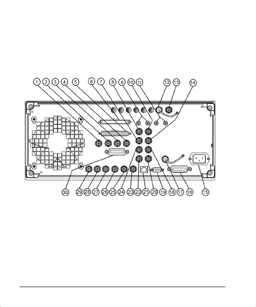
Signal Generator Overview
Rear Panel
Rear Panel
This section describes each item on the PSG rear panel. Four consecutive drawings show the
standard and Option 1EM rear panels for the E8267D and the E8257D. (Option 1EM moves all front
panel connectors to the real panel.)
Figure 1-3 Standard E8267D Rear Panel
1. EVENT 1 11. WIDEBAND Q INPUTS 21. LAN
2. EVENT 2 12. COH CARRIER 22. 10 MHz OUT
3. PATTERN TRIG IN 13. 1 GHz REF OUT (Serial Prefixes
4. BURST GATE IN 14. Q- bar OUT 24. BASEBAND GEN CLK IN
5. AUXILIARY I/O 15. AC Power Receptacle 25. Z- AXIS BLANK/MKRS
6. DIGITAL BUS 16. GPIB 26. SWEEP OUT
7. Q OUT 17. 10 MHz EFC 27. TRIGGER OUT
8. I OUT 18. ALC HOLD (Serial Prefixes
9. WIDEBAND I INPUTS 19. AUXILIARY INTERFACE 29. SOURCE SETTLED
10. I- bar OUT 20. 10 MHz IN 30. SOURCE MODULE INTERFACE
>=US4646/MY4646)
>=US4722/MY4722)
23. STOP SWEEP IN/OUT
28. TRIGGER IN
18 Chapter 1
Page 33

Figure 1-4 E8267D Option 1EM Rear Panel
Signal Generator Overview
Rear Panel
1. EVENT 1 16. GPIB 31. RF OUT
2. EVENT 2 17. 10 MHz EFC 32. EXT 1
3. PATTERN TRIG IN 18. ALC HOLD (Serial Prefixes >=US4722/MY4722) 33. EXT 2
4. BURST GATE IN 19. AUXILIARY INTERFACE 34. PULSE SYNC OUT
5. AUXILIARY I/O 20. 10 MHz IN 35. PULSE VIDEO OUT
6. DIGITAL BUS 21. LAN 36. PULSE/TRIG GATE INPUT
7. Q OUT 22. 10 MHz OUT 37. ALC INPUT
8. I OUT 23. STOP SWEEP IN/OUT 38. DATA CLOCK
9. WIDEBAND I INPUTS 24. BASEBAND GEN CLK IN 39. I IN
10. I- bar OUT 25. Z- AXIS BLANK/MKRS 40. SYMBOL SYNC
11. WIDEBAND Q INPUTS 26. SWEEP OUT 42. DATA
12. COH CARRIER 27. TRIGGER OUT 41. Q IN
13. 1 GHz REF OUT (Serial Prefixes
>=US4646/MY4646)
14. Q- bar OUT 29. SOURCE SETTLED
15. AC Power Receptacle 30. SOURCE MODULE INTERFACE
28. TRIGGER IN 43. LF OUT
Chapter 1 19
Page 34

Signal Generator Overview
Rear Panel
Figure 1-5 Standard E8257D Rear Panel
5. AUXI LI ARY I/ O 19. AUXILIA RY INTER FACE 25. Z- AXIS BL ANK/ MK RS
12. COH CARRIER 20. 10 MHz IN 26. SWEEP OUT
15. AC Power Receptacle 21. LAN 27. TRIGGER OUT
16. GPIB 22. 10 MHz OUT 28. TRIGGER IN
17. 10 MHz EFC 23. STOP SWEEP IN/OUT 29. SOURCE SETTLED
20 Chapter 1
Page 35

Figure 1-6 E8257D Option 1EM Rear Panel
Signal Generator Overview
Rear Panel
5. AUXILIARY I/O 22. 10 MHz OUT 33. EXT 2
12. COH CARRIER 23. STOP SWEEP IN/OUT 34. PULSE SYNC OUT
15. AC Power Receptacle 25. Z- AXIS BLANK/MKRS 35. PULSE VIDEO OUT
16. GPIB 26. SWEEP OUT 36. PULSE/TRIG GATE INPUT
17. 10 MHz EFC 27. TRIGGER OUT 37. ALC INPUT
19. AUXILIARY INTERFACE 28. TRIGGER IN 43. LF OUT
20. 10 MHz IN 31. RF OUT
21. LAN 32. EXT 1
Chapter 1 21
Page 36

Signal Generator Overview
Rear Panel
1. EVENT 1
This female BNC connector is used with an internal baseband generator (Option 601/602). On signal
generators without Option 601/602, this female BNC connector is non- functional.
In real- time mode, the EVENT 1 connector outputs a pattern or frame synchronization pulse for
triggering or gating external equipment. It may be set to start at the beginning of a pattern, frame, or
timeslot and is adjustable to within ± one timeslot with one bit resolution.
In arbitrary waveform mode, the EVENT 1 connector outputs a timing signal generated by Marker 1.
A marker (3.3 V CMOS high for both positive and negative polarity) is output on the EVENT 1
connector whenever a Marker 1 is turned on in the waveform.
The reverse damage levels for this connector are > +8 V and < −4 V. The nominal output impedance
is not defined.
2. EVENT 2
This female BNC connector is used with an internal baseband generator (Option 601/602). On signal
generators without Option 601/602, this female BNC connector is non- functional.
In real- time mode, the EVENT 2 connector outputs a data enable signal for gating external
equipment. This is applicable when external data is clocked into internally generated timeslots. Data
is enabled when the signal is low.
In arbitrary waveform mode, the EVENT 2 connector outputs a timing signal generated by Marker 2.
A marker (3.3 V CMOS high for both positive and negative polarity) is output on the EVENT 2
connector whenever a Marker 2 is turned on in the waveform.
The reverse damage levels for this connector are > +8 V and < −4 V. The nominal output impedance
is not defined.
3. PATTERN TRIG IN
This female BNC connector is used with an internal baseband generator (Option 601/602). On signal
generators without Option 601/602, this female BNC connector is non- functional. This connector
accepts a signal that triggers an internal pattern or frame generator to start a single- pattern output.
Minimum pulse width is 100 ns. Damage levels are > +5.5 V and < −0.5 V. The nominal input
impedance is not defined.
4. BURST GATE IN
This female BNC connector is used with an internal baseband generator (Option 601/602). On signal
generators without Option 601/602, this connector is non-functional. This connector accepts a 3- volt
CMOS input signal for gating burst power. Burst gating is used when you are externally supplying
data and clock information.
The input signal must be synchronized with the external data input that will be output during the
burst. The burst power envelope and modulated data are internally delayed and re-synchronized. The
input signal must be CMOS high for normal burst RF power or CW RF output power and CMOS low
for RF off. Damage levels are > +5.5 V and < −0.5 V. The nominal input impedance is not defined.
22 Chapter 1
Page 37

5. AUXILIARY I/O
ALT PWR IN: Used with an internal baseband
generator. This pin accepts a CMOS signal for
synchronization of external data and alternate power
signal timing. Damage levels are > +8 V and < −4V.
View looking into
rear panel connector
DATA CLK OUT: Used with an internal baseband
generator. This pin relays a CMOS bit clock signal for
synchronizing serial data.
DATA OUT: Used with an internal baseband generator.
This pin outputs data (CMOS) from the internal data
generator or the externally supplied signal at data input.
EVENT 3: Used with an internal baseband generator. In arbitrary waveform mode,
this pin outputs a timing signal generated by Marker 3. A marker (3.3 V CMOS
high for both positive and negative polarity) is output on this pin when a Marker 3 is
turned on in the waveform. Reverse damage levels: > +8 V and < −4V.
P ATT TRIG IN 2: Acce pts a signal that triggers an
internal pattern or frame generator to start single
pattern output. Minimum pulse width: 100 ns.
Damage levels: > +5.5 V and < −0.5 V.
SYM SYNC OUT: Used with an internal baseband
generator. This pin outputs the CMOS symbol clock for
symbol synchronization, one data clock period wide.
EVENT 4: Used with an internal baseband generator . In arbit rary
waveform mode, this pin outputs a timing signal generated by
Marker 4. A marker (3.3V CMOS high for both positive and
negative polarity) is output on this pin when a Marker 4 is turned
on in the waveform. Reverse damage levels: > +8 V and < −4V.
This female 37-pin connector is active only on instruments with an internal baseband generator
(Option 601/602); on signal generators without Option 601/602, this connector is non- functional. This
connector provides access to the inputs and outputs described in the following figure.
Figure 1-7 Auxiliary I/O Connector (Female 37-Pin)
Signal Generator Overview
Rear Panel
Chapter 1 23
Page 38

Signal Generator Overview
Rear Panel
6. DIGITAL BUS
This is a proprietary bus used for Agilent Baseband Studio products, which require an E8267D with
Options 003/004 and 601/602. This connector is not operational for general- purpose customer use.
Signals are present only when a Baseband Studio option is installed (for details, refer to
http://www.agilent.com/find/basebandstudio). The DIG BUS annunciator appears on the display when
the Digital Bus is active (and the internal oven reference oscillator is not cold—OVEN COLD appears in
this same location).
7. Q OUT
This female BNC connector (E8267D only) is used with an internal baseband generator
(Option 601/602) to output the analog, quadrature-phase component of I/Q modulation. On signal
generators without Option 601/602, this female BNC connector is used to output the
quadrature-phase component of an external I/Q modulation that has been fed into the Q input
connector. The nominal output impedance of the Q OUT connector is 50 ohms, dc- coupled.
8. I OUT
This female BNC connector (E8267D only) is used with an internal baseband generator
(Option 601/602) to output the analog, in- phase component of I/Q modulation. On signal generators
without Option 601/602, this female BNC connector is used to output the in-phase component of an
external I/Q modulation that has been fed into the I input connector. The nominal output impedance
of the I OUT connector is 50 ohms, dc- coupled.
9. WIDEBAND I INPUTS
These female SMA connectors: I IN (+) and I- bar IN (−) (Option 016 only) are used with differential
wideband external I/Q inputs. They accept wideband AM and allow direct high–bandwidth analog
inputs to the I/Q modulator in the 3.2−44 GHz range (frequency limit is dependant on the option).
This input is not calibrated. The recommended input power level is −1 dBm with a +/− 1 VDC input
voltage. The nominal impedance for this connector is 50 ohms.
The signal generator uses lowside mixing in the 20–28.5 GHz frequency range (Options 532 and 544),
which reverses the phase relationship for I and Q signals. For internally generated I/Q signals the
signal generator’s firmware compensates for this. However, for wideband external I/Q inputs
(Option 016) there is no compensation and the I and Q inputs at the rear panel must be reversed to
maintain the correct phase relationships in this frequency band. Refer to the Data Sheet and to the
A37 Upconverter description in the Service Guide for more information.
For instruments with Option 015 (discontinued), single- ended wideband I/Q, there is a single BNC I
input. The recommended power level at this input connector is 0 dBM.
24 Chapter 1
Page 39

Signal Generator Overview
Rear Panel
10. I-bar OUT
This female BNC connector (E8267D only) is used with an internal baseband generator
(Option 601/602) to output the complement of the analog, in- phase component of I/Q modulation. On
signal generators without Option 601/602, this female BNC connector is used to output the
complement of the in- phase component of an external I/Q modulation that has been fed into the
Iinput connector.
I- bar OUT is used in conjunction with I OUT to provide a balanced baseband stimulus. Balanced
signals are signals present in two separate conductors that are symmetrical relative to ground and
are opposite in polarity (180 degrees out of phase). The nominal output impedance of the I- bar OUT
connector is 50 ohms, dc- coupled.
11. WIDEBAND Q INPUTS
These female SMA connectors: Q IN (+) and Q- bar IN (−) (Option 016 only) are used with differential
wideband external I/Q inputs. They accept wideband AM and allow direct high–bandwidth analog
inputs to the I/Q modulator in the 3.2−44 GHz range (frequency limit is dependant on the option).
This input is not calibrated. The recommended input power level is −1 dBm with a +/− 1 VDC input
voltage. The nominal impedance for this connector is 50 ohms.
The signal generator uses lowside mixing in the 20–28.5 GHz frequency range (Options 532 and 544),
which reverses the phase relationship for I and Q signals. For internally generated I/Q signals the
signal generator’s firmware compensates for this. However, for wideband external I/Q inputs
(Option 016) there is no compensation and the I and Q inputs at the rear panel must be reversed to
maintain the correct phase relationships in this frequency band. Refer to the Data Sheet and to the
A37 Upconverter description in the Service Guide for more information.
For instruments with Option 015 (discontinued), single- ended wideband I/Q, there is a single BNC Q
input. The recommended power level at this input connector is 0 dBM.
12. COH CARRIER
This female SMA connector (Option UNT only) outputs an RF signal that is phase coherent with the
signal generator carrier. The coherent carrier connector outputs RF that is not modulated with AM,
pulse, or I/Q modulation, but is modulated with FM or ΦM (when FM or ΦM are on).
The output power is nominally 0 dBm. The output frequency range is from 249.99900001 MHz to
3.2 GHz; this output is not useful for output frequencies > 3.2 GHz. If the RF output frequency is
below 249.99900001 MHz, the coherent carrier output signal will have the following frequency:
Frequency of coherent carrier = (1E9 − Frequency of RF output) in Hz.
Damage levels are 20 Vdc and 13 dBm reverse RF power. The nominal output impedance of this
connector is 50 ohms.
13. 1 GHz REF OUT (Serial Prefixes >=US4646/MY4646)
This female SMA connector (Option UNX only) provides a 1 GHz output that is 100 times the
frequency of the internal or external 10 MHz reference. The nominal output level is 7 dBM. The
nominal output impedance is 50 ohms. When not in use, this connector must be terminated with a
50 ohm load.
Chapter 1 25
Page 40

Signal Generator Overview
Rear Panel
14. Q-bar OUT
This female BNC connector (E8267D only) can be used with an internal baseband generator
(Option 601/602) to output the complement of the analog, quadrature- phase component of I/Q
modulation. On signal generators without Option 601/602, this female BNC connector can be used to
output the complement of the quadrature- phase component of an external I/Q modulation that has
been fed into the Q input connector.
Q- bar OUT is used in conjunction with Q OUT to provide a balanced baseband stimulus. Balanced
signals are signals present in two separate conductors that are symmetrical relative to ground and
are opposite in polarity (180 degrees out of phase). The nominal output impedance of the Q- bar OUT
connector is 50 ohms, dc- coupled.
15. AC Power Receptacle
The ac line voltage is connected here. The power cord receptacle accepts a three- pronged power cable
that is shipped with the signal generator.
16. GPIB
This GPIB interface allows listen and talk capability with compatible IEEE 488.2 devices.
17. 10 MHz EFC
This female BNC input connector (Options UNR/UNX only) accepts an external dc voltage, ranging
from −5 V to +5 V, for electronic frequency control (EFC) of the internal 10 MHz reference oscillator.
This voltage inversely tunes the oscillator about its center frequency (approximately −0.0025 ppm/V).
The nominal input impedance is greater than 1 Mohms. When not in use, this connector should be
shorted using the supplied shorting cap to assure a stable operating frequency.
18. ALC HOLD (Serial Prefixes >=US4722/MY4722)
This female BNC connector (E8267D only) is a TTL- compatible input that controls ALC action with
bursted I/Q signals from an arbitrary waveform generator (AWG). A high signal allows the ALC to
track the RF signal and maintain constant RF output level as the I/Q inputs vary. A low input signal
allows the ALC to be held for a brief time (less than 1 second) and not track the RF signal. When
driving the external I/Q inputs from an external arbitrary waveform generator supplying a bursted
waveform, the ALC Hold line should be driven from a marker output from the AWG that is high when
the bursted signal is at the proper level and low when the bursted signal is not at the proper level
Damage levels are > 5.5 V and < −0.5 V.
26 Chapter 1
Page 41

Signal Generator Overview
View looking into
rear panel connector
Rear Panel
19. AUXILIARY INTERFACE
This 9- pin D- subminiature female connector is an RS- 232 serial port that can be used for serial
communication and Master/Slave source synchronization.
Table 1-3 Auxiliary Interface Connector
Pin Number Signal Description Signal Name
1 No Connection (default operation)/
2 Receive Data RECV
3 Transmit Data XMIT
4 +5V (Default operation)/
5Ground, 0V
6No Connection
7Request to SendRTS
8Clear to SendCTS
9No Connection
Retrace (Master/Slave operation)
Sweep Stop (Master/Slave operation)
Figure 1-8
20. 10 MHz IN
This female BNC connector accepts an external timebase reference input signal level of > −3dBm.
The reference must be 1, 2, 2.5, 5, or 10 MHz, within ±1 ppm. The signal generator detects when a
valid reference signal is present at this connector and automatically switches from internal to
external reference operation.
For Option UNR/UNX or instruments with serial prefixes >
accepts a signal with a nominal input level of 5 ±5 dBm. The external frequency reference must be
10 MHz, within ±1 ppm.
The nominal input impedance is 50 ohms with a damage level of ≥ 10 dBm.
US4805/MY4805, this BNC connector
21. LAN
This LAN interface allows ethernet local area network communication through a 10Base- T LAN cable.
The yellow LED on the interface illuminates when data transmission (transfer/receive) is present. The
green LED illuminates when there is a delay in data transmission or no data transmission is present.
Chapter 1 27
Page 42

Signal Generator Overview
Rear Panel
22. 10 MHz OUT
This female BNC connector outputs a nominal signal level of > +4 dBm and has an output impedance
of 50 ohms. The accuracy is determined by the timebase used.
23. STOP SWEEP IN/OUT
This female BNC connector (Option 007 only) provides an open- collector, TTL- compatible
input/output signal that is used during ramp sweep operation. It provides low-level (nominally 0 V)
output during sweep retrace and band-cross intervals. It provides high- level (nominally +5 V) output
during the forward portion of the sweep. Sweep stops when this input/output connector is grounded
externally. When operating as an input, the nominal impedance for this connector is less than
10 ohms. When operating as an output, the nominal impedance is approximately 4.2 kohms.
24. BASEBAND GEN CLK IN
This female BNC connector accepts a sine or square wave PECL clock input with a frequency range
of 200 MHz to 400 MHz, resulting in sample rates of 50 MSa/s to 100 MSa/s. The recommended input
level is approximately 1 Vpeak- to- peak for a square wave and 1 dBm to 6 dBm for a sine wave. This
allows baseband generators from multiple signal sources to run off the same clock.
25. Z-AXIS BLANK/MKRS
This female BNC connector (Option 007 only) supplies a +5 V (nominal) level during retrace and
band- switch intervals of a step, list, or ramp sweep. During ramp sweep, this female BNC connector
supplies a –5 V (nominal) level when the RF frequency is at a marker frequency and intensity marker
mode is on. This signal is derived from an operational amplifier output so the load impedance should
be greater than or equal to 5 kohms. This connection is most commonly used to interface with an
Agilent 8757D Scalar Network Analyzer.
26. SWEEP OUT
This female BNC connector outputs a voltage proportional to the RF power or frequency sweep
ranging from 0 V at the start of sweep and goes to +10 V (nominal) at the end of sweep, regardless
of sweep width.
The nominal output impedance is less than 1 ohm and can drive a 2 kohm load.
When connected to an Agilent Technologies 8757D network analyzer, it generates a selectable number
of equally spaced 1 ms, 10 V pulses (nominal) across a ramp (analog) sweep. The number of pulses
can be set from 101 to 1601 by remote control through the 8757D.
28 Chapter 1
Page 43

Signal Generator Overview
Rear Panel
27. TRIGGER OUT
This female BNC connector, in step/list sweep mode, outputs a TTL signal that is high at the start of
a dwell sequence or when waiting for a point trigger in manual sweep mode. The signal is low when
the dwell is over or when a point trigger is received. In ramp sweep mode, the output provides 1601
equally spaced 1 μs pulses (nominal) across a ramp sweep. When using LF Out, the output provides
a 2 μs pulse at the start of an LF sweep. The nominal impedance for this connector is less than
10 ohms.
28. TRIGGER IN
This female BNC connector accepts a 3.3V CMOS signal, which is used for point- to- point triggering in
manual sweep mode, or in a low frequency (LF output) or analog (AM, FM, and ΦM) external sweep
trigger setup. Triggering can occur on either the positive or negative edge of the signal start. The
damage level is ≤ −4V or ≥+10 V. The nominal input impedance for this connector is approximately
4.2 kohms.
29. SOURCE SETTLED
This female BNC connector provides a 3-volt CMOS output trigger, indicating when the signal
generator has settled to a new frequency or power level. A high indicates that the source has not
settled. A low indicates that the source has settled. The nominal output impedance for this connector
is less than 10 ohms.
30. SOURCE MODULE INTERFACE
This interface is used to connect to compatible Agilent Technologies 83550 Series mm- wave source
modules.
31. RF OUT
This connector outputs RF and microwave signals. The nominal output impedance is 50 ohms. The
reverse power damage levels are 0 Vdc, 0.5 watts nominal. On signal generators without Option 1EM,
this connector is located on the front panel. The connector type varies according to frequency option.
32. EXT 1
This female BNC input connector (functional only with Options UNT, UNU, or UNW) accepts a ±1Vp
signal for AM, FM, and ΦM. For these modulations, ±1V
When ac- coupled inputs are selected for AM, FM, or ΦM and the peak input voltage differs from 1 V
by more than 3 percent, the HI/LO display annunciators light. The input impedance is selectable as
either 50 or 600 ohms; the damage levels are 5 V
1EM, this connector is located on the front panel.
Chapter 1 29
rms
produces the indicated deviation or depth.
p
p
and 10 Vp. On signal generators without Option
Page 44

Signal Generator Overview
Rear Panel
33. EXT 2
This female BNC input connector (functional only with Options UNT, UNU, or UNW) accepts a ±1Vp
signal for AM, FM, and ΦM. With AM, FM, or ΦM, ±1V
When ac- coupled inputs are selected for AM, FM, or ΦM and the peak input voltage differs from 1 V
by more than 3 percent, the HI/LO annunciators light on the display. The input impedance is
selectable as either 50 or 600 ohms and damage levels are 5 V
without Option 1EM, this connector is located on the front panel.
produces the indicated deviation or depth.
p
and 10 Vp. On signal generators
rms
p
34. PULSE SYNC OUT
This female BNC output connector (functional only with Options UNU or UNW) outputs a
synchronizing TTL- compatible pulse signal that is nominally 50 ns wide during internal and triggered
pulse modulation. The nominal source impedance is 50 ohms. On signal generators without Option
1EM, this connector is located on the front panel.
35. PULSE VIDEO OUT
This female BNC output connector (functional only with Options UNU or UNW) outputs a TTL- level
compatible pulse signal that follows the output envelope in all pulse modes. The nominal source
impedance is 50 ohms. On signal generators without Option 1EM, this connector is located on the
front rear panel.
36. PULSE/TRIG GATE INPUT
This female BNC input connector (functional only with Options UNU or UNW) accepts an externally
supplied pulse signal for use as a pulse or trigger input. With pulse modulation, +1 V is on and 0 V
is off (trigger threshold of 0.5 V with a hysteresis of 10 percent; so 0.6 V would be on and 0.4 V
would be off). The damage levels are ±5V
On signal generators without Option 1EM, this connector is located on the front panel.
and 10 Vp. The nominal input impedance is 50 ohms.
rms
37. ALC INPUT
This female BNC input connector is used for negative external detector leveling. This connector
accepts an input of −0.2 mV to −0.5 V. The nominal input impedance is 120 kohms and the damage
level is ±15 V. On signal generators without Option 1EM, this connector is located on the front panel.
38. DATA CLOCK
This female BNC input connector (E8267D only) is CMOS compatible and accepts an externally
supplied data clock input signal to synchronize serial data for use with the internal baseband
generator (Option 601/602). The expected input is a 3.3 V CMOS bit clock signal (which is also TTL
compatible) where the rising edge is aligned with the beginning data bit. The falling edge is used to
clock the DATA and SYMBOL SYNC signals. The maximum clock rate is 50 MHz. The damage levels
are > +5.5 V and < −0.5V. The nominal input impedance is not defined. On signal generators without
Option 1EM, this connector located on the front panel.
30 Chapter 1
Page 45

Signal Generator Overview
Rear Panel
39. I IN
This female BNC input connector (E8267D only) accepts the in- phase (I) component an externally
supplied, analog, I/Q modulation. The quadrature- phase (Q) component is supplied through the Q IN
connector. The signal level is = 0.5 V
impedance is 50 or 600 ohms. The damage level is 1 V
the I and Q input connectors, press
Ext 600 Ohm. On signal generators without Option 1EM, this connector is located on the front panel.
Mux > I/Q Source 1 or I/Q Source 2 and then select either Ext 50 Ohm or
for a calibrated output level. The nominal input
rms
and 10 V
rms
. To activate signals applied to
peak
40. SYMBOL SYNC
This female BNC input connector (E8267D only) is CMOS-compatible and accepts an externally
supplied symbol sync signal for use with the internal baseband generator (Option 601/602). The
expected input is a 3.3 V CMOS bit clock signal (which is also TTL compatible). SYMBOL SYNC might
occur once per symbol or be a single one-bit-wide pulse that is used to synchronize the first bit of
the first symbol. The maximum clock rate is 50 MHz. The damage levels are > +5.5 V and < −0.5V.
The nominal input impedance is not defined. SYMBOL SYNC can be used in two modes:
• When used as a symbol sync in conjunction with a data clock, the signal must be high during the
first data bit of the symbol. The signal must be valid during the falling edge of the data clock
signal and may be a single pulse or continuous.
• When the SYMBOL SYNC itself is used as the (symbol) clock, the CMOS falling edge is used to
clock the DATA signal.
On signal generators without Option 1EM, this connector is located on the front panel.
41. Q IN
This female BNC input connector (E8267D only) accepts the quadrature- phase (Q) component an
externally supplied, analog, I/Q modulation. The in- phase (I) component is supplied through the I IN
connector. The signal level is = 0.5 V
impedance is 50 or 600 ohms. The damage level is 1 V
the I and Q input connectors, press
Ext 600 Ohm. On signal generators without Option 1EM, this connector is located on the front panel.
Mux > I/Q Source 1 or I/Q Source 2 and then select either Ext 50 Ohm or
for a calibrated output level. The nominal input
rms
and 10 V
rms
. To activate signals applied to
peak
42. DATA
This female BNC input connector (Option 601/602 only) is CMOS compatible and accepts an
externally supplied serial data input for digital modulation applications. The expected input is a 3.3 V
CMOS signal (which is also TTL compatible) where a CMOS high = a data 1 and a CMOS low = a data
0. The maximum input data rate is 50 Mb/s. The data must be valid on the falling edges of the data
clock (normal mode) or the on the falling edges of the symbol sync (symbol mode). The damage levels
are > +5.5 and < −0.5V. The nominal input impedance is not defined. On signal generators without
Option 1EM, this connector is located on the front panel.
Chapter 1 31
Page 46

Signal Generator Overview
Rear Panel
43. LF OUT
This female BNC output connector (functional only with Option UNT) outputs modulation signals
generated by the low frequency (LF) source function generator. This output is capable of driving
(nominal) into a 50-ohm load. On signal generators without Option 1EM, this connector is
3V
p
located on the front panel.
32 Chapter 1
Page 47

2 Basic Operation
In the following sections, this chapter describes operations common to all Agilent PSG signal
generators:
• “Using Table Editors” on page 34
• “Configuring a Continuous Wave RF Output” on page 36
• “Configuring a Swept RF Output” on page 38
• “Using Ramp Sweep (Option 007)” on page 43
• “Extending the Frequency Range” on page 53
• “Turning On a Modulation Format” on page 53
• “Applying a Modulation Format to the RF Output” on page 54
• “Using Data Storage Functions” on page 55
• “Using the Instrument State Registers” on page 57
• “Using Security Functions” on page 59
• “Enabling Options” on page 66
• “Using the Web Server” on page 67
Chapter 2 33
Page 48
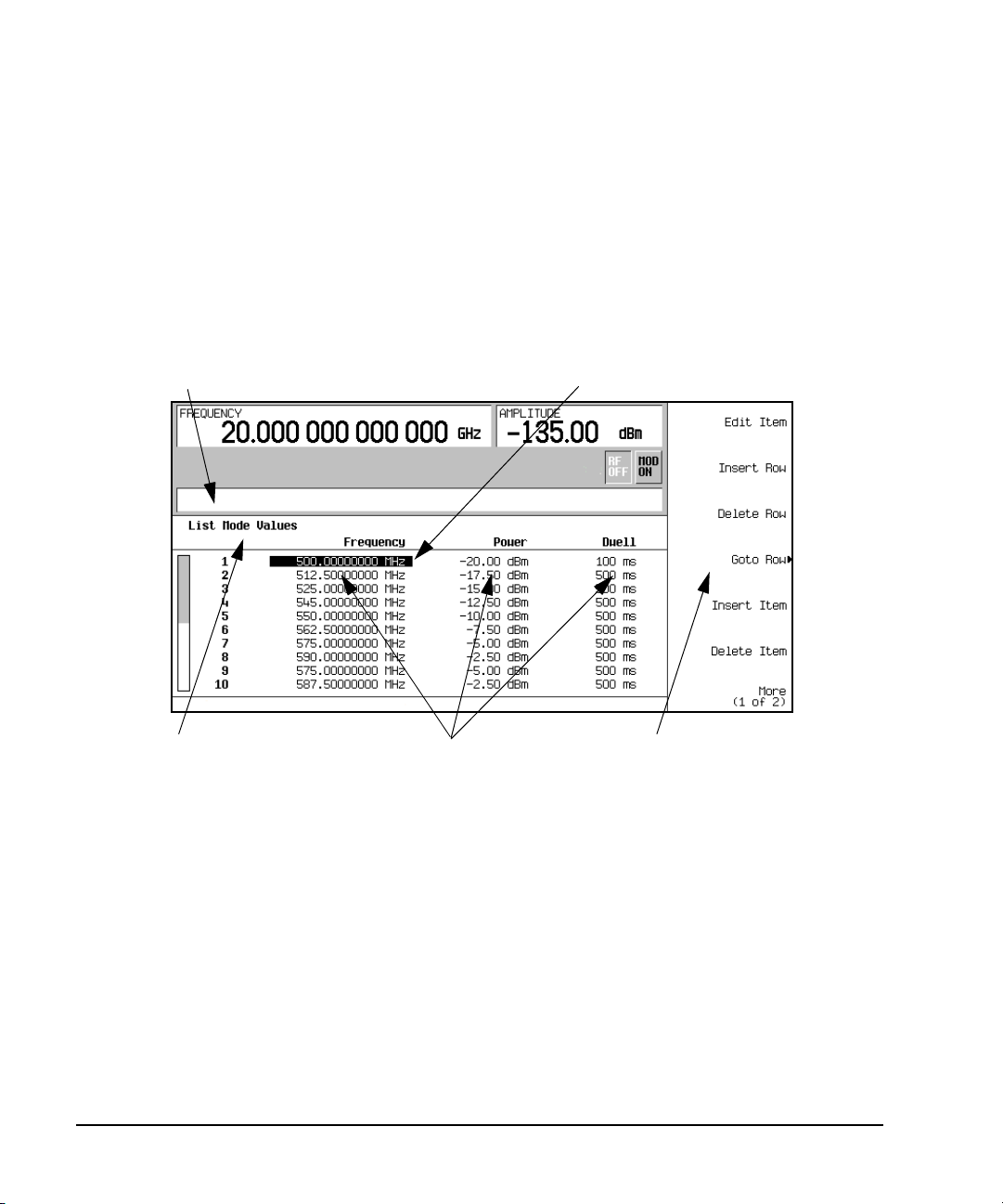
Basic Operation
Cursor
Table Softkeys
Table Name
Tabl e Items
Active Function Area
Using Table Editors
Using Table Editors
Table editors simplify configuration tasks, such as creating a list sweep. This section provides
information to familiarize you with basic table editor functionality using the List Mode Values table
editor as an example.
Preset > Sweep/List > Configure List Sweep.
Press
The signal generator displays the List Mode Values table editor, as shown below.
Figure 2-1
Active Function Area displays the active table item while its value is edited
Cursor an inverse video identifier used to highlight specific table items
for selection and editing
Table Softkeys select table items, preset table values, and modify table
structures
Table Items values arranged in numbered rows and titled columns (The
columns are also known as data fields. For example, the
column below the Frequency title is known as the Frequency
data field).
34 Chapter 2
Page 49

Basic Operation
Using Table Editors
Tab le Ed it or S o f t k e y s
The following table editor softkeys are used to load, navigate, modify, and store table item values.
Edit Item displays the selected item in the active function area of the display where the
item’s value can be modified
Insert Row inserts an identical row of table items above the currently selected row
Delete Row deletes the currently selected row
Goto Row opens a menu of softkeys (Enter, Goto Top Row, Goto Middle Row, Goto Bottom Row, Page Up,
Insert Item inserts an identical item in a new row below the currently selected item
Delete Item deletes the currently selected item
Page Up and
Page Down displays table items that occupy rows outside the limits of the ten- row table
Page Down) used to quickly navigate through the table items
and
display area
More (1 of 2) accesses Load/Store and its associated softkeys
Load/Store opens a menu of softkeys (Load From Selected File, Store To File, Delete File, Goto Row, Page Up,
Page Down) used to load table items from a file in the memory catalog, or to
and
store the current table items as a file in the memory catalog
Modifying Table Items in the Data Fields
1. If not already displayed, open the List Mode Values table editor (Figure 2- 1 on page 34):
2. Use the arrow keys or the knob to move the table cursor over the desired item.
3. Press
4. Use the knob, arrow keys, or the numeric keypad to modify the value.
5. Press
Preset > Sweep/List > Configure List Sweep
Press
In Figure 2- 1, the first item in the Frequency data field is selected.
Edit Item.
The selected item is displayed in the active function area of the display.
Enter.
The modified item is now displayed in the table.
Chapter 2 35
Page 50

Basic Operation
Configuring the RF Output
Configuring the RF Output
This section provides information on how to create continuous wave and swept RF (page 38) outputs.
It also has information on using a mm-Wave source module to extend the signal generator’s
frequency range (page 53).
Configuring a Continuous Wave RF Output
These procedures demonstrate how to set the following parameters:
• RF output frequency
• frequency reference and frequency offset (page 37)
• RF output amplitude (page 37)
• amplitude reference and amplitude offset (page 38)
Setting the RF Output Frequency
Set the RF output frequency to 700 MHz, and increment or decrement the output frequency in 1 MHz
steps.
1. Return the signal generator to the factory- defined state: Press
Preset.
NOTE You can change the preset condition of the signal generator to a user- defined state. For
these examples, however, use the factory- defined preset state (set the
Preset Normal User softkey
in the Utility menu to Normal).
2. Observe the FREQUENCY area of the display (in the upper left- hand corner).
The value displayed is the maximum specified frequency of the signal generator.
3. Press
RF On/Off.
RF On/Off hardkey must be pressed before the RF signal is available at the
The
RF OUTPUT connector. The display annunciator changes from RF OFF to RF ON. The maximum
specified frequency should be output at the RF OUTPUT connector (at the signal generator’s
minimum power level).
4. Press
Frequency > 700 > MHz.
The 700 MHz RF frequency should be displayed in the FREQUENCY area of the display and also in
the active entry area.
5. Press
Frequency > Incr Set > 1 > MHz.
This changes the frequency increment value to 1 MHz.
6. Press the up arrow key.
Each press of the up arrow key increases the frequency by the increment value last set with the
Incr Set hardkey. The increment value is displayed in the active entry area.
7. The down arrow decreases the frequency by the increment value set in the previous step. Practice
stepping the frequency up and down in 1 MHz increments.
You can also adjust the RF output frequency using the knob. As long as frequency is the active
function (the frequency is displayed in the active entry area), the knob will increase and decrease
the RF output frequency.
36 Chapter 2
Page 51

Configuring the RF Output
Basic Operation
8. Use the knob to adjust the frequency back to 700 MHz.
Setting the Frequency Reference and Frequency Offset
The following procedure sets the RF output frequency as a reference frequency to which all other
frequency settings are relative. When the frequency reference is set, the display will read 0.00 Hz
(the frequency output of the signal generator’s hardware minus the reference frequency). Although
the display changes, the actual frequency output is 700 MHz (from step 8 above). Any subsequent
frequency changes are shown as increments or decrements to the 0 Hz reference.
The Frequency Reference Set function is not an active function. Once it is set, any change to the
frequency setting appears as a frequency reading on the signal generator’s front- panel display. For
example,
1. Preset the signal generator: Press
Preset.
2. Set the frequency reference to 700 MHz:
Frequency > 700 > MHz > More (1 of 3) > Freq Ref Set.
Press:
This activates the frequency reference mode, sets the output frequency (700 MHz) as the reference
value, and toggles the
Freq Ref softkey On. The FREQUENCY area displays 0.000 Hz. This reading is
the frequency output of the signal generator’s hardware (700 MHz) minus the reference value
(700 MHz). The signal generator’s true output frequency is 700 MHz. If the
Freq Ref softkey is
toggled to Off, the front-panel will indicate the actual frequency: 700 MHz. The REF indicator
appears on the front- panel display and the
3. Turn on the RF output: Press
RF On/Off.
Freq Ref Off On softkey toggles to On.
The display annunciator changes from RF OFF to RF ON. The RF frequency at the RF OUTPUT
connector is 700 MHz.
4. Set the frequency increment value to 1 MHz: Press
Frequency > Incr Set > 1 > MHz.
5. Increment the output frequency by 1 MHz: Press the up arrow key.
The FREQUENCY area display changes to show 1.000 000 000 MHz, which is the frequency output
by the hardware (700 MHz + 1 MHz) minus the reference frequency (700 MHz). The frequency at
the RF OUTPUT changes to 701 MHz.
6. Enter a 1 MHz offset: Press
More (1 of 3) > Freq Offset > 1 > MHz.
The FREQUENCY area displays 2.000 000 00 MHz, which is the frequency output by the hardware
(701 MHz) minus the reference frequency (700 MHz) plus the offset (1 MHz). The OFFS indicator
activates. The frequency at the RF OUTPUT connector is still 701 MHz.
Setting the RF Output Amplitude
1. Preset the signal generator: Press
Preset.
The AMPLITUDE area of the display shows the minimum power level of the signal generator. This
is the normal preset RF output amplitude.
2. Turn on the RF output: Press
RF On/Off.
The display annunciator changes to RF ON. At the RF OUTPUT connector, the RF signal is output
at the minimum power level.
Chapter 2 37
Page 52

Basic Operation
Configuring the RF Output
3. Change the amplitude to −20 dBm: Press Amplitude > −20 > dBm.
The new output power displays in the AMPLITUDE area of the display and in the active entry area.
Until you press a different front panel function key, amplitude remains the active function. You
can also change the amplitude using the up and down arrow keys or the knob.
Setting the Amplitude Reference and Amplitude Offset
The following procedure sets the RF output power as an amplitude reference to which all other
amplitude parameters are relative. The amplitude initially shown on the display is 0 dB (the power
output by the hardware minus the reference power). Although the display changes, the output power
does not change. Any subsequent power changes are shown as incremental or decremental to 0 dB.
1. Press
2. Set the amplitude to −20 dBm: Press
Preset.
Amplitude > -20 > dBm.
3. Activate the amplitude reference mode and set the current output power (−20 dBm) as the
reference value: Press
More (1 of 2) > Ampl Ref Set.
The AMPLITUDE area displays 0.00 dB, which is the power output by the hardware (−20 dBm)
minus the reference value (−20 dBm). The REF indicator activates and the
Ampl Ref Off On softkey
toggles On.
4. Turn the RF output on: Press
RF On/Off.
The display annunciator changes to RF ON. The power at the RF OUTPUT connector is −20 dBm.
5. Change the amplitude increment value to 10 dB: Press
Incr Set > 10 > dB.
6. Use the up arrow key to increase the output power by 10 dB.
The AMPLITUDE area displays 10.00 dB, which is the power output by the hardware
(- 20 dBm plus 10 dBm) minus the reference power (−20 dBm). The power at the RF OUTPUT
connector changes to −10 dBm.
7. Enter a 10 dB offset: Press
Ampl Offset > 10 > dB.
The AMPLITUDE area displays 20.00 dB, which is the power output by the hardware (−10 dBm)
minus the reference power (−20 dBm) plus the offset (10 dB). The OFFS indicator activates. The
power at the RF OUTPUT connector is still −10 dBm.
Configuring a Swept RF Output
A PSG signal generator has up to three sweep types: step sweep, list sweep, and ramp sweep
(Option 007).
The signal generator indicates the sweep advance in a progress bar on the front- panel display. If the
sweep time is greater than one second, the progress bar sweep advances according to the frequency
span of each segment. For each segment in the span, the progress bar displays the full segment and
then the sweep is taken. With sweep times less than one second, the progress bar is drawn, the
sweep taken, and the progress bar is then blanked.
38 Chapter 2
Page 53

Configuring the RF Output
Basic Operation
NOTE List sweep data cannot be saved within an instrument state, but can be saved to the
memory catalog. For instructions on saving list sweep data, see “Storing Files to the Memory
Catalog” on page 56.
During swept RF output, the FREQUENCY and AMPLITUDE areas of the signal generator’s
display are deactivated, depending on what is being swept.
Step sweep (see page 39) and ramp sweep (see page 41) provide a linear progression through the
start- to- stop frequency and/or amplitude values, while list sweep enables you to create a list of
arbitrary frequency, amplitude, and dwell time values and sweep the RF output based on that list.
The list sweep example uses the points created in the step sweep example as the basis for a new list
sweep.
Ramp sweep (see page 43) is faster than step or list sweep, and is designed to work with an 8757D
Scalar Network Analyzer.
The signal generator provides a softkey, Sweep Retrace Off On, that lets you configure single sweep
behavior. When sweep retrace is on, the signal generator will retrace the sweep to the first point of
the sweep. If the sweep retrace is off, the sweep will stop and remain on the last point in the sweep.
Activating Scalar Pulse in Sweep Configurations
If your sweep setup uses a scalar network analyzer and a DC detector, the PSG must modulate the
swept signal with a 27 kHz square wave, also referred to as a scalar pulse. This pulse modulation is
necessary for the DC detector to properly detect the swept signal. If the PSG is controlled by an
8757D through a GPIB connection, the scalar pulse automatically turns on when DC detection is
selected on the 8757D. When using any other scalar analyzer, you can manually turn on the scalar
pulse using either one of the following key-press sequences:
Sweep/List > Sweep Type > Scalar Pulse Off On to On
Press
or
Pulse > Pulse Source > Scalar > Pulse Off On to On
Press
Using Step Sweep
Step sweep provides a linear progression through the start- to- stop frequency and/or amplitude
values. You can toggle the direction of the sweep, up or down. When the
Sweep Direction Down Up softkey
is set to Up, values are swept from the start amplitude/frequency to the stop amplitude/frequency.
When set to Down, values are swept from the stop amplitude/frequency to the start
amplitude/frequency.
When a step sweep is activated, the signal generator sweeps the RF output based on the values
entered for RF output start and stop frequencies and amplitudes, a number of equally spaced points
(steps) to dwell upon, and the amount of dwell time at each point; dwell time is the minimum period
of time after the settling time that the signal generator will remain at its current state. The
frequency, amplitude, or frequency and amplitude of the RF output will sweep from the start
amplitude/frequency to the stop amplitude/frequency, dwelling at equally spaced intervals defined by
# Points softkey value.
the
Chapter 2 39
Page 54

Basic Operation
Configuring the RF Output
To Configure a Single Step Sweep
In this procedure, you create a step sweep with nine, equally- spaced points, and the following
parameters:
• frequency range from 500 MHz to 600 MHz
•amplitude from −20 dBm to 0 dBm
• dwell time 500 ms at each point
1. Press
2. Press
Preset.
Sweep/List.
This opens a menu of sweep softkeys.
3. Press
Sweep Repeat Single Cont.
This toggles the sweep repeat from continuous to single.
4. Press
Configure Step Sweep.
5. Press Freq Start > 500 > MHz.
This changes the start frequency of the step sweep to 500 MHz.
6. Press
Freq Stop > 600 > MHz.
This changes the stop frequency of the step sweep to 600 MHz.
7. Press
Ampl Start > -20 > dBm.
This changes the amplitude level for the start of the step sweep.
8. Press
Ampl Stop > 0 > dBm.
This changes the amplitude level for the end of the step sweep.
9. Press
# Points > 9 > Enter.
This sets the number of sweep points to nine.
10. Press
Step Dwell > 500 > msec.
This sets the dwell time at each point to 500 milliseconds.
11. Press
Return > Sweep > Freq & Ampl.
This sets the step sweep to sweep both frequency and amplitude data. Selecting this softkey
returns you to the previous menu and turns on the sweep function.
12. Press
RF On/Off.
The display annunciator changes from RF OFF to RF ON.
13. Press
Single Sweep.
A single sweep of the frequencies and amplitudes configured in the step sweep is executed and
available at the RF OUTPUT connector. On the display, the SWEEP annunciator appears for the
duration of the sweep and a progress bar shows the progression of the sweep. The
Single Sweep
softkey can also be used to abort a sweep in progress. To see the frequencies sweep again, press
Single Sweep to trigger the sweep.
40 Chapter 2
Page 55

Configuring the RF Output
Basic Operation
To Configure a Continuous Step Sweep
Sweep Repeat Single Cont.
Press
This toggles the sweep from single to continuous. A continuous repetition of the frequencies and
amplitudes configured in the step sweep are now available at the RF OUTPUT connector. The SWEEP
annunciator appears on the display, indicating that the signal generator is sweeping and progression
of the sweep is shown by a progress bar.
Using List Sweep
List sweep enables you to create a list of arbitrary frequency, amplitude, and dwell time values and
sweep the RF output based on the entries in the List Mode Values table.
Unlike a step sweep that contains linear ascending/descending frequency and amplitude values,
spaced at equal intervals throughout the sweep, list sweep frequencies and amplitudes can be entered
at unequal intervals, nonlinear ascending/descending, or random order.
For convenience, the List Mode Values table can be copied from a previously configured step sweep.
Each step sweep point’s associated frequency, amplitude and dwell time values are entered into a
row in the List Mode Values table, as the following example illustrates.
To Configure a Single List Sweep Using Step Sweep Data
In this procedure, you will leverage the step sweep points and change the sweep information by
editing several points in the List Mode Values table. For information on using tables, see “Using Table
Editors” on page 34.
1. Press
Sweep Repeat Single Cont.
This toggles the sweep repeat from continuous to single. The SWEEP annunciator is turned off. The
sweep will not occur until it is triggered.
2. Press
Sweep Type List Step.
This toggles the sweep type from step to list.
3. Press
Configure List Sweep.
This opens another menu displaying softkeys that you will use to create the sweep points. The
display shows the current list data. (When no list has been previously created, the default list
contains one point set to the signal generator’s maximum frequency, minimum amplitude, and a
dwell time of 2 ms.)
4. Press
More (1 of 2) > Load List From Step Sweep > Confirm Load From Step Data.
The points you defined in the step sweep are automatically loaded into the list.
To Edit List Sweep Points
1. Press
Return > Sweep > Off.
Turning the sweep off allows you to edit the list sweep points without generating errors. If sweep
remains on during editing, errors occur whenever one or two point parameters (frequency, power,
and dwell) are undefined.
2. Press
Configure List Sweep.
This returns you to the sweep list table.
Chapter 2 41
Page 56

Basic Operation
Configuring the RF Output
3. Use the arrow keys to highlight the dwell time in row 1.
4. Press
Edit Item.
The dwell time for point 1 becomes the active function.
5. Press
100 > msec.
This enters 100 ms as the new dwell time value for row 1. Note that the next item in the table
(in this case, the frequency value for point 2) becomes highlighted after you press the terminator
softkey.
6. Using the arrow keys, highlight the frequency value in row 4.
7. Press
Edit Item > 545 > MHz.
This changes the frequency value in row 4 to 545 MHz.
8. Highlight any column in the point 7 row and press
Insert Row.
This adds a new point between points 7 and 8. A copy of the point 7 row is placed between
points 7 and 8, creating a new point 8, and renumbering the successive points.
9. Highlight the frequency item for point 8, then press
Pressing
Insert Item shifts frequency values down one row, beginning at point 8. Note that the
Insert Item.
original frequency values for both points 8 and 9 shift down one row, creating an entry for point
10 that contains only a frequency value (the power and dwell time items do not shift down).
The frequency for point 8 is still active.
10. Press
11. Press
590 > MHz.
Insert Item > -2.5 > dBm.
This inserts a new power value at point 8 and shifts down the original power values for points 8
and 9 by one row.
12. Highlight the dwell time for point 9, then press
Insert Item.
A duplicate of the highlighted dwell time is inserted for point 9, shifting the existing value down
to complete the entry for point 10.
To Configure a Single List Sweep
1. Press Return > Sweep > Freq & Ampl
This turns the sweep on again. No errors should occur if all parameters for every point have been
defined in the previous editing process.
2. Press
Single Sweep.
The signal generator will single sweep the points in your list. The SWEEP annunciator activates
during the sweep.
3. Press
4. Press
More (1 of 2) > Sweep Trigger > Tri gg er K ey .
This sets the sweep trigger to occur when you press the
More (2 of 2) > Single Sweep.
Tr ig g er hardkey.
This arms the sweep. The ARMED annunciator is activated.
42 Chapter 2
Page 57

Configuring the RF Output
Basic Operation
5. Press the Trigger hardkey.
The signal generator will single sweep the points in your list and the SWEEP annunciator will be
activated during the sweep.
To Configure a Continuous List Sweep
Sweep Repeat Single Cont.
Press
This toggles the sweep from single to continuous. A continuous repetition of the frequencies and
amplitudes configured in the list sweep are now available at the RF OUTPUT connector. The SWEEP
annunciator appears on the display, indicating that the signal generator is sweeping and progression
of the sweep is shown by a progress bar.
Using Ramp Sweep (Option 007)
Ramp sweep provides a linear progression through the start- to- stop frequency and/or amplitude
values. Ramp sweep is much faster than step or list sweep, and is designed to work with an
8757D Scalar Network Analyzer. This section describes the ramp sweep capabilities available in PSG
signal generators with Option 007. You will learn how to use basic ramp sweep, and how to configure
a ramp sweep for a master/slave setup (see page 50).
Refer to the E8257D/67D PSG Signal Generators Programming Guide for an example program that
uses pass-thru commands in a ramp sweep system (pass-thru commands enable you to temporarily
interrupt ramp sweep system interaction so that you can send operating instructions to the PSG).
Using Basic Ramp Sweep Functions
This procedure demonstrates the following tasks (each task builds on the previous task):
• “Configuring a Frequency Sweep” on page 43
• “Using Markers” on page 46
• “Adjusting Sweep Time” on page 48
• “Using Alternate Sweep” on page 49
• “Configuring an Amplitude Sweep” on page 50
Configuring a Frequency Sweep
1. Set up the equipment as shown in Figure 2- 2.
NOTE The PSG signal generator is not compatible with the GPIB system interface of an 8757A,
8757C, or 8757E. For these older scalar network analyzers, do not connect the GPIB cable in
Figure 2-2. This method provides only a subset of 8757D functionality. See the PSG Data
Sheet for details. Use the 8757A/C/E documentation instead of this procedure.
Chapter 2 43
Page 58

Basic Operation
Configuring the RF Output
Figure 2-2 Equipment Setup
2. Turn on both the 8757D and the PSG.
3. On the 8757D, press
System > More > Sweep Mode and verify that the SYSINTF softkey is set to ON.
This ensures that the system interface mode is activated on the 8757D. The system interface
mode enables the instruments to work as a system.
4. Press
5. On the 8757D, press
Utility > GPIB/RS-232 LAN to view the PSG’s GPIB address under the GPIB Address softkey. If you
want to change it, press
GPIB Address and change the value.
LOCAL > SWEEPER and check the GPIB address. If it does not match that of the
PSG, change the value.
6. Preset either instrument.
Presetting one of the instruments should automatically preset the other as well. If both
instruments do not preset, check the GPIB connection, GPIB addresses, and ensure the 8757D is
set to system interface mode (
SYSINTF set to ON).
The PSG automatically activates a 2 GHz to maximum frequency ramp sweep with a constant
amplitude of 0 dBm. Notice that the RF ON, SWEEP, and PULSE annunciators appear on the PSG
display. The PULSE annunciator appears because the 8757D is operating in AC mode.
The PSG also switches its remote language setting to 8757D System, allowing the PSG to talk to
the 8757D during ramp sweep operations. You can confirm this by pressing
and observing the selection under the
44 Chapter 2
Remote Language softkey.
Utility > GPIB/RS-232 LAN
Page 59

Configuring the RF Output
Basic Operation
NOTE During swept RF output, the FREQUENCY and/or AMPLITUDE areas of the signal generator’s
display are deactivated, depending on what is being swept. In this case, since frequency
is being swept, nothing appears in the FREQUENCY area of the display.
7. Press Frequency > Freq CW.
The current continuous wave frequency setting now controls the RF output and ramp sweep is
turned off.
8. Press
Freq Start.
The ramp sweep settings once again control the RF output and the CW mode is turned off.
Pressing any one of the softkeys
Freq Start, Freq Stop, Freq Center, or Freq Span activates a ramp sweep
with the current settings.
NOTE In a frequency ramp sweep, the start frequency must be lower than the stop frequency.
9. Adjust the settings for Freq Center and Freq Span so that the frequency response of the device under
test (DUT) is clearly seen on the 8757D display.
Notice how adjusting these settings also changes the settings for the
Freq Start and Freq Stop softkeys.
You may need to rescale the response on the 8757D for a more accurate evaluation of the
amplitude. Figure 2- 3 on page 46 shows an example of a bandpass filter response.
Chapter 2 45
Page 60
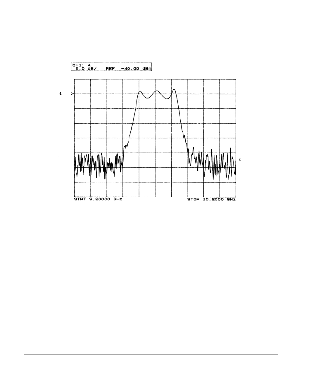
Basic Operation
Configuring the RF Output
Figure 2-3 Bandpass Filter Response on 8757D
Using Markers
1. Press
Markers.
This opens a table editor and associated marker control softkeys. You can use up to 10 different
markers, labeled 0 through 9.
2. Press
Marker Freq and select a frequency value within the range of your sweep.
In the table editor, notice how the state for marker 0 automatically turns on. The marker also
appears on the 8757D display.
3. Use the arrow keys to move the cursor in the table editor to marker 1 and select a frequency
value within the range of your sweep, but different from marker 0.
Notice that marker 1 is activated and is the currently selected marker, indicated by the marker
arrow pointing down. As you switch between markers, using the arrow keys, you will notice that
the selected marker’s arrow points down, while all others point up.
Notice also that the frequency and amplitude data for the currently selected marker is displayed
on the 8757D.
46 Chapter 2
Page 61
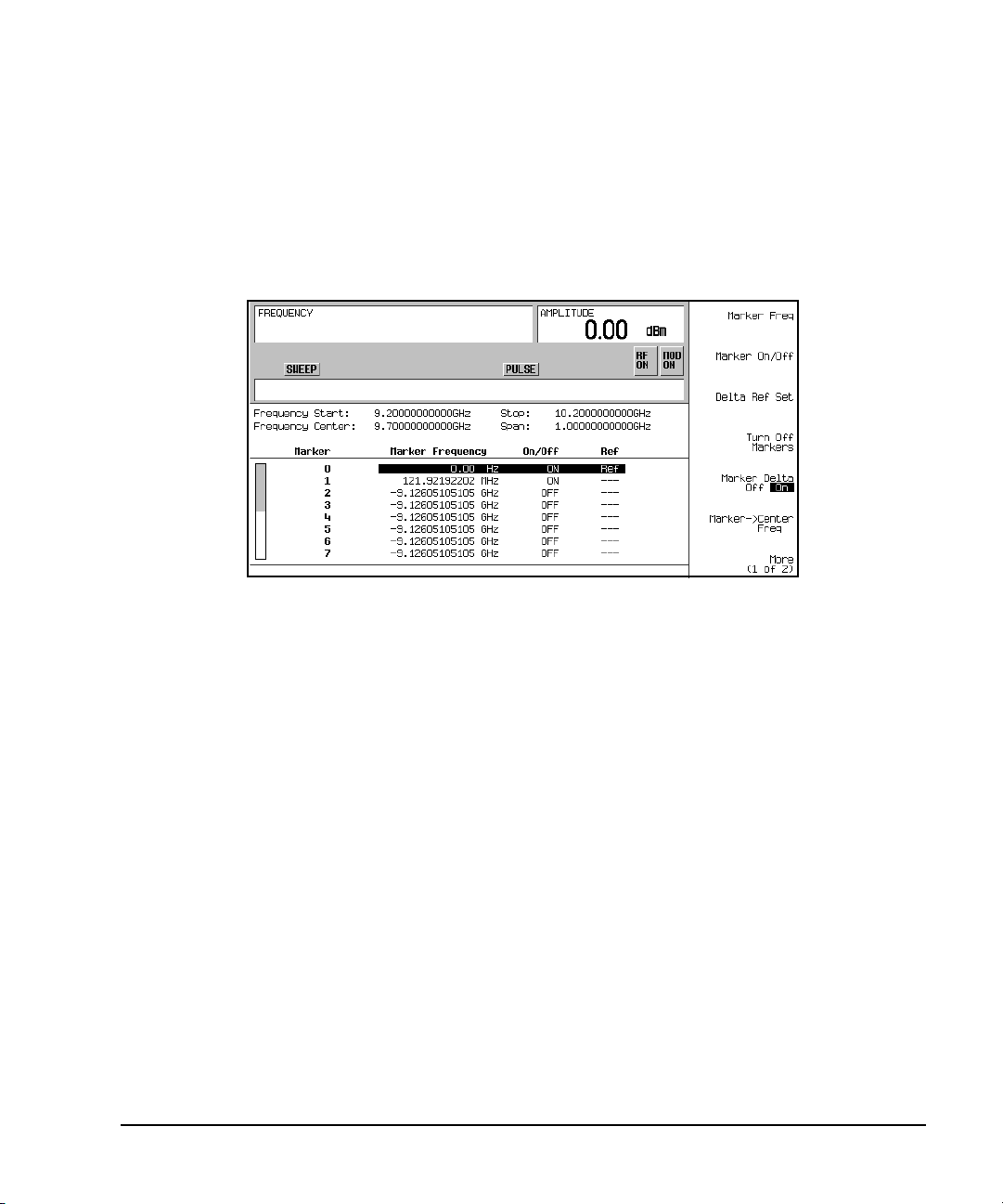
Configuring the RF Output
Basic Operation
4. Move the cursor back to marker 0 and press Delta Ref Set > Marker Delta Off On to On.
In the table editor, notice that the frequency values for each marker are now relative to marker 0.
Ref appears in the far right column (also labeled Ref) to indicate which marker is the reference.
Refer to Figure 2- 4.
Figure 2-4 Marker Table Editor
5. Move the cursor back to marker 1 and press
Marker Freq. Turn the front panel knob while
observing marker 1 on the 8757D.
On the 8757D, notice that the displayed amplitude and frequency values for marker 1 are relative
to marker 0 as the marker moves along the trace. Refer to Figure 2- 5.
Chapter 2 47
Page 62

Basic Operation
Configuring the RF Output
Figure 2-5 Delta Markers on 8757D
6. Press
Turn Off Markers.
All active markers turn off. Refer to the E8257D/67D PSG Signal Generators Key Reference for
information on other marker softkey functions.
Adjusting Sweep Time
1. Press
Sweep/List.
This opens a menu of sweep control softkeys and displays a status screen summarizing all the
current sweep settings.
2. Press
Configure Ramp/Step Sweep.
Since ramp is the current sweep type, softkeys in this menu specifically control ramp sweep
settings. When step is the selected sweep type, the softkeys control step sweep settings. Notice
that the
Freq Start and Freq Stop softkeys appear in this menu in addition to the Frequency hardkey
menu.
3. Press
Sweep Time to Manual > 5 > sec.
In auto mode, the sweep time automatically sets to the fastest allowable value. In manual mode,
you can select any sweep time slower than the fastest allowable. The fastest allowable sweep time
is dependent on the number of trace points and channels being used on the 8757D and the
frequency span.
48 Chapter 2
Page 63

4. Press Sweep Time to Auto.
The sweep time returns to its fastest allowable setting.
Configuring the RF Output
Basic Operation
NOTE When using an 8757 network analyzer in manual sweep mode, you must activate the signal
generator’s
Sweep/List > More (2 of 3) > Manual Freq
Manual Freq softkey before using the front panel knob to control the sweep. Press
Using Alternate Sweep
1. Press the Save hardkey.
This opens the table editor and softkey menu for saving instrument states. Notice that the
softkey is active. (For more information on saving instrument states refer to “Using the
Reg
Select
Instrument State Registers” on page 57.)
2. Turn the front panel knob until you find an available register and press
SAVE. Remember this
saved register number. If no registers are available, you can write over an in- use register, by
pressing
Re-SAVE.
NOTE When you are using the PSG in a system with an 8757 network analyzer, you are limited to
using registers 1 through 9 in sequence 0 for saving and recalling states.
3. Press Sweep/List > Configure Ramp/Step Sweep and enter new start and stop frequency values for the
ramp sweep.
4. Press
Alternate Sweep Register and turn the front panel knob to select the register number of the
previously saved sweep state.
5. Press
Alternate Sweep Off On to On.
The signal generator alternates between the original saved sweep and the current sweep. You may
need to adjust 8757D settings to effectively view both sweeps, such as setting channel 2 to
measure sensor A. Refer to Figure 2- 6.
Chapter 2 49
Page 64

Basic Operation
Configuring the RF Output
Figure 2-6 Alternating Sweeps on 8757D
Configuring an Amplitude Sweep
1. Press Return > Sweep > Off.
This turns off both the current sweep and the alternate sweep from the previous task. The
current CW settings now control the RF output.
2. Press
3. Using the
4. Press
Configure Ramp/Step Sweep.
Ampl Start and Ampl Stop softkeys, set an amplitude range to be swept.
Return > Sweep > Ampl.
The new amplitude ramp sweep settings control the RF output and the CW mode is turned off.
Configuring a Ramp Sweep for a Master/Slave Setup
This procedure shows you how to configure two PSGs and an 8757D to work in a master/slave setup.
The master/slave control setup must use two instruments from the same signal generator family such
as two PSG’s, or two 83640B’s, or two 83751B’s.
NOTE The master/slave setup applies to ramp sweep only, not step sweep or list sweep. To use this
setup, you must have two sources from the same signal generator family such as two PSG’s,
or two 83640B’s, or two 83751B’s.
50 Chapter 2
Page 65

Configuring the RF Output
Basic Operation
1. Set up the equipment as shown in Figure 2- 7. Use a 9- pin, D- subminiature, male RS- 232 cable
with the pin configuration shown in Figure 2- 8 on page 52 to connect the auxiliary interfaces of
the two PSGs. You can also order the cable (part number 8120- 8806) from Agilent Technologies.
By connecting the master PSG’s 10 MHz reference standard to the slave PSG’s 10 MHz reference
input, the master’s timebase supplies the frequency reference for both PSGs.
2. Set up the slave PSG’s frequency and power settings.
By setting up the slave first, you avoid synchronization problems.
3. Set up the master PSG’s frequency, power, and sweep time settings.
The two PSGs can have different frequency and power settings for ramp sweep.
4. Set the slave PSG’s sweep time to match that of the master.
Sweep times must be the same for both PSGs.
5. Set the slave PSG to continuous triggering.
The slave must be set to continuous triggering, but the master can be set to any triggering mode.
6. On the slave PSG, press
Sweep/List > Sweep Type > Ramp Sweep Control > Slave.
This sets the PSG to operate in slave mode.
7. On the master PSG, press
Sweep/List > Sweep Type > Ramp Sweep Control > Master. This sets the PSG to
operate in master mode.
Chapter 2 51
Page 66

Basic Operation
Configuring the RF Output
Figure 2-7 Master/Slave Equipment Setup
Figure 2-8 RS-232 Pin Configuration
52 Chapter 2
Page 67

Basic Operation
Modulating a Signal
Extending the Frequency Range
You can extend the signal generator frequency range using an Agilent 83550 series millimeter- wave
source module or other manufacturer’s mm- source module. Refer to “Millimeter-Wave Source
Modules” on page 236 for information on using the signal generator with a millimeter- wave source
module.
Modulating a Signal
This section describes how to turn on a modulation format, and how to apply it to the RF output.
Turning On a Modulation Format
A modulation format can be turned on prior to or after setting the signal parameters.
1. Access the first menu within the modulation format.
This menu displays a softkey that associates the format’s name with off and on. For example,
> AM Off On
one.
2. Press the modulation format off/on key until On highlights.
Figure 2-9 shows the portion of the AM modulation format’s first menu that displays the state of
the modulation format, as well as the active modulation format annunciator.
The modulation format generates, but the carrier signal is not modulated until you apply it to the
RF output (see page 54).
Depending on the modulation format, the signal generator may require a few seconds to build the
signal. Within the digital formats (E8267D PSG with Option 601/602 only), you may see a BaseBand
Reconfiguring status bar appear on the display. Once the signal is generated, an annunciator
showing the name of the format appears on the display, indicating that the modulation format is
active. For digital formats (E8267D PSG with Option 601/602 only), the I/Q annunciator appears in
addition to the name of the modulation format.
. For some formats, the off/on key may appear in additional menus other than the first
AM
Chapter 2 53
Page 68

Basic Operation
First AM Menu
Modulation format is off
Modulation format is on
Active Modulation Format Annunciator
Modulating a Signal
Figure 2-9 Example of AM Modulation Format Off and On
Applying a Modulation Format to the RF Output
The carrier signal is modulated when the Mod On/Off key is set to On, and an individual modulation
format is active.
When the
is set to On, the MOD ON annunciator shows in the display, whether or not there is an active
modulation format. The annunciators simply indicate whether the carrier signal will be modulated
when a modulation format is turned on.
Mod On/Off key is set to Off, the MOD OFF annunciator appears on the display.When the key
To Turn RF Output Modulation On
Press the
Mod On/Off key until the MOD ON annunciator appears in the display.
The carrier signal should be modulated with all active modulation formats. This is the factory default.
To Turn RF Output Modulation Off
Press the
Mod On/Off key until the MOD OFF annunciator appears in the display.
The carrier signal is no longer modulated or capable of being modulated when a modulation format
is active.
54 Chapter 2
Page 69

Figure 2-10 Carrier Signal Modulation Status
Mod Set to On—Carrier is Modulated
AM Modulation Format is Active
AM Modulation Format is Active
Mod Set to Off—Carrier is
not Modulated
Mod Set to On—Carrier is
not Modulated
No Active Modulation Format
Using Data Storage Functions
Basic Operation
Using Data Storage Functions
This section explains how to use the two forms of signal generator data storage: the memory catalog
and the instrument state register.
Using the Memory Catalog
The Memory Catalog is the signal generator’s interface for viewing, storing, and saving files; it can be
accessed through the signal generator’s front panel or a remote controller. (For information on
performing these tasks remotely, see the E8257D/67D PSG Signal Generators Programming Guide.)
Chapter 2 55
Page 70

Basic Operation
Using Data Storage Functions
Table 2-1 Memory Catalog File Types and Associated Data
Binary binary data
State instrument state data (controlling instrument operating parameters,
LIST sweep data from the List Mode Values table including frequency,
User Flatness user flatness calibration correction pair data (user-defined
FIR Finite Impulse Response (FIR) filter coefficients
ARB Catalog Types (E8267D PSG with Option 601/602 only) user created files -
Modulation Catalog T ypes (E8267D PSG with Option 601/602 only) associated data for I/Q and
Shape burst shape of a pulse
Bit Bit
such as frequency, amplitude, and mode)
amplitude, and dwell time
frequency and corresponding amplitude correction values)
Waveform Catalog Types: WFM1 (waveform file),
NVARB Catalog Types:
NVWFM (non-volatile, ARB waveform file),
NVMKR (non- volatile, ARB waveform marker file),
Seq (ARB sequence file),
MTONE (ARB multitone file),
DMOD (ARB digital modulation file), MDMOD (ARB multicarrier
digital modulation file)
FSK (frequency shift keying) modulation files
Storing Files to the Memory Catalog
To store a file to the memory catalog, first create a file. For this example, use the default list sweep
table.
1. Press
2. Press
Preset.
Sweep/List > Configure List Sweep > More (1 of 2) > Load/Store.
This opens the “Catalog of List Files”.
3. Press
Store to File.
This displays a menu of alphabetical softkeys for naming the file. Store to: is displayed in the
active function area.
4. Enter the file name LIST1 using the alphabetical softkeys and the numeric keypad (for the
numbers 0 to 9).
5. Press
Enter.
The file should be displayed in the “Catalog of List Files”, showing the file name, file type, file
size, and the date and time the file was modified.
56 Chapter 2
Page 71

Using Data Storage Functions
Basic Operation
Viewing Stored Files in the Memory Catalog
1. Press
Utility > Memory Catalog > Catalog Type.
All files in the memory catalog are listed in alphabetical order, regardless of which catalog type
you select. File information appears on the display and includes the file name, file type, file size,
and the date and time the file was modified.
2. Press
List.
The “Catalog of List Files” is displayed.
3. Press
Catalog Type > State.
The “Catalog of State Files” is displayed.
4. Press
Catalog Type > All.
The “Catalog of All Files” is displayed. For a complete list of file types, refer to Table 2- 1 on
page 56.
Using the Instrument State Registers
The instrument state register is a section of memory divided into 10 sequences (numbered 0 through
9) with each sequence consisting of 100 registers (numbered 00 through 99). Instrument state
sequences and registers are used to store and recall instrument settings and provide a quick way to
reconfigure the signal generator when switching between different instrument and signal
configurations. The signal generator with Option 005 (internal hard drive) has approximately 4 GB
available for storing instrument state files and other user data. Without Option 005, the signal
generator has 20 MB available for data and instrument state storage. Instrument state files can vary
in length depending on the signal generator’s configuration.
File data, such as modulation formats, arb setups, and table entries, are not stored with the save
function. Only setups such as frequency, attenuation, power and other user-defined settings that do
not survive a power cycle or instrument reset can be saved to a sequence and register. Any data file,
such as an arb format file, associated with the instrument state will only be referenced by its file
name. Once an instrument state has been saved, recalling that state will setup the generator with the
saved settings and load the associated file data.
For more information on storing file data such as modulation formats, arb setups, and table entries
refer to “Storing Files to the Memory Catalog” on page 56. Refer to the E8257D/67D PSG Signal
Generators Programming Guide and the E7257D/67D PSG Signal Generators Key Reference for more
information on the save and recall function.
NOTE A reference to a file is saved along with the instrument state. However, no data is saved
with the save function. You must store file data, using store commands, in a different
memory location.
Saving an Instrument State
1. Preset the signal generator, then turn on amplitude modulation (the AM annunciator will turn on):
a. Press
b. Press
Frequency > 800 > MHz.
Amplitude > 0 > dBm.
c. Press AM > AM Off On.
Chapter 2 57
Page 72

Basic Operation
Using Data Storage Functions
2. Press Save > Select Seq.
The sequence number becomes the active function. The signal generator displays the last sequence
used. Using the arrow keys, set the sequence to 1.
3. Press
Select Reg.
The register number in sequence 1 becomes the active function. The signal generator displays
either the last register used accompanied by the text: (in use), or (if no registers are in use)
register 00 accompanied by the text: (available). Use the arrow keys to select register 01.
4. Press
Save Seq[1] Reg[01].
This saves this instrument state in sequence 1, register 01 of the instrument state register.
5. Press
Add Comment to Seq[1] Reg[01].
This enables you to add a descriptive comment to sequence 1 register 01.
6. Using the alphanumeric softkeys or the knob, enter a comment and press
7. Press
Edit Comment In Seq[1] Reg[01].
Enter.
If you wish, you can now change the descriptive comment for sequence 1 register 01.
After making changes to an instrument state, you can save it back to a specific register by
highlighting that register and pressing Re-SAVE Seq[n] Reg[nn].
Recalling an Instrument State
Using this procedure, you will learn how to recall instrument settings saved to an instrument state
register.
1. Press
2. Press the
3. Press
Preset.
Recall hardkey.
Notice that the
RECALL Reg.
Select Seq softkey shows sequence 1. (This is the last sequence that you used.)
The register to be recalled in sequence 1 becomes the active function. Press the up arrow key
once to select register 1. Your stored instrument state settings should have been recalled.
Deleting Registers and Sequences
These procedures describe how to delete registers and sequences saved to an instrument state
register.
Deleting a Specific Register within a Sequence
1. Press
2. Press the
3. Press
58 Chapter 2
Preset.
Recall or Save hardkey.
Notice that the
Select Seq and enter the sequence number containing the register you want to delete.
Select Seq softkey shows the last sequence that you used.
Page 73

4. Press Select Reg and enter the register number you want to delete.
Notice that the
Delete Seq[n] Reg[nn] should be loaded with the sequence and register you want to
delete.
5. Press
Delete Seq[n] Reg[nn].
This deletes the chosen register.
Deleting All Registers within a Sequence
1. Press Preset.
2. Press the
Notice that the
3. Press
4. Press
Recall or Save hardkey.
Select Seq softkey shows the last sequence that you used.
Select Seq and enter the sequence number containing the registers you want to delete.
Delete all Regs in Seq[n].
This deletes all registers in the selected sequence.
Deleting All Sequences
Basic Operation
Using Security Functions
CAUTION Be sure you want to delete the contents of all registers and all sequences in the
instrument state register.
1. Press Preset.
2. Press the
Notice that the
3. Press
Recall or Save hardkey.
Select Seq softkey shows the last sequence that you used.
Delete All Sequences.
This deletes all of the sequences saved in the instrument state register.
8757 Network Analyzer Save and Recall Functions
The 8757 network analyzer family can save and recall signal generator instrument states although
communication between the instruments is limited.
A clear register command from the 8757 will cause the signal generator to replace a register’s
contents with default values. Default values can be cleared from the signal generator by using the
Delete All softkey menu or by using the corresponding SCPI (Standard Commands for Programmable
Instruments) command.
The signal generator does not communicate directly with the 8757 network analyzer. If the 8757 saves
an instrument state to a signal generator register and the user deletes that register, the 8757 will not
recognize the deletion. An attempt, by the 8757, to recall a deleted state will cause the PSG to
generate the error message: +700 “State Save Recall Error...”.
Using Security Functions
This section describes how to use the PSG’s security functions to protect and remove classified
proprietary information stored or displayed in the instrument. All security functions described in this
Chapter 2 59
Page 74

Basic Operation
Using Security Functions
section also have an equivalent SCPI command for remote operation. (Refer to the “System
Commands” chapter of the E8257D/67D PSG Signal Generators SCPI Command Reference for more
information.)
Understanding PSG Memory Types
The PSG comprises several memory types, each used for storing a specific type of data. Before
removing sensitive data, it is important to understand how each memory type is used in the PSG.
The following tables describe each memory type used in the base instrument, optional baseband
generator, and optional hard disk.
Table 2-2 Base Instrument Memory
Memory
Type
and Size
Main
Memory
(SDRAM)
64 MB
Main
Memory
(Flash)
20 MB
Firmware
Memory
(Flash)
12 MB
Purpose/Contents Data Input Method Location in Instrument and Remarks
Writa ble D ur in g
Normal Operation ?
Data Retained
When Powered Off?
Yes No firmware operating
Yes Yes fa ct or y
No Yes main firmware image factory installed or
Yes Yes LAN configuration front panel entry or
memory
calibration/configuratio
n data
user file system, which
includes instrument
status backup, flatness
calibration, IQ
calibration, instrument
states, waveforms
(including header and
marker data),
modulation definitions,
and sweep lists
operating system
(not user)
firmware upgrades
and user-saved data
firmware upgrade
remotely
CPU board, not battery backed.
CPU board (same chip as firmware memory, but
managed separately)
User data is not stored in this memory if hard disk
(Option 005) is installed.
Because this 32-MB memory chip contains 20 MB of
user data (described here) and 12 MB of firmware
memory, a selective chip erase is performed. User
data areas are selectively and completely sanitized
when you perform the
CPU board (same chip as main flash memory, but
managed separately)
During normal operation, this memory cannot be
overwritten except for LAN configuration. It is only
overwritten during the firmware installation or
upgrade process.
Because this 32-MB memory chip contains 20 MB of
user data and 12 MB of firmware memory (described
here), a selective chip erase is performed. User data
areas are selectively and completely sanitized when
you perform the
Erase and Sanitize function.
Erase and Sanitize function.
60 Chapter 2
Page 75

Table 2-2 Base Instrument Memory (Continued)
Basic Operation
Using Security Functions
Memory
Type
and Size
Battery
Backed
Memory
(SRAM)
512 kB
Bootrom
Memory
(Flash)
128 kB
Calibration
Backup
Memory
(Flash)
512 KB
Boards
Memory
(Flash)
512 Bytes
Micro-
processor
Cache
(SRAM)
3 kB
Purpose/Contents Data Input Method Location in Instrument and Remarks
Writa ble D ur in g
Normal Ope ratio n?
Data Retained
When Powered Off?
Yes Yes user- editable data
No Yes CPU bootup program
No Yes fact or y
No Yes factory calibration and
Yes No CPU data and
(table editors)
last instrument state,
last instrument state
backup, and persistent
instrument state and
instrument status
and firmware
loader/updater
calibration/configuratio
n data backup
no user data
information files, code
images, and self- test
limits
no user data
instruction cache
firmware operations CPU board
The battery can be removed to sanitize the memory,
but must be reinstalled for the instrument to operate.
The battery is located on the CPU board.
factory programmed CPU board
During normal operation, this memory cannot be
overwritten or erased. This read-only data is
programmed at the factory.
factory or service
only
factory or service
only
memory is managed
by CPU, not user
motherboard
all RF boards, baseband generator, and motherboard
CPU board, not battery backed.
Table 2-3 Baseband Generator Memory (Options 601 and 602)
Memory
Type
and Size
Wave form
Memory
(SDRAM)
40−320 MB
Writable Dur ing
Normal Operation?
Yes No waveforms (including header
Purpose/Contents Data Input Method Remarks
Data Retained
When Powered Off?
and marker data) and PRAM
normal user
operation
User data is completely sanitized when you
perform the
backed.
Erase and Sa nitize function. Not battery
Chapter 2 61
Page 76

Basic Operation
Using Security Functions
Table 2-3 Baseband Generator Memory (Options 601 and 602) (Continued)
Memory
Type
and Size
BBG
Firmware
Memory
(Flash)
32 MB
Coprocessor
Memory
(SRAM)
32 MB
Buffer
Memory
(SRAM)
5 x 512 kB
Writ able Dur ing
Norma l Ope ration?
No Yes firmware image for
Yes N o op era t ing m e mor y o f
No No support buffer memor y for
Purpose/Contents Data Input Method Remarks
Data Retained
When Powered Off?
baseband generator
baseband coprocessor CPU
ARB and real- time
applications
firmware upgrade
During normal
operation, some
user information,
such as payload
data, can remain in
the memory.
normal user
operation
Table 2-4 Hard Disk Memory
This memory is used during normal baseband
generator operation. It is not directly accessible by
the user. Not battery backed.
This memory is used during normal baseband
generator operation. It is not directly accessible by
the user. Not battery backed.
Memory
Type
and Size
Media
Storage
(Built- in
Hard Disk)
6GB or
10 GB
(4 GB usable
in both
cases)
Buffer
Memory
(DRAM)
512 kB
Writa ble During
Normal Operation ?
Yes Yes user files, including f latness
No No buffer (cache) memory normal operation
Purpose/Contents Data Input Method Remarks
Data Retained
When Powered Off?
calibrations, IQ calibration,
instrument states,
waveforms (including header
and marker data),
modulation definitions, and
sweep lists
user-saved data The magnetic residue requires several rewrite
through hard disk
cycles or drive removal and destruction.
The hard disk is an option and is therefore
not installed in some instruments. If it is
installed, these files are stored on the hard
disk instead of in flash memor y.
User data is completely sanitized when you
perform the
Erase and Sanitize function.
62 Chapter 2
Page 77

Basic Operation
Using Security Functions
Removing Sensitive Data from PSG Memory
When moving the PSG from a secure development environment, you can remove any classified
proprietary information stored in the instrument. This section describes several security functions
you can use to remove sensitive data from your instrument.
Erase All
This function removes all user files, user flatness calibrations, user I/Q calibrations, and resets all
table editors with original factory values, ensuring that user data and configurations are not
accessible or viewable. The instrument appears as if it is in its original factory state, however, the
memory is not sanitized. This action is relatively quick, taking less than one minute.
To carry out this function, press
Utility > Memory Catalog > More (1 of 2) > Security > Erase All > Confirm Erase.
NOTE This function is different than pressing Utility > Memory Catalog > More (1 of 2) > Delete All Files,
which deletes all user files, but does not reset the table editors.
Erase and Overwrite All
This function performs the same actions as Erase All and then clears and overwrites the various
memory types in accordance with Department of Defense (DoD) standards, as described below.
SRAM All addressable locations are overwritten with random characters.
CPU Flash All addressable locations are overwritten with random characters and then the flash blocks are erased. This
DRAM All addressable locations are overwritten with random characters.
Hard Disk All addressable locations are overwritten with a single character. (This is insufficient for top secret data,
To carry out this function, press
Confirm Overwrite.
accomplishes the same purpose of a chip erase, however, only the areas that are no longer in use are erased and
the factory calibration files are left intact. System files are restored after erase.
according to DoD standards. For top secret data, the hard drive must be removed and destroyed.)
Utility > Memory Catalog > More (1 of 2) > Security > Erase and Overwrite All >
Erase and Sanitize All
This function performs the same actions as Erase and Overwrite All and then adds more overwriting
actions. After executing this function, you must manually perform some additional steps for the
sanitization to comply with Department of Defense (DoD) standards. These actions and steps are
described below.
SRAM
DRAM All addressable locations are overwritten with a single character. You must then power off the instrument to
All addressable locations are overwritten with random characters.
purge the memory contents.
Hard Disk All addressable locations are overwritten with a single character and then a random character. (This is
To carry out this function, press
Chapter 2 63
insufficient for top secret data, according to DoD standards. For top secret data, the hard drive must be removed
and destroyed.)
Utility > Memory Catalog > More (1 of 2) > Security > Erase and Sanitize All >
Page 78

Basic Operation
Using Security Functions
Confirm Sanitize.
Removing Persistent State Information Not Removed During Erase
Persistent State
The persistent state settings contain instrument setup information that can be toggled within
predefined limits such as display intensity, contrast and the GPIB address. In vector models, the user
IQ Cal is also saved in this area.
The following key presses or SCPI commands can be used to clear the IQ cal file and to set the
operating states that are not affected by a signal generator power- on, preset, or *RST command to
their factory default:
Instrument Setup
• On the front panel, press: Utility > Power On/Preset > Restore System Defaults > Confirm Restore Sys Defaults
• Or send the command: :SYSTem:PRESet:PERSistent
LAN Setup
The LAN setup (hostname, IP address, subnet mask, and default gateway) information is not defaulted with a
signal generator power- on or *RST command. This information can only be changed or cleared by entering new
data.
User IQ Cal File (Vector Models Only)
When a user-defined IQ calibration has been performed, the cal file data is removed by setting the cal file to
default, as follows:
1. On the front panel, press: I/Q > I/Q Calibration > Revert to Default Cal Settings
2. Send these commands:
• :CAL:IQ:DEF
• :CAL:WBIQ:DEF
Using the Secure Mode
The secure mode automatically applies the selected Security Level action the next time the
instrument’s power is cycled.
Setting the Secure Mode Level
1. Press Utility > Memory Catalog > More (1 of 2) > Security > Security Level.
2. Choose from the following selections:
None − equivalent to a factory preset, no user information is lost
Erase − equivalent to Erase All
Overwrite − equivalent to Erase and Overwrite All
Sanitize − equivalent to Erase and Sanitize All
64 Chapter 2
Page 79

Basic Operation
Using Security Functions
Activating the Secure Mode
CAUTION Once you activate secure mode (by pressing Confirm), you cannot deactivate or decrease
the security level; the erasure actions for that security level execute at the next power
cycle. Once you activate secure mode, you can only increase the security level until you
cycle power. For example, you can change Erase to Overwrite, but not the reverse.
After the power cycle, the security level selection remains the same, but the secure mode
is not activated.
Press Utility > Memory Catalog > More (1 of 2) > Security > Enter Secure Mode > Confirm.
The Enter Secure Mode softkey changes to Secure Mode Activated.
If Your Instrument is Not Functioning
If the instrument is not functioning and you are unable to use the security functions, you may
physically remove the processor board and hard disk, if installed, from the instrument. Once these
assemblies are removed, proceed as follows:
For removal and replacement procedures, refer to the Service Guide.
Processor Board
Either
• Discard the processor board and send the instrument to a repair facility. A new processor board
will be installed and the instrument will be repaired and calibrated. If the instrument is still
under warranty, you will not be charged for the new processor board.
or
• If you have another working instrument, install the processor board into that instrument and
erase the memory. Then reinstall the processor board back into the non- working instrument and
send it to a repair facility for repair and calibration. If you discover that the processor board
does not function in the working instrument, discard the processor board and note that it caused
the instrument failure on the repair order. If the instrument is still under warranty, you will not
be charged for the new processor board.
Hard Disk
Either
• Discard the hard disk and send the instrument to a repair facility. Indicate on the repair order
that the hard disk was removed and must be replaced. A new hard disk will be installed and the
instrument will be repaired and calibrated. If the instrument is still under warranty, you will not
be charged for the new hard disk.
or
• Keep the hard disk and send the instrument to a repair facility. When the instrument is returned,
reinstall the hard disk.
Chapter 2 65
Page 80

Basic Operation
Enabling Options
Using the Secure Display
This function prevents unauthorized personnel from reading the instrument display and tampering
with the current configuration through the front panel. The display is blanked, except for the message
*** SECURE DISPLAY ACTIVATED ***, and the front panel keys are disabled. Once this function is
activated, the power must be cycled to re- enable the display and front panel keys.
To apply this function, press
Figure 2-11 PSG Screen with Secure Display Activated
Utility > Display > More (1 of 2) > Activate Secure Display > Confirm Secure Display
Enabling Options
You can retrofit your signal generator after purchase to add new capabilities. Some new optional
features are implemented in hardware that you must install. Some options are implemented in
software, but require the presence of optional hardware in the instrument. This example shows you
how to enable software options.
Enabling a Software Option
A license key (provided on the license key certificate) is required to enable each software option.
1. Access the Software Options menu:
Utility > Instrument Adjustments > Instrument Options > Software Options.
The following is an example of the signal generator display, which lists any enabled software
options, and any software options that can be enabled:
66 Chapter 2
Page 81
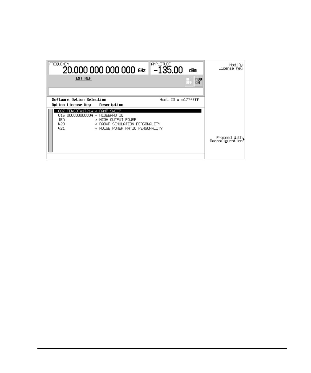
Basic Operation
Using the Web Server
2. Verify that the host ID shown on the display matches the host ID on the license key certificate.
The host ID is a unique number for every instrument. If the host ID on the license key certificate
does not match your instrument, the license key cannot enable the software option.
3. Verify that any required hardware is installed. Because some software options are linked to
specific hardware options, before the software option can be enabled, the appropriate hardware
option must be installed. For example, Option 420 (radar simulation modulation format) requires
that Option 601/602 (internal baseband generator) be installed. If the software option that you
intend to install is listed in a grey font, the required hardware may not be installed (look for an
X in the “Selected” column of the appropriate hardware option in the Hardware Options menu).
4. Enable the software option:
a. Highlight the desired option.
b. Press
Modify License Key, and enter the 12- character license key (from the license key certificate).
c. Verify that you want to reconfigure the signal generator with the new option:
Proceed With Reconfiguration > Confirm Change
The instrument enables the option and reboots.
Using the Web Server
You can communicate with the signal generator using the Web Server. This service uses TCP/IP
(Transmission Control Protocol/Internet Protocol) to communicate with the signal generator over the
internet.
The Web Server uses a client/server model where the client is the web browser on your PC or
workstation and the server is the signal generator. When you enable the Web Server, you can access
a web page that resides on the signal generator.
Chapter 2 67
Page 82

Basic Operation
Using the Web Server
The Web-Enabled PSG web page, shown in Figure 2-12, provides general information on your signal
generator and a means to control the instrument by using a remote front- panel interface or using
SCPI (Standard Communication for Programmable Instruments) commands. The web page also has
links to Agilent’s products, support, manuals, and website.
NOTE The Web Server service is compatible with the latest version of the Microsoft© Internet
Explorer web browser.
1
The Signal Generator Web Control menu button on the Web-Enabled PSG web page will access a
second web page. This web page, shown in Figure 2- 13, provides a virtual instrument interface that
can be used to control the signal generator. You can use the mouse to click on the signal generator’s
front panel hardkeys, softkeys and number pad. There is also a text box that can be used to send
SCPI commands to the instrument.
Activating the Web Server
Perform the following steps to access the Web Server.
1. Turn on the Web Server by pressing
2. Press the
3. Press the
Proceed With Reconfiguration softkey.
Confirm Change (Instrument will Reboot) softkey. The signal generator will reboot.
4. Launch your PC or workstation web browser.
5. Enter the IP address of the signal generator in the web browser address field. For example,
http://101.101.101.101. Replace 101.101.101.101 with your signal generator’s IP address. Press the
Enter key on the computer’s keyboard.
NOTE The IP (Internet Protocol) address can change depending on your LAN configuration.
Use the LAN Config Manual DHCP softkey to select a Manual or DHCP (dynamic host
communication protocol) LAN configuration. Refer to E8257D/67D PSG Signal Generators
Key Reference for more information.
6. Press the enter key on the computer’s keyboard. The web browser will display the signal
generator’s homepage as shown below in Figure 2- 12. This web page displays information about
the signal generator and provides access to Agilent’s website.
Utility > GPIB/RS–232 LAN > LAN Services Setup > Web S erver On.
1. Microsoft is a registered trademark of Microsoft Corp.
68 Chapter 2
Page 83

Figure 2-12 Signal Generator Web Page
Basic Operation
Using the Web Server
Chapter 2 69
Page 84

Basic Operation
Using the Web Server
7. Click the Signal Generator Web Control menu button on the left of the page. A new web page will
be displayed as shown below in Figure 2-13.
Figure 2-13 Web Page Front Panel
This web page remotely accesses all signal generator functions and operations. Use the mouse pointer
to click on the signal generator’s hardkeys and softkeys. The results of each mouse click selection will
be displayed on the web page. For example, click on the Frequency hardkey then use the front- panel
key pad to enter a frequency. You can also use the up and down arrow keys to increase or decrease
the frequency.
You can use the SCPI Command text box at the bottom of the front-panel display to send commands
to the signal generator. Enter a valid SCPI command, then click the SEND button. The results of the
command will be displayed on a separate web page titled, “SCPI Command Processed”. You can
continue using this web page to enter SCPI commands or you can return to the front panel web page.
NOTE It may be necessary to use the web browser Refresh function if the web page does not
update with new settings.
70 Chapter 2
Page 85

3 Basic Digital Operation
This chapter provides information on the functions and features available for the E8267D PSG vector
signal generator with Option 601 or 602.
• “Custom Modulation” on page 71
• “Arbitrary (ARB) Waveform File Headers” on page 72
• “Using the Dual ARB Waveform Player” on page 83
• “Using Waveform Markers” on page 88
• “Triggering Waveforms” on page 102
• “Using Waveform Clipping” on page 108
• “Using Waveform Scaling” on page 116
See also:
• “Custom Arb Waveform Generator” on page 143
• “Multitone Waveform Generator” on page 185
• “Two-Tone Waveform Generator” on page 195
Custom Modulation
For creating custom modulation, the signal generator offers two modes of operation: the Arb
Waveform Generator mode and the Real Time I/Q Baseband mode. The Arb Waveform Generator
mode has built-in modulation formats such as NADC or GSM and pre-defined modulation types such
as BPSK and 16QAM that can be used to create a signal. The Real Time I/Q Baseband mode can be
used to create custom data formats using built-in PN sequences or custom-user files along with
various modulation types and different built- in filters such as Gaussian or Nyquist.
Both modes of operation are used to build complex, digitally modulated signals that simulate
communication standards with the flexibility to modify existing digital formats, define or create
digitally modulated signals, and add signal impairments.
Chapter 3 71
Page 86

Basic Digital Operation
Arbitrary (ARB) Waveform File Headers
Custom Arb Waveform Generator
The signal generator’s Arb Waveform Generator mode is designed for out- of- channel test applications.
This mode can be used to generate data formats that simulate random communication traffic and can
be used as a stimulus for component testing. Other capabilities of the Arb Waveform Generator mode
include:
configuring single or multicarrier signals. Up to 100 carriers can be configured.
creating waveform files using the signal generator’s front panel interface.
The waveform files, when created as random data, can be used as a stimulus for component testing
where device performance such as adjacent channel power (ACP) can be measured. The
AUTOGEN_WAVEFORM file that is automatically created when you turn the Arb Waveform Generator
on can be renamed and stored in the signal generator’s non-volatile memory. This file can later be
loaded into volatile memory and played using the Dual ARB waveform player.
For more information, refer to the sections “Using the Dual ARB Waveform Player” on page 83 and
“Modes of Operation” on page 5.
Custom Real Time I/Q Baseband
The real- time mode simulates single- channel communication using user-defined modulation types
along with custom FIR filters, and symbol rates. Data can be downloaded from an external source
into PRAM memory or supplied as real time data using an external input. The Real Time I/Q
Baseband mode can also generate pre- defined data formats such as PN9 or FIX4. A continuous data
stream generated in this mode can be used for receiver bit error analysis. This mode is limited to a
single carrier. The Real Time I/Q Baseband mode:
has more data and modulation types available than the Arb Waveform Generator mode.
supports custom I/Q constellation formats.
has the capability to generate continuous PN sequences for bit error rate testing (BERT).
needs no waveform build time when signal parameters are changed.
For more information, refer to the custom arb section “Overview” on page 143, the custom real time
section “Overview” on page 165 and the section on “Digital Modulation” on page 6.
Arbitrary (ARB) Waveform File Headers
An ARB waveform file header enables you to save instrument setup information (key format settings)
along with a waveform. When you retrieve a stored waveform, the header information is applied so
that when the waveform starts playing, the dual ARB player is set up the same way each time.
Headers can also store a user-specified 32- character description of the waveform or sequence file.
A default header is automatically created whenever a waveform is generated, a waveform sequence is
created, or a waveform file is downloaded to the PSG (for details on downloading files, see the
E8257D/67D PSG Signal Generators Programming Guide).
The following signal generator settings are saved in a file header:
•ARB sample clock rate
• Runtime scaling (only in the dual ARB player)
72 Chapter 3
Page 87

Arbitrary (ARB) Waveform File Headers
First-Level Softkey Menu
(Some ARB formats
have a second page)
Basic Digital Operation
Marker settings and routing functions (page 88)
—Polarity
—ALC hold
—RF blanking
• High crest mode (only in the dual ARB player)
• Modulator attenuation
• Modulator filter
• I/Q output filter (used when routing signals to the rear panel I/Q outputs)
• Other instrument optimization settings (for files generated by the PSG) that cannot be set by the
user.
Creating a File Header for a Modulation Format Waveform
When you turn on a modulation format, the PSG generates a temporary waveform file
(AUTOGEN_WAVEFORM), with a default file header. The default header has no signal generator
settings saved to it.
This procedure, which is the same for all ARB formats, demonstrates how to create a file header for
a Custom digital modulation format.
1. Preset the signal generator.
2. Turn on the Custom modulation format:
Mode > Custom > ARB Waveform Generator > Digital Modulation Off On to On
Press
A default file header is created, and the temporary waveform file (AUTOGEN_WAVEFORM) plays.
Figure 3-1 shows the PSG’s display.
Figure 3-1 Custom Digital Modulation First-Level Softkey Menu
At this point, a default file header has been created, with default (unspecified) settings that do
not reflect the current signal generator settings for the active modulation. To save the settings for
Chapter 3 73
Page 88

Basic Digital Operation
Arbitrary (ARB) Waveform File Headers
the active modulation, you must modify the default settings before you save the header
information with the waveform file (see “Modifying Header Information in a Modulation Format”
on page 74).
NOTE Each time an ARB modulation format is turned on, a new temporary waveform file
(AUTOGEN_WAVEFORM) and file header are generated, overwriting the previous temporary
file and file header. Because all ARB formats use the same file name, this happens even if
the previous AUTOGEN_WAVEFORM file was created by a different ARB modulation format.
Modifying Header Information in a Modulation Format
This procedure builds on the previous procedure, explaining the different areas of a file header, and
showing how to access, modify, and save changes to the information.
In a modulation format, you can access a file header only while the modulation format is active (on).
This procedure uses the Custom digital modulation format. All ARB modulation formats and the dual
ARB player access the file header the same way, except that in some modulation formats, you may
have to go to page two of the first-level softkey menu.
1. From the first- level softkey menu (shown in Figure 3- 1 on page 73), open the Header Utilities
menu:
ARB Setup > Header Utilities
Press
Figure 3-2 shows the default header for the Custom digital modulation waveform. The
Saved Header Settings column, shows that the signal generator settings for the active format
are Unspecified, which means that no settings have been saved to the file header.
NOTE If a setting is unspecified in the file header, the signal generator’s current value for that
setting does not change when you select and play the waveform in the future.
The Current Inst. Settings column shows the current signal generator settings for the active
modulation. These settings become the saved header settings when they are saved to the file
header (as demonstrated in Step 2).
74 Chapter 3
Page 89

Figure 3-2 Custom Digital Modulation Default Header Display
Lets you enter/edit the
Description field
Clears the Saved Header
Settings column to the
default settings
Saves the Current Inst.
Settings column to the
Saved Header Settings
column
Current signal generator
settings
Page 1
Default Header Settings
Note:
Parameters that are inactive (such as
Runtime Scaling) can be set only in
the dual ARB player.
Page 2
Arbitrary (ARB) Waveform File Headers
Basic Digital Operation
2. Save the information in the Current Inst. Settings column to the file header:
Save Setup To Header.
Press
Both the Saved Header Settings column and the Current Inst. Settings column now display
the same settings; the Saved Header Settings column lists the settings saved in the file header.
The file header contains the following signal generator settings:
32- Character
Description:
Sample Rate: The ARB sample clock rate.
Runtime Scaling: The Runtime scaling value. Runtime scaling is applied in real- time while the waveform is playing.
Marker 1...4 Polarity: The marker polarity, positive or negative (described on page 102).
ALC Hold Routing: Which marker, if any, implements the PSG’s ALC hold function (described on page 90).
RF Blank Routing: Which marker, if any, implements the PSG’s RF blanking function (described on page 100).
I/Q Mod Filter: The I/Q modulator filter setting. The modulator filter affects the I/Q signal modulated onto the RF
I/Q Output Filter: The I/Q output filter setting. The I/Q output filter is used for I/Q signals routed to the rear panel
Mod Attenuation: The I/Q modulator attenuation setting.
Chapter 3 75
A description entered for the header, such as a the waveform’s function (saved/edited with the Edit
Description key, see Figure 3- 2 on page 75).
This setting can be changed only for files in the dual ARB player.
carrier.
I and Q outputs.
Page 90

Basic Digital Operation
Arbitrary (ARB) Waveform File Headers
3. Return to the ARB Setup menu: Press Return.
In the ARB Setup menu (shown in Figure 3-3), you can change the current instrument settings.
Figure 3-3 also shows the softkey paths used in steps four through nine.
4. Set the ARB sample clock to 5 MHz: Press
ARB Sample Clock > 5 > MHz.
5. Set the modulator attenuation to 15 dB:
More (1 of 2) > Modulator Atten n.nn dB Manual Auto to Manual > 15 > dB.
Press
6. Set the I/Q modulation filter to a through:
I/Q Mod Filter Manual Auto to Manual > Through.
Press
7. Set marker one to blank the RF output at the set marker point(s):
More (2 of 2) > Marker Utilities > Marker Routing > Pulse/RF Blank > Marker 1.
Press
For information on setting markers, see “Using Waveform Markers” on page 88.
8. Set the polarity of Marker 1 negative:
Return > Marker Polarity > Marker 1 Polarity Neg Pos to Neg.
Press
9. Return to the Header Utilities menu: Press
Return > Return > Header Utilities.
Notice that the Current Inst. Settings column now reflects the changes made to the current
signal generator setup in steps 4 through 8, but that the saved header values have not changed
(as shown in Figure 3- 4 on page 78).
10. Save the current settings to the file header: Press
Save Setup To Header softkey.
The settings from the Current Inst. Settings column now appear in the Saved Header
Settings column. The file header has been modified and the current instrument settings saved.
This is shown in Figure 3- 5 on page 78.
While a modulation format is active (is on), the waveform file (AUTOGEN_WAVEFORM) plays and you
can modify the header information within the active modulation format. Once you turn the
modulation format off, the header information is available only through the dual ARB player.
NOTE If you turn the modulation format off and then on, you overwrite the previous
AUTOGEN_WAVEFORM file and its file header. To avoid this, rename the file before you turn
the modulation format back on (see page 88).
Storing a waveform file (see page 87) stores the saved header information with the waveform.
76 Chapter 3
Page 91

Figure 3-3 ARB Setup Softkey Menu and Marker Utilities
Dual ARB Player softkey
(it does not appear in the ARB formats)
Arbitrary (ARB) Waveform File Headers
Basic Digital Operation
Chapter 3 77
Page 92
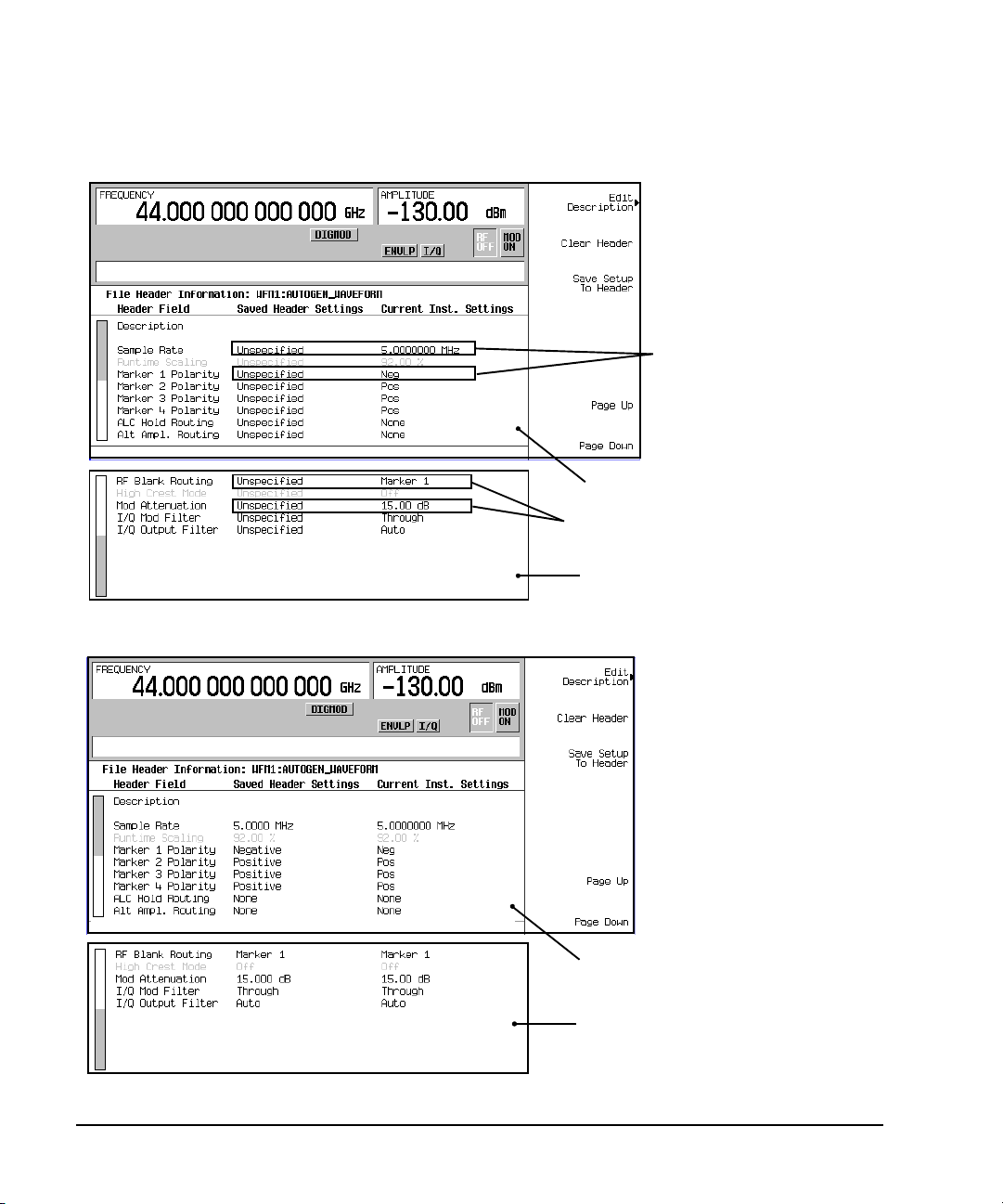
Basic Digital Operation
Values differ between
the two columns
Page 1
Page 2
Values differ between
the two columns
Page 1
Page 2
Arbitrary (ARB) Waveform File Headers
Figure 3-4 Differing Values between Header and Current Setting Columns
Figure 3-5 Saved File Header Changes
78 Chapter 3
Page 93

Arbitrary (ARB) Waveform File Headers
Basic Digital Operation
Storing Header Information for a Dual ARB Player Waveform Sequence
When you create a waveform sequence (described on page 85), the PSG automatically creates a
default file header, which takes priority over the headers for the waveform segments that compose
the waveform sequence. During a waveform sequence playback, the waveform segment headers are
ignored (except to verify that all required options are installed). When you store the waveform
sequence, its file header is stored with it.
Modifying and Viewing Header Information in the Dual ARB Player
Once a modulation format is turned off, the waveform file is available only to the dual ARB player.
This is also true for downloaded waveform files. Because of this, future edits to a waveform’s header
information must be performed using the dual ARB player.
To modify header information in the dual ARB player, the waveform file must be playing in the dual
ARB player (although you can view the header information in the dual ARB player without playing
the file)
You can reapply saved header settings by reselecting the waveform file for playback. When you do
this, the values from the Saved Header Settings column are applied to the PSG.
Modifying Header Information
All of the same header characteristics shown in “Modifying Header Information in a Modulation
Format” on page 74 are valid in the dual ARB player. This task guides you through selecting a
waveform file and accessing the header for the selected file, then refers you back to the
aforementioned procedure to perform the modifications.
1. Select a waveform:
a. Press
b. Using the arrow keys, highlight the desired waveform file.
c. Press the
2. Play the waveform: Press
3. Access the header: Press
4. Refer to “Modifying Header Information in a Modulation Format” to edit the header information:
• For a default header, read the information in step one on page 74, then perform the remaining
• To modify an existing file header, start with step three on page 76.
The rest of this section focuses on the additional file header operations found in the dual ARB
player.
Mode > Dual ARB > Select Waveform.
Select Waveform softkey.
ARB Off On to On.
ARB Setup > Header Utilities.
steps in the procedure.
Chapter 3 79
Page 94

Basic Digital Operation
Header editing softkeys
grayed-out
File header information and
current signal generator
settings
Page 1
Page 2
Note: When the dual ARB
player is off, the current
instrument settings column
does not update; the values
displayed may not be valid.
Arbitrary (ARB) Waveform File Headers
Viewing Header Information with the Dual ARB Player Off
One of the differences between a modulation format and the dual ARB player is that even when the
dual ARB player is off, you can view a file header. You cannot, however, modify the displayed file
header unless the dual ARB player is on, and the displayed header is selected for playback. With the
dual ARB player off, perform the following steps.
1. Select a waveform:
a. Press
Mode > Dual ARB > Select Waveform.
b. Highlight the desired waveform file.
c. Press the
2. Access the file header: Press
Select Waveform softkey.
ARB Setup > Header Utilities.
The header information is now visible in the PSG display. As shown in Figure 3- 6, the header
editing softkeys are grayed-out, meaning they are inactive.
Figure 3-6 Viewing Header Information
80 Chapter 3
Page 95

Arbitrary (ARB) Waveform File Headers
Current waveform file type
Waveform File Types
Table
Basic Digital Operation
Viewing Header Information for a Different Waveform File
While a waveform is playing in the dual ARB player, you can view the header information of a
different waveform file, but you can modify the header information only for the waveform that is
currently playing. When you select another waveform file, the header editing softkeys are grayed-out
(see Figure 3- 6). This task guides you through the available viewing choices.
1. View the waveform file list: Press
Mode > Dual ARB > ARB Setup > Header Utilities > View Different Header.
As shown in Figure 3- 7, there is an alphabetical list of waveform files in the table.
Figure 3-7 Waveform File List for Viewing a Different Header
2. View all waveform segments in non- volatile memory:
a. Press the
Catalog Type softkey. As shown in Figure 3- 7, you have a choice of three waveform file
types that can be displayed in the table accessed in step one.
NVWFM displays all waveform segments stored in non-volatile memory
Seq displays all waveform sequence files
WFM1 displays all waveform segments stored in volatile memory
b. Press the
3. View a waveform file’s header information: Highlight a file and press the
NVWFM softkey. The table displays the waveform files in non- volatile memory.
View Header softkey.
The header information for the selected waveform file appears in the PSG display. If there is a
waveform playing, its header information is replaced by this information, but the waveform
settings used by the signal generator do not change. To return to the header information for the
playing waveform, either press
View Header, or
press
Return > Header Utilities.
press
Chapter 3 81
View Different Header, select the current playing waveform file, and
Page 96

Basic Digital Operation
Header setting same as
preset setting
Header setting applied
Summary Display
The waveform is selected;
saved header settings are
applied.
Can change when a
waveform is selected
Summary Display
The waveform is not selected;
preset settings are applied.
Arbitrary (ARB) Waveform File Headers
Playing a Waveform File that Contains a Header
After a waveform file (AUTOGEN_WAVEFORM) is generated in a modulation format and the format is
turned off, the file becomes accessible to and can only be played back by the dual ARB player. This
is true for downloaded waveform files (downloading files is described in the E8257D/67D PSG Signal
Generators Programming Guide). When the waveform is selected for playback, the saved header
information is used by the signal generator. Some of these settings appear as part of the labels of the
softkeys used to set the parameters, and also appear on the dual ARB summary display (see Figure
3- 8).
NOTE The signal generator used to play back a stored waveform file must have the same options as
are required to generate the file.
For details on applying file header settings and playing back a waveform, see “Playing a Waveform”
on page 86.
To properly set up the instrument:
1. Select the waveform.
2. Modify the signal generator settings as desired.
3. Turn on the dual ARB.
Figure 3-8 File Header Settings
82 Chapter 3
Page 97
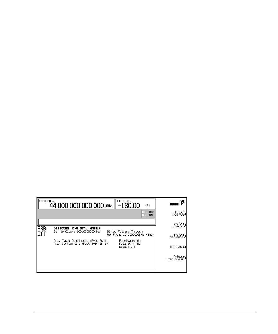
Using the Dual ARB Waveform Player
Basic Digital Operation
Using the Dual ARB Waveform Player
The dual arbitrary (ARB) waveform player is used to create, edit, and play waveform files. There are
two types of waveform files: segments and sequences. A segment is a waveform file that is created
using one of the signal generator’s pre- defined ARB formats. A sequence can be described as several
segments strung together to create one waveform file. Waveform files can also be created remotely
using another signal generator or using computer programs and downloaded to the PSG for playback
by the Dual ARB waveform player. For information on downloading waveforms, refer to the
E8257D/67D PSG Signal Generators Programming Guide.
A waveform file is automatically generated whenever an ARB modulation format is turned on. This
automatically generated file is named AUTOGEN_WAVEFORM. Because this default file name is
shared among all ARB formats, it must be renamed if you want to save the information. If the file is
not renamed, it will be overwritten when another ARB format is turned on.
The Dual ARB waveform player provides markers (page 88), triggering (page 102), and clipping
(page 108) capabilities.
Before you can work with any waveform file, it must reside in volatile memory. The signal generator
has two types of memory, WFM1 (volatile waveform memory) and NVWFM (non- volatile waveform
memory). A newly generated waveform file (AUTOGEN_WAVEFORM), created when the Arb Waveform
Generator is turned on, initially resides in WFM1. If you want to save this file, rename it and store
it in NVWFM. Load a stored waveform file from NVWFM into volatile memory (WFM1) where it can
be edited or played by the ARB waveform player. Refer to “Custom Modulation” on page 71 for more
information.
Accessing the Dual ARB Player
Press Mode > Dual ARB.
his first- level softkey menu is shown in the following figure. Most procedures start from this menu.
Chapter 3 83
Page 98

Basic Digital Operation
Using the Dual ARB Waveform Player
Creating Waveform Segments
There are two ways to provide waveform segments for use by the waveform sequencer. You can either
download a waveform via the remote interface, or generate a waveform using one of the ARB
modulation formats. For information on downloading waveforms via the remote interface, see the
E8257D/67D PSG Signal Generators Programming Guide.
A waveform sequence is made up of segments but can also contain other sequences. Any number of
segments, up to 32768, can be used to create a sequence. This limit count is determined by the
number of segments in the waveform sequence. Segments and sequences can be repeated within a
waveform sequence and the total of all segments and repeated segments cannot exceed the limit
count. The following diagram shows a waveform sequence made up of two sequences and three
segments. In this example the segment count is eleven.
Figure 3-9 Waveform Sequence Diagram
The following procedure describes how to create two waveform segments, then name and store them
in ARB memory. After you name and store the two waveform segments in ARB memory, you can use
them to build a waveform sequence, as described on page 85.
1. Generate the first waveform:
a. Press Preset >
b. Press
Tw o Ton e O f f O n to On, then to Off.
Mode > Two To n e > Alignment Left Cent Right to Right.
You turn off the Two Tone mode after generation because a waveform cannot be renamed as
a segment while it is in use.
This generates a two tone waveform with the tone on the right placed at the carrier frequency.
During waveform generation, the T-TONE and I/Q annunciators activate. The waveform is stored
in volatile memory, with the default file name AUTOGEN_WAVEFORM.
NOTE Because there can be only one AUTOGEN_WAVEFORM waveform in memory at any given time,
you must rename this file to clear the way for a second waveform.
84 Chapter 3
Page 99

Using the Dual ARB Waveform Player
Basic Digital Operation
2. Create the first waveform segment:
a. Press
Mode > Dual ARB > Waveform Segments > Load Store to Store.
b. Highlight the default segment AUTOGEN_WAVEFORM.
c. Press
Rename Segment > Editing Keys > Clear Text.
d. Enter a file name (for example, TTONE), and press Enter > Store Segment To NVWFM Memory.
This renames the waveform segment, and stores a copy in non volatile memory.
3. Generate the second waveform:
a. Press
Mode > Multitone > Initialize Table > Number Of Tones > 9 > Enter > Done.
b. Press Multitone Off On to On, then Off.
Remember that a waveform cannot be renamed as a segment while it is in use.
This generates a multitone waveform with nine tones. During waveform generation, the M-TONE
and I/Q annunciators activate. The waveform is stored in volatile memory with the default file
name AUTOGEN_WAVEFORM.
4. Create the second waveform segment:
Repeat Step 2, giving this segment a descriptive name (for example, MTONE).
Building and Storing a Waveform Sequence
This example shows how to build and edit a waveform sequence using the two waveform segments
created on page 84. To use a segment in a sequence, the segment must reside in volatile memory; for
information on loading waveform segments from non volatile to volatile memory, see page 87.
1. Select the waveform segments:
Define a sequence as one repetition of the two- tone waveform segment followed by one repetition
of the nine- tone multitone waveform segment.
a. Press
b. Highlight the a waveform segment (for example, TTONE) and press
c. Highlight a second waveform segment (for example, MTONE) and press
d. Press
2. Optional: Enable markers as desired for the segments in the new sequence: see page 97.
3. Name and store the waveform sequence to the Catalog of Seq Files in the memory catalog:
a. Press
b. Enter a file name (for example, TTONE+MTONE).
c. Press
Mode > Dual ARB > Waveform Sequences > Build New Waveform Sequence > Insert Waveform.
Insert Selected Waveform.
Insert Selected Waveform.
Done Inserting
Name and Store.
Enter.
Chapter 3 85
Page 100

Basic Digital Operation
Using the Dual ARB Waveform Player
Playing a Waveform
This procedure applies to playing either a waveform segment or a waveform sequence.
This example plays the waveform sequence created in the previous procedure.
1. Select a waveform sequence:
a. Press
Mode > Dual ARB > Select Waveform.
b. Highlight a waveform sequence (for this example, TTONE+MTONE) from the Sequence column of
the Select Waveform catalog, and press
Select Waveform.
The display shows the currently selected waveform
(for example, Selected Waveform: SEQ:TTONE+MTONE).
2. Generate the waveform:
ARB Off On to On.
Press
This plays the selected waveform sequence.
During the waveform sequence generation, the ARB and I/Q annunciators activate.
Editing a Waveform Sequence
This example shows how to edit waveform segments within a waveform sequence, and then save the
edited sequence under a new name. Within the editing display, you can change the number of times
each segment plays (the repetitions), delete segments, add segments, toggle markers (described on
page 97), and save changes.
NOTE If you do not store changes to the waveform sequence prior to exiting the waveform
sequence editing display, the changes are removed.
1. Press Waveform Se quences > Edit Selected Waveform Sequence, and highlight the first entry.
2. Press
3. Press
Edit Repetitions > 100 > Enter. The second segment is automatically selected.
Edit Repetitions > 200 > Enter.
4. Save the edited file as a new waveform sequence:
a. Press
b. Press
c. Press
Name And Store.
Editing Keys > Clear Text, then enter a new file name (for example, TTONE100+MTONE200).
Enter.
You have now changed the number of repetitions for each waveform segment entry from 1 to 100 and
200, respectively. The sequence has been stored under a new name to the Catalog of Seq Files in
the signal generator’s memory catalog.
For information on playing a waveform sequence, refer to page 86.
Adding Real-Time Noise to a Dual ARB Waveform
The signal generator with option 403 can apply AWGN (additive white gaussian noise) to a carrier in
real time while the modulating waveform file is being played by the Dual ARB waveform player. The
AWGN can be configured using front- panel softkeys. The
specify the amount of noise power relative to carrier power that is applied to the signal. The
86 Chapter 3
Carrier to Noise Ratio softkey allows you to
Carrier
 Loading...