


 Loading...
DR 400
5520/100
5520/200
User Manual
3231A EN 20150710 1114
2 | DR 400 | Contents
Contents
Legal Notice .......................................................................... |
5 |
Introduction .......................................................................... |
6 |
Introduction to this Manual ....................................... |
7 |
Scope of this Manual ...................................... |
8 |
Warnings, Cautions, Instructions and Notes .... |
|
9 |
|
Disclaimer ................................................... |
10 |
Introduction to DR 400 ............................................ |
10 |
Intended Use ............................................... |
11 |
Intended User .............................................. |
12 |
Configuration .............................................. |
13 |
Equipment Classification ............................. |
16 |
Options and Accessories ............................... |
17 |
Operation Controls ...................................... |
18 |
System Documentation ................................ |
27 |
Training ....................................................... |
28 |
Product Complaints ..................................... |
29 |
Compatibility ............................................... |
30 |
Compliance ................................................. |
31 |
Connectivity ................................................ |
33 |
Installation .................................................. |
34 |
Radiation Protection .................................... |
35 |
Labels .......................................................... |
40 |
Cleaning and Disinfecting ............................ |
46 |
Patient data security .................................... |
49 |
Maintenance ................................................ |
50 |
Environmental protection ............................ |
53 |
Safety Directions .......................................... |
54 |
Getting started ..................................................................... |
58 |
Starting the System .................................................. |
59 |
Basic workflow using the DR Detector ...................... |
60 |
Step 1: retrieve the patient info .................... |
61 |
Step 2: select the exposure ........................... |
62 |
Step 3: prepare the exposure ........................ |
63 |
Step 4: check the exposure settings .............. |
64 |
Step 5: execute the exposure ........................ |
65 |
Step 6: perform a quality control .................. |
66 |
Basic workflow using a CR cassette .......................... |
67 |
Step 1: retrieve the patient info .................... |
68 |
Step 2: select the exposure ........................... |
69 |
Step 3: prepare the exposure ........................ |
70 |
Step 4: check the exposure settings .............. |
71 |
Step 5: execute the exposure ........................ |
72 |
Step 6: repeat steps 2 to 5 for the next |
|
subexposures ............................................... |
73 |
3231A EN 20150710 1114
DR 400 | Contents | 3 |
|
Step 7: digitize the image ............................. |
74 |
Step 8: perform a quality control .................. |
75 |
X-Ray System Positioning ........................................ |
76 |
RAD Table Exposures ................................... |
77 |
Oblique Exposures ....................................... |
78 |
Lateral Exposures ........................................ |
79 |
RAD Wall Stand Exposures .......................... |
80 |
Guidelines for Pediatric Applications ....................... |
81 |
Stopping the System ................................................ |
83 |
Operation ............................................................................ |
84 |
Tube head display .................................................... |
85 |
RAD Table and X-Ray Tube Stand ............................ |
86 |
Positioning the X-Ray Tube Stand ................ |
88 |
Positioning the RAD Table ........................... |
91 |
Positioning the Bucky .................................. |
93 |
RAD Table Accessories ................................. |
94 |
RAD Wall Stand ....................................................... |
96 |
Positioning the RAD Wall Stand ................... |
98 |
RAD Wall Stand Accessories ....................... |
101 |
Bucky .................................................................... |
104 |
Bucky configuration ................................... |
106 |
Rotating the bucky ..................................... |
109 |
Loading of the bucky in the RAD Table ....... |
110 |
Loading of the bucky in the RAD Wall Stand .... |
|
111 |
|
Unloading of the bucky in the RAD Table |
... 112 |
Unloading of the bucky in the RAD Wall Stand . |
|
113 |
|
Centering and collimating .......................... |
114 |
Orientation of DX-D 10C, DX-D 10G in the bucky |
|
........................................................................ |
116 |
Grids ...................................................................... |
118 |
Grid focal distance color indication ............ |
119 |
Grid detection ............................................ |
120 |
Storage box for DR Detector and grids ................... |
121 |
Automatic Exposure Control (AEC) ........................ |
122 |
Manual Collimator ................................................. |
123 |
Dose Area Product Meter (DAP) ................. |
123 |
Automatic Collimator ............................................ |
125 |
Semi-automatic collimation mode ............. |
127 |
Manual collimation mode .......................... |
128 |
Dose Area Product Meter (DAP) ................. |
129 |
Effect of SID on patient dose .................................. |
130 |
X-Ray Generator Console ....................................... |
131 |
Starting and stopping the generator ........... |
132 |
X-ray tube start-up modes .......................... |
133 |
X-ray generator messages and warning signals . |
|
134 |
|
Exposure parameters ................................. |
139 |
Problem solving ................................................................. |
142 |
3231A EN 20150710 1114
4 | DR 400 | Contents
System messages ................................................... |
143 |
Restoring connection between generator and NX after |
|
generator failure .................................................... |
145 |
Automatic collimation always too wide or too narrow .. |
|
146 |
|
Empty Bucky Failure, Double Exposure Failure ...... |
147 |
NX does not connect to the generator due to ID tablet .. |
|
148 |
|
No table movement ................................................ |
149 |
DR Detector is Exceeding the Maximum Working |
|
Temperature .......................................................... |
150 |
DR Detector must be Recalibrated .......................... |
151 |
Technical Data ................................................................... |
152 |
DR 400 Technical Data .......................................... |
153 |
Environmental conditions .......................... |
154 |
Generator Technical Data ...................................... |
155 |
RAD Table and X-Ray Tube Stand Technical Data |
.. 157 |
Movement ranges ...................................... |
158 |
RAD Wall Stand Technical Data ............................. |
160 |
X-Ray Tube Technical Data .................................... |
162 |
Bucky Unit Technical Data ..................................... |
164 |
Automatic Exposure Control (AEC) Technical Data .... |
|
166 |
|
Ralco R221 Collimator Technical Data ................... |
167 |
Ralco R225 ACS Collimator Technical Data ........... |
168 |
Dose Area Product Meter (DAP) Technical Data |
.....169 |
DX-D Fixed DR Detector Technical Data ................. |
170 |
Portable DR Detector Technical Data ..................... |
172 |
NX Workstation Technical Data ............................. |
173 |
DR Generator Sync Box Technical Data .................. |
174 |
Remarks for HF-emission and immunity ............................ |
175 |
Remarks for HF-emission and immunity ................ |
176 |
Essential performance ........................................... |
182 |
Cables, transducers and accessories ....................... |
183 |
For type 5520/200 only ............................. |
185 |
Optional .................................................... |
185 |
Stray Radiation .................................................................. |
186 |
3231A EN 20150710 1114

DR 400 | Legal Notice | 5
Legal Notice
0413
 Agfa HealthCare NV, Septestraat 27, B-2640 Mortsel - Belgium
For more information on Agfa products and Agfa HealthCare products, please visit www.agfa.com.
Agfa and the Agfa rhombus are trademarks of Agfa-Gevaert N.V., Belgium or its affiliates. DR 400 is a trademark of Agfa HealthCare N.V., Belgium or one of its affiliates. All other trademarks are held by their respective owners and are used in an editorial fashion with no intention of infringement.
Agfa HealthCare N.V. makes no warranties or representation, expressed or implied, with respect to the accuracy, completeness or usefulness of the information contained in this document and specifically disclaims warranties of suitability for any particular purpose. Products and services may not be available for your local area. Please contact your local sales representative for availability information. Agfa HealthCare N.V. diligently strives to provide as accurate information as possible, but shall not be responsible for any typographical error. Agfa HealthCare N.V. shall under no circumstances be liable for any damage arising from the use or inability to use any information, apparatus, method or process disclosed in this document. Agfa HealthCare N.V. reserves the right to make changes to this document without prior notice. The original version of this document is in English.
Copyright 2015 Agfa HealthCare N.V
All rights reserved.
Published by Agfa HealthCare N.V.
B-2640 Mortsel - Belgium.
No part of this document may be reproduced, copied, adapted or transmitted in any form or by any means without the written permission of Agfa HealthCare N.V.
3231A EN 20150710 1114

6 | DR 400 | Introduction
Introduction
Topics:
•Introduction to this Manual
•Introduction to DR 400
3231A EN 20150710 1114

DR 400 | Introduction | 7
Introduction to this Manual
Topics:
•Scope of this Manual
•Warnings, Cautions, Instructions and Notes
•Disclaimer
3231A EN 20150710 1114
8 | DR 400 | Introduction
Scope of this Manual
This User Manual describes the features of the DR 400 System, an integrated X-Ray imaging system. It explains how the different components of the DR 400 System work together.
3231A EN 20150710 1114

DR 400 | Introduction | 9
Warnings, Cautions, Instructions and Notes
The following samples show how warnings, cautions, instructions and notes appear in this document. The text explains their intended use.
Warning: Warnings are directions which, if they are not followed, can cause fatal or serious injuries to a user, engineer, patient or any other person or can lead to a mistreatment.
Caution: Cautions are directions which, if they are not followed, can cause damage to the equipment described in this manual or any other equipment or goods and can cause environmental pollution.
Instruction: This sign is typically used in combination with the warning sign when providing a specific instruction. If it is followed exactly, it should avoid the subject of the warning.
Note: Notes provide advice and highlight unusual points. A note is not intended as an instruction.
3231A EN 20150710 1114

10 | DR 400 | Introduction
Disclaimer
Agfa assumes no liability for use of this document if any unauthorized changes to the content or format have been made.
Every care has been taken to ensure the accuracy of the information in this document. However, Agfa assumes no responsibility or liability for errors, inaccuracies or omissions that may appear in this document. To improve reliability, function or design Agfa reserves the right to change the product without further notice. This manual is provided without warranty of any kind, implied or expressed, including, but not limited to, the implied warranties of merchantability and fitness for a particular purpose.
Caution: In the United States, Federal law restricts this device to sale by or on the order of a physician.
Introduction to DR 400
Topics:
•Intended Use
•Intended User
•Configuration
•Equipment Classification
•Options and Accessories
•Operation Controls
•System Documentation
•Training
•Product Complaints
•Compatibility
•Compliance
•Connectivity
•Installation
•Radiation Protection
•Labels
•Cleaning and Disinfecting
•Patient data security
•Maintenance
•Environmental protection
•Safety Directions
3231A EN 20150710 1114
DR 400 | Introduction | 11
Intended Use
•The DR 400 system is a General Radiography X-ray imaging system used in hospitals, clinics and medical practices by physicists, radiographers and radiologists to make, process and view static X-ray radiographic images of the skeleton (including skull, spinal column and extremities), chest, abdomen and other body parts on adult or pediatric patients.
•Applications can be performed with the patient in the sitting, standing or lying position.
•This device is not intended for mammography applications.
3231A EN 20150710 1114
12 | DR 400 | Introduction
Intended User
This manual has been written for trained users of Agfa products and trained diagnostic X–Ray clinical personnel who have received proper training.
Users are those persons who actually handle the equipment and those who have authority over the equipment.
Before attempting to work with this equipment, the user must read, understand, note and strictly observe all warnings, cautions and safety markings on the equipment.
3231A EN 20150710 1114
DR 400 | Introduction | 13
Configuration
DR 400 is a configurable DR (Direct Radiography X-ray system) or CR (Computed Radiography) X-ray system.
The complete DR 400 consists of the following components:
•RAD Table with an integrated DX-D Fixed DR Detector or with a bucky. In the bucky a DR Detector or a CR cassette can be inserted.
•RAD Wall Stand with an integrated DX-D Fixed DR Detector or with a bucky. In the bucky a DR Detector or a CR cassette can be inserted.
•X-ray tube stand mounted on the RAD Table
•X-ray generator integrated in the RAD Table
•X-ray generator console
•X-ray tube with manual or automatic collimator
•NX image processing software on the NX workstation
•DR Generator Sync Box (depending on the configuration)
•Automatic Exposure Control (AEC)
•Dose Area Product Meter (DAP, optional)
Depending on the configuration the following components are also available:
• Portable DR Detector
DR 400 can be used in combination with:
•DX-G
•DX-M
•CR 30-X (5175/2XX)
•CR 30-Xm
•CR 10-X
•CR 12-X
•CR 15-X
DR 400 has three main configurations:
1.DR configuration with X-ray exposure parameter control on the NX workstation.
2.CR configuration with X-ray exposure parameter control on the NX workstation.
3.Mixed DR and CR configuration with X-ray exposure parameter control on the NX workstation.
X-ray parameters are controlled using the Software Console on the NX workstation.
The Software Console is available on the NX workstation, to synchronize the X-ray exposure parameters between the NX application and the generator.
Other configurable features include:
• Tube head display with controls for X-ray exposure parameters
3231A EN 20150710 1114
14 | DR 400 | Introduction
•Position tracking for keeping constand SID on table and wall stand
•Bucky with automatic cassette size sensing (ACSS) and automatic collimator
|
|
|
|
|
|
|
|
|
|
|
|
|
|
|
|
|
|
|
|
|
|
|
|
|
|
|
|
|
|
|
|
|
|
|
|
|
|
|
|
|
|
|
|
|
|
|
|
|
|
|
|
|
|
|
|
|
|
|
|
|
|
|
|
|
|
|
|
|
|
1 |
2 |
3 |
4 |
5 |
6 |
||||
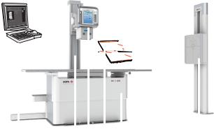
1.NX workstation
2.X-ray tube stand mounted on RAD Table
3.X-ray tube with collimator and tube head display
4.Portable DR Detector
5.RAD Table with integrated generator
6.RAD Wall Stand
Figure 1: DR 400 configuration for DR
Topics:
•Applied Parts
Applied Parts
Applied Parts refer to parts of the medical electrical equipment that in normal use necessarily comes into physical contact with the patient for the equipment to perform its function. This system includes the following Applied Parts:
Topics:
•RAD Table
•RAD Wall Stand
•DR Detector
RAD Table
•Table top of the RAD Table
•Patient hand grips (optional)
•Lateral cassette holder (optional)
3231A EN 20150710 1114
DR 400 | Introduction | 15
•Mattress (optional)
•Compression belt (optional)
RAD Wall Stand
•Front panel of the RAD Wall Stand
•Overhead arm support (optional)
•Patient hand grips (optional)
DR Detector
• DR Detector
3231A EN 20150710 1114
16 | DR 400 | Introduction
Equipment Classification
Per EN/IEC 60601-1:2005, EN/IEC 60601-2-54:2009, this device is classified as following:
Table 1: Equipment classification
Class I equipment |
Equipment in which protection against electric |
|
shock does not rely on basic insulation only, but |
|
includes a fixed connection to mains power with |
|
protective earth conductor. |
|
|
Type B equipment |
A Type B piece of equipment is one that provides a |
|
particular degree of protection against electric |
|
shock particularly regarding allowable leakage |
|
current and reliability of the protective earth |
|
protection. |
|
|
Water ingress |
IP10 |
|
This device does not have protection against |
|
ingress of water. |
|
|
Cleaning |
See section on cleaning and disinfecting. |
|
|
Disinfection |
See section on cleaning and disinfecting. |
|
|
Flammable anesthetics |
This device is not suitable for use in the presence of |
|
a flammable anesthetic mixture with air, or in |
|
presence of a flammable anesthetic mixture with |
|
oxygen or nitrous oxide. |
|
|
Operation |
Continuous operation. |
|
|
Related Links
Cleaning and Disinfecting on page 46
3231A EN 20150710 1114
DR 400 | Introduction | 17
Options and Accessories
The system is delivered with a set of labels. When using multiple DR Detectors, on the labels a nickname is written to identify the DR Detector. An identical label is attached to the bucky of the X-ray system to identify the dedicated workspace of each DR Detector.
For information on options and accessories of the DR Detector, refer to the user manual of the DR Detector.
Related Links
RAD Table Accessories on page 94
RAD Wall Stand Accessories on page 101
3231A EN 20150710 1114
18 | DR 400 | Introduction
Operation Controls
Topics:
•RAD Table
•RAD Wall Stand
•Control Panel of the X-Ray Tube Stand
•NX Application on the NX Workstation
•Software Console
•DR Detector Switch
•X-ray generator mini console
•Manual collimator
•Automatic collimator
•DR Detector
•Emergency stop button
•Emergency shutdown power switch
RAD Table
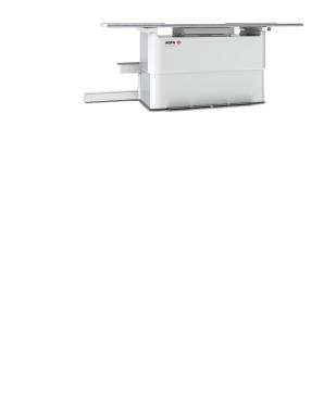
The RAD Table is used for positioning of the patient lying or sitting over the detector or the cassette in the bucky for exposure. 
The RAD Table supports the patient and the detector or the cassette for free exposure.
Figure 2: RAD Table
Related Links
RAD Table and X-Ray Tube Stand
RAD Wall Stand
The RAD Wall Stand is used for positioning of patients standing upright or sitting towards the bucky for exposure.
3231A EN 20150710 1114

DR 400 | Introduction | 19
Figure 3: RAD Wall Stand with vertical bucky
Related Links
RAD Wall Stand on page 96
Control Panel of the X-Ray Tube Stand
Figure 4: Control Panel of the X-Ray Tube Stand with tube head display (controls for X-ray tube position and for X-ray exposure parameters)
Figure 5: Control Panel of the X-Ray Tube Stand with X-ray tube angle display
Related Links
RAD Table and X-Ray Tube Stand on page 86
3231A EN 20150710 1114


DR 400 | Introduction | 21
Figure 8: Software Console
DR Detector Switch
The DR Detector Switch is available in the device status frame of the Software Console.
The DR Detector Switch shows which DR Detector is active and shows its status. The DR Detector Switch can be used to activate another DR Detector. The DR Detector Switch can be switched to CR, depending on the configuration.
Figure 9: DR Detector Switch
DR Detector Status
Battery status icon
Meaning |
Full |
Medium |
Low |
Empty |
Connection status icon (wifi/ wired)
3231A EN 20150710 1114

22 | DR 400 | Introduction
Meaning |
|
Good |
Low |
|
Bad |
|
Wired DR Detector |
||
|
|
|
|
|
|
|
|
|
|
|
|
|
|
|
|
|
|
|
|
DR detector |
|
|
|
|
|
|
|
|
? |
status icon |
|
|
|
|
|
|
|
|
|
|
|
(blinking) |
|
|
|
|
|
|
|
|
|
|
|
|
|
|
|
||
Meaning |
Ready |
Initializing |
Error |
|
Sleep |
|
One DR detector |
||
|
|
exposure |
|
|
|
|
|
must be selected |
|
|
|
|
|
|
|
|
|
|
|
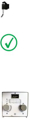
X-ray generator mini console
The X-ray generator mini console is available in the operator room.
1 2 3
7
5
4 |
6 |
8 |
1.Power ON button
2.Power ON indicator
3.Power OFF button
4.Press and hold to prepare for exposure
5.Prepare ready indicator
6.Press and hold to start the exposure
7.Radiation indicator
8.Exposure button
Figure 10: X-ray generator mini console
Exposure button
Preparing for exposure
Press the exposure button down to the first pressure point and hold it for approximately 0.5 s to 2 s.
3231A EN 20150710 1114
DR 400 | Introduction | 23
The X-ray tube is prepared for performing an exposure.
Starting the exposure
Before starting the exposure:
1.Check if the exposure settings displayed on the console are suitable for the exposure.
2.Check the Ready for Exposure status.
Press the exposure button down fully and keep it pressed until the exposure has ended.
The radiation indicator on the control console lights up and a signal sounds to indicate the exposure.
Note: Letting the exposure button go ends the exposure immediately and the exposure can be underexposed.
Manual collimator
The collimator sets the exposure field and displays it by means of a light field.
The collimator provides X-ray filtering using the integrated filters or by inserting a filter in the rails.
A DAP meter (Dose Area Product Meter) can be mounted on the collimator by inserting it in the rails.
Figure 11: Collimator
Related Links
Ralco R221 Collimator Technical Data on page 167
Automatic collimator
The collimator sets the exposure field and displays it by means of a light field.
3231A EN 20150710 1114

24 | DR 400 | Introduction
The collimator provides X-ray filtering using the integrated filters or by inserting a filter in the rails.
An integrated DAP meter (Dose Area Product Meter) in the collimator is available as an option.
Figure 12: Collimator
Related Links
Automatic Collimator on page 125
Automatic Cassette Size Sensing on page 114
Ralco R225 ACS Collimator Technical Data on page 168
DR Detector
When performing an exposure, keep in mind the following detector orientation aids:
1.Tube side
2.Patient orientation marker
For an overview of the operation controls of the DR Detector, refer to the user manual of the DR Detector.
The DR Detector may come in contact with the patient.
Note: DR Detectors that operate wireless contain an RF transmitter. For detailed information, refer to the DR Detector User Manual.
3231A EN 20150710 1114
DR 400 | Introduction | 25
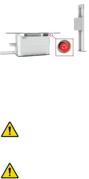
Emergency stop button
Figure 13: Emergency stop button
If a system malfunction causes an emergency situation involving the patient, operating personnel or any system component, activate the emergency stop on the RAD Table. All motor driven movements will be stopped.
Motor driven movements:
•RAD Table
•RAD Wall Stand
•X-ray tube stand
To allow motorized movements again, turn the cap of the emergency switch in clockwise direction (default position).
Warning: The emergency stop button does not switch off the voltage in the X-ray system.
Emergency shutdown power switch
Use the emergency shutdown power switch, if a dangerous situation cannot be eliminated by pressing the emergency stop button.
Warning: Use the emergency shutdown power switch in case of danger to patients, operators, third parties, or one of the units. The entire system will be shut down and the power supply will be disconnected.
The emergency shutdown power switch for the room is typically located on the wall and easy to access, often close to the power off switch of the X-ray system. It is installed and labeled by customer.
3231A EN 20150710 1114

26 | DR 400 | Introduction
Warning: It must be ensured that the emergency switches are always freely accessible.
3231A EN 20150710 1114
DR 400 | Introduction | 27
System Documentation
The DR 400 user documentation consists of
• DR 400 User Documentation CD (digital media)
•NX User Documentation CD (digital media) The DR 400 User Documentation CD contains:
•DR 400 User Manual (this document)
•DX-D Software Console, DR Tube Head Display User Manual, document 0389
•User manuals for the supported DR Detectors
•DX-D DR Detector Calibration Key User manual, document 0134
Other documentation available on the DR 400 User Documentation CD:
•DAP Datasheet
•X-ray Tube Documentation
•Collimator Datasheet
•AEC Datasheet
•X-ray Generator User Manual
•Test Report for IEC60601-1-3
•Test Report for DIN6868-150
3231A EN 20150710 1114
28 | DR 400 | Introduction
Training
The user must have received adequate training on the safe and effective use of the system before attempting to work with it. Training requirements may vary from country to country. The user must make sure that training is received in accordance with local laws or regulations that have the force of law. Your local Agfa or dealer representative can provide further information on training.
The user must note the following information in the system documentation:
•Intended Use.
•Intended User.
•Safety Directions.
3231A EN 20150710 1114
DR 400 | Introduction | 29
Product Complaints
Any health care professional (for example a customer or a user) who has any complaints or has experienced any dissatisfaction with the quality, durability, reliability, safety, effectiveness, or performance of this product must notify Agfa.
If the device malfunctions and may have caused or contributed to a serious injury, Agfa must be notified immediately by telephone, fax or written correspondence to the following address:
Agfa Service Support - local support addresses and phone numbers are listed on www.agfa.com
Agfa - Septestraat 27, 2640 Mortsel, Belgium Agfa - Fax +32 3 444 7094
3231A EN 20150710 1114
30 | DR 400 | Introduction
Compatibility
The system must only be used in combination with other equipment or components if these are expressly recognized by Agfa as compatible. A list of such equipment and components is available from Agfa service on request.
Changes or additions to the equipment must only be carried out by persons authorized to do so by Agfa. Such changes must comply with best engineering practice and all applicable laws and regulations that have the force of law within the jurisdiction of the hospital.
3231A EN 20150710 1114
Loading...