


:ANAPURNA XL²
OPERATOR MANUAL
version 1.0
AB]
:ANAPURNA XL² |
OPERATOR MANUAL |
|
|
TABLE OF CONTENTS |
|
1. Safety Instructions ..................................................................................................................................................................... |
3 |
|
2. Printer Overview and Features................................................................................................................................................. |
4 |
|
2.1 |
Front view, parts & locations ........................................................................................................................................ |
4 |
2.2 |
Rear view, parts & locations.......................................................................................................................................... |
5 |
2.3 |
Head Carriage view, parts.............................................................................................................................................. |
7 |
2.4 |
Signal tower ..................................................................................................................................................................... |
7 |
3. Head Technology........................................................................................................................................................................ |
8 |
|
4. :Anapurna UV Curable Ink......................................................................................................................................................... |
9 |
|
4.1 |
General information........................................................................................................................................................ |
9 |
4.2 |
Color gamut...................................................................................................................................................................... |
9 |
4.3 |
Packing.............................................................................................................................................................................. |
9 |
5. Ink Circuit ................................................................................................................................................................................. |
10 |
|
5.1 |
Main ink tanks .............................................................................................................................................................. |
10 |
5.2 |
Auto ink supply............................................................................................................................................................. |
10 |
5.3 |
Sub Ink Tank.................................................................................................................................................................. |
11 |
5.4 |
The 2-way valves.......................................................................................................................................................... |
12 |
5.5 |
Negative Pressure Setting .......................................................................................................................................... |
13 |
5.6 |
Waste tank..................................................................................................................................................................... |
14 |
6. UV Curing System.................................................................................................................................................................... |
15 |
|
6.1 |
General information..................................................................................................................................................... |
15 |
6.2 |
Curing setup and sequences ...................................................................................................................................... |
15 |
6.3 |
Uniand Bi-directional printing................................................................................................................................. |
16 |
7. Printing Table........................................................................................................................................................................... |
17 |
|
7.1 |
General information..................................................................................................................................................... |
17 |
7.2 |
Belt Tension control..................................................................................................................................................... |
18 |
7.3 |
Maintenance.................................................................................................................................................................. |
18 |
7.4 |
Replacement................................................................................................................................................................. |
20 |
8. Maintenance............................................................................................................................................................................. |
21 |
|
8.1 |
General information..................................................................................................................................................... |
21 |
8.2 |
Daily Maintenance – Nozzle check/purge.............................................................................................................. |
22 |
8.3 |
Weekly Maintenance................................................................................................................................................... |
25 |
8.4 |
Long Stand Still............................................................................................................................................................. |
26 |
8.5 |
Bleeding air out of the ink filters .............................................................................................................................. |
28 |
9. Media Setup ............................................................................................................................................................................. |
29 |
|
9.1 |
Roll to Roll..................................................................................................................................................................... |
29 |
|
9.1.1 Auto Feed System ............................................................................................................................................ |
29 |
|
9.1.2 Take-Up control system .................................................................................................................................. |
30 |
|
9.1.3 Roll Alignment.................................................................................................................................................. |
30 |
|
9.1.4 Vacuum.............................................................................................................................................................. |
30 |
9.2 |
Rigid Media.................................................................................................................................................................... |
31 |
|
9.2.1 Rigid Support tables......................................................................................................................................... |
31 |
|
9.2.2 Rigid Alignment................................................................................................................................................ |
31 |
|
9.2.2.1 Media Register Pins......................................................................................................................... |
31 |
|
9.2.2.2 Top and Left Margin Setup............................................................................................................. |
32 |
|
9.2.3 Vacuum.............................................................................................................................................................. |
33 |
9.3 |
Media Tension Bars...................................................................................................................................................... |
33 |
10. Head Base – Height Control................................................................................................................................................ |
34 |
|
10.1 Automatic “Head Base Height” Setup.................................................................................................................... |
34 |
|
11. :Anapurna Control Program................................................................................................................................................. |
36 |
|
11.1 Control Program Menu.............................................................................................................................................. |
36 |
|
11.2 Setup Parameter Menu ............................................................................................................................................. |
37 |
|
11.3 Test Menu.................................................................................................................................................................... |
46 |
|
12. Printing an image.................................................................................................................................................................. |
48 |
|
12.1 Preparing an image.................................................................................................................................................... |
48 |
|
12.2 Preparing the :Anapurna........................................................................................................................................... |
48 |
|
12.3. Printing the image.................................................................................................................................................... |
49 |
|
12.4. Cancel a print............................................................................................................................................................. |
50 |
|
12.5. Purge function on the printing ............................................................................................................................... |
50 |
|
13. Tips & Tricks........................................................................................................................................................................... |
51 |
|
AB]]]]]]]]]]]]]]]]]]]]]]]]]]]]]]]]]]]]]]]]]]]]]]]]]]]]]]]]]]]]]]]]]]]]]]]]]]]]]]]]]]]]]]]]]]]]]]]]]]]]]]]]]]]]]]]]]]]]]]]]]]]]]]]]]]]]]]]]]]]]]]]]]]]]]]]]]]]]]]]]]]]]]]]]]]]]]]]]]]]]]]]]]]]]]]]]]]]]]]]]]]]]]]]]]]]]]]]]]]]]]]]]]]]]2] |
8/08/2008] |
|

:ANAPURNA XL² |
OPERATOR MANUAL |
1. Safety Instructions.
IMPORTANT
Be sure to follow all instructions and warnings in this manual when using the equipment.
 WARNING
Do NOT look directly into the UV light when printing, and don’t expose your skin directly to the UV light. If you need to look at the direction of the light, wear protective glasses or look through the front cover glas.
 WARNING
UV ink contains chemicals, when handling the ink, wear protective gloves to protect your skin, and protective glasses. Should the ink come in contact with your skin, wash with water immediately.
IMPORTANT
The Anapurna engines are equipped with an exhaust system to extract the heat and the ozone gas, which is built up by the curing process.
Make sure the exhaust system leads to the outside air.
|
|
|
AB]]]]]]]]]]]]]]]]]]]]]]]]]]]]]]]]]]]]]]]]]]]]]]]]]]]]]]]]]]]]]]]]]]]]]]]]]]]]]]]]]]]]]]]]]]]]]]]]]]]]]]]]]]]]]]]]]]]]]]]]]]]]]]]]]]]]]]]]]]]]]]]]]]]]]]]]]]]]]]]]]]]]]]]]]]]]]]]]]]]]]]]]]]]]]]]]]]]]]]]]]]]]]]]]]]]]]]]]]]]]]]]]]]]]3] |
8/08/2008] |
|

:ANAPURNA XL² |
OPERATOR MANUAL |
2. Printer Overview and Features.
System Dimensions:
ANAPURNA XL² Max. media width: 2.5m (printable width: 2.48m)
2.1. Front view, parts & locations
AB]]]]]]]]]]]]]]]]]]]]]]]]]]]]]]]]]]]]]]]]]]]]]]]]]]]]]]]]]]]]]]]]]]]]]]]]]]]]]]]]]]]]]]]]]]]]]]]]]]]]]]]]]]]]]]]]]]]]]]]]]]]]]]]]]]]]]]]]]]]]]]]]]]]]]]]]]]]]]]]]]]]]]]]]]]]]]]]]]]]]]]]]]]]]]]]]]]]]]]]]]]]]]]]]]]]]]]]]]]]]]]]]]]]]4] |
8/08/2008] |

:ANAPURNA XL² |
OPERATOR MANUAL |
2.2. Rear view, parts & locations
AB]]]]]]]]]]]]]]]]]]]]]]]]]]]]]]]]]]]]]]]]]]]]]]]]]]]]]]]]]]]]]]]]]]]]]]]]]]]]]]]]]]]]]]]]]]]]]]]]]]]]]]]]]]]]]]]]]]]]]]]]]]]]]]]]]]]]]]]]]]]]]]]]]]]]]]]]]]]]]]]]]]]]]]]]]]]]]]]]]]]]]]]]]]]]]]]]]]]]]]]]]]]]]]]]]]]]]]]]]]]]]]]]]]]]5] |
8/08/2008] |
:ANAPURNA XL² |
OPERATOR MANUAL |
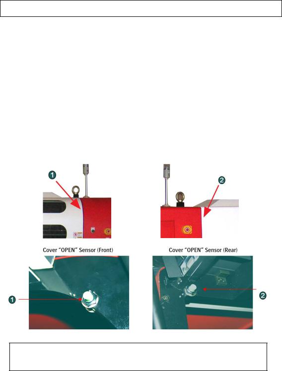
COVER “OPEN” SENSOR
This engine is equipped with a “safety sensor” on the Front and Rear cover. Carrige movement and printing can only be done with covers closed.
.
1.When carriage is waiting: (Purge or Home)
When a cover is “open”, you will see the “door open error” on the screen, and the carriage will not move to Home or Purge if requested.
2.During printing:
When you open the cover at this stage, the PRINT will be CANCELLED and the UV lamp shutter will be closed automatically.
OPENING THE COVER DURING PRINTING, WILL RESULT IN A CANCELLED PRINT !
ONLY OPEN THE DOOR IN EMERGENCY SITUATIONS !
AB]]]]]]]]]]]]]]]]]]]]]]]]]]]]]]]]]]]]]]]]]]]]]]]]]]]]]]]]]]]]]]]]]]]]]]]]]]]]]]]]]]]]]]]]]]]]]]]]]]]]]]]]]]]]]]]]]]]]]]]]]]]]]]]]]]]]]]]]]]]]]]]]]]]]]]]]]]]]]]]]]]]]]]]]]]]]]]]]]]]]]]]]]]]]]]]]]]]]]]]]]]]]]]]]]]]]]]]]]]]]]]]]]]]]6] |
8/08/2008] |

:ANAPURNA XL² |
OPERATOR MANUAL |
2.3. Head Carriage view, parts
2.4. Signal tower
AB]]]]]]]]]]]]]]]]]]]]]]]]]]]]]]]]]]]]]]]]]]]]]]]]]]]]]]]]]]]]]]]]]]]]]]]]]]]]]]]]]]]]]]]]]]]]]]]]]]]]]]]]]]]]]]]]]]]]]]]]]]]]]]]]]]]]]]]]]]]]]]]]]]]]]]]]]]]]]]]]]]]]]]]]]]]]]]]]]]]]]]]]]]]]]]]]]]]]]]]]]]]]]]]]]]]]]]]]]]]]]]]]]]]]7] |
8/08/2008] |
:ANAPURNA XL² |
OPERATOR MANUAL |
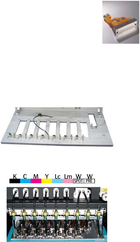
3. Head technology.
Color heads:
-Spectra Galaxy 256/50 AAA JA (Jetting Assembly)
•Calibrated Drop Size: 50 pl
•256 addressable jetting nozzles, single line
•Nozzle spacing: 256 microns (0,010”)
•Intrinsic resolution: 100 dpi
White heads:
-Spectra Galaxy 256/80 AAA JA (Jetting Assembly)
•Calibrated Drop Size: 75 pl
•256 addressable jetting nozzles, single line
•Nozzle spacing: 256 microns (0,010”)
•Intrinsic resolution: 100 dpi
-8 JA mounted in head base plate
•7 heads in line
•1 head mounted in front of the other heads, used for “Pre-White”.
-Supported Color mode – fixed
-Color Sequence:
AB]]]]]]]]]]]]]]]]]]]]]]]]]]]]]]]]]]]]]]]]]]]]]]]]]]]]]]]]]]]]]]]]]]]]]]]]]]]]]]]]]]]]]]]]]]]]]]]]]]]]]]]]]]]]]]]]]]]]]]]]]]]]]]]]]]]]]]]]]]]]]]]]]]]]]]]]]]]]]]]]]]]]]]]]]]]]]]]]]]]]]]]]]]]]]]]]]]]]]]]]]]]]]]]]]]]]]]]]]]]]]]]]]]]]8] |
8/08/2008] |

:ANAPURNA XL² |
OPERATOR MANUAL |
4. :Anapurna UV Curable Ink.
4.1. General information
-The :Anapurna UV curable ink is specially developed for best performance on the :Anapurna engine.
-Sharp printing, vibrant colors on a wide range of media
-Ensures dry and instant ready prints with excellent outdoor durability
-Use of light inks
•Enhance apparent output resolution by using Light Cyan and Light Magenta
•Results in smooth highlights
-Ink usage: ± 10ml/m², all colors together (6)
4.2. Color gamut
-Agfa Inks tuned towards the ISO Standard 12647 (2004)
-Calculated nr of colors (Volume calculated within Monaco CMS)
-ISO Standard 12647: 770.000 colors
-:Anapurna Ink on :Anapurna printing in:
»6 pass : 830.000 colors
»8 pass : 850.000 colors
»12 pass : 1.080.000 colors
»16 pass :
4.3. Packing
- 1L bottle, packed per 4
:Anapurna Cyan |
:Anapurna Magenta |
:Anapurna Light Cyan |
:Anapurna Light Magenta |
:Anapurna Yellow |
:Anapurna White |
:Anapurna Black |
:Anapurna Cleaning Solution |
AB]]]]]]]]]]]]]]]]]]]]]]]]]]]]]]]]]]]]]]]]]]]]]]]]]]]]]]]]]]]]]]]]]]]]]]]]]]]]]]]]]]]]]]]]]]]]]]]]]]]]]]]]]]]]]]]]]]]]]]]]]]]]]]]]]]]]]]]]]]]]]]]]]]]]]]]]]]]]]]]]]]]]]]]]]]]]]]]]]]]]]]]]]]]]]]]]]]]]]]]]]]]]]]]]]]]]]]]]]]]]]]]]]]]]9] |
8/08/2008] |

:ANAPURNA XL² |
OPERATOR MANUAL |
5. Ink Circuit.
5.1. Main ink tanks
-The main ink tanks are located on the right side of the engine.
-1.6 liter per color
-Low level detection at 0.3lm, enough
to finish the currently printing job. Audible & visual alarm on the Signal tower.
-Ink can be refilled in while printing
-White ink tank has a continuous working stirring rod inside.
-Tanks:
 WARNING
ONLY refill with the 1liter bottle, when the low level alarm goes off.
At that point, you can pour in a complete 1L bottle, and you won’t have any left over ink remaining in the bottle!!
5.2. Auto ink supply
-From the ink tank, ink is pumped into the “Sub ink tank”, which is positioned on the Head Carriage.
-The Sub ink tank is temperature controlled, and has a content of 35ml per color
AB]]]]]]]]]]]]]]]]]]]]]]]]]]]]]]]]]]]]]]]]]]]]]]]]]]]]]]]]]]]]]]]]]]]]]]]]]]]]]]]]]]]]]]]]]]]]]]]]]]]]]]]]]]]]]]]]]]]]]]]]]]]]]]]]]]]]]]]]]]]]]]]]]]]]]]]]]]]]]]]]]]]]]]]]]]]]]]]]]]]]]]]]]]]]]]]]]]]]]]]]]]]]]]]]]]]]]]]]]]]]]]]]]]]]10] |
8/08/2008] |
:ANAPURNA XL² OPERATOR MANUAL
5.3. Sub Ink Tank and head base temperatures
- Temperature setting “Sub Ink Tank”
Color: |
40°C |
White Ink: |
40°C when in use (up to max 45°C) |
|
25°C when not in use |
-Temperature setting “Headbase plate” : 40°C
-Read out:
- How to make changes:
At this stage, you also need to Press the “AT” button, to close the procedure.
AB]]]]]]]]]]]]]]]]]]]]]]]]]]]]]]]]]]]]]]]]]]]]]]]]]]]]]]]]]]]]]]]]]]]]]]]]]]]]]]]]]]]]]]]]]]]]]]]]]]]]]]]]]]]]]]]]]]]]]]]]]]]]]]]]]]]]]]]]]]]]]]]]]]]]]]]]]]]]]]]]]]]]]]]]]]]]]]]]]]]]]]]]]]]]]]]]]]]]]]]]]]]]]]]]]]]]]]]]]]]]]]]]]]]]11] |
8/08/2008] |

:ANAPURNA XL² |
OPERATOR MANUAL |
5.4. The 2-Way valves
-Normal printing:
-The color valves are positioned in the “I” direction. The ink can flow to the head.
-Purging the heads:
-In case of clogged nozzles, or misfiring nozzles; Push the “Purge” button at very short intervals, this will cause ink flowing through the heads, this will un-clog the missing nozzles.
(make sure the Grid is pushed to the back)
-Cleaning the heads with Cleaning solution:
-The color valves must be “closed”, set them to
the “S” direction. Now, the ink flow to the heads is closed. Open the Cleaning Solution “control valve” on the right. When you now push the “Solution-Purge” button on
the BACK of the shuttle, Cleaning solution will flow through your heads to un-clog the missing nozzles.
THE APPROPRIATE WAY OF WORKING, FOR PERFORMING A NOZZLE CHECK,
AND JUDGING MISFIRING NOZZLES,
CAN BE FOUND IN THE MAINTENANCE CHAPTER.
AB]]]]]]]]]]]]]]]]]]]]]]]]]]]]]]]]]]]]]]]]]]]]]]]]]]]]]]]]]]]]]]]]]]]]]]]]]]]]]]]]]]]]]]]]]]]]]]]]]]]]]]]]]]]]]]]]]]]]]]]]]]]]]]]]]]]]]]]]]]]]]]]]]]]]]]]]]]]]]]]]]]]]]]]]]]]]]]]]]]]]]]]]]]]]]]]]]]]]]]]]]]]]]]]]]]]]]]]]]]]]]]]]]]]]12] |
8/08/2008] |

:ANAPURNA XL² |
OPERATOR MANUAL |
5.5. Negative pressure setting
- Ink supply by means of negative pressure:
By means of negative pressure, the ink is kept in the print heads. A too high setting will cause missing nozzles, or no ink firing at all. When the pressure is too low, the ink will leak out of the heads.
The Neg. Pressure should be set to -.0.36
During the day, the negative pressure indication can raise a little bit when the engine becomes hot. This is a normal behaviour and as user you don’t have to correct the value at that moment;
When you have to raise the under pressure to a higher then normal value to avoid ink dripping out of the heads (pooling), then this can be an indication that some air got into the ink supply lines; In this case refer to the maintenance section to do a large purge and get rid of air in the nozzles by leaking the heads with low under pressure. If this is not sufficient, air can be present in the ink filter because ink levels went low in the main tank; In that case, you have to bleed the air out of the ink filters, also explained in the maintenance section.
When using White ink:
It is possible that the Neg. Pressure needs to be tuned towards “-.038”, to get a stable nozzle behavior for the White heads.
With the white ink, a higher temperature will result in a lower viscosity (more liquid state), which can lead to ink “Pooling” underneath the print head.
“Pooling”: ink build up underneath the print head, causing nozzle failure.
As the head needs to fire drops, the fired drops are not getting through the pool of ink underneath the head. An increase of Neg. Pressure, (-.038) will bring the ink more upwards into the meniscus of the print head, thus preventing the pooling.
- How to make changes:
Un-lock the black knob by pushing the “A”-switch to the left.
You can now turn the black knob to make changes in the pressure.
Push the “A” switch back to secure the knob.
AB]]]]]]]]]]]]]]]]]]]]]]]]]]]]]]]]]]]]]]]]]]]]]]]]]]]]]]]]]]]]]]]]]]]]]]]]]]]]]]]]]]]]]]]]]]]]]]]]]]]]]]]]]]]]]]]]]]]]]]]]]]]]]]]]]]]]]]]]]]]]]]]]]]]]]]]]]]]]]]]]]]]]]]]]]]]]]]]]]]]]]]]]]]]]]]]]]]]]]]]]]]]]]]]]]]]]]]]]]]]]]]]]]]]]13] |
8/08/2008] |

:ANAPURNA XL² |
OPERATOR MANUAL |
5.6. Waste Tank
-When the waste tank is full, the blue lamp will flash on the Signal tower, together with a beep-alarm.
-The waste tank is located under the conveyor belt, on the Purge-side of the engine.
Open the tap underneath to empty the tank.
-Make sure the UV-ink is kept separately from solvent ink, do not mix them in a waste container.
AB]]]]]]]]]]]]]]]]]]]]]]]]]]]]]]]]]]]]]]]]]]]]]]]]]]]]]]]]]]]]]]]]]]]]]]]]]]]]]]]]]]]]]]]]]]]]]]]]]]]]]]]]]]]]]]]]]]]]]]]]]]]]]]]]]]]]]]]]]]]]]]]]]]]]]]]]]]]]]]]]]]]]]]]]]]]]]]]]]]]]]]]]]]]]]]]]]]]]]]]]]]]]]]]]]]]]]]]]]]]]]]]]]]]]14] |
8/08/2008] |
:ANAPURNA XL² |
OPERATOR MANUAL |
6. UV Curing System.
6.1. General information
-2 UV sources positioned in front of and behind head base plate
-High speed on-the-fly curing
-Curing power: 120 W/cm
-2 fixed settings: Full and half strength
-Air cooled lamp-house
-Quick and easy replacement of the UV-bulbs
(Always change both the lamps !!) - Use of an automated shutter system
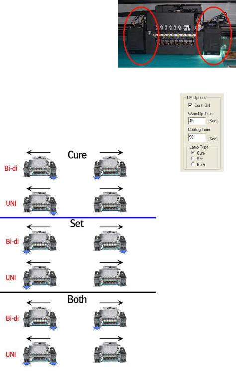
6.2. Curing setup and sequences
-Settings in software:
-Lamps continous ON (lamp stays “ON” for next print; longest lifetime)
-WarmUp Time (when turning back on the UV lamps, before ready state)
-Cooling Time (after turning off the UV lamps)
-Lamp Type: Cure (Default), Set or Both
AB]]]]]]]]]]]]]]]]]]]]]]]]]]]]]]]]]]]]]]]]]]]]]]]]]]]]]]]]]]]]]]]]]]]]]]]]]]]]]]]]]]]]]]]]]]]]]]]]]]]]]]]]]]]]]]]]]]]]]]]]]]]]]]]]]]]]]]]]]]]]]]]]]]]]]]]]]]]]]]]]]]]]]]]]]]]]]]]]]]]]]]]]]]]]]]]]]]]]]]]]]]]]]]]]]]]]]]]]]]]]]]]]]]]]15] |
8/08/2008] |
:ANAPURNA XL² |
OPERATOR MANUAL |
6.3. Uniand Bi-directional printing
-For Bi-directional printing, both UV lamps need to be used. (curing is done on the fly in both printing directions)
-For Uni-directional printing, only the right UV lamp will be used. (curing is only done when the shuttle is moving from right to left)
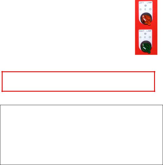
Depending on the heat-resistance/thickness of your media, you can set the UV lamp power to “Half” or “Full” power.
By default, “Full” power should be used whenever possible.
When switching ON the UV-lamps, don’t switch them from “Off” to “Full” power at once. Wait 2 seconds at “Half” power before switching them to “Full“ power. Use the same procedure when going from Full power to Off.
Note about UV-lamp life time:
The lamp life time is not only depending on the numbers of hours that a lamp generated light; Especially gas-discharged bulbs, the type that is used in general on all UV-curing systems, have a life time that is strongly influenced by the number of times that the bulb is switched ON and OFF. As a general rule, one can state that switching a bulb ON and OFF counts for about 40 minutes of head life time.
To maximize the useful life time of a bulb, one should not turn the lamps OFF after having made a print if a next job will be printed in the coming 20 to 30 minutes; For that, ‘continuous ON’ should be checked in the UV options of the setup menu, and a user only has to switch the lamps off if the machine will not be used for at least an half hour.
Due to the physics of the lamp discharge lamps, a UV-bulb can also not ignite when it is hot; For that, the UV-bulb is first cooled down for the set period after a user switched it off, before the bulb will ignite again if the user turns back on the UV-switch.
AB]]]]]]]]]]]]]]]]]]]]]]]]]]]]]]]]]]]]]]]]]]]]]]]]]]]]]]]]]]]]]]]]]]]]]]]]]]]]]]]]]]]]]]]]]]]]]]]]]]]]]]]]]]]]]]]]]]]]]]]]]]]]]]]]]]]]]]]]]]]]]]]]]]]]]]]]]]]]]]]]]]]]]]]]]]]]]]]]]]]]]]]]]]]]]]]]]]]]]]]]]]]]]]]]]]]]]]]]]]]]]]]]]]]]16] |
8/08/2008] |

:ANAPURNA XL² |
OPERATOR MANUAL |
7. Printing Table.
7.1. General information
-Woven Conveyor belt
-Transport is done by a step-motor
-On the table are 4 vacuum-zones with a variable strength. The table is evenly divided in 4 compartments. The 2 most right compartments are driven by ring blower number 1;
The 2 most left compartments are driven by ring blower number 2. The ring blower switch can be switched on in that order.
-The vacuum of each compartment can be lowered by closing the manual air valves located at the rear right side.
- The valve numbers V1 till V4 are numbered from home position (V1) till purge position (V4). The border of each compartment is indicated with a yellow sticker on the box beam.
It is very important to set the air valves depending on the media width and media type that you are using;
As a general rule, one has to close the corresponding air valve to the 30 degrees angle position (so close the valve for 2/3 of its range) if the corresponding table compartment is completely covered by the media. The valve of a partly covered compartment has to stay completely open (upright position as shown in the picture above).
Fail to do that will have as result that flexible media can get crunched up at the rear side of the vacuum table due to a too high vacuum and can cause a head crash if the ripples are coming under the heads.
Air Valve position if all 4 compartments are fully covered (full width media).
More details for specific roll-to-roll media are given at the end of this manual.
AB]]]]]]]]]]]]]]]]]]]]]]]]]]]]]]]]]]]]]]]]]]]]]]]]]]]]]]]]]]]]]]]]]]]]]]]]]]]]]]]]]]]]]]]]]]]]]]]]]]]]]]]]]]]]]]]]]]]]]]]]]]]]]]]]]]]]]]]]]]]]]]]]]]]]]]]]]]]]]]]]]]]]]]]]]]]]]]]]]]]]]]]]]]]]]]]]]]]]]]]]]]]]]]]]]]]]]]]]]]]]]]]]]]]]17] |
8/08/2008] |
 Loading...