


 Loading...
Imaging Services |
Service Manual |
|
|
|
|
Document ID: 58669036
DR 10e / DR 14e / DR 17e |
Innolux_title.cdr |
DOCUMENT CONTROL NOTE:
The controlled version of this document is available from the Agfa Medimg Library. Any printed copy of this document is uncontrolled.
Edition 1, Revision 6 |
|
|
03-2019 Printed in Germany |
Document_standard_e_template_v05 |
|
|
|
|
Agfa Company Confidential |
|
|
|
Copyright © 2019 Agfa NV |
|
Document ID: 58669036 |
Service Manual |
►Manufacturer
Agfa NV
Published by
Agfa-Gevaert HealthCare GmbH Tegernseer Landstraße 161
D - 81539 München Germany
Copyright 2019 Agfa NV
All rights reserved.
Technical modifications reserved.
Agfa and the Agfa rhombus are trademarks of Agfa NV, Belgium, or its affiliates.
All other trademarks mentioned in this document are held by Agfa NV or the respective owners and are used in an editorial fashion with no intention of infringement.
Nothing contained in this legal notice nor in any text in this document shall be construed as granting by implication, estoppel or otherwise, any license or right to use any of the trademarks, service marks, trade names or logos appearing in this document without the express prior written consent of their respective owner.
WARNING:
Improper operation or service activities may cause damage or injuries.
Read the "Generic Safety Directions" prior to attempting any operation, repair or maintenance task on the equipment. Refer to Document ID 11849633.
Strictly observe all safety directions within the "Generic Safety Directions" and on the product.
IMPORTANT:
The installation and service of the product(s) described herein is to be performed by qualified personnel who are employed by Agfa NV or one of its affiliates
or who are otherwise authorized by Agfa NV or one of its affiliates to provide such services.
DOCUMENT CONTROL NOTE:
The controlled version of this document is available from the Agfa Medimg Library. Any printed copy of this document is uncontrolled.
Edition 1, Revision 6 |
DR 10e / DR 14e / DR 17e |
Page 2 of 92 |
03-2019 |
|
Agfa Company Confidential |

Document ID: 58669036 |
Service Manual |
LIST OF CONTENTS |
|
||
0 |
ABOUT THIS MANUAL ......................................................................................................... |
6 |
|
|
0.1 |
Purpose of this document ......................................................................................................... |
6 |
|
0.2 |
Changes compared to previous revision .................................................................................. |
6 |
|
0.3 |
Referenced documents............................................................................................................. |
6 |
|
0.4 |
Explanation of notes ................................................................................................................. |
7 |
|
0.5 |
Conventions .............................................................................................................................. |
7 |
1 |
PRODUCT DESCRIPTION.................................................................................................... |
8 |
|
|
1.1 |
Intended use ............................................................................................................................. |
8 |
|
1.2 |
Components of the product....................................................................................................... |
8 |
|
1.3 |
Technical Data ........................................................................................................................ |
11 |
|
1.4 |
Connections and LEDs at the DR Detector ............................................................................ |
11 |
|
1.5 |
Serial number label and type label ......................................................................................... |
12 |
|
1.6 |
Software and hardware overview............................................................................................ |
14 |
|
1.7 |
Connection modes .................................................................................................................. |
15 |
|
1.8 |
Exposure modes ..................................................................................................................... |
16 |
|
1.9 |
Supported DR systems ........................................................................................................... |
16 |
|
1.10 |
Default and supported IP addresses....................................................................................... |
17 |
|
1.10.1 |
Restrictions, specific for DR 10e, DR 14e, DR 17e network setup......................................... |
18 |
|
1.10.2 |
Changing the IP address as of IRI 3.0.................................................................................... |
19 |
|
1.11 |
Detector sharing...................................................................................................................... |
21 |
|
1.12 |
Panel sleep mode ................................................................................................................... |
23 |
|
1.13 |
Recovery of images ................................................................................................................ |
23 |
|
1.14 |
Powerbox connection.............................................................................................................. |
24 |
|
1.14.1 |
Powerbox technical data......................................................................................................... |
25 |
|
1.15 |
EPS variant of the DR 14e...................................................................................................... |
27 |
2 |
SAFETY DIRECTIONS........................................................................................................ |
29 |
|
|
2.1 |
Safety notes for service activities............................................................................................ |
29 |
|
2.2 |
Labels...................................................................................................................................... |
29 |
3 |
PRE-INSTALLATION........................................................................................................... |
29 |
|
|
3.1 |
Items to be organized locally before installation ..................................................................... |
29 |
4 |
INSTALLATION AND CONFIGURATION ............................................................................ |
30 |
|
|
4.1 |
Installation overview................................................................................................................ |
30 |
|
4.1.1 |
Installation steps ..................................................................................................................... |
30 |
|
4.1.2 |
Required software................................................................................................................... |
32 |
DOCUMENT CONTROL NOTE:
The controlled version of this document is available from the Agfa Medimg Library. Any printed copy of this document is uncontrolled.
Edition 1, Revision 6 |
DR 10e / DR 14e / DR 17e |
Page 3 of 92 |
03-2019 |
|
Agfa Company Confidential |

Document ID: 58669036 |
Service Manual |
|
4.1.3 |
Required hardware ................................................................................................................. |
32 |
|
4.1.4 |
Required time for the installation ............................................................................................ |
32 |
|
4.1.5 |
Required documents............................................................................................................... |
33 |
|
4.2 |
Preparation.............................................................................................................................. |
33 |
|
4.2.1 |
Checking shipment completeness .......................................................................................... |
33 |
|
4.3 |
Hardware installation .............................................................................................................. |
33 |
|
4.3.1 |
Charging the battery ............................................................................................................... |
33 |
|
4.3.2 |
Installing the network interface in NX...................................................................................... |
33 |
|
4.3.3 |
Performing cable connections................................................................................................. |
34 |
|
4.4 |
Software Installation................................................................................................................ |
36 |
|
4.4.1 |
Updating NX software with DR 10e / DR 14e / DR 17e driver software (IRI component) ...... |
36 |
|
4.4.2 |
Installing network interface card driver(s) ............................................................................... |
37 |
|
4.4.3 |
Configuring the IP addresses for the network connections .................................................... |
38 |
|
4.4.4 |
Disabling sleep mode in power options .................................................................................. |
39 |
|
4.4.5 |
Configuring the access point................................................................................................... |
40 |
|
4.4.6 |
Configuring the DR Detector using the IRI Panel Installation Tool......................................... |
40 |
|
4.5 |
Configuration........................................................................................................................... |
50 |
|
4.5.1 |
Performing X-ray device configuration.................................................................................... |
50 |
|
4.5.2 |
Performing detector settings ................................................................................................... |
53 |
|
4.5.3 |
Activating the configuration..................................................................................................... |
57 |
|
4.5.4 |
Creating an administration user account on NX for detector calibration ................................ |
58 |
|
4.6 |
Installation verification............................................................................................................. |
58 |
|
4.7 |
Calibrating the DR Detector .................................................................................................... |
59 |
|
4.8 |
Performing the Acceptance Test Procedure........................................................................... |
59 |
|
4.9 |
In case of an EPS detector: Setup up EPS codemeter dongle .............................................. |
59 |
|
4.10 |
Customer training.................................................................................................................... |
60 |
|
4.11 |
Adding the detector to the serial number tracking document ................................................. |
62 |
|
4.12 |
Appendix: Dual Plus / Dual Minus Bandwidth parameter ....................................................... |
63 |
5 |
CALIBRATION..................................................................................................................... |
65 |
|
|
5.1 |
Detector calibration ................................................................................................................. |
65 |
|
5.1.1 |
Warming up the detector......................................................................................................... |
66 |
|
5.1.2 |
Preparing detector calibration ................................................................................................. |
66 |
|
5.1.3 |
Exposing the flat fields ............................................................................................................ |
67 |
|
5.1.4 |
Solving errors during detector calibration ............................................................................... |
67 |
|
5.1.5 |
Verifying the calibration........................................................................................................... |
68 |
DOCUMENT CONTROL NOTE:
The controlled version of this document is available from the Agfa Medimg Library. Any printed copy of this document is uncontrolled.
Edition 1, Revision 6 |
DR 10e / DR 14e / DR 17e |
Page 4 of 92 |
03-2019 |
|
Agfa Company Confidential |

Document ID: 58669036 |
Service Manual |
6 |
ACCEPTANCE TEST .......................................................................................................... |
68 |
|
7 |
TROUBLESHOOTING......................................................................................................... |
69 |
|
|
7.1 |
List of symptoms and solutions............................................................................................... |
69 |
|
7.1.1 |
Image quality related symptoms ............................................................................................. |
69 |
|
7.1.2 |
General DR Detector problems............................................................................................... |
70 |
|
7.1.3 |
IRI Panel Installation Tool issues............................................................................................ |
71 |
|
7.2 |
Logfiles for Troubleshooting.................................................................................................... |
76 |
|
7.2.1 |
Detector Shock counters......................................................................................................... |
76 |
|
7.3 |
Error Codes............................................................................................................................. |
77 |
8 |
REPAIR |
............................................................................................................................... |
80 |
|
8.1 |
DR Detector Repair Process................................................................................................... |
80 |
|
8.2 |
Replacing a DR 10e, DR 14e or DR 17e DR Detector ........................................................... |
80 |
9 |
MAINTENANCE................................................................................................................... |
80 |
|
10 |
RELEASE INFORMATION .................................................................................................. |
81 |
|
|
10.1 |
Software release IRI 1.0 ......................................................................................................... |
81 |
|
10.2 |
Software release IRI 1.1 ......................................................................................................... |
81 |
|
10.3 |
Software release IRI 2.0 ......................................................................................................... |
81 |
|
10.4 |
Software release IRI 2.1 ......................................................................................................... |
82 |
|
10.5 |
Software release IRI 3.0 ......................................................................................................... |
82 |
11 |
UPGRADE PROCEDURE ................................................................................................... |
83 |
|
|
11.1 |
IRI upgrade instructions .......................................................................................................... |
83 |
|
11.1.1 |
Additional step for software updates from IRI < 2.0................................................................ |
83 |
|
11.2 |
Detector firmware update........................................................................................................ |
84 |
|
11.2.1 |
Creating a flatfield image for visual inspection ....................................................................... |
84 |
|
11.2.2 |
Firmware update ..................................................................................................................... |
85 |
|
11.2.3 |
Verification .............................................................................................................................. |
88 |
12 |
SPARE PARTS.................................................................................................................... |
88 |
|
13 |
WIRING DIAGRAM.............................................................................................................. |
89 |
|
|
13.1 |
DX-D Retrofit - Instant DR (self-triggering) – 2 x wireless ...................................................... |
89 |
|
13.2 |
DX-D Retrofit - Instant DR (self-triggering) – 1 x wireless and 1 x wired................................ |
90 |
|
13.3 |
DX-D Retrofit - Instant DR (self-triggering) – 2 x wired........................................................... |
91 |
|
13.4 |
DX-D Retrofit – DR system with Generator control – 2 x wireless ......................................... |
92 |
DOCUMENT CONTROL NOTE:
The controlled version of this document is available from the Agfa Medimg Library. Any printed copy of this document is uncontrolled.
Edition 1, Revision 6 |
DR 10e / DR 14e / DR 17e |
Page 5 of 92 |
03-2019 |
|
Agfa Company Confidential |

Document ID: 58669036 |
Service Manual |
0 About this manual
0.1Purpose of this document
This document contains all information that service engineers need for installation as well as for corrective and preventive maintenance of the DR 10e / DR 14e / DR 17e. It does not contain:
•Specific service information for other target readers, e.g. Clinical Application Specialists or Service Managers
•Service Bulletins
0.2Changes compared to previous revision
•Corrected information for user training with respect to clicking another thumbnail short after exposure. Refer to section 4.10.
•Added EPS detector variant in section 1.15 and section 4.
•Adapted detector IP address setup in sections 1.10., 4.4.6. and 13.
•Added table with information about Dual Plus and Dual Minus bandwidth parameter. Refer to section 4.12.
•Removed information in section 1.10.1, that the network interface card cannot be used for other devices simultaneously (e.g. DR 600 Positioner or DR 14s detector).
•Added troubleshooting an unknown IP address using a Jig connector. Refer to section 7.1.3.3.
•Added IRI 3.0 in section 10.5.
•Added IRI upgrade instructions in section 11.1.
0.3Referenced documents
Document |
Reference |
Generic Safety Directions |
Document ID 11849633 |
|
|
Refer to the DR wireless |
Document ID 58221971 |
networking manual |
|
DR 10e / DR 14e / DR 17e User |
Refer to the Agfa Medimg Library |
Manual 0370 |
|
DX-D DR Detector Calibration Key |
Refer to the Agfa Medimg Library |
User Manual |
|
System specific User Manual |
Refer to the Agfa Medimg Library |
|
|
DOCUMENT CONTROL NOTE:
The controlled version of this document is available from the Agfa Medimg Library. Any printed copy of this document is uncontrolled.
Edition 1, Revision 6 |
DR 10e / DR 14e / DR 17e |
Page 6 of 92 |
03-2019 |
|
Agfa Company Confidential |
Document ID: 58669036 |
Service Manual |
0.4Explanation of notes
Safety-relevant Notes
Icon |
Signal Word |
Situation |
|
|
CAUTION: |
Hazardous situation which, if not avoided, can lead to a minor |
|
|
|
injury to a user, engineer, patient or any other person. |
|
|
WARNING: |
Hazardous situation which, if not avoided, can lead to a potential |
|
|
|
serious injury to a user, engineer, patient or any other person. |
|
|
DANGER: |
Direct, immediate danger: If not avoided, it can lead to a serious |
|
|
|
injury to a user, engineer, patient or any other person |
|
|
- |
Instruction to avoid damage to equipment and/or environmental |
|
|
|
pollution. |
|
|
- |
Prohibition to avoid damage to equipment and/or environmental |
|
|
|
pollution. |
|
None-Safety-relevant Notes |
|
||
Icon |
Name |
Type of Information |
|
|
IMPORTANT: |
Highlights very important actions which have to be carried out to |
|
|
|
prevent malfunction. |
|
|
NOTE: |
• |
Indicates advice to facilitate the following step or action |
|
|
|
without having a direct influence on the step or action. |
|
|
• |
Highlights unusual points. |
|
|
• |
Indicates background information. |
|
|
• |
Can be used to explain or highlight displays of the |
|
|
|
graphical user interface. |
0.5Conventions
Highlighting of tasks
|
Task number |
Task Description |
|
Remark |
|
|
|
(1) |
|
Connect the cable. |
|
Examples for working steps to be performed in |
|
|
(2) |
|
Switch the machine on. |
the listed sequence. |
|
|
|
|
|
|
|||
|
|
|
|
|||
|
Highlighting of buttons, functions and names within a task |
|
||||
|
(1) |
Press F9 or double-click the |
The bold typeface is used for menu topics, keyboard |
|
||
|
|
Refresh button. |
keys, icons, device buttons, commands etc. |
|
||
|
(2) |
If the Install client or |
The Courier New bold typeface is used for system |
|
||
|
|
server? prompt appears, |
messages and prompts. |
|
||
|
|
type server. |
|
|
|
|
DOCUMENT CONTROL NOTE:
The controlled version of this document is available from the Agfa Medimg Library. Any printed copy of this document is uncontrolled.
Edition 1, Revision 6 |
DR 10e / DR 14e / DR 17e |
Page 7 of 92 |
03-2019 |
|
Agfa Company Confidential |
Document ID: 58669036 |
Service Manual |
1 Product description
1.1Intended use
The intended use statement is listed in the User Manuals of the DR 10e / DR 14e / DR 17e DR Detector.
1.2Components of the product
Following components are required to integrate the DR Detector into a DR system:
For how to obtain the different components as sales items refer to the DR system specific sales information. Most parts are also available as spare parts.
Refer to section 12.
# |
Component / Purpose |
Picture |
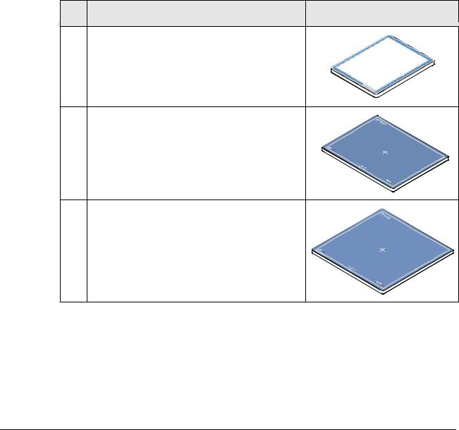
1A |
DR 10e C |
|
|
Available as CSI (Cesium iodide) |
|
|
wireless DR Detector. |
|
|
Captures X-ray images. |
|
|
Dimension: 268 x 328 x 15 mm |
|
1B |
DR 14e C / G |
|
|
Available as CSI (Cesium iodide) or GOS |
|
|
wireless DR Detector. |
|
|
Captures X-ray images. |
|
|
Dimension: 384 x 460 x 15 mm |
|
|
|
innolux_DR14e.cdr |
1C |
DR 17e C / G |
|
|
Available as CSI (Cesium iodide) or GOS |
|
|
(Gadolinium oxysulfide) wireless DR |
|
|
Detector. |
|
|
Captures X-ray images. |
|
|
Dimension: 460 x 460 x 15 mm |
|
|
|
innolux_DR17e.cdr |
DOCUMENT CONTROL NOTE:
The controlled version of this document is available from the Agfa Medimg Library. Any printed copy of this document is uncontrolled.
Edition 1, Revision 6 |
DR 10e / DR 14e / DR 17e |
Page 8 of 92 |
03-2019 |
|
Agfa Company Confidential |
Document ID: 58669036 |
|
Service Manual |
|||||||
|
|
|
|
|
|
|
|
|
|
|
|
# |
|
|
Component / Purpose |
|
|
Picture |
|
|
|
|
|
|
|
|
|||
|
|
|
|
|
|
|
|
|
|
|
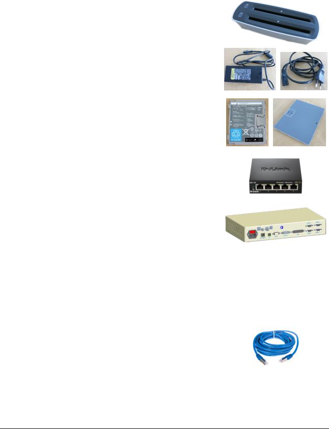
2 |
|
|
Battery charger |
|
|
|
||
|
|
|
|
|
Provides power to two batteries for |
|
|
|
|
|
|
|
|
|
simultaneous recharging. |
|
|
|
|
|
|
|
|
|
Informs the user about battery status. |
|
|
|
|
|
|
|
|
Includes an AC/DC adapter |
|
|
|
||
|
|
|
|
Input voltage 100 to 240 V AC |
|
|
|
||
|
|
|
|
|
Output voltage / current 16 V DC, 6.5 A |
|
|
|
|
|
|
|
|
|
Input connector: C8 |
|
|
|
|
|
|
|
|
|
Output connector D-Sub 9 female |
|
|
|
|
|
|
|
|
|
|
|
|
||
|
3 |
|
|
Additional battery |
|
|
|
||
|
|
|
|
|
Can be used for DR 10e, DR 14e or DR 17e. |
|
|
|
|
|
|
|
|
|
|
|
|||
|
|
4 |
D-Link network switch DGS-105 (optional) |
|
|
|
|||
|
|
|
|
|
5 port unmanaged switch |
|
|
|
|
|
|
|
|
|
Connects the different network devices. |
|
|
|
|
|
|
|
|
|
Also supported: |
|
|
|
|
|
|
|
|
|
8 port switch DGS-108 |
|
|
|
|
|
|
|
|
|
|
|
|||
|
|
5 |
DR Generator Sync Box (optional) |
|
|
|
|||
|
|
|
|
|
Interface between Generator and NX for |
|
|
|
|
|
|
|
|
|
exposure sync signals. |
|
|
|
|
|
|
|
|
|
DR Detector control (Panel 1 to Panel 4) is |
|
|
|
|
|
|
|
|
not connected. VARCAN interface(s) not |
|
|
|
||
|
|
|
|
|
used. |
|
|
|
|
|
|
|
|
|
Not required for Instant DR (self-triggering), |
|
|
|
|
|
|
|
|
|
DX-D 100 and DX-D 300. For details refer to |
|
|
|
|
|
|
|
|
|
section 13, Wiring diagrams. |
|
|
|
|
|
|
|
|
|
|
|
|||
|
6 |
|
|
Access point (optional) |
|
Refer to the DR wireless |
|||
|
|
|
|
|
|
|
|
networking manual, Document |
|
|
|
|
|
|
|
|
|
ID 58221971 |
|
|
|
|
|
|
|
|
|||
|
|
7 |
Standard, straight network cable CAT 5 (or |
|
|
|
|||
|
|
|
|
|
CAT 6) |
|
|
|
|
|
|
|
|
|
Up to three network cables are required, |
|
|
|
|
|
|
|
|
|
depending on the DR system. |
|
|
|
|
|
|
|
|
|
For details refer to section 13, Wiring |
|
|
|
|
|
|
|
|
|
diagrams. |
|
|
|
|
|
|
|
|
|
|
|
|
|
|
DOCUMENT CONTROL NOTE:
The controlled version of this document is available from the Agfa Medimg Library. Any printed copy of this document is uncontrolled.
Edition 1, Revision 6 |
DR 10e / DR 14e / DR 17e |
Page 9 of 92 |
03-2019 |
|
Agfa Company Confidential |
Document ID: 58669036 |
Service Manual |
# |
Component / Purpose |
Picture |
8PCIe Intel Gigabit CT desktop adapter
Image interface for the DR Detector. Can be used for up to four DR detectors.
Not required for notebooks.
9USB to Ethernet adapter (optional)
Network interface to the hospital network for notebooks. In this case the on-board network interface is used for connection to the detector.
10 Powerbox (optional) |
|
Required for wired connection. |
|
Cable length: 10 m |
|
Provides power for the detector (battery can |
|
remain inserted). For more details refer to |
|
section 1.14. |
Rear view |
259 mm (width) x 205 mm (depth) x 70 mm |
Ethernet |
(height). |
|
Weight 3.2 kg |
Detector |
Power |
11Registration cable
Connects the detector to the network card or network switch. Does not provide power. Length 80 cm.
•Required by the FSE during installation to write system specific data to the detector.
•Required by the user to write wireless networking data for detector sharing. May not be used for image transfer.
12Detector specific CD
Comes with each DR 10e, DR 14e and DR 17e DR Detector.
Has a serial number label attached on the cover.
DOCUMENT CONTROL NOTE:
The controlled version of this document is available from the Agfa Medimg Library. Any printed copy of this document is uncontrolled.
Edition 1, Revision 6 |
DR 10e / DR 14e / DR 17e |
Page 10 of 92 |
03-2019 |
|
Agfa Company Confidential |
Document ID: 58669036 |
Service Manual |
1.3Technical Data
The technical data are listed in DR 10e, DR 14e, DR 17e User Manual on the Agfa Medimg Library.
1.4Connections and LEDs at the DR Detector
|
Battery status |
|
READY |
|
ON: Exposure possible |
|
Blinking 1/sec: Exposure* |
|
OFF: Not ready |
Green |
POWER |
|
ON: Power ON |
|
Blinking 1/sec: Error occured* |
|
OFF: Power OFF |
Blue |
ERROR |
Orange |
Blinking 1/sec: Error occurred* |
White |
OFF: Normal |
|
LINK |
|
ON: Connected |
|
OFF: No communication |
|
* If green, blue and red LED light up: |
|
Defective battery is inserted. |
innolux_009.cdr
Cable connector
Figure 1
NOTE:
The detector does not have a power switch.
Reboot is done by taking out the battery for a few seconds.
DOCUMENT CONTROL NOTE:
The controlled version of this document is available from the Agfa Medimg Library. Any printed copy of this document is uncontrolled.
Edition 1, Revision 6 |
DR 10e / DR 14e / DR 17e |
Page 11 of 92 |
03-2019 |
|
Agfa Company Confidential |
Document ID: 58669036 |
Service Manual |
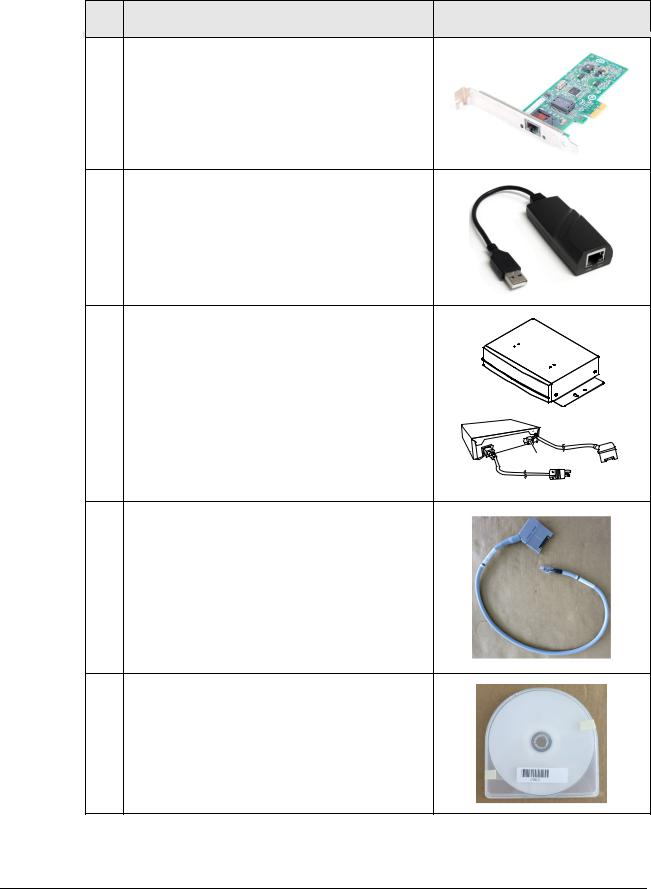
1.5Serial number label and type label
The following figure shows the location of the serial number label.
Serial number (Example)
Battery removed
Located below battery
Type Label
innolux_010B.cdr
Figure 2
The figure next page shows the type labels.
DOCUMENT CONTROL NOTE:
The controlled version of this document is available from the Agfa Medimg Library. Any printed copy of this document is uncontrolled.
Edition 1, Revision 6 |
DR 10e / DR 14e / DR 17e |
Page 12 of 92 |
03-2019 |
|
Agfa Company Confidential |

Document ID: 58669036 |
Service Manual |
0 |
innolux_010A.cdr |
Figure 3
DOCUMENT CONTROL NOTE:
The controlled version of this document is available from the Agfa Medimg Library. Any printed copy of this document is uncontrolled.
Edition 1, Revision 6 |
DR 10e / DR 14e / DR 17e |
Page 13 of 92 |
03-2019 |
|
Agfa Company Confidential |
Document ID: 58669036 |
Service Manual |
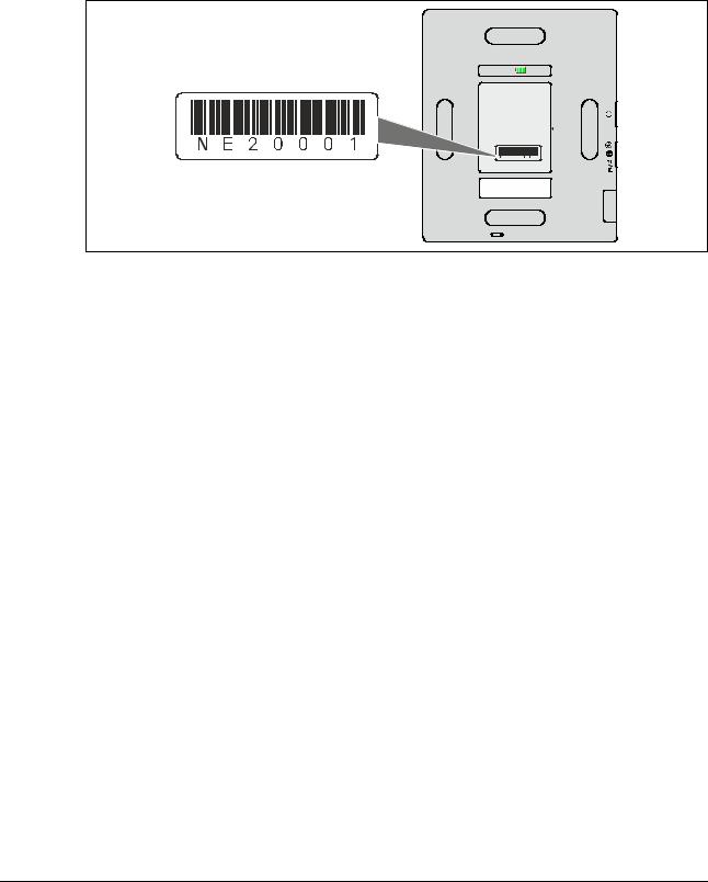
1.6Software and hardware overview
Instant DR (self-triggering)
NX Workstation
NX |
SPM or |
Control (optional) |
|
||
|
SDL or |
|
|
|
|
XRDI |
SMS |
|
|
Image & Control |
|
|
IRI |
|
|
|
Generator
 DR 10e / DR 14e / DR 17e
DR systems with sync via DR Generator Sync Box |
|||
NX Workstation |
Control |
DR Generator |
|
NX |
RFBC* |
||
|
|
|
Sync Box |
|
SPM or |
Control |
Control |
|
Generator |
||
XRDI |
SDL or |
|
|
SMS |
|
|
|
|
IRI |
Image & Control |
DR 10e / DR 14e / DR 17e |
|
|
||
*RFBC not installed in case of USB connection between Generator Sync Box and NX.
DX-D 100 / DX-D 300 / DR 100e
NX Workstation
NX |
|
|
THX (DR 100e) or |
Control |
|
SSC (DX-D 100/300) |
||
|
||
XRDI |
Image & |
|
|
||
IRI |
Control |
|
|
Generator
 DR 10e / DR 14e / DR 17e
RFBC = Retrofit Box Control
IRI = Innolux Radiographic Interface
XRDI = X-ray device interface
SPM = Spellman Generator Component
SDL = Sedecal Generator Component
SMS = Siemens Generator Component
SSC = Sedecal Soft Console
THX = Technix Generator Component
innolux_017.cdr
Figure 4
DOCUMENT CONTROL NOTE:
The controlled version of this document is available from the Agfa Medimg Library. Any printed copy of this document is uncontrolled.
Edition 1, Revision 6 |
DR 10e / DR 14e / DR 17e |
Page 14 of 92 |
03-2019 |
|
Agfa Company Confidential |

Document ID: 58669036 |
Service Manual |
||
Software Components |
|
||
|
|
|
|
|
Component |
Comment |
|
|
XRDI |
X-ray device interface. Generic software component, which |
|
|
|
interfaces between the NX application software and other, system |
|
|
|
specific software interfaces. |
|
|
RFBC |
Optional. Retrofit Box Control. Software interface for the control of |
|
|
|
the DR Generator Sync Box via Ethernet. |
|
|
SPM |
Optional. Spellman Generator Component. Software interface for the |
|
|
|
control of the Spellman Generator. |
|
|
SDL |
Optional. Sedecal Generator Component. Software interface for the |
|
|
|
control of the Sedecal Generator. |
|
|
SMS |
Optional. Siemens Generator Component. Software interface for the |
|
|
|
control of the Siemens Generator. |
|
|
SSC |
Optional. Sedecal Soft Console. Software interface for the control of |
|
|
|
the Soft console on NX (right part of the GUI) and for control of the |
|
|
|
Sedecal Generator. |
|
|
THX |
Technix Generator Component. Software interface for the control of |
|
|
|
the Technix (DR 100e) Generator. |
|
|
IRI |
Innolux Radiographic Interface. Software interface for image and |
|
|
|
control data of the DR 10e / DR 14e / DR 17e DR Detector. |
|
1.7Connection modes
Image transfer between detector and NX can be wireless or wired. For wired connection the Power Box is required. A mix of wireless and wired connection in a system is possible.
For example system wiring diagrams refer to section 13, Wiring diagram.
DOCUMENT CONTROL NOTE:
The controlled version of this document is available from the Agfa Medimg Library. Any printed copy of this document is uncontrolled.
Edition 1, Revision 6 |
DR 10e / DR 14e / DR 17e |
Page 15 of 92 |
03-2019 |
|
Agfa Company Confidential |

Document ID: 58669036 |
Service Manual |
1.8Exposure modes
The detector can be configured on NX for exposure control by the Generator or autotrigger mode. In auto-trigger mode the detector senses the X-ray beam, what is the trigger to start image capture.
Generator control can be:
•Integrated, this means the detector gets the signal to start image capture by the Generator. This is called router mode on the DR Generator Sync Box. In this mode the Generator Sync Box is just routing the exposure signals through.
•Non-integrated, this means the DR Generator Sync Box sends the exposure signal to the Generator. After the configured prepdelay, the detector starts image capture. This is called retrofit mode on the DR Generator Sync Box.
1.9Supported DR systems
The DR 14e / DR 17e is initially supported in a limited number of Agfa DR systems, for example DR 100e, DX-D Retrofit and DR 400.
For release status refer to the DR system specific Service Manual.
The released systems can also be looked up in the simplified ELMS DR Sub product Interoperability Matrix, Document ID 35878296. This document lists these systems, where the IRI detector software component can be installed.
DOCUMENT CONTROL NOTE:
The controlled version of this document is available from the Agfa Medimg Library. Any printed copy of this document is uncontrolled.
Edition 1, Revision 6 |
DR 10e / DR 14e / DR 17e |
Page 16 of 92 |
03-2019 |
|
Agfa Company Confidential |

Document ID: 58669036 |
Service Manual |
1.10Default and supported IP addresses
The following table lists the default IP address for a component from stock.
For recommended IP addresses in the system refer also to the wiring diagrams in section 13.
|
Factory IP |
Supported IP address |
Supported IP address |
|
address |
up to IRI 2.1 |
as of IRI 3.0 |
DR 10e / |
192.168.0.30 |
Automatically assigned |
Initial IP address |
DR 14e / |
|
to 192.168.0.ZZZ with |
assignment like for |
DR 17e |
|
ZZZ = 31 to 255 except |
IRI ≤ 2.1. See NOTE |
|
|
40. |
below. Subnet YYY of |
|
|
See NOTE below. |
IP address |
|
|
|
192.168.YYY.ZZZ can |
|
|
|
be adapted. See 0. |
Network |
Not defined |
192.168.0.10 |
Initially 192.168.YYY.10 |
interface |
|
Adapter name: Eth1 |
with YYY = 0. |
in NX |
|
Mandatory setting. |
Adapter name: Eth1 |
|
|
See 1.10.1. |
Mandatory setting. |
|
|
|
See 1.10.1. |
DR |
192.168.100.30 |
192.168.0.ZZ |
Initially 192.168.YYY.ZZ |
Generator |
|
with ZZ < 30 |
with YYY = 0 |
Sync Box |
|
Recommended |
and ZZ < 30 |
|
|
192.168.0.15 |
Recommended |
|
|
|
192.168.0.15 |
Access |
Depends on |
192.168.0.ZZ |
192.168.YYY.ZZ |
point |
access point |
with ZZ < 30 |
with YYY = 0 |
|
model |
Recommended: |
and ZZ < 30 |
|
|
192.168.0.20 |
Recommended: |
|
|
|
192.168.0.20 |
NOTE 1:
The IRI Panel Installation Tool assigns the IP address to the detector automatically based on the following criteria:
•IP address range 192.168.0.31 to 192.168.0.255 except 192.168.0.40.
•IP address is calculated based on the detector serial number: When removing the detector from the IRI Panel Installation Tool and configuring it again, the IP address will be the same.
•If the calculated IP address is already assigned to another DR 10e, DR 14e or DR 17e, automatically another IP address in the supported range is assigned.
DOCUMENT CONTROL NOTE:
The controlled version of this document is available from the Agfa Medimg Library. Any printed copy of this document is uncontrolled.
Edition 1, Revision 6 |
DR 10e / DR 14e / DR 17e |
Page 17 of 92 |
03-2019 |
|
Agfa Company Confidential |
Document ID: 58669036 |
Service Manual |
NOTE 2:
As of NX 3.0.8950 the software looks for the network adapter name "Local Area Connection XYZ" (for example “Local Area Connection 2”) to determine the MAC Address of the network adapter on the PC's motherboard. In case of a different name the licensing service fails to retrieve the MAC address of that adapter.
For the DR 10e, DR 14e and DR 17e it is required to rename the network adapter to “Eth1”. To prevent a failing licensing service, the IRI software also installs a new licensing component on NX, which does not have this restriction anymore.
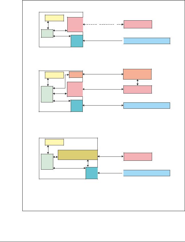
1.10.1Restrictions, specific for DR 10e, DR 14e, DR 17e network setup
For the network interface on NX the following restrictions apply:
•The name of the network interface must be Eth1. This name is case sensitive.
•The IP address must be
192.168.YYY.10
YYY = 0 for IRI ≤ 2.1
YYY = 0 to 255 for IRI ≥ 3.0
• No second IP address must be |
Figure 5 |
|
|
configured. |
|
The IRI Panel Installation Tool checks |
|
these requirements at the end of the |
|
setup. |
|
NOTE: |
|
General rule for NIC (Network Interface Card) IP setup: |
|
Each NIC on NX must be in its own subnet. |
|
Example: If one NIC is set to 192.168.0.10, the other must be for example on 192.168.100.10.
DOCUMENT CONTROL NOTE:
The controlled version of this document is available from the Agfa Medimg Library. Any printed copy of this document is uncontrolled.
Edition 1, Revision 6 |
DR 10e / DR 14e / DR 17e |
Page 18 of 92 |
03-2019 |
|
Agfa Company Confidential |
Document ID: 58669036 |
Service Manual |
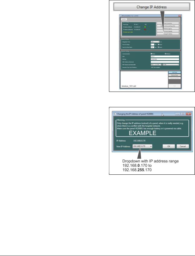
1.10.2Changing the IP address as of IRI 3.0
As of software IRI 3.0 it is possible to adjust the IP address 192.168.YYY.ZZZ.
•YYY can be changed in the range of 0 to 255 (new with IRI 3.0).
•ZZZ is automatically assigned by the IRI panel installation tool (assignment mechanism independent of IRI software).
This way it is possible to change the default subnet 192.168.0 to – for example – 192.168.1, if the subnet 192.168.0 is already used by the hospital.
Changing the IP address is done in the
IRI panel installation tool via dropdown.
Figure 6
Figure 7
DOCUMENT CONTROL NOTE:
The controlled version of this document is available from the Agfa Medimg Library. Any printed copy of this document is uncontrolled.
Edition 1, Revision 6 |
DR 10e / DR 14e / DR 17e |
Page 19 of 92 |
03-2019 |
|
Agfa Company Confidential |
Document ID: 58669036 |
Service Manual |
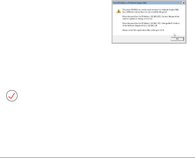
Basic rules for IP address setup:
# |
Rule |
Example |
1 |
Only change the subnet if |
192.168.0 is occupied by the hospital |
|
needed. |
network. Change subnet to 192.168.1. |
2 |
When changing the IP address |
Either use a sticker or write the changed IP |
|
setup, label the detector with |
address (for example 192.168.1.170) on the |
|
the changed IP address. |
detector cover, below the battery. |
3 |
Before starting the IRI panel |
Subnet is changed to 192.168.1. |
|
installation tool to install a new |
To install a new detector, change IP |
|
detector, adapt the IP address |
address of NIC temporarily back to default |
|
of the NIC to the detector |
192.168.0. |
|
subnet. |
|
4 |
When changing the NIC IP |
IP address is changed from 192.168.0.170 |
|
address, restart the IRI panel |
to 192.168.1.170. |
|
installation tool. Reason: IP |
NIC IP address is changed to 192.168.1.10. |
|
address is only checked at |
Now the IRI panel installation tool needs to |
|
startup of the tool. |
|
|
be restarted to allow again connection to the |
|
|
|
|
|
|
detector. |
|
|
|
5 |
When adding a second |
|
|
detector to a system, where |
|
|
the default IP address has |
|
|
been changed, ignore |
|
|
messages about differences in |
|
|
the subnet. These messages |
|
|
will be gone when the network |
|
|
interface IP address is adapted |
|
|
again. |
Figure 8 |
|
|
|
|
|
|
6 |
Detector sharing when the |
Subnet for detector is 192.168.100.ZZZ. |
|
default IP address has been |
When sharing the detector, change the |
|
changed: The subnets for the |
network interface on the other NX to |
|
detector must be the same on |
192.168.100.ZZZ before starting the IRI |
|
both NX. |
Panel Installation Tool. |
|
|
|
NOTE:
If the IP address of a DR 10e, DR 14e, DR 17e is unknown, there are three possibilities to find it back:
•Possibility 1: Connect the registration cable to the detector. Start the IRI panel installation tool: The IP address of the detector is shown.
•Possibility 2: Look up the IP address of the NIC. This shows the correct subnet.
•Possibility 3: Reset to default by using a Jig connector. For details refer to section 7.1.3.3.
DOCUMENT CONTROL NOTE:
The controlled version of this document is available from the Agfa Medimg Library. Any printed copy of this document is uncontrolled.
Edition 1, Revision 6 |
DR 10e / DR 14e / DR 17e |
Page 20 of 92 |
03-2019 |
|
Agfa Company Confidential |
Document ID: 58669036 |
Service Manual |
1.11Detector sharing
Detector sharing means: Using a DR Detector at different systems, e.g. DR 100e and DX-D Retrofit.
When changing from one system to another, the user needs to register the DR Detector at NX.
The registration workflow works as follows:
•User ensures that no active thumbnail is present for another DR 10e, DR 14e or DR 17e configured at the system (as long as a thumbnail is active, registration will not work).
•User connects the detector to the NX either via short registration cable or via Power Box.
•After some seconds the detector switch shows the wired icon 

 for this detector.
•In case of wireless detector usage: Disconnect the registration cable.
•When changing from wireless to wired: Reboot detector by removing battery and detector cable.
•When changing from wired to wireless: Reboot detector by removing and inserting battery.
•Detector is ready.
During registration following data are written to the DR Detector:
•Access point SSID
•Access point PSK Key
In case the DR detectors are configured for different trigger mode on the two systems (Exposync / Self Trigger Mode), a reboot of the DR Detector is required after having it registered on another NX.
IMPORTANT:
When adding a detector to a system, the calibration data on the detector are erased. As a consequence:
•First add all detectors to all systems, then perform calibration at the main NX for this detector.
•If a detector is added later on to a system (e.g. customer bought an additional Agfa DR system), detector calibration has to be redone at the main NX.
DOCUMENT CONTROL NOTE:
The controlled version of this document is available from the Agfa Medimg Library. Any printed copy of this document is uncontrolled.
Edition 1, Revision 6 |
DR 10e / DR 14e / DR 17e |
Page 21 of 92 |
03-2019 |
|
Agfa Company Confidential |

Document ID: 58669036 |
Service Manual |
Note that the procedure to register a detector differs for different detector brands:
•The DR 10e / DR 14e / DR 17e is registering automatically by connecting the registration cable or Power Box cable.
•On the DX-D 30 / DX-D 35 DR Detector the user needs to press the power switch in front of the IR data communication unit shortly to initiate registration.
•The DR 10s / DR 14s registers automatically as soon as the detector is close enough to the IR data communication unit.
•The DX-D 40 / DX-D 45 requires cable connection to the system control unit (SCU).
A video clip on the Agfa Medimg Library explains detector sharing. Refer to document ID 57923570. This video clip does not contain detector sharing for DR 10e / DR 14e / DR 17e.
DOCUMENT CONTROL NOTE:
The controlled version of this document is available from the Agfa Medimg Library. Any printed copy of this document is uncontrolled.
Edition 1, Revision 6 |
DR 10e / DR 14e / DR 17e |
Page 22 of 92 |
03-2019 |
|
Agfa Company Confidential |

Document ID: 58669036 |
Service Manual |
1.12Panel sleep mode
In the “IRI Panel Installation Tool” two parameters can be set to save battery power:
Parameter |
Description |
|
Time out sleep |
Indicates the idle time after which the panel will go to sleep. In |
|
Default: 15 min. |
sleep mode, the panel’s battery consumption is much less than |
|
Range: |
when not asleep. In sleep mode the DR Detector is only |
|
listening to messages from the NX. The detector is not |
||
15 to 99 min. |
||
operational. |
||
or Never |
||
The DR Detector wakes up again, when the user clicks a |
||
|
||
|
thumbnail on NX for this DR Detector. |
|
|
|
|
Time out shut |
Indicates the time asleep after which the panel will |
|
down |
automatically shutdown. So this timer will only start after the |
|
Default: 15 min. |
panel has been asleep for a while. For example, when both |
|
Range: |
values are on 15, then after 15 minutes idle time the DR |
|
Detector will go asleep and 15 minutes later, the DR Detector |
||
15 to 99 min. |
||
will shutdown. Any user actions in NX towards the DR Detector |
||
or Never |
||
will reset the timers. |
||
|
||
|
In this mode the blue LED of the detector is still ON, but the |
|
|
detector can only be started again by removing and re- |
|
|
inserting the battery. The battery indicator on the detector rear |
|
|
is off in this mode. |
Both timers only work if both of the following conditions are fulfilled:
•The DR Detector is in WiFi range
•NX application is running Reason: NX is the master for both timers.
The timers are also not used for following conditions:
•When a thumbnail is active for a DR 10e, DR 14e or DR 17e.
•During DR Detector calibration.
•In case of a detector related error message.
1.13Recovery of images
For image recovery in case the image could not be sent to the NX e.g. due to WiFi transmission problems, refer to the Application Note “DR image recovery on the NX Workstation”, Document ID 43993890.
DOCUMENT CONTROL NOTE:
The controlled version of this document is available from the Agfa Medimg Library. Any printed copy of this document is uncontrolled.
Edition 1, Revision 6 |
DR 10e / DR 14e / DR 17e |
Page 23 of 92 |
03-2019 |
|
Agfa Company Confidential |
Document ID: 58669036 |
Service Manual |
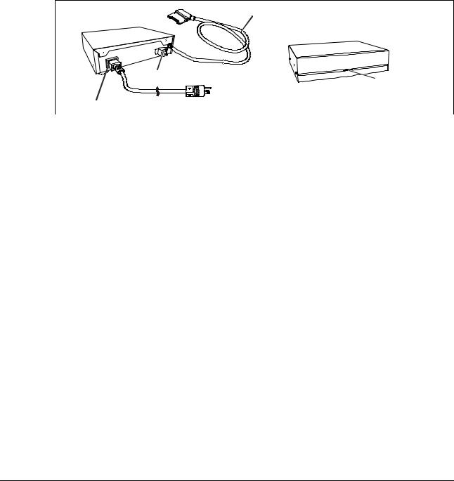
1.14Powerbox connection
The Powerbox allows a permanent or temporary cabled connection between NX and DR 10e, DR 14e or DR 17e.
This can be required for example, if in a retrofit solution the bucky design prevents a reliable wireless connection.
Functions of the Powerbox:
•Provides power for the detector.
•Provides cabled connection for image transmission.
10 m cable to detector (non-detachable on Powerbox)
Ethernet connection |
Power status LED |
|
C13 power input connector |
innolux_057.cdr |
|
|
|
Figure 9 |
It is possible to use the Powerbox for different detectors, but only one detector at a time. See also wiring examples in sections 13.2 and 13.3.
The Power Box is a simple device: It just adds power to the detector. The incoming Ethernet cable is looped through. In fact the cable has the same functionality as the registration cable, apart from the power supply.
As the Power Box gives power to the detector, a battery in the detector is not needed during operation. The battery can also be left in during operation with the Powerbox. In this case the battery is charged by the Powerbox. This might be usefull when using the detector for cabled and wireless image transmission at a system.
Due to its narrow operating temperature range (refer to section 1.14.1, Powerbox technical data), the Powerbox is not suited to be built in a cabinet without additional cooling.
DOCUMENT CONTROL NOTE:
The controlled version of this document is available from the Agfa Medimg Library. Any printed copy of this document is uncontrolled.
Edition 1, Revision 6 |
DR 10e / DR 14e / DR 17e |
Page 24 of 92 |
03-2019 |
|
Agfa Company Confidential |
Document ID: 58669036 |
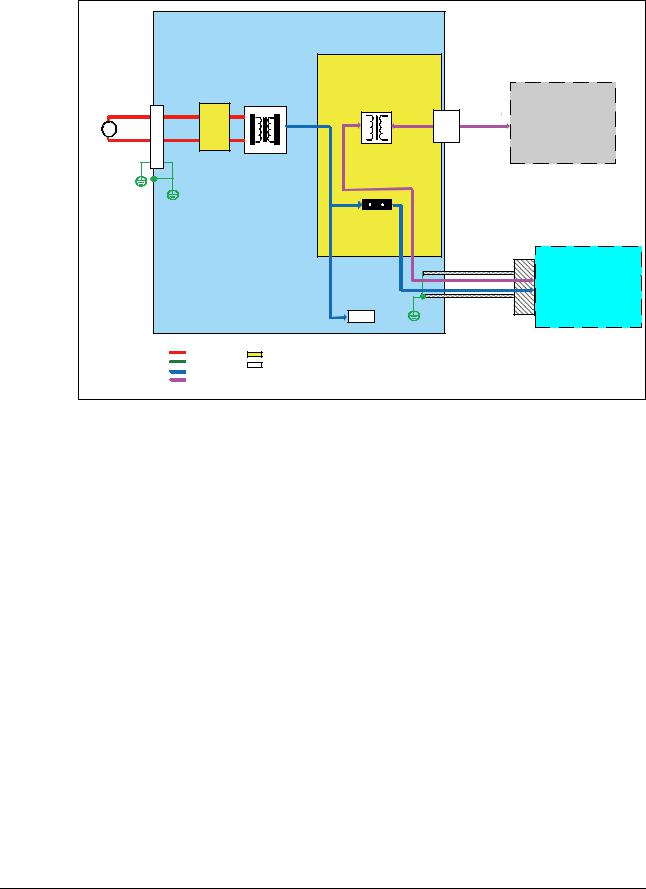
Service Manual |
|
Power Box |
|
|
|
|
|
|
|
|
|
|
MPS65A Board |
|
|
|
AC100-240V |
INLET |
Noise Filter |
Power Supply |
|
|
|
|
50-60Hz |
Pulse Transformer |
|
|
|
|||
|
|
|
|
|
|||
~ |
|
NFB |
DC12V |
Signal |
LAN |
LAN cable |
NX |
|
51A |
|
|
conne |
|
||
|
|
Board |
|
|
ctor |
|
|
|
|
|
|
Signal |
|
|
|
|
|
|
|
2A |
|
|
|
|
|
|
|
|
|
|
DR 10e / DR 14e / |
|
|
|
|
|
|
|
DR 17e |
|
|
|
|
LED |
|
|
|
|
|
AC Line |
Board |
|
|
|
|
|
|
GND Line |
Parts |
|
|
|
|
|
|
DC Line |
|
|
|
|
|
|
|
|
|
|
|
|
|
|
|
Signal |
|
|
|
|
|
|
|
|
|
innolux_021.cdr |
|
|
|
Figure 10: Powerbox block diagram
1.14.1Powerbox technical data Operating conditions
Parameter |
Value |
|
Temperature |
15°C (15% RH) to 30°C (80% RH) |
|
|
|
|
Humidity |
15% RH (15°C) to 80% RH (30°C) no dew condensation |
|
|
|
|
Atmospheric pressure |
700 hPa – 1060 hPa |
|
|
|
|
Power Supply Conditions |
|
|
Parameter |
Value |
|
Rated voltage |
100 to 240 |
VAC |
|
|
|
Input current |
2.0 to 0.84 |
A |
|
|
|
Frequency |
50 to 60 Hz |
|
|
|
|
DOCUMENT CONTROL NOTE:
The controlled version of this document is available from the Agfa Medimg Library. Any printed copy of this document is uncontrolled.
Edition 1, Revision 6 |
DR 10e / DR 14e / DR 17e |
Page 25 of 92 |
03-2019 |
|
Agfa Company Confidential |
Document ID: 58669036 |
|
|
Service Manual |
||||
|
Dimensions |
|
|
|
|
||
|
|
|
|
|
|
|
|
|
Parameter |
Value |
|||||
|
Width x depth x height |
259 mm x 205 mm x 70 mm |
|||||
|
|
|
|
|
|
|
|
|
|
|
|
|
|
|
|
|
|
|
|
|
|
|
|
259 mm
70 mm
Figure 11
205 mm
innolux_028.cdr
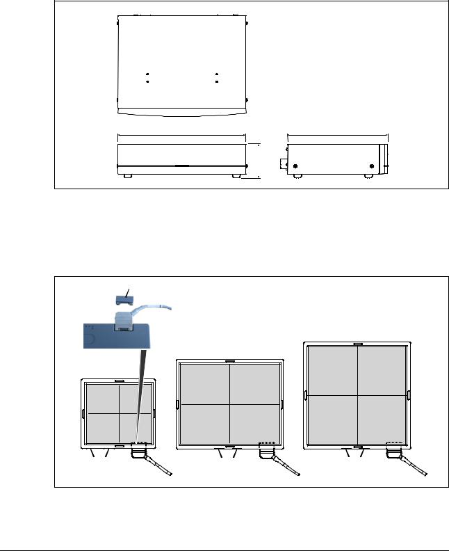
Cable connection is at the detector front side. The cable outlet direction can be to the left or to the right (default: right). The cable outlet direction can be changed by the Field Service Engineer. Refer to instructions in section 4.3.3.1.
Cover |
|
|
|
|
DR 17e |
Rear view |
DR 14e |
|
DR 10e |
|
|
Status lamps |
Status lamps |
Status lamps |
Connector |
Connector |
Connector |
innolux_029.cdr |
|
|
Figure 12
DOCUMENT CONTROL NOTE:
The controlled version of this document is available from the Agfa Medimg Library. Any printed copy of this document is uncontrolled.
Edition 1, Revision 6 |
DR 10e / DR 14e / DR 17e |
Page 26 of 92 |
03-2019 |
|
Agfa Company Confidential |
Document ID: 58669036 |
Service Manual |
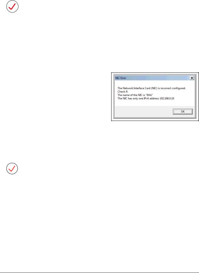
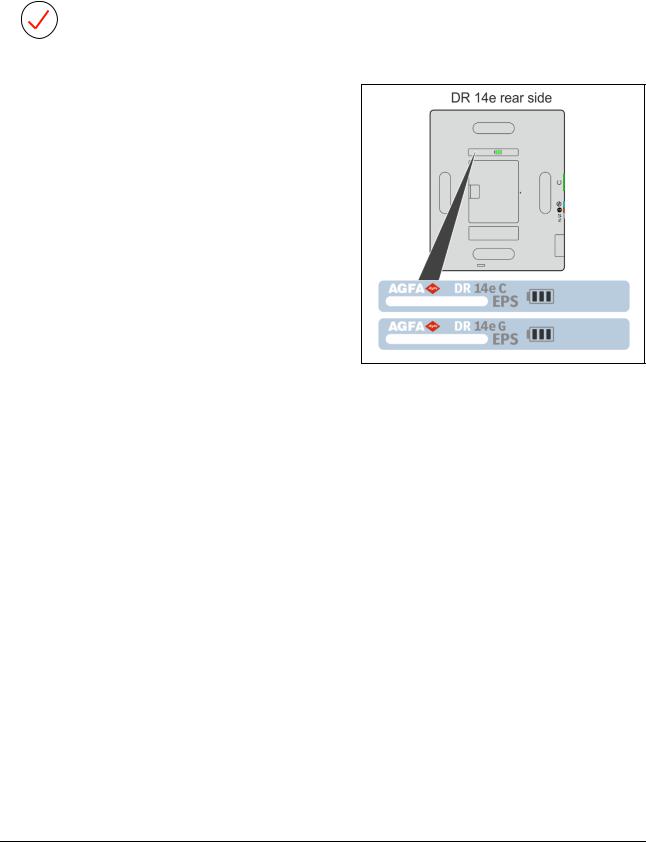
1.15EPS variant of the DR 14e
NOTE:
EPS (Easy Payment Scheme) is a business model, where the customer buys a time-limited license for the detector, which can be renewed by the customer.
The EPS variant of the DR 14e can be recognized by an EPS label in the rear of the detector.
There is no difference in installation, troubleshooting and replacement compared to a non-EPS detector.
Figure 13
Restrictions:
•EPS detector only gets ready on NX, if the NX dongle contains a valid EPS license. Typical payment scheme:
o The first 10 days after installation: Grace period, where detector also works without license.
o The first 3 months no license fee must be paid.
o After 3 months, the customer needs to renew the license monthly by a payment in the EPS customer portal.
o For details to licensing refer to the EPS for DR Detectors - Service Manual – Document ID 67216623.
•Only one EPS detector per NX.
•No mix EPS / non-EPS detector.
•Not possible to change EPS detector to a non-EPS detector by firmware update.
•Codemeter dongle required on NX. This needs to be ordered separately.
•At detector replacement, the new detector needs to be transferred to the license (described in EPS for DR Detectors - Service Manual).
DOCUMENT CONTROL NOTE:
The controlled version of this document is available from the Agfa Medimg Library. Any printed copy of this document is uncontrolled.
Edition 1, Revision 6 |
DR 10e / DR 14e / DR 17e |
Page 27 of 92 |
03-2019 |
|
Agfa Company Confidential |
Document ID: 58669036 |
Service Manual |
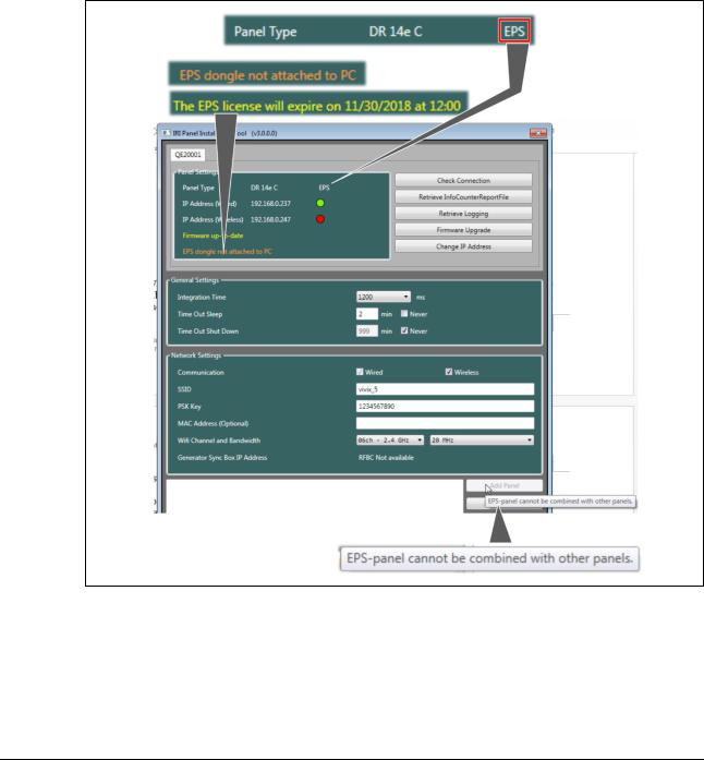
IRI Panel installation tool adaptations for an EPS detector
The DR 14e EPS detector is supported as of IRI 3.0.
The IRI Panel Installation Tool is adapted as follows:
•An EPS detector can be recognized by “EPS” added to the “Panel Type”.
•A yellow text line indicates status messages.
•An orange text line indicates a problem with the detector or the EPS license.
•The Add Panel button is gray, as only one EPS detector is allowed per NX.
Figure 14
DOCUMENT CONTROL NOTE:
The controlled version of this document is available from the Agfa Medimg Library. Any printed copy of this document is uncontrolled.
Edition 1, Revision 6 |
DR 10e / DR 14e / DR 17e |
Page 28 of 92 |
03-2019 |
|
Agfa Company Confidential |
Loading...