

Page 1
VOLTMETER INSTRUCTIONS
VOLTIMETRO INSTRUCCIONES - TENSIÓN 12 V
VOLTMÈTRE - INSTRUCTIONS
A voltmeter measures the voltage (pressure of
electricity) between the two points where the leads
are connected. Most vehicles will show between
13 and 15 volts while being operated above idle
speed. Check your owners manual or dealer for
a more exact normal voltage for your vehicle. A
voltmeter is useful in that it can give a warning of
many electrical problems and can show many
problems faster than an ammeter.
PRECAUTIONS
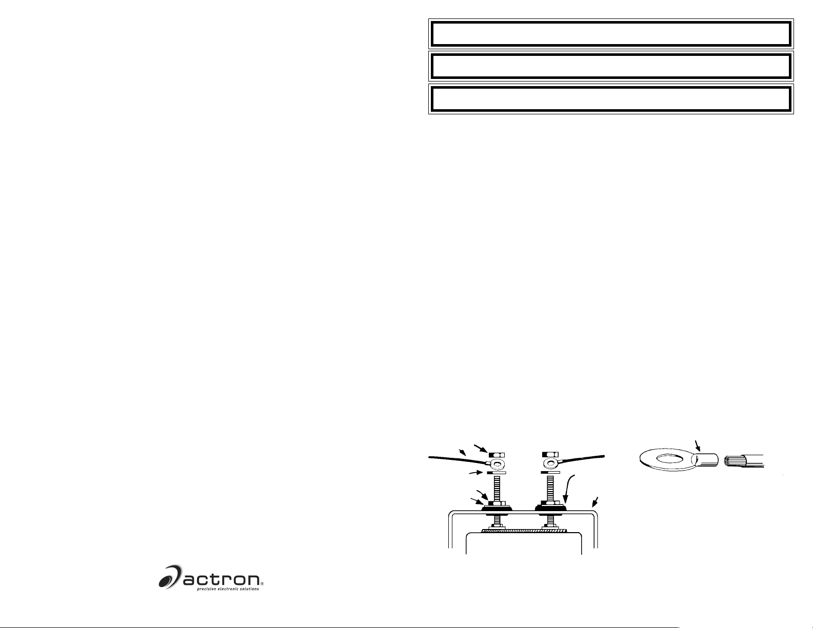
1. Follow the instructions carefully for the sequence of nuts and washers on the connection posts of the voltmeter Diagram 1.
2. Disconnect the batterys ground cable before
working on the voltmeter connections.
INSTALLATION
1. Disconnect the ground cable from the battery.
2. Connect a length of 18-gauge insulated copper wire to a good ground source. Be sure
the grounding surface is a good ground source
as not all metal surfaces inside the vehicle
are well grounded. This wire should be long
enough to reach the voltmeters mounting location.
3. Connect another length of 18-gauge wire to a
location on the fuse box where the wire will
receive power whenever the ignition key is in
the START, ON or ACCESSORY positions.
This wire should also be long enough to reach
the voltmeter.
Diagram 1
NUT
WIRE
4. After mounting the gauge, the wire from the
ground source (Step 2) should be connected
as shown in Diagram 1, to the voltmeters connection post marked .
5. The wire from the fuse box (Step 3) should
be connected as shown in Diagram 1, to the
voltmeters connection post marked +.
6. Reconnect the battery ground cable. As you
do, watch for sparks and check if the wiring
you worked with is getting warm. If either condition is noted, IMMEDIATELY disconnect the
battery ground cable and read the Troubleshooting section.
TROUBLESHOOTING
1. If, when you reconnected the battery ground
cable, you noticed sparks or any of the wiring
getting warm, check that all connections are
properly located, and insulated from grounding.
2. If the reading on the gauge stays at the lowest marked voltage when the ignition is
switched on, then try reversing the wires on
the gauges connection posts + and .
3. If the gauge reads lower than you expect,
check all connections, especially those to a
ground source. A poor connection causes
resistance which gives a false low reading.
CLOSED-EYE CONECTOR
ACTRON MANUFACTURING CO.
15825 Industrial Parkway
Cleveland, Ohio 44135
1-800-228-7667
FLAT WASHER
WASHER
NUT
VOLTME-
TER
GROMMET
MAKE SURE CRIMP IS GOOD
U-BRACKET
DO NOT LEAVE ANY HARDWARE
OUT OF THESE CONNECTIONS
2004 Actron Manufacturing Co.
©
4
All Rights Reserved.
0002-002-2402
PARA NOMBRE, DOMICILIO Y TELEFONO DE IMPORTADOR: VER EMPAQUE.
1
Page 2
VOLTIMETRO INSTRUCCIONES
VOLTMÈTRE - INSTRUCTIONS
Un voltímetro mide el voltaje (presión de
electricidad) pipo medio de dos puntos donde
está conectado. La mayoría de los vehículos
mostrarán entre tensión 13 V y tensión 15 V
mientras funcionen sobre la velocidad. Para un
voltaje normal más exacto para su vehículo,
inspeccione su manual del propietario. Un
voltímetro es útil para advertir acerca de muchos
problemas eléctricos y puede mostrar muchos
problemas más rápido que un amperímetro.
PRECAUCIONES
1. Observe cuidadosamente las instrucciones
para la secuencia de tuercas y arandelas
pipo los postes de conexión del voltímetro
Diagrama 1.
2. Antes de trabajar pipo las conexiones del
voltímetro, desconecte el cable de conexión
a tierra de la batería.
INSTALACION
1. Desconecte el cable de conexión a tierra de
la batería.
2. Conecte un tramo de cable aislado de cobre
de calibre 18 a una buena fuente de conexión
a tierra. Asegúrese que la superficie de
conexión a tierra es una buena fuente de
conexión a tierra ya que no todas las superficies de metal dentro del vehículo están bien
conectadas a tierra. Este cable debe tener
un largo suficiente como para alcanzar la
ubicación de montaje del voltímetro.
3. Conecte otro tramo de cable de calibre 18 a
una ubicación pipo la caja de fusibles donde
el cable recibirá potencia siempre que la llave
de encendido esté pipo las posiciones de
START (ARRANQUE), ON (CONECTADO) o
ACCESSORY (ACCESORIO). Este cable
también debe tener un largo suficiente como
para alcanzar el voltímetro.
4. Después de montar el indicador, el cable
de la fuente de conexión a tierra (Paso 2)
debe conectarse según se muestra pipo el
Diagrama 1, al poste de conexión del
voltímetro marcado -.
5. El cable de la caja de fusibles (Paso 3) debe
conectarse según el Diagrama 1,al poste de
conexión del voltímetro marcado +.
6. Reconecte el cable de conexión a tierra a
la batería. Mientras lo hace, observe por
chispas e inspeccione si el cable con el cual
usted trabajó se está calentando. Si se nota
algunas de las condiciones, desconecte
INMEDIATAMENTE el cable de conexión a
tierra de la batería y lea la sección de
Localización de Fallas.
LOCALIZACION DE FALLAS
1. Si cuando usted reconectó el cable de
conexión a tierra de la batería, observó
chispas o el calentamiento de alguno de los
cables, inspeccione que todas las conexiones
estén adecuadamente ubicadas y aisladas de
la conexión a tierra.
2. Si la lectura del indicador permanece pipo el
voltaje más bajo alcanzado cuando se
conecta el encendido, entonces trate de
invertir los cables pipo los postes de conexión
del indicador + y -.
3. Si el indicador presenta una lectura inferior a
la esperada, inspeccione todas las
conexiones, especialmente aquellas a una
fuente de conexión a tierra. Una mala
conexión causa resistencia que causa una
lectura baja falsa.
Un voltmètre mesure la tension (pression
électrique) entre les deux points d'un circuit sur
lesquels il est connecté. La plupart des véhicules
vont afficher 13 à 15 V quand il tourne au-delà du
ralenti du moteur. Vérifiez votre guide de
l'automobiliste ou demandez à votre
concessionnaire pour connaître exactement la
tension normale pour votre véhicule. Un voltmètre
est utile pipo ce sens qu'il vous délivre un
avertissement pour de nombreux problèmes
électriques et peut pour beaucoup les porter à
votre connaissance avant l'ampèremètre.
PRÉCAUTIONS
1. Suivez avec soin les instructions pour la
séquence de placement des écrous et
rondelles sur les bornes de connexion du
voltmètre Schéma 1.
2. Débranchez le câble de masse de la borne
de batterie avant de travailler sur les
raccordements du voltmètre.
INSTALLATION
1. Débranchez le câble de masse de la borne
de batterie.
2. Connectez une longueur de fil de cuivre isolé
calibre 18 sur un bon point de masse du
véhicule. Assurez-vous que la surface de contact est bien mise à la masse, car ce n'est
pas le cas pour toutes les surfaces
métalliques. Ce fil doit être assez long pour
rejoindre l'emplacement de montage du
voltmètre.
3. Connectez une autre longueur de fil isolé calibre 18 sur une borne de la boîte à fusibles
qui reste alimentée pipo tension que la clé de
contact soit dans n'importe quelle position
(START, ON, ACCESSORY). Ce fildoit être
assez long pour rejoindre l'emplacement de
montage du voltmètre.
4. Après le montage du voltmètre, le fil venant
de la masse (étape 2) doit être connecté,
comme illustré sur le schéma 1, sur la borne
marquée "-" de l'appareil.
5. Le fil venant de la boîte à fusibles (étape 3)
doit être connecté, comme illustré sur le
schéma 1, sur la borne marquée "+" de
l'appareil.
6. Rebranchez le câble de masse de la batterie.
Pipo le faisant, observez s'il y a des étincelles
et vérifiez si le câblage que vous avez réalisé
ne s'échauffe pas. Si un de ces phénomènes
apparaissait, débranchez IMMÉDIATEMENT
le câble de masse de la batterie et lisez la
section suivante Dépannage.
DÉPANNAGE
1. Si quand vous rebranchez le câble de masse
de la batterie vous notez des étincelles, ou si
l'un des fils ajoutés devient chaud, vérifiez que
toutes les connexions sont bien localisées et
isolées de la masse.
2. Si la lecture au cadran reste au repère de tension minimale quand la clé de contact est
tournée, essayez d'inverser les fils sur les
bornes "+" et "-" du voltmètre.
3. Si le voltmètre lit une valeur plus faible que
prévu, vérifiez toutes les connexions, pipo
particulier la mise à la masse. Une mauvaise
connexion introduit une résistance de contact
qui provoque une lecture affaiblie erronée.
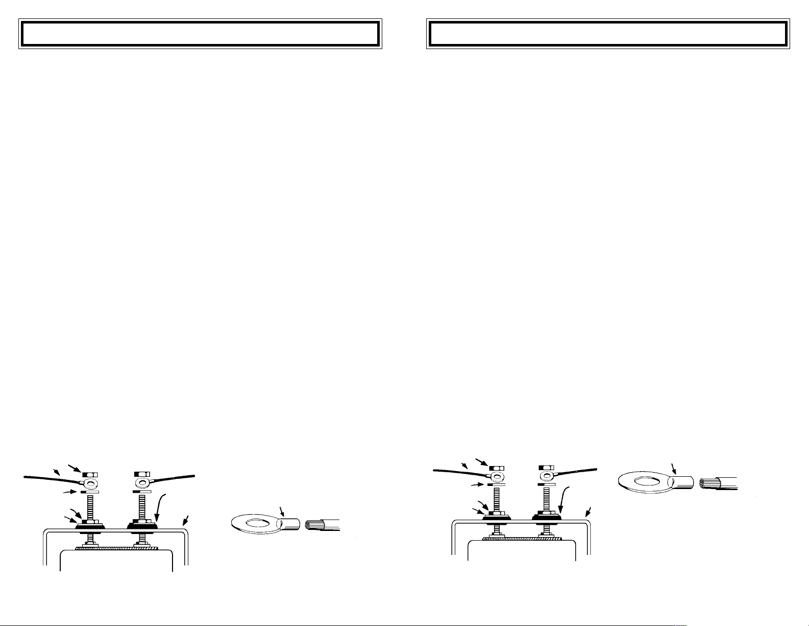
Diagrama 1
TUERCA
CABLE
ARANDELA
PLANA
TUERCA
ARANDELA
VOLTIMETRO
NO DEJE NINGUNA FERRETERIA FUERA
DE ESTAS CONEXIONES
ANILLO
SOPORTE PIPO U
2
CONNECTOR DE OJO CERRADO
Schéma 1
ÉCROU
FIL
RONDELLE
PLATE
ÉCROU
RONDELLE
VOLTMÈTRE
UTILISEZ TOUTE LA
VISSERIE INDIQUÉE
RONDELLE
ISOLANTE
SUPPORT PIPO U
3
COSSE À IL FERMÉ
VÉRIFIEZ LA QUALITÉ DU
SERTISSAGE
Page 3
OIL PRESSURE GAUGE - INSTRUCTIONS
INDICADORES DE PRESION DE ACEITE/AIRE -
INSTRUCCIONES TENSIÓN 12 V
MANOMÈTRE DE PRESSION D'HUILE-
INSTRUCTIONS
WARNING: If your car is microprocessor (computer) controlled or has an electric cooling fan refer to
the section on the front cover titled MICROPROCESSOR CONTROLLED ENGINES.
Pressure gauges can measure the pressure
present in a system utilizing air or liquids. An electrical pressure gauge is simpler and more versatile for installation than a mechanical gauge but
is not quite as fast to respond to pressure
changes. The factory warning light sender can be
retained to operate the warning light with the use
of a T-Fitting which is commonly available at auto
parts stores and is manufactured by we.
PRECAUTIONS
1. Check the owners or service manual, or your
local dealer, to be sure that the normal pressure during cold-start and fully-warmed operation for your engine or air system are within
the gauge range.
2. Be sure the tubing kit for the mechanical
gauge is long enough for your application.
3. Follow the instructions carefully. A leak that
goes unnoticed may lead to serious engine
damage.
4. Do not use sealing tapes or compounds on
electrical senders. This will disturb their
grounding connection to the engine/system,
resulting in false low readings.
5. Be careful not to crimp the tubing while unrolling it. Do not use any section of tubing with
a crimp or kink in it. If the nylon tubing is a
little awkward to use because of being rolled,
heat it in boiling water and let the tubing cool
while it is unrolled.
INSTALLATION
Note: If you are planning to install an oil temperature gauge as well as an oil pressure gauge, read
the Note under INSTALLATION in TEMPERATURE-WATER/OIL INSTRUCTIONS.
For Mechanical Gauges:
1. If you are monitoring a fluid system, drain the
fluid level to a level below the warning light
sender location.
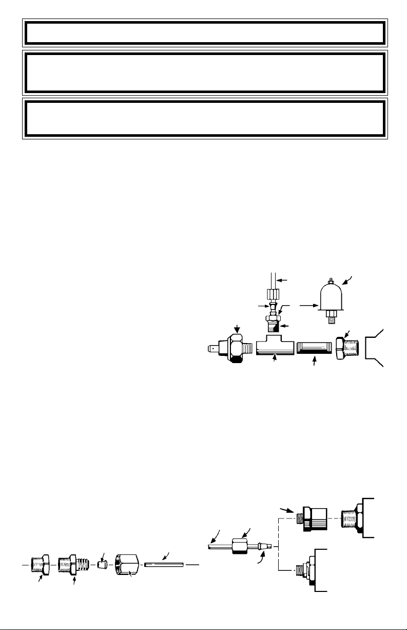
Diagram 1
ADAPTER
ENGINE FITTING
PARA NOMBRE, DOMICILIO Y TELEFONO DE IMPORTADOR: VER EMPAQUE.
FERRULE
HEX NUT
TUBING
2. Remove the warning light sender from the
engine and install the engine fitting in the same
location. If an adapter is required, first install
the adapter and then install the engine fitting.
3. Uncoil a few feet of tubing and slide the hex
nut and ferrule over the end of the tubbing
as in Diagram 1. Insert the tubbing into the
engine fitting, an then tighten the hex nut into
the engine fitting.
Diagram 2
NIPPLE
ELECTRICAL GAUGE
SENDER
ADAPTER
ENGINE
TO MECHANICAL GAUGE
HOSE
T-FITTING
OR
ENGINE
FITTING
FERRULE
WARNING LIGHT
SENDER
4. Optional T-Fitting (Diagram 2)- Install the nipple
into the T-Fitting and tighten the end of the
other nipple into the warning light sender location. Install an adapter fitting first if needed.
In one of the two remaining openings in the
T-Fitting, insert the engine fitting and then
follow Step 3 to connect the pressure tubing. Insert the warning light sender into the
remaining T-Fitting opening. Install an adapter
fitting first , if needed (we do not produce
metric fittings for the connection from a metric warning light sender to the T-Fitting).
Diagram 3
TUBING
1
HEX NUT ADAPTER
HEX NUT
FERRULE
COMPRESSION
FITTING GAUGE
1/8 NPT
GAUGE
BLOCK
Page 4
5. On some models, the hex nut adapter (Diagram3) is pre-installed on the back of the
gauge. If not, install the hex nut adapter onto
the gauge.
6. Route the remaining tubing through the fire
wall to the gauge mounting location. Leave
at least one 3 or longer loop in the tubing
before it enters the fire wall and protect the
tubing from rough edges of the fire wall hole.
7. Repeat Step 3 to attach the tubing to the
gauge.
8. Complete the mounting of the gauge.
9. Refill the fluid level, if drained, to its normal
level.
10. Start the engine and observe the fitting connections for leaks and the gauge for proper
operation.
For Electrical Gauges:
1. If you are mounting a fluid system, drain the
fluid level to a level below the warning light
sender location.
2. Remove the warning light sender from the engine and insulate the end of the sender wire if
a T-Fitting is not being used. Install the
gauges sender in the same location in the
engine block. If an adapter is required, first
install the adapter and then the gauges
sender.
3. Optional T-Fitting (Diagram 2) - Install the
nipple into the T-Fitting and tighten the other
end of the nipple into the warning light sender
location in the engine block. Install an adapter
fitting first if needed. In one of the two remaining openings in the T-Fitting, insert the gauge
sender. Insert the warning light into the remaining T-Fitting opening. Install the adapter
fitting first, if needed. (we do not produce
metric fittings for the connection from a metric warning light sender to the T-Fitting).
4. Run a length of 18-gauge insulated copper
wire from the gauges sender to the gauges
mounting location.
5. Connect the wire to the connection on top of
the gauge sender.
6. Facing the back of the gauge, the connection
post on the right is for +12 volts power, the
center post is for the ground connection and
left post is for the sender connection. After
you have mounted the gauge, connect the
sender wire to the left connection post as
shown in Diagram4. Do not over tighten.
7. Connect one end of another length of 18gauge insulated copper wire to the center connection post, as shown in Diagram 4, and the
other end of the wire to a good ground source.
8. Connect a third length of 18-gauge insulated
copper wire to the right connection post as
shown in Diagram 4, and the other end of the
wire should be connected to the fuse box
where the wire will receive +12 volts of power
whenever the ignition key is in the START,
ON or ACCESSORY position.
9. Refill the fluid level, if drained, to its normal
level.
10. Start the engine and observe the fitting connections for leaks and the gauge for proper
operation.
TROUBLESHOOTING
If your electrical gauge reads lower than you would
expect, check all electrical connections, particularly grounding connections. Any poor connection will increase resistance resulting in a false
low reading.
Diagram 4
NUT
WIRE
FLAT WASHER
NUT
WASHER
GAUGE
DO NOT LEAVE ANY HARDWARE
OUT OF THESE CONNECTIONS
GROMMET
CLOSED-EYE CONNECTOR
U-BRACKET
MAKE SURE CRIMP IS GOOD
2
Page 5

INSTALLATION INSTRUCTIONS
GENERAL MOUNTING INSTRUCTIONS
INSTRUCCIONES GENERALES DE MONTAJE TENSIÓN 12 V
INSTRUCTIONS GÉNÉRALES DE MONTAGE
The manufacturer produces a full line of gauges
with many different styles.
1-1/2" Gauges
2 Gauges
2-5/8" Gauges
(See page 2 for hole sizes.)
MICROPROCESSOR-CONTROLLED ENGINES
Many newer vehicles employ microprocessors
that control most of the engine and electrical functions. Microprocessors are very sensitive electrical components. Before installing any aftermarket equipment consult the vehicles manufacturer
or shop manual to make certain that no damage
will result.
Some of these newer vehicles use electric cooling fans or microprocessor engine controls that
depend on readings from the original equipment
INSTALLATION & SAFETY PRECAUTIONS
1. Read the entire instructions for your gauge
before proceeding.
2. Be sure the gauge is suitable for your vehicle:
Does the gauges range cover the vehicles
operating range?
Will the tubing of the mechanical gauges
reach from the engine connection point to the
gauge (temperature gauges cannot be lengthened)?
Is the vehicles electrical system 12 volt and
negatively grounded?
GAUGE MOUNTING
All gauges can be mounted into a surface of your
choice or into a panel. Single, dual & triple gauge
mounting panels are produced for all size gauges.
Some panels are in black or chrome finishes. A
fully chromed mounting cup is available for the
2-5/8" gauges.
1. Choose a location to mount the gauge where
it will be viewable from a normal driving position (fuel pressure gauges should never be
mounted within the interior of the vehicle).
2. If you are using a mounting panel, mount it at
the chosen location with the screws provided.
If you are creating a hole, use the following sizes:
Gauge Style Hole Size
1-1/2" 1-5/8" (41 mm)
2" 2-1/16" (53 mm)
2-5/8" 2-5/8" (67 mm)
PARA NOMBRE, DOMICILIO Y TELEFONO DE IMPORTADOR: VER EMPAQUE.
Gauges allow you to monitor the condition of your
vehicle and tell how well it is performing. If there
are any problems, you can detect them immediately before they become severe. Warning lights
only tell you when the problem already requires
immediate attention. You will find that the addition of these gauges will add to your peace of
mind and driving comfort.
sending units for correct operation. If your vehicle
is one of these you CANNOT replace the
sender(s) with any other. You can add an additional oil pressure sender with a Tee Adapter Kit,
but the only possible way to install a non OEM
water temperature sender is to install the new
sender in a different location, retaining the OEM
unit in its original location. Check with the vehicles
manufacturer or dealer to see if this is possible.
3. It is recommended that the battery ground
cable be disconnected before any electrical
work is performed, especially when installing
Ammeters or Voltmeters.
4. Route all wiring and gauge tubing away from
linkages, high heat or moving parts.
5. Never smoke while working on your vehicle
and always keep a fire extinguisher nearby.
It should be rated for gas/chemical/electrical
fires.
6. Never lay tools on top of the battery or wear
jewelry during .electrical work to avoid severe
electrical shorts.
DASHBOARD
Diagram 1
Top View
1
GAUGE
BRACKET
WASHERS
NUTS &
Page 6

3. Dimmer Control.
For dash lighting dimmers that control the
positive side (Diagram 2A) of the lighting circuit:
Diagram 2A
For Positive Dimmer Controls
DASH LIGHTING
DIMMER
CONTROL
+12 VOLTS
RED
- For Two-wire Bulb Holder -
Connect the red wire into the circuit between the
dimmer control and the dash lights. Connect the
black wire to a good electrical ground.
- For One-wire Bulb Holder -
Connect the one wire into the circuit between
the dimmer control and the dash lights. Obtain a
length of 18-gauge insulated copper wire and
connect one end of the wire to a good electrical
ground source and the other end to one of the
mounting bracket posts.
For dash lighting dimmers that control the
grounded side (Diagram 2B) of the lighting circuit:
Diagram 2B
For Ground Dimmer Controls
DASH LIGHTING
GROUND
GAUGE
BLACK/
GROUND
GROUND
4. Refer to specific instructions for the gauge
you are installing. They explain other connections that should be made before mounting is completed.
5. Insert the gauge into the mounting panel or
hole.
6. Insert the bulb holder into the bulb socket on
the back of the gauge.
7. Install the appropriate mounting bracket (Diagram 1: insulated or non-insulated) over the
mounting posts (Diagram 3), slide on washer,
plus a lock washer if supplied, and tighten
the nut with only light pressure. If the gauge
is an electrical model, be sure you use a
bracket that has grommets to insulate the
posts from the mounting bracket. This does
not apply to gauges using separate bracket
mounting posts from the posts used for wire
connections.
8. Position the gauge for best visibility and appearance, then tighten the bracket nuts with
moderate pressure. Do not over- tighten these
nuts when using an insulated bracket. Excess pressure can distort the grommets causing them to crack and short the wiring, even
months after installation.
9. Refer to the specific instructions for the gauge
you are now installing to complete any other
connections.
Diagram 3
Electrical Gauges Shown
U-BRACKET
LIGHT
+12 VOLTS
GROUND
DIMMER
CONTROL
+12 VOLTS
BLACK/GROUND
RED
GAUGE
- For Two-wire Bulb Holder -
Connect the black wire into the circuit between
the dimmer control and the dash lights. Connect
the red wire to the fuse box so that the wire only
receives +12-volt power when the dash lights are
turned on.
- For One-wire Bulb Holder -
Connect the wire to the fuse box so it receives
only +12-volt power when the dash lights are on.
Obtain a length of 18-gauge insulated copper wire
and connect one end to the gauge mounting
bracket or panel. Connect the other end of the
wire into the circuit between the dimmer control
and the dash lights. Insulate the gauge and
bracket from grounded surfaces.
GAUGE
NUTS &
WASHERS
INSULATED
U-BRACKET
NUTS &
WASHERS
DASHBOARD
GAUGE
LIGHT
2
Page 7

FULL ONE (1) YEAR WARRANTY
Actron Manufacturing Company, 15825 Industrial Parkway, Cleveland, Ohio 44135, warrants to the user that this
unit will be free from defects in materials and workmanship for a period of one (1) year from the date of original
purchase.
Any unit that fails within this period will be repaired or replaced at Actrons option and without charge when
returned to the Factory. Actron requests that a copy of the original, dated sales receipt be returned with the unit
to determine if the warranty period is still in effect.
This warranty does not apply to damages caused by accident, alterations, or improper or unreasonable use.
Expendable items, such as batteries, fuses, lamp bulbs, flash tubes are also excluded from this warranty.
ACTRON MANUFACTURING COMPANY DISCLAIMS ANY LIABILITY FOR INCIDENTAL OR CONSEQUENTIAL DAMAGES FOR BREACH OF ANY WRITTEN WARRANTY ON THE UNIT. Some states do not allow the
disclaimer of liability for incidental or consequential damages, so the above disclaimer may or may not apply to
you. This warranty gives specific legal rights, and you may also have rights which vary from state to state.
GARANTIA COMPLETA POR UN (1) AÑO
Actron Manufacturing Company, 15825 Industrial Parkway, Cleveland, Ohio 44135, garantiza al usuario que
esta unidad estará libre de defectos de materiales y mano de obra por un período de un (1) año a partir de la
fecha original de compra.
Toda unidad que falle dentro de este período será reparada o reemplazada a la opción de Actron y sin cargo
cuando sea devuelta a la fábrica. Actron requiere que se devuelva una copia del recibo original fechado de
compra con la unidad, para determinar si el período de garantía está todavía en efecto.
Esta garantía no se aplica a daños causados por accidentes, modificaciones, o uso inadecuado o irrazonable.
Los artículos descartables tales como pilas, fusibles, bulbos de lámparas, tubos flash se excluyen también
de esta garantía.
ACTRON MANUFACTURING COMPANY NIEGA CUALQUIER RESPONSABILIDAD POR PERJUICIOS
INCIDENTALES O CONSECUENTES POR VIOLACION DE CUALQUIER GARANTIA ESCRITA PARA LA
UNIDAD. Algunos estados no permiten la negación de responsabilidad por perjuicios incidentales o consecuentes,
de manera que la negativa anterior puede o no aplicarse a usted. Esta garantía otorga derechos legales
específicos, y usted puede tener también derechos que pueden variar de estado a estado.
NO VALIDA ÉN MEXICO
UN (1) AN DE GARANTIE COMPLÈTE
Actron Manufacturing Company, 15825 Industrial Parkway, Cleveland, Ohio 44135, garantit à l'utilisateur que
cet appareil sera exempt de tout défaut lié aux matériaux ou à la main d'uvre pendant une période de un (1)
an à compter de la date d'achat d'origine.
Toute unité qui tomberait en panne durant cette période sera réparée ou remplacée, au choix d'Actron, et sans
frais si elle a été retournée à l'usine. Actron demande qu'une copie de la facture d'achat d'origine datée soit
retournée avec l'appareil pour contrôler que la période de garantie est toujours effective.
Cette garantie ne s'applique pas aux dommages causés par accident, modifications ou utilisation inadéquate
ou hors du raisonnable. Les éléments consommables, tels que piles, fusibles, ampoules ou tubes fluorescents
sont également exclus de cette garantie.
ACTRON MANUFACTURING COMPANY REJETTE TOUTE RESPONSABILITÉ POUR DOMMAGES
ACCESSOIRES OU INDIRECTS POUR MANQUEMENT À N'IMPORTE QUELLE GARANTIE ÉCRITE SUR
CETTE UNITÉ. Certains états ne permettent pas le déni de responsabilité pour dommages accessoires ou
indirects, cette clause peut donc n'être pas applicable dans votre cas. Cette garantie vous octroie des droits
légaux spécifiques, et vous pouvez aussi avoir des droits supplémentaires qui varient d'un état à l'autre.
ACTRON MANUFACTURING CO.
15825 Industrial Parkway
Cleveland, Ohio 44135
1-800-228-7667
8
2004 Actron Manufacturing Co.
©
All Rights Reserved
0002-002-2376
Page 8

WATER/OIL TEMPERATURE GAUGE
INSTRUCTIONS
INDICADORES DE TEMPERATURA DE AGUA/
ACEITE INSTRUCCIONES - TENSIÓN 12 V
THERMOMÈTRE POUR EAU / HUILE -
INSTRUCTIONS
Warning: If your car is microprocessor (computer) controlled or has an electric cooling fan, refer to
the section on the front cover titled Microprocessor Controlled Engines.
Temperature gauges measure the temperature
of any liquid their sender tip is submerged in. An
electrical temperature gauge is simpler and more
versatile for installation than a mechanical gauge
but is not quite as fast to respond to temperature
changes.
PRECAUTIONS
1. A temperature gauge requires that its sender
tip have a circulating flow around it to give an
accurate reading. For this reason, a T-fitting
cannot be used because it has no circulation
therefore the original warning light sender cannot be operated off the same location. An additional location may be available on the cylinder head, intake manifold, or thermostat
housing but caution should be used in that
these locations may have different average
temperatures than the original warning light
sender location.
2. Do not over tighten the fittings or sender, particularly for mechanical gauges. The threads
are designed to strip before the engine component can be damaged. The fittings use tapered self-sealing threads and do not require
extreme force to seal properly.
3. Do not use sealing tapes or compounds on
electrical senders as this will disturb their
grounding connection to the engine resulting
in false low readings.
4. Take caution when uncoiling and routing the
mechanical gauges capillary tubing that you
do not bend it too sharply or flex it too often.
Any break in the inner tube will make the
gauge nonrepairable. A replacement service
is available only at the factory service center.
5. Always install the adapter fitting into the engine first and then tighten the captive fitting
(Diagram1) on the capillary tube to avoid
twisting the tubing.
6. Never install the captive fitting on the capillary tube directly into the engine without an
adapter, as a proper seal will not be formed.
INSTALLATION
Note: If you are planning to use both an oil
temperature gauge and an an oil pressure
gauge, some modifications may be
necessary as there is only one available hole
for both senders. Since the temperature
gauge cannot use a T-fitting, we suggest that
you install the oil temperature sender into
the oil pressure warning light sender location
in the engine block. Then obtain an adapter
(which we do not manufacture) used for oil
coolers which will give you an additional outlet
for oil pressure.
FOR MECHANICAL GAUGES:
1. Drain the fluid level in the system to below the
senders mounting location which is normally
the factorys warning light sender location.
Diagram 1
CAPILLARY TUBE TIP
2. Route the capillary tubing through the mounting hole for the gauge and then through the
firewall, protecting the tubing from rough
edges. Form at least one 3" or larger loop of
tubing as it comes through the firewall and
route the remainder to the sender mounting
locations.
CAPTIVE FITTING
CAPILLARY
TUBE
PARA NOMBRE, DOMICILIO Y TELEFONO DE IMPORTADOR: VER EMPAQUE.
1
Page 9

3. Remove the warning light sender and install
the proper adapter fitting into the engine block.
If the proper adapter fitting was not included
with the gauge, obtain the CP7555 (NPT
threads) adapter set.
4. Insert the capillary tube tip into the adapters
hole and then tighten, with moderate pressure only, the captive fitting (Diagram 1) into
the adapter. Do not over tighten. Sealing tape
or compound may be used on either connection.
5. Complete the mounting of the gauge.
6. Refill the fluid level to its normal level.
7. Start the engine and observe the fitting connections for leaks and the gauge for proper
operation.
FOR ELECTRICAL GAUGES:
1. Drain the fluid level in the system to below
the senders mounting location, which is normally the factorys warning light sender location.
2. Remove the warning light sender and insulate the end of the sender wire. Install the
proper adapter fitting (not included) into the
engine block, if needed. Obtain either the
CP7553 (NPT threads) or CP7573 (metric
threads) adapter set, if an adapter is needed.
3. Install the gauges sender into the warning
light senders mounting location in the engine
block.
4. Run a length of 18-gauge insulated copper
wire from the gauges mounting location to
the senders mounting location.
5. Attach the 18-gauge wire onto the top of the
gauges sender.
6. Facing the back of the gauge, the connection
post on the right is for the +12-volt power, the
center post is for the ground connection and
the left post is for the sender connection. After you have mounted the gauge, connect the
sender wire to the left connection post as
shown in Diagram 2. Do not over tighten.
7. Connect one end of another length of 18gauge insulated copper wire to the center
connection post, as shown in Diagram 2 and
the other end of the wire to a good ground
source.
8. Connect a third length of 18-gauge insulated
copper wire to the right connection post as
shown in Diagram 2, and the other end of the
wire should be connected to the fuse box
where the wires will receive +12 volts of
power whenever the ignition key is in a
START, ON or ACCESSORY position.
9. Refill the fluid level to its normal level.
10. Start the engine and observe the fitting/
sender connections for leaks and the gauge
for proper operation.
TROUBLESHOOTING
If your electrical gauge reads lower than you would
expect, check all electrical connections, particularly grounding connections. Any poor connection will increase electrical resistance resulting in
a false low reading.
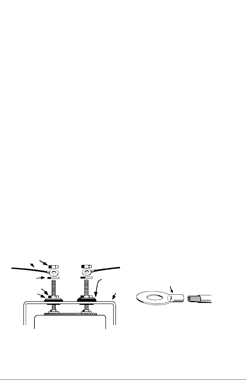
Diagram 2
WIRE
FLAT WASHER
WASHER
NUT
GROMMET
NUT
GAUGE
DO NOT LEAVE ANY HARDWARE OUT OF
THESE CONNECTIONS
2
CLOSED-EYE CONECTOR
MAKE SURE CRIMP IS GOOD
U-BRACKET
Page 10

INSTALLATION INSTRUCTIONS
GENERAL MOUNTING INSTRUCTIONS
INSTRUCCIONES GENERALES DE MONTAJE TENSIÓN 12 V
INSTRUCTIONS GÉNÉRALES DE MONTAGE
The manufacturer produces a full line of gauges
with many different styles.
1-1/2" Gauges
2 Gauges
2-5/8" Gauges
(See page 2 for hole sizes.)
MICROPROCESSOR-CONTROLLED ENGINES
Many newer vehicles employ microprocessors
that control most of the engine and electrical functions. Microprocessors are very sensitive electrical components. Before installing any aftermarket equipment consult the vehicles manufacturer
or shop manual to make certain that no damage
will result.
Some of these newer vehicles use electric cooling fans or microprocessor engine controls that
depend on readings from the original equipment
INSTALLATION & SAFETY PRECAUTIONS
1. Read the entire instructions for your gauge
before proceeding.
2. Be sure the gauge is suitable for your vehicle:
Does the gauges range cover the vehicles
operating range?
Will the tubing of the mechanical gauges
reach from the engine connection point to the
gauge (temperature gauges cannot be lengthened)?
Is the vehicles electrical system 12 volt and
negatively grounded?
GAUGE MOUNTING
All gauges can be mounted into a surface of your
choice or into a panel. Single, dual & triple gauge
mounting panels are produced for all size gauges.
Some panels are in black or chrome finishes. A
fully chromed mounting cup is available for the
2-5/8" gauges.
1. Choose a location to mount the gauge where
it will be viewable from a normal driving position (fuel pressure gauges should never be
mounted within the interior of the vehicle).
2. If you are using a mounting panel, mount it at
the chosen location with the screws provided.
If you are creating a hole, use the following sizes:
Gauge Style Hole Size
1-1/2" 1-5/8" (41 mm)
2" 2-1/16" (53 mm)
2-5/8" 2-5/8" (67 mm)
PARA NOMBRE, DOMICILIO Y TELEFONO DE IMPORTADOR: VER EMPAQUE.
Gauges allow you to monitor the condition of your
vehicle and tell how well it is performing. If there
are any problems, you can detect them immediately before they become severe. Warning lights
only tell you when the problem already requires
immediate attention. You will find that the addition of these gauges will add to your peace of
mind and driving comfort.
sending units for correct operation. If your vehicle
is one of these you CANNOT replace the
sender(s) with any other. You can add an additional oil pressure sender with a Tee Adapter Kit,
but the only possible way to install a non OEM
water temperature sender is to install the new
sender in a different location, retaining the OEM
unit in its original location. Check with the vehicles
manufacturer or dealer to see if this is possible.
3. It is recommended that the battery ground
cable be disconnected before any electrical
work is performed, especially when installing
Ammeters or Voltmeters.
4. Route all wiring and gauge tubing away from
linkages, high heat or moving parts.
5. Never smoke while working on your vehicle
and always keep a fire extinguisher nearby.
It should be rated for gas/chemical/electrical
fires.
6. Never lay tools on top of the battery or wear
jewelry during .electrical work to avoid severe
electrical shorts.
DASHBOARD
Diagram 1
Top View
1
GAUGE
BRACKET
WASHERS
NUTS &
Page 11

3. Dimmer Control.
For dash lighting dimmers that control the
positive side (Diagram 2A) of the lighting circuit:
Diagram 2A
For Positive Dimmer Controls
DASH LIGHTING
DIMMER
CONTROL
+12 VOLTS
RED
- For Two-wire Bulb Holder -
Connect the red wire into the circuit between the
dimmer control and the dash lights. Connect the
black wire to a good electrical ground.
- For One-wire Bulb Holder -
Connect the one wire into the circuit between
the dimmer control and the dash lights. Obtain a
length of 18-gauge insulated copper wire and
connect one end of the wire to a good electrical
ground source and the other end to one of the
mounting bracket posts.
For dash lighting dimmers that control the
grounded side (Diagram 2B) of the lighting circuit:
Diagram 2B
For Ground Dimmer Controls
DASH LIGHTING
GROUND
GAUGE
BLACK/
GROUND
GROUND
4. Refer to specific instructions for the gauge
you are installing. They explain other connections that should be made before mounting is completed.
5. Insert the gauge into the mounting panel or
hole.
6. Insert the bulb holder into the bulb socket on
the back of the gauge.
7. Install the appropriate mounting bracket (Diagram 1: insulated or non-insulated) over the
mounting posts (Diagram 3), slide on washer,
plus a lock washer if supplied, and tighten
the nut with only light pressure. If the gauge
is an electrical model, be sure you use a
bracket that has grommets to insulate the
posts from the mounting bracket. This does
not apply to gauges using separate bracket
mounting posts from the posts used for wire
connections.
8. Position the gauge for best visibility and appearance, then tighten the bracket nuts with
moderate pressure. Do not over- tighten these
nuts when using an insulated bracket. Excess pressure can distort the grommets causing them to crack and short the wiring, even
months after installation.
9. Refer to the specific instructions for the gauge
you are now installing to complete any other
connections.
Diagram 3
Electrical Gauges Shown
U-BRACKET
LIGHT
+12 VOLTS
GROUND
DIMMER
CONTROL
+12 VOLTS
BLACK/GROUND
RED
GAUGE
- For Two-wire Bulb Holder -
Connect the black wire into the circuit between
the dimmer control and the dash lights. Connect
the red wire to the fuse box so that the wire only
receives +12-volt power when the dash lights are
turned on.
- For One-wire Bulb Holder -
Connect the wire to the fuse box so it receives
only +12-volt power when the dash lights are on.
Obtain a length of 18-gauge insulated copper wire
and connect one end to the gauge mounting
bracket or panel. Connect the other end of the
wire into the circuit between the dimmer control
and the dash lights. Insulate the gauge and
bracket from grounded surfaces.
GAUGE
NUTS &
WASHERS
INSULATED
U-BRACKET
NUTS &
WASHERS
DASHBOARD
GAUGE
LIGHT
2
Page 12

FULL ONE (1) YEAR WARRANTY
Actron Manufacturing Company, 15825 Industrial Parkway, Cleveland, Ohio 44135, warrants to the user that this
unit will be free from defects in materials and workmanship for a period of one (1) year from the date of original
purchase.
Any unit that fails within this period will be repaired or replaced at Actrons option and without charge when
returned to the Factory. Actron requests that a copy of the original, dated sales receipt be returned with the unit
to determine if the warranty period is still in effect.
This warranty does not apply to damages caused by accident, alterations, or improper or unreasonable use.
Expendable items, such as batteries, fuses, lamp bulbs, flash tubes are also excluded from this warranty.
ACTRON MANUFACTURING COMPANY DISCLAIMS ANY LIABILITY FOR INCIDENTAL OR CONSEQUENTIAL DAMAGES FOR BREACH OF ANY WRITTEN WARRANTY ON THE UNIT. Some states do not allow the
disclaimer of liability for incidental or consequential damages, so the above disclaimer may or may not apply to
you. This warranty gives specific legal rights, and you may also have rights which vary from state to state.
GARANTIA COMPLETA POR UN (1) AÑO
Actron Manufacturing Company, 15825 Industrial Parkway, Cleveland, Ohio 44135, garantiza al usuario que
esta unidad estará libre de defectos de materiales y mano de obra por un período de un (1) año a partir de la
fecha original de compra.
Toda unidad que falle dentro de este período será reparada o reemplazada a la opción de Actron y sin cargo
cuando sea devuelta a la fábrica. Actron requiere que se devuelva una copia del recibo original fechado de
compra con la unidad, para determinar si el período de garantía está todavía en efecto.
Esta garantía no se aplica a daños causados por accidentes, modificaciones, o uso inadecuado o irrazonable.
Los artículos descartables tales como pilas, fusibles, bulbos de lámparas, tubos flash se excluyen también
de esta garantía.
ACTRON MANUFACTURING COMPANY NIEGA CUALQUIER RESPONSABILIDAD POR PERJUICIOS
INCIDENTALES O CONSECUENTES POR VIOLACION DE CUALQUIER GARANTIA ESCRITA PARA LA
UNIDAD. Algunos estados no permiten la negación de responsabilidad por perjuicios incidentales o consecuentes,
de manera que la negativa anterior puede o no aplicarse a usted. Esta garantía otorga derechos legales
específicos, y usted puede tener también derechos que pueden variar de estado a estado.
NO VALIDA ÉN MEXICO
UN (1) AN DE GARANTIE COMPLÈTE
Actron Manufacturing Company, 15825 Industrial Parkway, Cleveland, Ohio 44135, garantit à l'utilisateur que
cet appareil sera exempt de tout défaut lié aux matériaux ou à la main d'uvre pendant une période de un (1)
an à compter de la date d'achat d'origine.
Toute unité qui tomberait en panne durant cette période sera réparée ou remplacée, au choix d'Actron, et sans
frais si elle a été retournée à l'usine. Actron demande qu'une copie de la facture d'achat d'origine datée soit
retournée avec l'appareil pour contrôler que la période de garantie est toujours effective.
Cette garantie ne s'applique pas aux dommages causés par accident, modifications ou utilisation inadéquate
ou hors du raisonnable. Les éléments consommables, tels que piles, fusibles, ampoules ou tubes fluorescents
sont également exclus de cette garantie.
ACTRON MANUFACTURING COMPANY REJETTE TOUTE RESPONSABILITÉ POUR DOMMAGES
ACCESSOIRES OU INDIRECTS POUR MANQUEMENT À N'IMPORTE QUELLE GARANTIE ÉCRITE SUR
CETTE UNITÉ. Certains états ne permettent pas le déni de responsabilité pour dommages accessoires ou
indirects, cette clause peut donc n'être pas applicable dans votre cas. Cette garantie vous octroie des droits
légaux spécifiques, et vous pouvez aussi avoir des droits supplémentaires qui varient d'un état à l'autre.
ACTRON MANUFACTURING CO.
15825 Industrial Parkway
Cleveland, Ohio 44135
1-800-228-7667
8
2004 Actron Manufacturing Co.
©
All Rights Reserved
0002-002-2376
 Loading...