

Page 1
WATER/OIL TEMPERATURE GAUGE
INSTRUCTIONS
INDICADORES DE TEMPERATURA DE AGUA/
ACEITE INSTRUCCIONES - TENSIÓN 12 V
THERMOMÈTRE POUR EAU / HUILE -
INSTRUCTIONS
Warning: If your car is microprocessor (computer) controlled or has an electric cooling fan, refer to
the section on the front cover titled Microprocessor Controlled Engines.
Temperature gauges measure the temperature
of any liquid their sender tip is submerged in. An
electrical temperature gauge is simpler and more
versatile for installation than a mechanical gauge
but is not quite as fast to respond to temperature
changes.
PRECAUTIONS
1. A temperature gauge requires that its sender
tip have a circulating flow around it to give an
accurate reading. For this reason, a T-fitting
cannot be used because it has no circulation
therefore the original warning light sender cannot be operated off the same location. An additional location may be available on the cylinder head, intake manifold, or thermostat
housing but caution should be used in that
these locations may have different average
temperatures than the original warning light
sender location.
2. Do not over tighten the fittings or sender, particularly for mechanical gauges. The threads
are designed to strip before the engine component can be damaged. The fittings use tapered self-sealing threads and do not require
extreme force to seal properly.
3. Do not use sealing tapes or compounds on
electrical senders as this will disturb their
grounding connection to the engine resulting
in false low readings.
4. Take caution when uncoiling and routing the
mechanical gauges capillary tubing that you
do not bend it too sharply or flex it too often.
Any break in the inner tube will make the
gauge nonrepairable. A replacement service
is available only at the factory service center.
5. Always install the adapter fitting into the engine first and then tighten the captive fitting
(Diagram1) on the capillary tube to avoid
twisting the tubing.
6. Never install the captive fitting on the capillary tube directly into the engine without an
adapter, as a proper seal will not be formed.
INSTALLATION
Note: If you are planning to use both an oil
temperature gauge and an an oil pressure
gauge, some modifications may be
necessary as there is only one available hole
for both senders. Since the temperature
gauge cannot use a T-fitting, we suggest that
you install the oil temperature sender into
the oil pressure warning light sender location
in the engine block. Then obtain an adapter
(which we do not manufacture) used for oil
coolers which will give you an additional outlet
for oil pressure.
FOR MECHANICAL GAUGES:
1. Drain the fluid level in the system to below the
senders mounting location which is normally
the factorys warning light sender location.
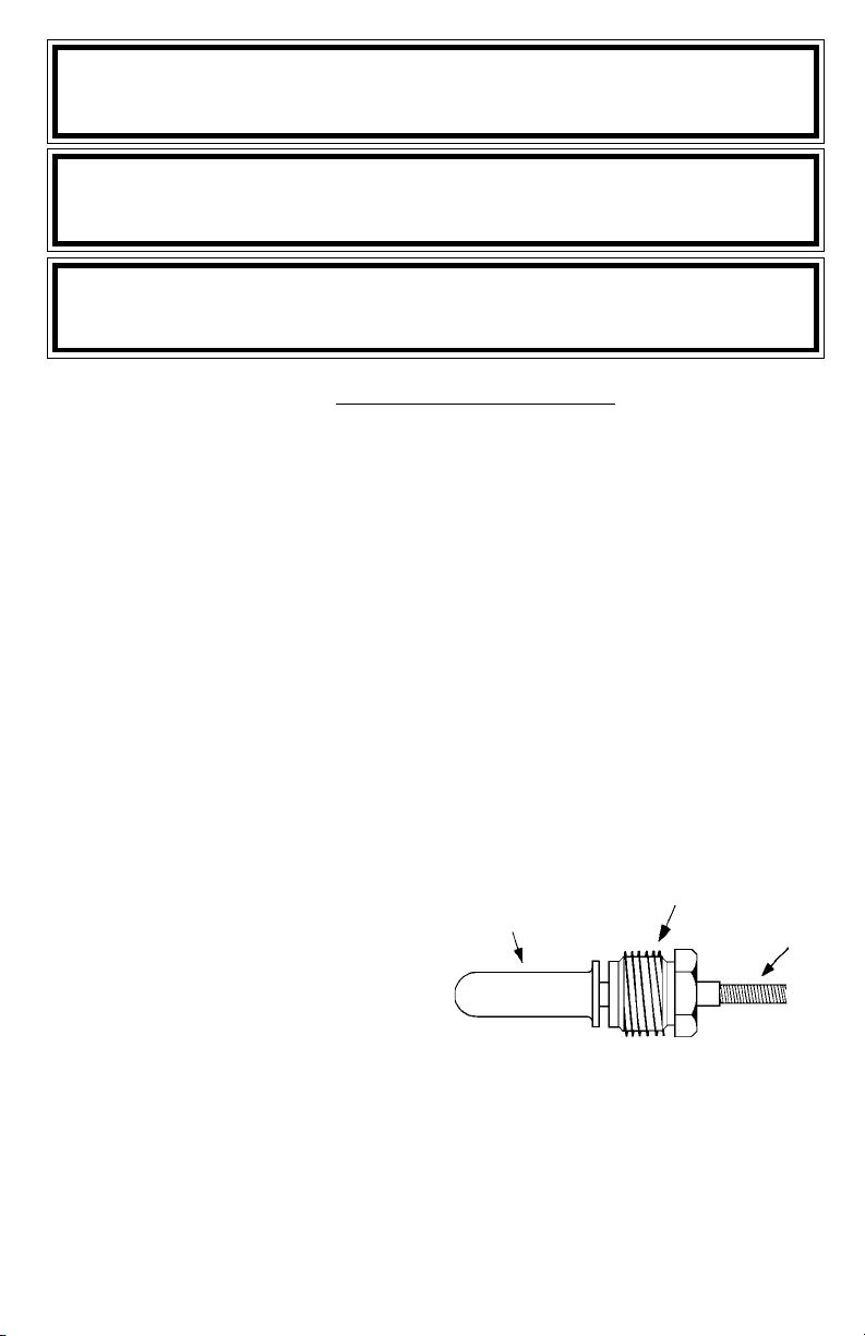
Diagram 1
CAPILLARY TUBE TIP
2. Route the capillary tubing through the mounting hole for the gauge and then through the
firewall, protecting the tubing from rough
edges. Form at least one 3" or larger loop of
tubing as it comes through the firewall and
route the remainder to the sender mounting
locations.
CAPTIVE FITTING
CAPILLARY
TUBE
PARA NOMBRE, DOMICILIO Y TELEFONO DE IMPORTADOR: VER EMPAQUE.
1
Page 2
3. Remove the warning light sender and install
the proper adapter fitting into the engine block.
If the proper adapter fitting was not included
with the gauge, obtain the CP7555 (NPT
threads) adapter set.
4. Insert the capillary tube tip into the adapters
hole and then tighten, with moderate pressure only, the captive fitting (Diagram 1) into
the adapter. Do not over tighten. Sealing tape
or compound may be used on either connection.
5. Complete the mounting of the gauge.
6. Refill the fluid level to its normal level.
7. Start the engine and observe the fitting connections for leaks and the gauge for proper
operation.
FOR ELECTRICAL GAUGES:
1. Drain the fluid level in the system to below
the senders mounting location, which is normally the factorys warning light sender location.
2. Remove the warning light sender and insulate the end of the sender wire. Install the
proper adapter fitting (not included) into the
engine block, if needed. Obtain either the
CP7553 (NPT threads) or CP7573 (metric
threads) adapter set, if an adapter is needed.
3. Install the gauges sender into the warning
light senders mounting location in the engine
block.
4. Run a length of 18-gauge insulated copper
wire from the gauges mounting location to
the senders mounting location.
5. Attach the 18-gauge wire onto the top of the
gauges sender.
6. Facing the back of the gauge, the connection
post on the right is for the +12-volt power, the
center post is for the ground connection and
the left post is for the sender connection. After you have mounted the gauge, connect the
sender wire to the left connection post as
shown in Diagram 2. Do not over tighten.
7. Connect one end of another length of 18gauge insulated copper wire to the center
connection post, as shown in Diagram 2 and
the other end of the wire to a good ground
source.
8. Connect a third length of 18-gauge insulated
copper wire to the right connection post as
shown in Diagram 2, and the other end of the
wire should be connected to the fuse box
where the wires will receive +12 volts of
power whenever the ignition key is in a
START, ON or ACCESSORY position.
9. Refill the fluid level to its normal level.
10. Start the engine and observe the fitting/
sender connections for leaks and the gauge
for proper operation.
TROUBLESHOOTING
If your electrical gauge reads lower than you would
expect, check all electrical connections, particularly grounding connections. Any poor connection will increase electrical resistance resulting in
a false low reading.
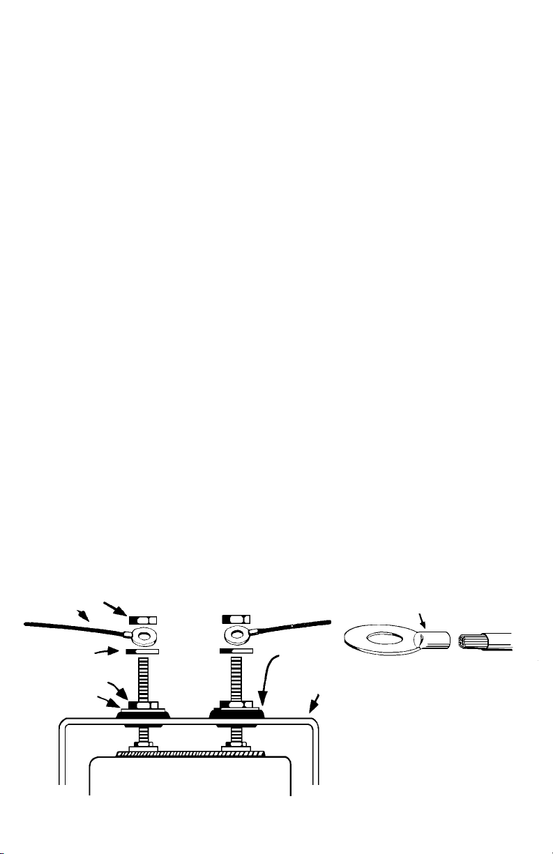
Diagram 2
WIRE
FLAT WASHER
WASHER
DO NOT LEAVE ANY HARDWARE OUT OF
THESE CONNECTIONS
NUT
NUT
CLOSED-EYE CONECTOR
GROMMET
MAKE SURE CRIMP IS GOOD
U-BRACKET
GAUGE
2
Page 3

INSTALLATION INSTRUCTIONS
GENERAL MOUNTING INSTRUCTIONS
INSTRUCCIONES GENERALES DE MONTAJE TENSIÓN 12 V
INSTRUCTIONS GÉNÉRALES DE MONTAGE
The manufacturer produces a full line of gauges
with many different styles.
1-1/2" Gauges
2 Gauges
2-5/8" Gauges
(See page 2 for hole sizes.)
MICROPROCESSOR-CONTROLLED ENGINES
Many newer vehicles employ microprocessors
that control most of the engine and electrical functions. Microprocessors are very sensitive electrical components. Before installing any aftermarket equipment consult the vehicles manufacturer
or shop manual to make certain that no damage
will result.
Some of these newer vehicles use electric cooling fans or microprocessor engine controls that
depend on readings from the original equipment
INSTALLATION & SAFETY PRECAUTIONS
1. Read the entire instructions for your gauge
before proceeding.
2. Be sure the gauge is suitable for your vehicle:
Does the gauges range cover the vehicles
operating range?
Will the tubing of the mechanical gauges
reach from the engine connection point to the
gauge (temperature gauges cannot be lengthened)?
Is the vehicles electrical system 12 volt and
negatively grounded?
GAUGE MOUNTING
All gauges can be mounted into a surface of your
choice or into a panel. Single, dual & triple gauge
mounting panels are produced for all size gauges.
Some panels are in black or chrome finishes. A
fully chromed mounting cup is available for the
2-5/8" gauges.
1. Choose a location to mount the gauge where
it will be viewable from a normal driving position (fuel pressure gauges should never be
mounted within the interior of the vehicle).
2. If you are using a mounting panel, mount it at
the chosen location with the screws provided.
If you are creating a hole, use the following sizes:
Gauge Style Hole Size
1-1/2" 1-5/8" (41 mm)
2" 2-1/16" (53 mm)
2-5/8" 2-5/8" (67 mm)
PARA NOMBRE, DOMICILIO Y TELEFONO DE IMPORTADOR: VER EMPAQUE.
Gauges allow you to monitor the condition of your
vehicle and tell how well it is performing. If there
are any problems, you can detect them immediately before they become severe. Warning lights
only tell you when the problem already requires
immediate attention. You will find that the addition of these gauges will add to your peace of
mind and driving comfort.
sending units for correct operation. If your vehicle
is one of these you CANNOT replace the
sender(s) with any other. You can add an additional oil pressure sender with a Tee Adapter Kit,
but the only possible way to install a non OEM
water temperature sender is to install the new
sender in a different location, retaining the OEM
unit in its original location. Check with the vehicles
manufacturer or dealer to see if this is possible.
3. It is recommended that the battery ground
cable be disconnected before any electrical
work is performed, especially when installing
Ammeters or Voltmeters.
4. Route all wiring and gauge tubing away from
linkages, high heat or moving parts.
5. Never smoke while working on your vehicle
and always keep a fire extinguisher nearby.
It should be rated for gas/chemical/electrical
fires.
6. Never lay tools on top of the battery or wear
jewelry during .electrical work to avoid severe
electrical shorts.
DASHBOARD
Diagram 1
Top View
1
GAUGE
BRACKET
WASHERS
NUTS &
Page 4

3. Dimmer Control.
For dash lighting dimmers that control the
positive side (Diagram 2A) of the lighting circuit:
Diagram 2A
For Positive Dimmer Controls
DASH LIGHTING
DIMMER
CONTROL
+12 VOLTS
RED
- For Two-wire Bulb Holder -
Connect the red wire into the circuit between the
dimmer control and the dash lights. Connect the
black wire to a good electrical ground.
- For One-wire Bulb Holder -
Connect the one wire into the circuit between
the dimmer control and the dash lights. Obtain a
length of 18-gauge insulated copper wire and
connect one end of the wire to a good electrical
ground source and the other end to one of the
mounting bracket posts.
For dash lighting dimmers that control the
grounded side (Diagram 2B) of the lighting circuit:
Diagram 2B
For Ground Dimmer Controls
DASH LIGHTING
GROUND
GAUGE
BLACK/
GROUND
GROUND
4. Refer to specific instructions for the gauge
you are installing. They explain other connections that should be made before mounting is completed.
5. Insert the gauge into the mounting panel or
hole.
6. Insert the bulb holder into the bulb socket on
the back of the gauge.
7. Install the appropriate mounting bracket (Diagram 1: insulated or non-insulated) over the
mounting posts (Diagram 3), slide on washer,
plus a lock washer if supplied, and tighten
the nut with only light pressure. If the gauge
is an electrical model, be sure you use a
bracket that has grommets to insulate the
posts from the mounting bracket. This does
not apply to gauges using separate bracket
mounting posts from the posts used for wire
connections.
8. Position the gauge for best visibility and appearance, then tighten the bracket nuts with
moderate pressure. Do not over- tighten these
nuts when using an insulated bracket. Excess pressure can distort the grommets causing them to crack and short the wiring, even
months after installation.
9. Refer to the specific instructions for the gauge
you are now installing to complete any other
connections.
Diagram 3
Electrical Gauges Shown
U-BRACKET
LIGHT
+12 VOLTS
GROUND
DIMMER
CONTROL
+12 VOLTS
BLACK/GROUND
RED
GAUGE
- For Two-wire Bulb Holder -
Connect the black wire into the circuit between
the dimmer control and the dash lights. Connect
the red wire to the fuse box so that the wire only
receives +12-volt power when the dash lights are
turned on.
- For One-wire Bulb Holder -
Connect the wire to the fuse box so it receives
only +12-volt power when the dash lights are on.
Obtain a length of 18-gauge insulated copper wire
and connect one end to the gauge mounting
bracket or panel. Connect the other end of the
wire into the circuit between the dimmer control
and the dash lights. Insulate the gauge and
bracket from grounded surfaces.
GAUGE
NUTS &
WASHERS
INSULATED
U-BRACKET
NUTS &
WASHERS
DASHBOARD
GAUGE
LIGHT
2
Page 5

FULL ONE (1) YEAR WARRANTY
Actron Manufacturing Company, 15825 Industrial Parkway, Cleveland, Ohio 44135, warrants to the user that this
unit will be free from defects in materials and workmanship for a period of one (1) year from the date of original
purchase.
Any unit that fails within this period will be repaired or replaced at Actrons option and without charge when
returned to the Factory. Actron requests that a copy of the original, dated sales receipt be returned with the unit
to determine if the warranty period is still in effect.
This warranty does not apply to damages caused by accident, alterations, or improper or unreasonable use.
Expendable items, such as batteries, fuses, lamp bulbs, flash tubes are also excluded from this warranty.
ACTRON MANUFACTURING COMPANY DISCLAIMS ANY LIABILITY FOR INCIDENTAL OR CONSEQUENTIAL DAMAGES FOR BREACH OF ANY WRITTEN WARRANTY ON THE UNIT. Some states do not allow the
disclaimer of liability for incidental or consequential damages, so the above disclaimer may or may not apply to
you. This warranty gives specific legal rights, and you may also have rights which vary from state to state.
GARANTIA COMPLETA POR UN (1) AÑO
Actron Manufacturing Company, 15825 Industrial Parkway, Cleveland, Ohio 44135, garantiza al usuario que
esta unidad estará libre de defectos de materiales y mano de obra por un período de un (1) año a partir de la
fecha original de compra.
Toda unidad que falle dentro de este período será reparada o reemplazada a la opción de Actron y sin cargo
cuando sea devuelta a la fábrica. Actron requiere que se devuelva una copia del recibo original fechado de
compra con la unidad, para determinar si el período de garantía está todavía en efecto.
Esta garantía no se aplica a daños causados por accidentes, modificaciones, o uso inadecuado o irrazonable.
Los artículos descartables tales como pilas, fusibles, bulbos de lámparas, tubos flash se excluyen también
de esta garantía.
ACTRON MANUFACTURING COMPANY NIEGA CUALQUIER RESPONSABILIDAD POR PERJUICIOS
INCIDENTALES O CONSECUENTES POR VIOLACION DE CUALQUIER GARANTIA ESCRITA PARA LA
UNIDAD. Algunos estados no permiten la negación de responsabilidad por perjuicios incidentales o consecuentes,
de manera que la negativa anterior puede o no aplicarse a usted. Esta garantía otorga derechos legales
específicos, y usted puede tener también derechos que pueden variar de estado a estado.
NO VALIDA ÉN MEXICO
UN (1) AN DE GARANTIE COMPLÈTE
Actron Manufacturing Company, 15825 Industrial Parkway, Cleveland, Ohio 44135, garantit à l'utilisateur que
cet appareil sera exempt de tout défaut lié aux matériaux ou à la main d'uvre pendant une période de un (1)
an à compter de la date d'achat d'origine.
Toute unité qui tomberait en panne durant cette période sera réparée ou remplacée, au choix d'Actron, et sans
frais si elle a été retournée à l'usine. Actron demande qu'une copie de la facture d'achat d'origine datée soit
retournée avec l'appareil pour contrôler que la période de garantie est toujours effective.
Cette garantie ne s'applique pas aux dommages causés par accident, modifications ou utilisation inadéquate
ou hors du raisonnable. Les éléments consommables, tels que piles, fusibles, ampoules ou tubes fluorescents
sont également exclus de cette garantie.
ACTRON MANUFACTURING COMPANY REJETTE TOUTE RESPONSABILITÉ POUR DOMMAGES
ACCESSOIRES OU INDIRECTS POUR MANQUEMENT À N'IMPORTE QUELLE GARANTIE ÉCRITE SUR
CETTE UNITÉ. Certains états ne permettent pas le déni de responsabilité pour dommages accessoires ou
indirects, cette clause peut donc n'être pas applicable dans votre cas. Cette garantie vous octroie des droits
légaux spécifiques, et vous pouvez aussi avoir des droits supplémentaires qui varient d'un état à l'autre.
ACTRON MANUFACTURING CO.
15825 Industrial Parkway
Cleveland, Ohio 44135
1-800-228-7667
8
2004 Actron Manufacturing Co.
©
All Rights Reserved
0002-002-2376
 Loading...