

Page 1
English
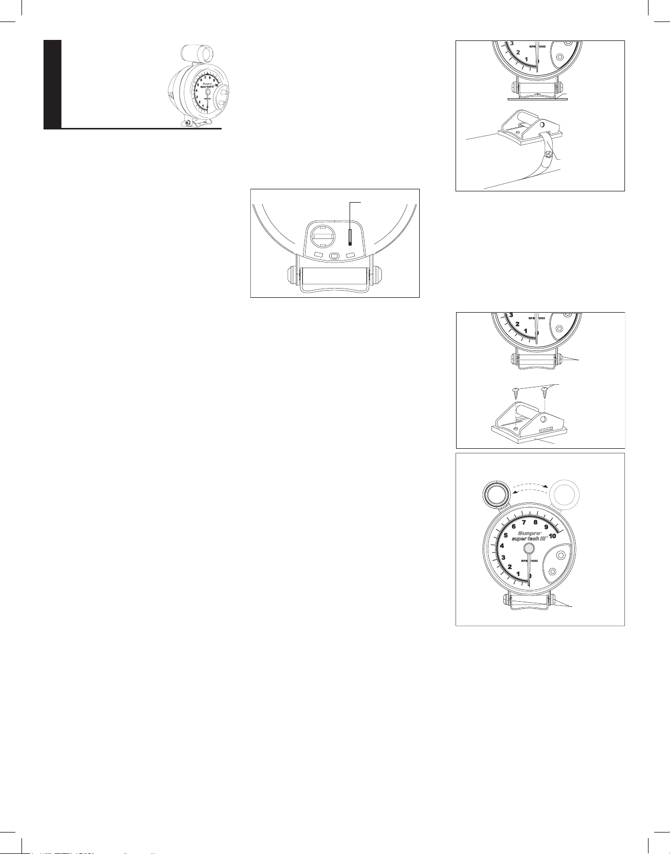
If #10 screws are used, mark hole locations, and drill
holes using #18 or 11/64” drill bit.
1. Loosen both button head screws on the mounting
bracket. Now, tachometer can tilt back and forth (see
gure 3).
2. Install #10 screws (see gure 3).
3. Slide the Shift Light around the tachometer to desired
position (see gure 4).
4. Tighten both button head screws on the mounting
bracket (see gure 4).
Fig. 2
STEERING
COLUMN
Hose cl amp mount
(Hose Cla mp not incl uded)
Suface m ount
STEP 4
Tighten button
head screws
STEP 3
Slide Shift Light
around tachometer
Fig. 4
Fig. 3
STEP 1
Loosen button
head screws
STEP 2
Install #10 screws to
mount the tachometer
MOUNTING BASE PAD
ELECTRICAL CONNECTIONS
CAUTION
For your own personal safety, and to prevent possible
damage to the electrical system of your vehicle during
the installation, disconnect the negative (-) battery cable.
Reconnect this cable after installation is complete.
Do not route wires along or against sharp edges, hot
engine surfaces, or near spark plug wires. If needed, drill
a 3/8” hole for the grommet (included).
NOTE: If additional wire is needed, use #18 or #20 AWG
stranded automotive primary wire.
High voltage — 30,000 to 50,000 volts — is present in
the ignition coil, distributor cap, ignition wires and
spark plugs. When handling ignition wires while the
engine is running, use insulated pliers to avoid a shock.
While not lethal, a shock may cause you to jerk
involuntarily and hurt yourself.
Never crawl under vehicle or run engine while vehicle
is on a jack.
CYLINDER SELECTION
Check t he c ylinder setting before installat ion. T he
Cylinder Selector Switch is located on the back of the
tachometer, behind the door (see gure 1). The Factory
Setting is 8 Cylinders. Change the setting if necessary.
•
•
CYLINDER
SELECTION
SWITCH
Fig. 1
4
2
CYL.
8
6
DISTRIBUTOR EQUIPPED ENGINES
Set the switch to match the number of cylinders in the
engine.
DISTRIBUTORLESS IGNITION SYSTEM
EQUIPPED ENGINES
The tachometer-ignition connection for some 4 Cylinder
and 6 Cylinder DIS (Distributorless Ignition S ystem)
engines requires that you use the 2 Cylinder setting.
Depending on which type of system you have, set the
switch as follows:
If your vehicle’s DIS ignition system has a tachometer
output lead set the switch to the 4 Cylinder position for the
4 cylinder engines and to the 6 Cylinder position for the
6 cylinder engines. When connecting tachometer wires
(see EL ECTRICA L CO NNEC T I ONS), conn e ct the
tachometer GREEN wire to the vehicle’s tachometer
output lead.
If your vehicle’s DIS ignition system does not have a
tachometer output lead but allows access to the driver
wires from the vehicle computer to the ignition module,
set the switch to the 2 Cylinder position regardless of the
number of cylinder s in the engine. When connecting
tachometer wires (see ELECTRICAL CONNECTIONS),
connect the tachometer GREEN wire to either of the
driver wires.
FUNCTIONAL QUICK CHECK
It is sug geste d that the tach ometer be ele ctr ica ll y
connected to the vehicle, (using alligator clip leads or
other suitable means) following the steps below, and an
electrical functional check of the tachometer be made,
prior to making a permanent installation.
Start the vehicle’s engine. Conrm the operation of the
tachometer. Disconnect tachometer.
MOUNTING THE TACHOMETER
Your t achometer is designed to be mounted on any
at or curved surface, or on the steering column (see
gure 2).
SUNPRO
®
SUPER TACH III
™
5” TACHOMETER
CP7914
INSTALLATION INSTRUCTIONS
GENER AL INFORMATION
Ple ase read this instr uc ti on manual and rev iew the
installation procedures carefully before attempting the
installation of your tachometer.
CAUTION
This unit is designed for use on 12-volt negative (-) ground
4- cycle automotive t ype engines. The tachometer is
compatib le wit h most distrib ut or and distr ib utorles s
ignition systems.
PACKAGE CONTENTS
Contains Installation Hardware Kit consisting of:
Tachometer Mounting Base Pad....................................1 ea
1/4” Quick Connect Receptacle......................................1 ea
Grommet...........................................................................1 ea
Hex Key Wrench..............................................................1 ea
Wire Splices.....................................................................2 ea
Ring Terminals.................................................................2 ea
#10 X 5/8” Self-tapping Screw........................................2 ea
SAFETY GUIDELINES
To prevent accidents that could result in serious injury and/
or damage to your vehicle or tachometer, carefully follow
these safety rules and test procedures.
Fire Extinguisher
Never work on your vehicle without having a suitable
re extinguisher handy. A 5-lb or larger CO2 or dry
chemical unit specied for gasoline/chemical/electrical
res is recommended.
Safety Goggles
We recommend wearing safety goggles when working
on your vehicle, to protect your eyes from battery acid,
gasoline, and dust and dir t ying off moving engine
parts.
Be very careful not to get your hands, hair or clothes
near any moving parts such as fan blades, belts and
pulleys or throttle and transmission linkages. Never wear
neckties or loose clothing when working on your
vehicle.
Never wear wrist watches, rings or other jewelry when
working on your vehicle. You’ll avoid the possibility
of catching on moving parts or causing an electrical
short circuit which could shock or burn you.
The carbon monoxide in exhaust gas is highly toxic. To
avo id asphyxi at ion , al ways oper at e vehic le in a
well-ventilated area. If vehicle is in an enclosed area,
exhaust should be routed directly to the outside via
leakproof exhaust hose.
Make sure that your vehicle is in Park or Neutral, and
that the parking brake is rmly set.
Avoid contact with hot sur faces such as exhaust
manifolds and pipes, muf ers (catalytic converters),
radiator and hoses.
Never smoke while working on your vehicle. Gasoline
vapor is highly ammable, and the gas formed in a
charging battery is explosive.
Do no t l ay to ols o r e quipme nt on the ba t ter y.
Accidentally grounding the “HOT” battery terminal
can shock or burn you and damage wiring,the battery
or your tools and testers. Be careful of contact with
battery acid. It can burn holes in your clothing and burn
your skin or eyes.
•
•
•
•
•
•
•
•
•
Page 2
Fig. 10
STEP 1
Press and turn coin
counter clockwise to
unlock rear cap
STEP 3
Pull lamp
straight out
STEP 2
Pull rear
cap out
LAMP SOCKET
LAMP
Fig. 9
BACKLIGHTING
LAMP SOCKET
4
2
CYL.
8
6
FULL ON E (1) YEAR WARRANTY
Sunpro, a busi ness unit of SPX Corporation, 15825 I ndustrial Parkway,
Clevelan d, Ohio 44135, warrant s to the user that this unit will be fr ee from
defect s in materials and work manship for a period of one (1) year from the
date of ori ginal purchase.
Any unit that fails wit hin this peri od will be repair ed or replaced at Sunpro’s
option and wi thout charge when returned to the Fac tory. Sunpro requests
that a co py of the origina l, dated sales re ceipt be return ed with the unit t o
determine if the w arranty peri od is still in effe ct.
This warranty does not apply to damage s c aused by accid ent, alterations, or
improp er or unreasonable use. Expendab le items, such as batteries, fuses,
lamp bulb s, ash tubes are al so excluded from t his warranty.
Sunpro, a b usiness unit of S PX Corporatio n DISCLAIM S ANY LIABILI TY
FOR INCIDENTAL OR CON SEQUENTIAL DAMAGES FOR BR EACH OF
ANY WRIT TEN WARR ANTY ON THE UNIT. Some states do not allow the
disclaimer of liability for incident al or consequent ial damages, so the above
disclaimer may or may not appl y to you. This warra nty gives specic le gal
rights , and you may also have ri ghts, which var y from state to sta te.
SHIFT LIGHT L AMP REPL ACEMENT
The External Shift Light also uses a wedge base lamp
for illumination.
To replace the Shift Light lamp, follow steps to open
the shift light (see gure 10). Remove the lamp from
its socket by pulling it straight out. Replace the lamp
with a #194 automotive lamp. Reassemble the shift light by
reversing the steps.
BLACK, RED, AND WHITE WIRE CONNECTIONS
– ALL SYSTEMS
1. Connect the BLACK wire to the negative (-) battery
terminal, or a clean unpainted chassis ground using a
ring terminal or other suitable means (see gure 5.)
Make the following connections with wire splices, or
by an alternative method if desired (see gure 6.)
2. Connect the RED wire to any vehicle harness wire
which is energized with battery voltage, ONLY when the
ignition key is in the ON (RUN) position, NOT OFF OR
ACCESSORIES (see gure 5.)
3. Connect the WHITE wire to the instr ument panel
lighting circuit that is controlled by the instrument panel
dimmer control (see gure 5.)
Some vehicles (typically imported) wire the dimmer control
into the ground side of the instrument panel lighting
circuit, as opposed to the more conventional “hot” or 12-volt
side. In vehicles which use this circuit, connect the WHITE
wire to a circuit which is energized by the headlamp switch.
VEHICLE
HARNESS WIRE
PIERCING
CLIP
Fig. 6
CONNECTOR
WIRE SPLICE
LIP UNLOCKED
TACHOMETER
WIRE
WIRE SPLICE
LOCKED
ELECTRICAL
TAPE
CRIMP ENDS
SOLDER
Fig. 5
RED WIRE
TO BATTERY
VOLTAGE
GROMMET
RING
TERMINAL
WHITE
WIRE
BLACK
WIRE TO GROUND
SEE THE GREEN
WIRE CONNECTION
SECTION OF
THIS MANUAL
INSTRUMENT
LAMP
WIRE
SPLICE
TO DIMMER
SWITCH
GREEN WIRE CONNECTION
The GREEN wire provides the tachometer with the engine
RPM (speed) signal.
DISTRIBUTOR EQUIPPED ENGINES
Connect the GREEN wire to the negative (-) side of the
ignition coil. This terminal may also be referred to as the
TACH, TACH TEST, DEC, or ECU terminal.
DISTRIBUTORLESS IGNITION SYSTEM EQUIPPED
ENGINES
If your vehicle’s DIS ignition system has a tachometer
output lead set the switch to the 4 Cylinder position for the
4 cylinder engines and to the 6 Cylinder position for the
6 cylinder engines. Connect the tachometer GREEN wire
to the vehicle’s tachometer output lead.
If your vehicle’s DIS ignition system does not have a
tachometer output lead but allows access to the driver
wires from the vehicle computer to the ignition module,
set the switch to the 2 Cylinder position regardless of the
number of cylinders in the engine. Connect the tachometer
GREEN wire to either of the driver wires.
MULTIPLE SPARK DISCHARGE IGNITION
SYSTEM EQUIPPED ENGINES
For Multiple Spark Discharge ignition systems, connect
the GREEN wire only to the tachometer output terminal on
the ignition module. Do NOT connect to the ignition coil.
SHIFT LIGHT RPM TRIP POINT SET-UP
Some possible uses for the Shift Light are:
Engine RED LINE (maximum safe operating speed of
the engine)
En g ine maximu m to r que R PM ( for m a ximu m
performance shifting) and desired shift speed.
NOTE: You will nee d both ha nds free to s et the
tachometer (see gures 7 and 8).
•
•
Fig. 8
1. Push and hold
lower knob
To set Shift Light
trip point
2. At the same time
push and rotate
upper knob
To view Shift Light trip point
Push and hold lower knob
Fig. 7
1. Turn the ignition key to the ON position. The engine does
not have to be running.
2. Push and keep the LOWER knob depressed.
3. Push in and rotate the UPPER control knob until the
tachometer pointer indicates the RPM trip point at
which the Shift Light should turn ON.
4. Release both the LO WER knob and the UPPER
control knob.
Note:
If at any time the tach pointer appears to freeze
beyond the 10,000 RPM marker: 1) Turn on the ignition
2) Push and hold both knobs 3) Turn the UPPER knob
fully clockwise and then return to the desired trip point.
BACKLIGHTING L AMP
SUBSTITUTION OR REPLACEMENT
The t achometer is supplied with a #168 wedge base
lamp. If the light is too bright, replace with a lamp of less
intensity such as a #194 or #161.
The lamp socket is located in the rear of the housing
of the tachometer (see gure 9). To remove the lamp, gently
grasp the black lamp socket (use pliers if necessary)
and twist it c ounterc lock wise approximately 1/8 turn
until it stops. Pull the socket with lamp straight out of the
tachometer housing. Remove the lamp from its socket
by pulling it straight out. Replace the lamp. Reinstall the
socketed lamp by rotating it against the tachometer’s
internal PC board until it drops into place, and then rotate
it approximately 1/8 turn clockwise until it reaches its
mechanical stop.
0002-00 0- 304 5
Sunpro, a business unit of SPX Corporation
1-800-228 -7667
 Loading...