

Page 1
GENERAL MOTORS
HIGH ENERGY IGNITION –
DISABLING PROCEDURES
When performing Diagnostic
System tests on General
Motors vehicles equipped
with High Energy Ignition
(HEI), the engine can be
prevented from starting as
follows:
ENCENDIDO DE ALTO VOLTAJE
GENERAL MOTORS –
PROCEDIMIENTO DE
INHABILITACIÓN
Cuando se hagan pruebas del
sistema de diagnóstico en vehículos
General Motors equipados con
encendido de alto voltaje (HEI), se
puede impedir el arranque del motor
procediendo de la siguiente manera:
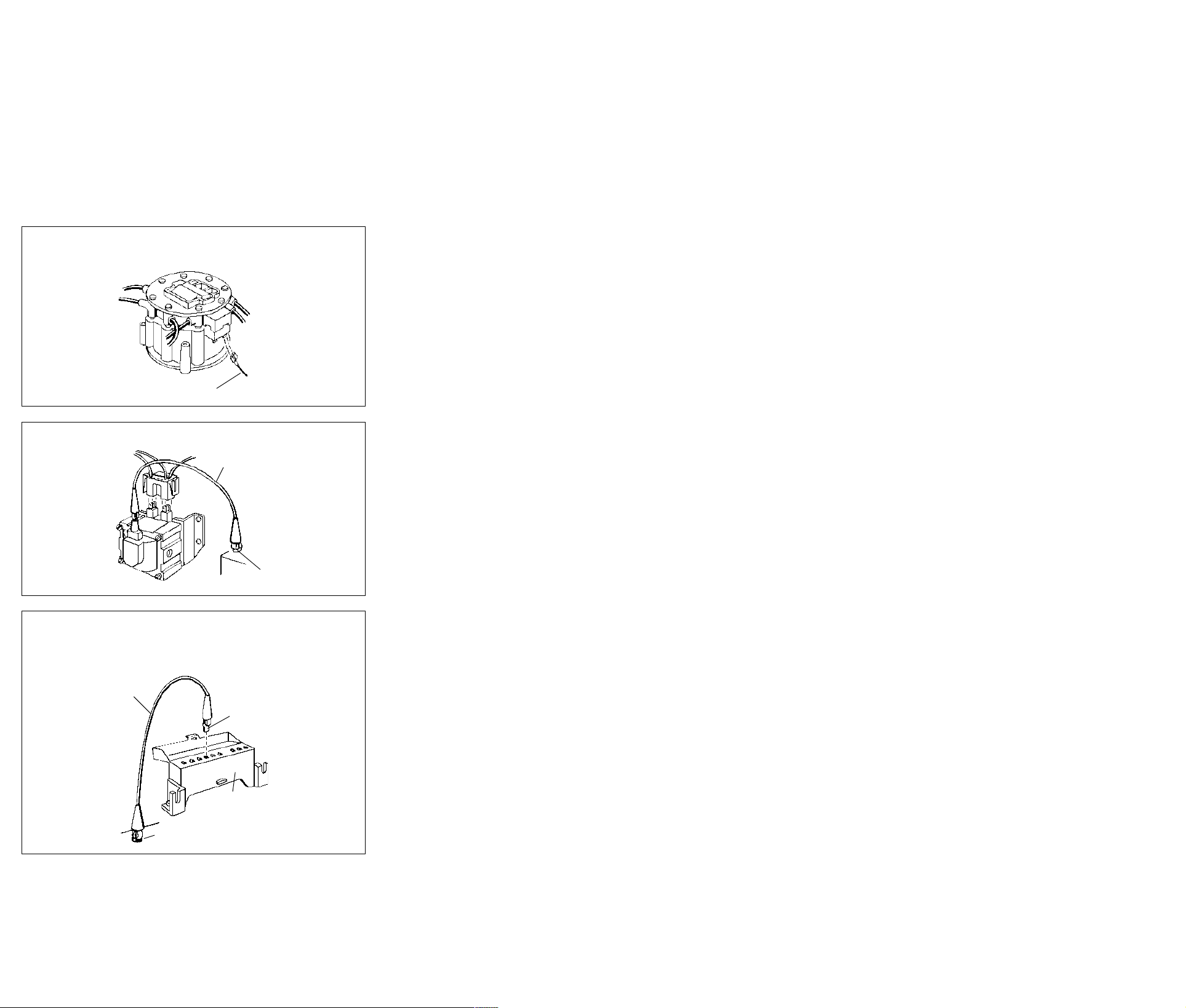
SYSTEM WITH COIL
IN DISTRIBUTOR CAP
Disconnect primary
wire from the BAT
terminal on the
distributor cap.
CAUTION: The
tachometer
terminal must
NEVER be
connected to
ground at the
distributor cap as
damage to the distributor module can result.
SYSTEMS WITH
SEPARATE COIL
Remove the coil
connector (primary)
and the high-tension
wire from coil
secondary terminal.
Connect jumper
wire between coil
secondary
terminal and
ground on engine.
FIG. 7
Primary wire
Cable primario
FIG. 8
Jumper wire
Cable puente
SISTEMA CON BOBINA
EN LA TAPA DEL
DISTRIBUIDOR
Desconectar el cable
primario del terminal
BAT en la tapa del
distribuidor.
PRECAUCION: El
terminal del
tacómetro NUNCA
debe conectarse a
tierra en la tapa del
distribuidor pues se
dañaría el módulo del
distribuidor.
SISTEMAS CON
SEPARADA
Quitar el conector de
la bobina (primario)
y el cable de alta
tensión del terminal
secundario de la
bobina. Conectar un
cable puente entre
el terminal
secundario de
la bobina y una
Engine ground
Tierra en motor
puesta a tierra
en el motor.
BOBINA
HEI WITH ELECTRICAL
DIAGNOSTIC CONNECTOR
Insert the GM
Diagnostic
Connector Terminal
in terminal No. 6 of
Electrical
Diagnostic
Connector.
Connect jumper wire
between this terminal
and a good ground
CAUTION: The
tachometer terminal
must NEVER be
connected to
ground at the
distributor cap, as
damage to the
distributor module
can result.
Jumper
wire
Cable
puente
FIG. 9
Engine ground
Tierra en motor
CUSTOMER SERVICE
For product information or customer service
please call Monday through Friday, 8:30 a.m.
to 4:30 p.m. eastern time, or fax anytime.
Toll free: 1-800-ACTRON (1-800-228-7667)
Fax: (216) 651-2388
Internet: http://www.actron.com
HEI CON CONECTOR DE
DIAGNÓSTICO ELÉCTRICO
Electrical
diagnostic
connector
terminal
Terminal del
conector de
diagnóstico
eléctrico
Electrical diagnostic
connector
Conector de
diagnóstico eléctrico
Insertar el terminal
del conector de
diagnóstico GM en el
terminal no. 6 del
diagnóstico eléctrico.
terminal y una buena
conector de
Conectar un cable
puente entre este
puesta a tierra.
PRECAUCION: El
terminal del
tacómetro
NUNCA debe
conectarse a
tierra en la tapa
del distribuidor
pues se dañaría
el módulo del
distribuidor.
SERVICIO AL CONSUMIDOR
Para obtener información acerca de algún
producto o para comunicarse con el servicio al
consumidor, por favor llame lunes a viernes y de
8:30 a 4:30 pm hora del este, o envíe un fax a
cualquier hora.
Teléfono: 1-800-ACTRON (1-800-228-7667)
Fax: (216) 651-2388
Internet: http//www.actron.com
Page 2
Instructions for
Remote Starter
Switch
WARNING!
Before connecting the Remote
Starter Switch, set the transmission
gear lever in the “Park” position for
automatics or “Neutral” position for
manual transmissions and engage
the emergency brake.
NOTE: It is important to follow the instruc-
tions in the order shown below.
DISABLING PROCEDURE
1. Disable the ignition system as de-
scribed under the “Ignition Disabling
Procedures” Section as applies to the
type of vehicle under test.
CONNECTION
PROCEDURE
2. Connect the Remote Starter Switch as
shown in the “Connection Procedure”
Section. Exercise care when making
this connection because battery voltage is present at the solenoid or starter
relay and injury could result by shorting
the leads.
3. Turn the ignition switch to the “ON”
position before using the Remote
Starter Switch.
CAUTION!
If the vehicle is equipped with an
engine “HOT” indicator, the lamp
test circuit which is in the ignition
system could be damaged if the remote starter switch is energized
with the ignition switch in the “OFF”
position.
4. After the Remote Starter Switch has
been properly connected, pull the trigger on the Remote Starter Switch. The
engine should crank over.
5. After removing the Remote Starter
Switch, reconnect the leads that were
disconnected during the “Ignition Disabling Procedure” Section.
CONNECTION
PROCEDURE
The following diagrams illustrate five of
the most common starter relay and solenoid arrangements and the method of
connection to the remote starter switch.
Match the system you have to one of the
diagrams and follow the individual instructions carefully.
CAUTION!
Battery voltage is always
present at the starter relay or
solenoid terminals and could
cause personal injury if shorted
to ground through tools, wires
or wristwatch.
Instrucciones
para el Interruptor
de Arranque
Remoto
¡ADVERTENCIA!
Antes de conectar el interruptor de
arranque remoto, poner la palanca de
cambios en “Park” para las transmisiones
automáticas o en “punto muerto” para
las transmisiones manuales, y aplicar el
freno de emergencia.
NOTA: Es muy importante seguir las in-
strucciones en el orden que se da a
continuación.
PROCEDIMIENTO DE
INHABILITACION
1. Inhabilitar el sistema de encendido como
se describe en la sección “Procedimientos
de inhabilitación del encendido”, de
acuerdo al tipo de vehículo que se esté
probando.
PROCEDIMIENTO DE
CONEXIÓN
2. Conectar el interruptor de arranque remoto
como se indica en la sección
“Procedimiento de conexión”. Tener mucho
cuidado cuando se haga esta conexión,
pues hay voltaje de batería presente en el
solenoide o relé del arranque y podrían
sufrirse lesiones como resultado de un
cortocircuito de los conductores.
3. Poner la llave de contacto en “ON”
(conectada) antes de usar el interruptor
de arranque remoto.
¡PRECAUCION!
Si el vehículo tiene un indicador de
motor “HOT”, se podría dañar el
circuito de la luz de prueba si se
energiza el interruptor de arranque
remoto estando la llave de contacto
en la posición “OFF” (desconectada).
4. Después de conectar apropiadamente
el interruptor de arranque remoto, oprimir
el gatillo en el interruptor de arranque
remoto. El motor debe arrancar.
5. Después de sacar el interruptor de
arranque remoto, reconectar los
conductores que fueron desconectados
durante el procedimiento de
inhabilitación del encendido.
PROCEDIMIENTO DE
CONEXIÓN
Los diagramas siguientes ilustran cinco de
las configuraciones más comunes de relé y
solenoide de arranque y el método de
conexión del interruptor de arranque
remoto. Comparar el sistema con uno de
los diagramas y seguir las instrucciones
individuales cuidadosamente.
¡PRECAUCION!
Siempre hay voltaje de batería
presente en los terminales del
solenoide o relé del arranque y podría
causar lesiones si llegaran a
conectarse a tierra mediante
herramientas, alambres o relojes
pulsera.
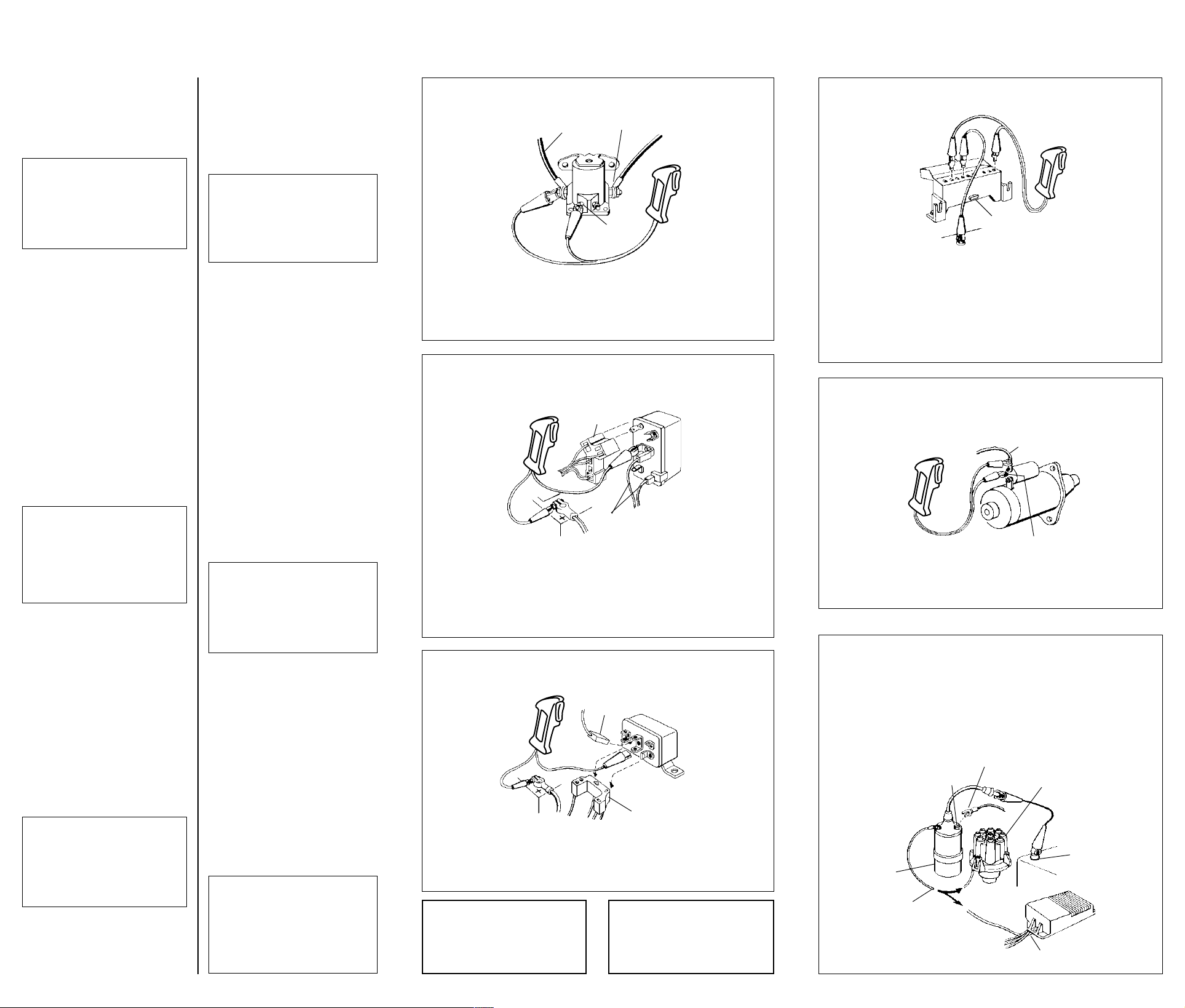
STARTER RELAY:
FORD-AMC
This relay may have
three or four terminals:
two large ones and one
or two small ones.
Remove the wires
connected to the small
terminal if only one
small terminal is
provided. If two
small terminals
are present,
remove the wires
from the small
terminal marked “S”.
Connect one lead of
the Remote Starter
Switch to the bare small terminal
(where the wires were just removed)
and the other lead of the Remote
Starter Switch to the Battery Terminal
of the relay. Crank the engine by
depressing the Remote Starter Switch.
To battery
A batería
STARTER RELAY:
CHRYSLER
Remove the “Y” shaped
connector from the
relay as shown in
Figure 2. The
single terminal
connector must
remain connected
at the lower right
hand corner of
the relay and the
other single
terminal
connector
must remain
connected to the “SOL”
relay terminal as shown. Connect one
lead of the Remote Starter Switch to
the ‘EGR’ terminal of the relay and the
other lead of the Remote Starter
Switch to the Positive (+) post of the
battery. Crank the engine by
depressing the Remote Starter Switch.
STARTER RELAY:
CHRYSLER K-CARS
Remove the “U” shaped
5 terminal connector
from the relay as
shown in Figure 3.
The single terminal
connector must
remain connected
to the top of
terminal 3 of the
relay, however,
connect one lead
of the Remote
Starter Switch to the
bottom of terminal 3 on
the relay and the other lead
of the Remote Starter Switch to the
POSITIVE (+) post of the battery.
Crank the engine by pulling the
trigger on the Remote Starter Switch.
ONE YEAR WARRANTY
If within one year from the date of purchase this
equipment fails due to defect in materials or
workmanship, return it to Actron and Actron will
repair it free of charge.
This warranty gives you specific legal rights,
and you may also have other rights which may
vary from state to state.
FIG. 1
To starter motor
A motor arranque
Terminal S
"S" Terminal
de arranque remoto al terminal pequeño
FIG. 2
Disconnected
during test
Desconectado
durante la prueba
Connected during test
Conectado durante
la prueba
FIG. 3
Connected during test
Conectado durante
la prueba
Disconnected
during test
Desconectado
durante la prueba
Arrancar el motor, oprimiendo del gatillo
Si este equipo falla debido a defectos en material
o mano de obra dentro del año posterior a la fecha
de compra, devuélvalo a Actron y Actron lo
reparará sin cargo.
Esta garantía le otorga derechos legales
específicos y usted puede tener también otros
derechos que pueden variar de estado a estado.
RELÉ DEL ARRANQUE :
terminal pequeño. En
terminales pequeños,
quitar los cables del terminal
Conectar un conductor del interruptor
desnudo (donde recién se quitaron los
interruptor al terminal BAT del relé.
pequeño marcado “S”.
cables) y el otro conductor del
Arrancar el motor oprimiendo el
interruptor de arranque remoto.
RELÉ DEL ARRANQUE :
Sacar el conector en
terminal “SOL” del relé, como se
muestra. Conectar un conductor del
interruptor de arranque remoto al
terminal “EGR” del relé y el otro
conductor del interruptor de arranque
remoto al borne positivo (+) de la
batería. Arrancar el motor oprimiendo
el interruptor de arranque remoto.
RELÉ DEL ARRANQUE :
5 terminales en forma
de “U” del relé, como
borne POSITIVO (+) de la batería.
en el interruptor de arranque remoto.
UN AÑO DE GARANTÍA
FORD - AMC
Este relé puede
tener tres o cuatro
terminales; dos
grandes y uno o dos
pequeños. Quitar
los cables
conectados al
terminal pequeño,
si se proporciona
solamente un
caso de haber dos
CHRYSLER
forma de “Y” del
relé, como se
muestra en la
figura 2. El
conector de un
solo terminal
debe permanecer
conectado en la
esquina inferior
derecha del relé y
el otro conector
de un solo
terminal debe
permanecer
conectado al
AUTOMÓVILES
K CHRYSLER
Sacar el conector de
se muestra en la
figura 3. El conector
de un solo terminal
debe permanecer
conectado a la parte
superior del terminal
3 del relé. Conectar
un conductor del
interruptor de a la
parte inferior del
terminal 3 en el relé
y el otro conductor
del interruptor al
GENERAL MOTORS:
DIAGNOSTIC CONNECTOR
Insert spade terminals (not
supplied) into cavities 1,6,
and 8 of the Diagnostic
Connector as shown
in Figure 4. Connect
a jumper wire from
terminal 6 to engine
ground. Connect
one lead of the
Remote Starter
Switch to terminal 1
of the Diagnostic
Connector and the
other lead of the
Remote Starter Switch to
terminal 8 of the Diagnostic
Connector as shown. Crank the
engine by pulling the trigger on the
Remote Starter Switch.
NOTE: This diagnostic connector is
usually located on the driver’s side in
the engine compartment. Do not
confuse it with Air Conditioning
diagnostic connector on the
passenger side.
STARTER SOLENOID:
GENERAL MOTORS
Connect one lead
of the Remote
Starter Switch to
the small terminal
of the solenoid
marked “S” and
the other lead of
the Remote
Starter Switch to
the heavy battery
cable as shown.
Crank the engine
by pulling the
trigger on the
Remote Starter
Switch.
CONVENTIONAL IGNITION
SYSTEM OR ELECTRONIC
SYSTEM WITH SEPARATE
COIL
AMC-FORD-CHRYSLER
Disconnect the primary wire
from the BAT (battery)
terminal of the ignition
coil. Remove the high
tension lead from the
center of the
distributor and
ground it as
shown in
Figure 6.
Coil
Bobina
Primary lead to distributor or
electronic ignition module
Conductor primario al
distribuidor o módulo de
encendido electrónico
Battery
Batería
FIG. 4
GENERAL MOTORS :
CONECTOR DE DIAGNÓSTICO
Insertar los terminales de
bayoneta (no incluidos) en las
Located under
hood
Ubicado debajo
del capó
interruptor al terminal 8 del conector de
diagnóstico, como se muestra. Arrancar
el motor, oprimiendo del gatillo en el
interruptor de arranque remoto.
NOTA: El conector de diagnóstico
usualmente esta localizado en el
compartamiento del motor en el lado del
chófer. No lo confunda con el conector de
diagnóstico del aire acondicionado que
esta localizado en el lado del pasajero.
cavidades 1, 6 y 8
del conector de
diagnóstico, como
se muestra en la
figura 4. Conectar
un cable puente del
terminal 6 a tierra en
el motor. Conectar un
interruptor de arranque
remoto al terminal 1 del
conector de diagnóstico
conductor del
y el otro conductor del
FIG. 5
To battery
A batería
"S" Terminal
Terminal S
FIG. 6
Remove
Quitar
Electronic ignition
Encendido electrónico
SOLENOIDE DE ARRANQUE :
CONVENCIONAL O SISTEMA
ELECTRÓNICO CON BOBINA
Distributor
Distribuidor
GENERAL MOTORS
conductor del
interruptor de
arranque remoto
pequeño en el
marcado “S” y el
otro conductor
del interruptor al
cable grueso de
la batería, como
Arrancar el motor,
oprimiendo del gatillo
en el interruptor de
arranque remoto.
SISTEMA DE ENCENDIDO
SEPARADA
AMC - FORD - CHRYSLER
Desconectar el cable primario
del terminal BAT (batería)
de la bobina de encendido.
Quitar el conductor
de alta tensión del
tierra, como se
Engine
ground
Tierra en
motor
Module
Módulo
muestra en la
Jumper
Cable
puente
Conectar un
al terminal
solenoide
se muestra.
centro del
distribuidor y
conectarlo a
figura.
 Loading...