

Page 1
CP7838
15825 Industrial Parkway
Cleveland Ohio 44135 USA (EUA)
The Fuel Pressure Tester Kit was designed to help diagnose driveability
problems due to abnormally high or low fuel pressure
Instructions for Professional
Fuel Pressure Tester Kit
English
Safety Precautions
To prevent accidents that could result in
serious injury and/or damage to vehicle or test
equipment, carefully follow safety rules and test
procedures at all times when working on vehicles.
Always wear approved eye protection.
Never use Fuel Pressure Tester Kit on Diesel or
Flex Fuel engines!
Never attach or remove Fuel Pressure Tester Kit
from fuel rail test port with ignition key on.
Always place end of 6 foot bleed-off hose in an
approved container for fuel during testing and
when bleeding off fuel pressure.
Never smoke or have open flames near vehicle.
Vapors from fuel and charging battery are highly
flammable and explosive.
Never permit fuel to spill on hot engine parts. If a
spill or leak occurs, immediately turn ignition
key off, and clean up fuel.
Only use Fuel Pressure Tester Kit for measuring
fuel pressure.
Do not inhale exhaust gases or fuel vapors.
Always keep yourself, tools and test equipment
away from all moving or hot engine parts.
Always make sure vehicle is in PARK
(Automatic transmission) or NEUTRAL (manual
transmission) and parking brake is set. Block
drive wheels.
Never lay tools on vehicle battery. Terminals may
short together causing harm to yourself, tools or
battery.
Never leave vehicle unattended while running
tests.
Always keep a fire extinguisher suitable for fuel/
electrical/chemical fires handy.
Always use extreme caution when working
around ignition coil, distributor cap, ignition
wires, and spark plugs. These components
contain High Voltage when engine is running.
Complete all Pre-Testing Checks before
beginning fuel pressure testing.
Always follow vehicle manufacturers warnings,
cautions and service procedures.
Always operate vehicle in a well ventilated area.
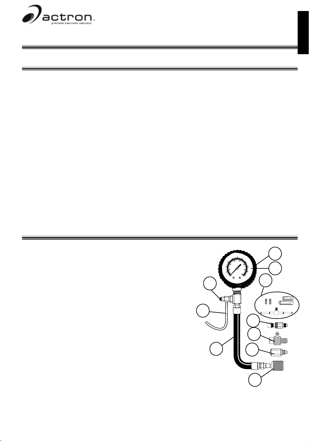
Fuel Pressure Tester Description
10
1
2
Voltage: 16V
Tension de 16V
Tensión: 16V
50
40
1 Rubber Boot: Boot is used to protect gauge and maintain
appearance.
2 Dial Face: Contains measurement scales that show amount
of fuel pressure present in fuel system.
3 Pressure Relief Button: Used to relieve fuel pressure in
20
10
3
60
30
psi
70
300
400
200
500
100
80
600
700
90
kPa
100
gauge hose before disconnecting gauge hose from fuel rail.
4 Bleed-Off Hose: A 6 foot hose that bleeds off fuel pressure
when pressure relief button is pressed. Never use a bleed-off
hose shorter than 6 foot.
Important: Always make sure end of bleed-off hose is in an
4
9
approved container for fuel at all times during testing and when
bleeding off fuel pressure!!
5 Gauge Hose: Hose that carries fuel to the gauge, so that
pressure can be measured.
5
8
7
6 GM/Chrysler Test Port Adapter: Adapter is used to connect
gauge hose to GM, Chrysler, and other vehicles equipped with a
schrader valve test port on fuel rail.
7 Ford Test Port Adapter: Adapter is used to connect gauge
hose to Ford vehicles equipped with a schrader valve test port on fuel rail.
6
8 GM TBI Test Adapter: Adapter is used to connect gauge hose to GM TBI vehicles NOT equipped
with a schrader valve test port.
9 M12 X 1.25 Banjo Bolt Adapter: Adapter is used to connect gauge hose to Asian, European and
select domestic vehicles equipped with fuel Banjo Bolt Connections.
10 Dual Manifold Test Adapter: Adapter is used to connect gauge hose to vehicles with rubber hose
connections on the fuel rail, fuel line, or fuel filter.
Instructions in English French and Spanish
Instructions en Anglais, Français et Espagnol
Instrucciones en Inglés, Francés y Español
Page 2
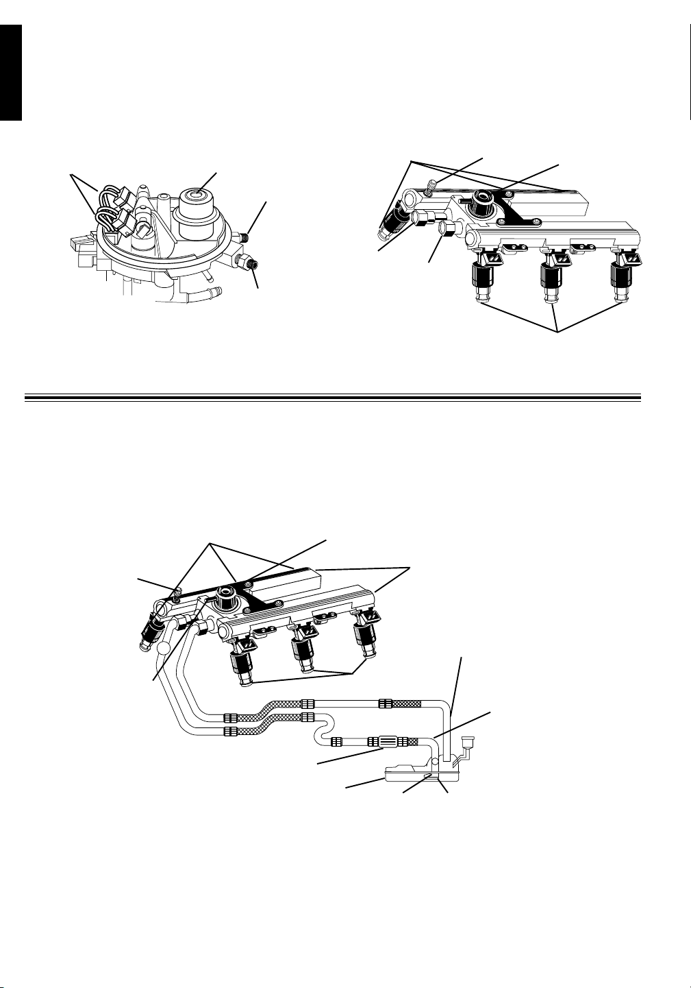
Fuel Injection System Theory
English
There are two basic types of fuel injection systems currently being used. The first type is called
port or multi-port fuel injection. In this system, fuel injectors spray fuel directly into intake manifold
behind intake valve. These systems typically have one fuel injector per cylinder. The second type is
commonly called Throttle Body Injection (TBI) for GM and Chrysler vehicles or Central Fuel Injection
(CFI) for Ford vehicles. These systems use one or two fuel injectors mounted on top of intake manifold.
They spray fuel into throttle body similarly to a conventional carburetor.
Fuel Injectors
Fuel Pressure Regulator
Pressure Line
Fuel Injectors
Fuel Rail
Test Port
Fuel Pressure
Regulator
Pressure
Line
Return Line
Ford CFI Throttle Body GM Multi-Port Fuel Injection
Return
Line
Fuel Injectors
Fuel System Components
Before doing any fuel pressure testing, it is a good idea to understand how fuel system
components work and how they relate to one another. The fuel pump pumps fuel from the fuel tank to
the fuel pressure regulator and fuel injectors. Fuel pressure regulator divides fuel between the pressure
line and return line. The fuel in the pressure line goes to fuel injectors, while fuel is returned to fuel tank
through the return line.
Fuel Injectors
ort
Test P
ail
Fuel R
Vacuum Port
Fuel Pressure Regulator
Fuel Rail
Return Line
Fuel Injectors
Fuel Filter
Fuel Tank
Fuel Tank: A large container that holds vehicles
supply of fuel.
Fuel Pump Filter: A filter that is usually located
in fuel tank. Its function is to prevent foreign
particles from reaching the fuel pump. A clogged or
restricted fuel pump filter can cause low fuel
pressure readings. When replacing a fuel pump it
Pressure Line
Fuel Pump
is a good idea to replace the fuel pump filter.
Fuel Pump: An electric motor that pumps fuel
into the fuel system at a constant pressure. It is
mounted in the fuel tank or on the frame. Some
vehicles have more than one fuel pump.
Return Line: Path way for excess fuel to return
to the fuel tank.
Fuel Pump Filter
Page 3
Pressure Line: A pressurized fuel line that
carries fuel from the fuel tank to the fuel injectors.
Fuel Filter: A filter that is located in-line with the
pressure line. Its function is to prevent foreign
particles from reaching the fuel injectors. A
clogged or restricted fuel filter can also cause low
fuel pressure readings. This is the only fuel
system component that requires periodic
replacement. Refer to vehicle owners manual for
replacement interval.
Fuel Rail Test Port: A schrader valve located on
the fuel rail that allows easy connection of a fuel
pressure gauge to measure fuel pressure. Do not
confuse this valve with the schrader valves that are
used for recharging air conditioning systems.
Fuel Pressure Regulator: The fuel pressure
regulator is connected across the pressure line
and return line. It contains a spring loaded valve
assembly that opens to allow fuel to move into the
return line, when the pressure line fuel pressure is
exceeded. It is used to keep a constant fuel
pressure drop across the fuel injectors. Some fuel
pressure regulators have a vacuum port so fuel
pressure can be adjusted based on engine load.
These are commonly called vacuum actuated
(compensated) fuel pressure regulators. A leaking
fuel pressure regulator can cause low fuel
pressure readings and hard starting problems.
Fuel Rail: The fuel rail assembly is bolted to the
intake manifold. Its purpose is to hold the fuel
injectors in place and to deliver pressurized fuel to
the fuel injectors.
Fuel Injectors: A precision valve that is controlled
by a solenoid. Fuel injection is controlled by the
amount of fuel pressure, and the size and duration
of the valve opening. Fuel injectors contain a filter
used to prevent very small particles from clogging
the valve. Leaking fuel injectors will cause fuel
pressure to slowly decrease when the ignition key
is on and engine is off.
English
Pre-Testing Checks
1. Read Safety Precautions.
2. Do a thorough visual and hands-on inspection
of the engine and fuel system. Look for loose or
cracked electrical wiring, battery cables,
ignition wires, and fuel or vacuum lines.
3. Verify that the battery is fully charged and fuel
tank has an adequate supply of fuel.
4. Verify that the inertia switch on certain Ford/
Lincoln/Mercury vehicles has not been tripped.
(The inertia switch is usually located in the
trunk.)
5. Verify that all fuel system fuses are good.
Fuel Pressure Testing Procedures
This test procedure explains how to make
fuel pressure measurements on vehicles while
ignition key is on and while engine is at idle. The
procedure also explains the safest way to connect
and disconnect fuel pressure tester kit from
vehicles. If fuel pressure readings measured in this
test procedure are not within vehicles
manufacturers specification, then use vehicle
service manual along with fuel pressure tester kit
to service problem. This test procedure does not
contain any vehicle specific diagnostics.
1. Read all SAFETY PRECAUTIONS and PRE-
TESTING CHECKS.
2. Apply a lightweight household oil to rubber O
rings on test adapters.
3. Turn Ignition Key OFF.
4. Install Gauge.
END OF BLEED OFF HOSE
MUST BE PLACED IN AN
APPROVED FUEL CONTAINER
6. Verify fuel vapor recovery system and gas cap
are in good condition.
7. Verify that manifold vacuum is within
manufacturers specification which is typically 1820 inches at idle.
8. Look for fuel leaks and wipe up any spilled fuel
immediately.
9. If engine will not start, check ignition system for
spark. If no ignition spark is present, refer to
vehicle service manual for No Start Diagnostics.
10. Inspect wire harnesses and electrical
connectors for damaged or corroded parts.
11. Check other electrical systems including
ignition and car computer system.
For GM/Chrysler vehicles with test port...
Note: A right-angle large schrader adapter, part
number 0180-1299 is available for closeclearance connections.
Remove Test Cap.
Screw GM/Chrysler test port adapter to fuel
rail test port until finger tight.
Note: Always wrap a shop rag around fuel rail
test port when attaching test port adapters.
This is a precaution in case a small amount of
fuel leaks out while attaching adapters.
50
40
60
30
70
300
400
200
500
80
20
100
600
700
10
90
kPa
100
psi
Test Port
Adapter
Shop Rag
Page 4

For Ford/Lincoln/Mercury vehicles with test
English
port...
Note: A right-angle large schrader adapter, part
number 0180-1299 is available for closeclearance connections.
Remove Test Cap
Screw Ford test port adapter to fuel rail test
port until finger tight.
Screw GM/Chrysler test port adapter to Ford
test port adapter until finger tight.
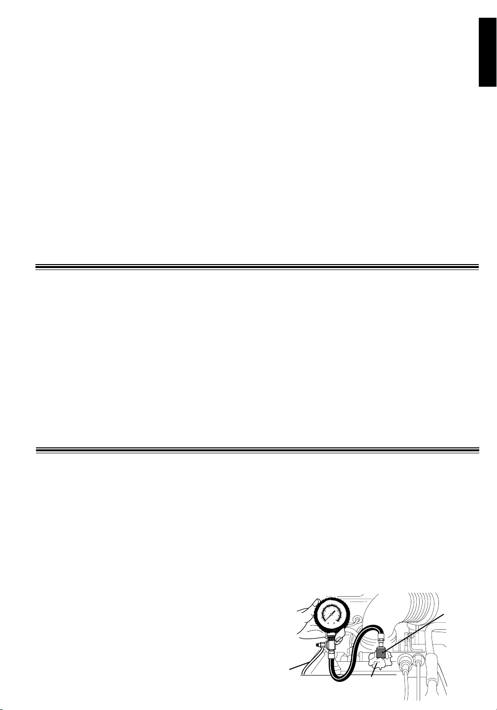
For GM TBI vehicles without a test port ...
Disable fuel pump(s) and relieve fuel system
pressure by following instructions in vehicle
service manual.
WARNING:
Some vehicles may have more than
one fuel pump.
Failure to deactivate all fuel pumps
can result in spilled fuel, fire, or
other hazardous conditions that
could cause vehicle damage
personal injury, or death.
Disconnect the fuel line at location described
in vehicle service manual using shop towels to
catch any released fuel.
Attach GM TBI test adapter, and then attach
fuel line to adapter. Tighten all fittings finger
tight and then tighten gently 1/2 turn with
wrenches.
Attach hose and pressure gauge assembly to
adapter top fitting and tighten fitting until finger
tight.
Pressure
Relief
Button
Pressure
Relief
Button
Fuel Line
from tank
Bleed-Off Hose
40
300
200
20
100
kPa
psi
50
40
60
30
300
400
200
500
20
100
600
700
10
kPa
100
psi
GM TBI Adapter
END OF BLEED OFF HOSE MUST
BE PLACED IN AN APPROVED
40
60
400
500
80
600
700
100
70
80
90
FUEL CONTAINER
GM/Chrysler
Test Port
Adapter
Ford Test
Port Adapter
Fuel Test
Port
Fuel Line
to Engine
Fuel Filter
Shop Towel
For import and some domestic vehicles
with a banjo bolt connection...
Note: The most popular banjo bolt with 12 mm
x 1.25 thread is included, other bolts are
available: Part numbers 0180-1296, 12 mm x
1.5 thread, and 0180-1297, 8 mm x 1.0 thread.
Relieve fuel system pressure by following
instructions in vehicle service manual.
Remove the vehicles fuel bolt at location
described in service manual. Use shop
towels to catch any released fuel.
Install banjo bolt test adapter in place of fuel
bolt. Position banjo bolt gaskets on either
side of banjo. Banjo with fuel supply line
attached should be sandwiched between
banjo bolt gaskets.
Tighten banjo bolt test adapter finger tight,
then gently snug with wrench.
Connect hose and pressure gauge assembly
to banjo bolt test adapter fitting. Tighten
gauge hose fitting finger tight.
40
60
300
400
200
500
20
80
100
600
700
kPa
100
psi
Banjo Bolt Adapter
Page 5

For import and domestic vehicles with
rubber hose connections...
Relieve fuel system pressure by following
instructions in vehicle service manual.
Disconnect the vehicles rubber fuel line hose
at location described in service manual. Use
shop towels to catch any released fuel.
Leave rubber hose attached to fuel line.
Install matching size adapter hose and hose
clamps on dual manifold test adapter.
Connect test adapter hose at location where
vehicles fuel line was disconnected.
Connect vehicles fuel line to other side of
dual manifold adapter. Use vehicles hose
clamps on rubber hose.
Tighten all hose clamps securely.
Connect hose and pressure gauge assembly
to dual manifold test fitting. Tighten gauge
hose fitting finger tight.
5. Place end of 6 foot bleed-off hose in an
approved container for fuel.
Bleed-off hose must remain in container until
testing is complete.
6. Turn all accessories OFF. (Radio, A/C, Blower
Fan, Headlights, Windshield Wipers...)
7. Re-activate fuel pump and turn ignition key ON.
Do the following checks:
Listen for fuel pump. Pump should run for
approximately 2 seconds.
Pressurize fuel system by cycling ignition ON
and OFF every ten seconds until fuel pressure
is at manufacturers specifications (check
vehicle service manual for your particular
application.)
Check fuel system for leaks. If leaks are
found, turn ignition key OFF and wipe up fuel
immediately!
Read fuel pressure from dial face. Pressure
should rise to manufacturers specification and
hold steady.
If fuel pressure is not within manufacturers
specification, cycle ignition key 2 or 3 more
times. If fuel pressure is still not within
manufacturers specifications, service vehicle
according to vehicle service manual, then re-
test.
When key-on-engine-off fuel pressure is within
manufacturers specification, proceed to Step
8.
To safely disconnect Fuel Pressure Test Kit,
proceed to Step 9.
8. Start engine Let idle.
If vehicles fuel system uses a vacuum
actuated (compensated) fuel pressure
regulator then fuel pressure should drop
approximately 3-10 psi, depending on manifold
vacuum.
40
60
300
400
200
500
80
20
100
600
700
kPa
100
psi
Fuel Line
from tank
Dual Manifold Test
Adapter
Fuel Filter
If vehicles fuel system uses a fuel pressure
regulator without a vacuum port then fuel
pressure should remain constant during both
key-on-engine-off and idle.
Read fuel pressure from dial face.
If fuel pressure is not within manufacturers
specification, service vehicle according to
vehicle service manual.
When repair is completed and idle fuel
pressure is now within manufacturers
specification, then proceed to Step 9.
9.Turn Ignition Key OFF.
10.Verify that 6 ft. bleed-off hose is still in an
approved container for fuel.
11.Fully DEPRESS and HOLD the pressure relief
button until dial face pointer is resting on stop
pin.
12.Shake bleed-off hose to make sure that all fuel
went into approved container.
13.Remove gauge hose.
For GM/Chrysler Vehicles with test port...
Wrap a shop rag around fuel rail test port in
case a small amount of fuel drips out while
unscrewing test port adapters.
Unscrew GM/Chrysler test port adapter from
fuel rail test port and reinstall the Test Cap.
Wrap a shop rag around GM/Chrysler test port
adapter so any fuel dripping from gauge hose
is absorbed.
Remove bleed-off hose from approved fuel
container and hold gauge hose over container
so any remaining fuel will drip into container.
For Ford/Lincoln/Mercury vehicles with test
port...
Wrap a shop rag around fuel rail test port in
case a small amount of fuel drips out while
unscrewing test port adapters.
Unscrew GM/Chrysler test port adapter from
Ford test port adapter.
Wrap a shop rag around GM/Chrysler test port
adapter so any fuel dripping from gauge hose
is absorbed.
Remove bleed-off hose from approved fuel
container and hold gauge hose over container
so any remaining fuel will drip into container.
Unscrew Ford test port adapter from fuel rail
test port and reinstall the Test Cap.
English
Page 6

For GM TBI vehicles without a test port ...
English
Place shop rag under GM TBI adapter in case
a small amount of fuel drips out while
unscrewing.
Disconnect Gauge Hose and wrap a shop rag
around so any fuel dripping from hose is
absorbed.
Disconnect fuel lines from GM TBI adapter
and wrap with shop rag so any fuel dripping
from adapter is absorbed.
Reconnect fuel lines as described in vehicle
service manual.
For import and some domestic vehicles
with a banjo bolt connection...
Wrap a shop towel around banjo bolt
connection while removing bolt.
Disconnect hose and pressure gauge
assembly from banjo bolt test adapter.
Wrap a shop towel around end of gauge hose.
Hold end of gauge hose over approved
container to catch any remaining fuel.
Loosen banjo bolt test adapter and remove
adapter and gaskets.
Re-install vehicles fuel bolt with new gaskets
on either side of banjo. Install fuel bolt finger
tight, then wrench-tighten to specifications
given in service manual.
Check for leaks.
For import and domestic vehicles with
rubber hose connections...
Place a shop towel under dual manifold test
adapter.
Disconnect hose and pressure gauge
assembly from dual manifold adapter.
Wrap a shop towel around end of gauge hose.
Hold end of gauge hose over approved
container to catch any remaining fuel.
Loosen hose clamp securing vehicles rubber
fuel line to dual manifold adapter. Disconnect
fuel line from adapter.
Loosen hose clamp securing dual manifold
adapter hose to vehicle. Disconnect adapter
from vehicle.
Reconnect vehicles rubber fuel line to original
location.
Securely tighten hose clamps on vehicles
fuel line.
Check for leaks.
14. Store shop rags in an approved container so they
cannot cause personal injury or a hazardous
situation.
15.Store Fuel Pressure Tester in a well ventilated
area where it cannot cause personal injury or a
hazardous situation.
General Fuel Pressure Diagnostics
Fuel pressure checking is an essential part of fuel injection system troubleshooting. High fuel
pressure will make an engine run rich, while low fuel pressure will make an engine run lean or not at all.
Fuel pressure readings that are higher than manufacturers specifications are generally caused by
a problem in the fuel return line components. Conversely, fuel pressure readings that are lower than
manufacturers specifications are generally caused by a problem in the fuel pressure line components.
If fuel pressure readings are not within manufacturers specifications, then refer to a vehicle service
manual for step-by-step diagnostic procedures that will pinpoint the faulty component for a specific vehicle.
Possible causes of high fuel pressure
readings are the following:
Faulty fuel pressure regulator
Restriction in return line
Faulty fuel line couplings at fuel tank
Sticking or Sluggish Fuel Injectors
Possible causes of low fuel pressure readings
are the following:
Clogged or restricted fuel filter
Restriction in pressure line
Faulty fuel pump
Faulty fuel pump relay
Blown fuel pump fuse
Faulty fuel pump wiring
Clogged or restricted fuel pump filter
Faulty fuel pressure regulator
Leaking fuel injectors
Faulty fuel line couplings at fuel tank.
Care and Maintenance
Apply a lightweight household oil to the rubber O rings inside adapters before each use.
Page 7

Vehicle Service Information:
The following is a list of publishers who have manuals containing electronic fuel injection system
information. Some manuals may be available at auto parts stores, local dealers, or local public libraries.
For others, write for availability and prices, specifying make, model and year of vehicle.
English
Aftermarket Vehicle Service Manuals:
Chilton Book Company
Chilton Way
Radnor, PA 19089
Haynes Publications
861 Lawrence Drive
Newbury Park, CA 91320
Cordura Publications
Mitchell Manuals, Inc.
Post Office Box 26260
San Diego, CA 92126
Motors Auto Repair Manual
Hearst Company
250 W. 55th Street
New York, NY 10019
Vehicle Service Manuals from
Ford Motor Company:
Ford Publication Department
Helm Incorporated
Post Office Box 07150
Detroit, MI 48207
Vehicle Service Manuals from
General Motors Corporation:
Buick
Tuar Company
Post Office Box 354
Flint, MI 48501
Oldsmobile
Lansing Lithographers
Post Office Box 23188
Lansing, MI 48909
Cadillac, Chevrolet, Pontiac
Helm Incorporated
Post Office Box 07130
Detroit, MI 48207
Vehicle Service Manuals from
Chrysler Corporation:
Chrysler Corporation
Dyment Distribution Service
Service Publication
12200 Alameda Drive
Strongsville, Ohio 44136
Customer Service
For product information or customer service please call 1-800-ACTRON-7 (1-800-228-7667) or fax
anytime at (216) 898-1636.
Actron can also be reached by Email or on the Internet.
Email address: sunpro@actron.com
Internet home page: http://www.actron.com
One Year Warranty
If within one year from the date of purchase this equipment fails due to defect in materials or
workmanship, return it to ActronTM and ActronTM will repair it free of charge.
This warranty gives you specific legal rights, and you may also have other rights which may vary
from state to state.
All information, illustrations and specifications contained in this manual are based on the latest
information available from industry sources at the time of publication. No warranty (expressed or
implied) can be made for its accuracy or completeness, nor is any responsibility assumed by Actron
Manufacturing Co. or anyone connected with it for loss or damages suffered through reliance on any
information contained in this manual or misuse of accompanying product. ActronTM Manufacturing Co.
reserves the right to make changes at any time to this manual or accompanying product without
obligation to notify any person or organization of such changes.
TM
Page 8

Servicio al Cliente
Para obtener información del producto o servicio al cliente, por favor llame al teléfono 1-800-ACTRON7 (1-800-228-7667) (para EUA) o envíe un fax en cualquier momento al telefax (216) 898-1636 (para
EUA).
También puede comunicarse con Actron a través del correo electrónico o el sitio de Internet.
Dirección de correo electrónico: sunpro@actron.com
Página principal de Internet: http://www.actron.com
Garantía de 1 Año (Para Garant ía en Mexico consultor con Vendedor)
Si dentro de un período de un (1) año a partir de la fecha de compra este juego presenta falla debido a
defecto en el material o fabricación, devuélvalo a ActronTM y ActronTM lo reparará sin costo.
Esta garantía le otorga derechos legales específicos, y también podría tener otros derechos que
pueden variar de estado a estado.
Toda la información, ilustraciones y especificaciones contenidas en este manual están basadas en la
información más reciente disponible de fuentes industriales en el momento de la publicación. No
puede suministrarse garantía (expresa o implícita) en cuanto a su exactitud o integridad, ni Actron
Manufacturing Co. ni nadie relacionado con ActronTM asume ninguna responsabilidad por pérdida o
daños sufridos por depositar su confianza en cualquier información contenida en este manual o por
maltrato del producto acompañante. ActronTM Manufacturing Co. se reserva del derecho de hacer
cambios en cualquier momento a este manual o el producto acompañante sin obligación de notificar a
ninguna persona u organización acerca de dichos cambios.
TM
Made in China
Fabriqué en China
Hecho en China
© 2004 ActronTM Manufacturing Company. All Rights Reserved.
© 2004 ActronTM Manufacturing Company. Tous Droits Réservés.
© 2004 ActronTM Manufacturing Company. Todos Los Derechos Reservados.
0002-001-2612
 Loading...