


AcceleRAID™ 352 PCI to Ultra 160 SCSI RAID Controller Installation Guide
Part Number 775051-01
08P4089
© Copyright 2000 Mylex Corporation.
All Rights Reserved.
All contents of this manual are copyrighted by Mylex Corporation. The information contained herein is the exclusive property of Mylex Corporation and shall not be copied, transferred, photocopied, translated on paper, film, electronic media, or computer-readable form; or otherwise reproduced in any way, without the express written permission of Mylex Corporation.
Greetings
Thank you for purchasing the Mylex AcceleRAID™ 352 disk array controller. Requests for technical information about this and other Mylex Corporation products should be made to your Mylex authorized reseller or Mylex marketing representative.
Please Notice
IBM, Mylex, AcceleRAID, RAID EzAssist, Global Array Manager, and GAM are trademarks or registered trademarks of International Business Machines Corp. and its subsidiaries. Microsoft, MS-DOS, Windows 95, Windows 98, Windows NT, and Windows 2000 are registered trademarks of Microsoft Corporation. Novell and NetWare are a registered trademarks of Novell Corporation. SCO and UnixWare are registered trademarks of Santa Cruz Operations. Other names that are trademarks may be used herein for the purpose of identifying the products or services of their respective owners.
Unless otherwise noted, companies, names and data used in examples herein are fictitious.
Our Policy
Although reasonable efforts have been made to assure the accuracy of the information contained herein, this publication could include technical inaccuracies or typographical errors. Mylex Corporation expressly disclaims liability for any error in this information, and for damages, whether direct, indirect, special, exemplary, consequential or otherwise, that may result from such error, including but not limited to loss of profits resulting from the use or misuse of the manual or information contained therein (even if Mylex Corporation has been advised of the possibility of such damages). Any questions or comments regarding this document or its contents should be addressed to Mylex Corporation at the address shown on the back cover.
The following paragraph does not apply to the United Kingdom or any country where such provisions are inconsistent with local law:
MYLEX CORPORATION PROVIDES THIS PUBLICATION “AS IS” WITHOUT WARRANTY OF ANY KIND, EITHER EXPRESS OR IMPLIED, INCLUDING, BUT NOT LIMITED TO, THE IMPLIED WARRANTIES OF MERCHANTABILITY OR FITNESS FOR A PARTICULAR PURPOSE.
Some states do not allow disclaimer of express or implied warranties or the limitation or exclusion of liability for indirect, special, exemplary, incidental or consequential damages in certain transactions; therefore, this statement may not apply to you. Also, you may have other rights which vary from jurisdiction to jurisdiction.
Information in this publication is subject to change without notice and does not represent a commitment on the part of Mylex Corporation. Changes may be made periodically to the information herein; these changes will be incorporated in new editions of the publication. Mylex Corporation reserves the right to make improvements and/or changes at any time in the product(s) and/or program(s) described in this publication.
It is possible that this publication may contain reference to, or information about, Mylex Corporation products (machines and programs), programming or services that are not announced in your country. Such references or information must not be construed to mean that Mylex Corporation intends to announce, provide, or make available such Mylex products, programming, or services in your jurisdiction.
About This Manual
This installation guide covers hardware set-up and configuration procedures necessary for the installation of a Mylex AcceleRAID 352 dual channel RAID controller.
Chapter 1 describes the controller, standard package contents, and usersupplied items necessary for installation.
Chapter 2 describes the steps to be performed prior to controller installation and the physical installation of the AcceleRAID 352 dual channel RAID controller.
Chapter 3 describes controller start-up and the BIOS options.
Appendix A describes the memory and battery backup module.
Appendix B provides hardware and environmental specifications.
Appendix C describes error messages and problem correction.
Appendix D describes the PCI Hot Plug feature.
Appendix E provides enclosure management information.
Appendix F provides regulatory agency information.
Conventions
Throughout the manual, the following conventions are used to describe user interaction with the product:
prompt This style of type indicates screen display messages
Enter Press the key labeled “Enter” (or “Delete,” etc.)
Note
Supplementary information that can have an effect on system performance.
Caution
Notification that a proscribed action has the potential to adversely affect equipment operation, system performance, or data integrity.
WARNING
Notification that a proscribed action will definitely result in equipment damage, data loss, or personal injury.

Contents
Chapter 1
Introduction
Product Description ........................................................................... |
1-1 |
Controller Features .................................................................... |
1-2 |
Channel Capabilities .................................................................. |
1-2 |
Controller Capabilities ................................................................ |
1-2 |
Operating System Support ......................................................... |
1-3 |
Standard Package Contents ............................................................. |
1-4 |
Hardware .................................................................................... |
1-4 |
Software ..................................................................................... |
1-4 |
User-supplied Items .......................................................................... |
1-5 |
Chapter 2 |
|
Installation |
|
Before You Begin .............................................................................. |
2-2 |
Safety Considerations ....................................................................... |
2-3 |
Installation Checklist .......................................................................... |
2-4 |
GET READY .............................................................................. |
2-4 |
GET SET .................................................................................... |
2-4 |
GO .............................................................................................. |
2-4 |
Connectors, Jumpers and LEDs ........................................................ |
2-5 |
PCI Hotplug ................................................................................ |
2-5 |
Installation Process ........................................................................... |
2-9 |
Installing the Controller .............................................................. |
2-9 |
Preparing the SCSI Drives ....................................................... |
2-11 |
SCSI Termination ..................................................................... |
2-13 |
SCSI Cabling ................................................................................... |
2-17 |
LVD Mode ................................................................................ |
2-17 |
Single-ended Mode .................................................................. |
2-17 |
Limitations on Mixing SCSI Drives .................................................. |
2-18 |
Do Not Mix Narrow and Wide SCSI Drives .............................. |
2-18 |
Mixing LVD with Single-ended Drives ...................................... |
2-18 |
Manual No. 775051 |
v |

Chapter 3
Controller Start-up
BIOS Options ..................................................................................... |
3-1 |
Setting BIOS Options ................................................................. |
3-2 |
BIOS Configuration Utility (RAID EzAssist) ....................................... |
3-4 |
Operating System .............................................................................. |
3-4 |
Operating System Device Drivers ...................................................... |
3-4 |
Global Array Manager (GAM) Server ................................................ |
3-4 |
Global Array Manager (GAM) Client .................................................. |
3-5 |
In Case of Problems .......................................................................... |
3-5 |
Appendix A |
|
BBM-Battery Backup Module |
|
Product Description ........................................................................... |
A-1 |
Features ..................................................................................... |
A-1 |
BBM Operation .................................................................................. |
A-2 |
Set-up – Enabling the Write-Back Cache ................................... |
A-2 |
Battery Backup Capacity ............................................................ |
A-2 |
Maintenance ...................................................................................... |
A-3 |
Removing the BBM .................................................................... |
A-3 |
BBM Functional Description .............................................................. |
A-3 |
Status Indication ......................................................................... |
A-4 |
Battery and Charge Circuit ......................................................... |
A-4 |
Disposition of Failed Batteries .................................................... |
A-4 |
BBM Specifications ............................................................................ |
A-5 |
On-board Battery ........................................................................ |
A-5 |
Battery Charge Life (Data Retention) ......................................... |
A-5 |
Module Dimensions .................................................................... |
A-5 |
Environmental ............................................................................ |
A-5 |
Warranty ..................................................................................... |
A-5 |
Appendix B |
|
AcceleRAID 352 Specifications |
|
General Hardware Specifications ...................................................... |
B-1 |
AcceleRAID 352 ......................................................................... |
B-1 |
Appendix C |
|
AcceleRAID 352 Error Messages |
|
Start-up Error Messages ................................................................... |
C-1 |
Drive Check Error Messages ............................................................ |
C-1 |
Installation Abort ............................................................................... |
C-2 |
System Reboot or Power Down ........................................................ |
C-3 |
vi |
AcceleRAID 352 Installation Guide |

Appendix D
PCI Hot Plug
Introduction ........................................................................................ |
D-1 |
Implementation .................................................................................. |
D-1 |
NetWare ..................................................................................... |
D-1 |
Windows NT ............................................................................... |
D-3 |
Windows 2000 ............................................................................ |
D-3 |
Windows 64 ................................................................................ |
D-4 |
Appendix E |
|
Enclosure Management |
|
Introduction ........................................................................................ |
E-1 |
SAF-TE .............................................................................................. |
E-1 |
SES ................................................................................................... |
E-2 |
Appendix F |
|
Regulatory Information |
|
Class B Compliance .......................................................................... |
F-1 |
Declaration of Conformity .................................................................. |
F-2 |
Declaration of Conformity .................................................................. |
F-3 |
Community of Europe ........................................................................ |
F-4 |
Underwriters Laboratories Statement and Warning .......................... |
F-5 |
Glossary
Manual No. 775051 |
vii |

viii |
AcceleRAID 352 Installation Guide |
Chapter 1
Introduction
This chapter describes:
•The AcceleRAID™ 352 controller
•Standard package contents
•User supplied items
Figure 1-1. AcceleRAID 352 Controller
Product Description
The Mylex AcceleRAID 352 controller is an Ultra 160 SCSI to a PCI dual channel RAID controller with 64-bit, 33MHz PCI capability. The AcceleRAID 352 supports two external Ultra 160 SCSI connectors, two internal Ultra 160 SCSI connectors, and an optional battery backup module (BBM). The AcceleRAID 352 controller provides the speed and functionality required by high demand server platforms. AcceleRAID 352 achieves performance breakthroughs in PCI technology, eliminates storage bottlenecks and delivers scalable performance. Enclosure management and PCI Hot Plug are standard features.
Manual No. 775051 |
1-1 |

Product Description
Controller Features
Features of the AcceleRAID 352 controller include:
•One Q-Logic ISP 12160A chip to support two Ultra 160 SCSI LVD channels
•Intel i960RN at 100MHz RISC processor
•BBM (Battery Backup Module), optional
•32MB, 64MB, or 128MB ECC cache DIMM module
•PCI 2.1 and 2.2 compliant (PCI 2.2 required to use hotplug feature)
•1MB, 8-bit flash EEPROM for BIOS and code
•Built-in configuration utilities (in BIOS)
•Write-through and write-back cache support.
•PCI Hotplug capability allows the AcceleRAID 352 to be swapped with a replacement without powering down the system.
Caution
Be sure the motherboard you are using supports PCI Hotplug before attempting to use this feature, or serious damage to the controller and/or the motherboard could result. (You must be PCI 2.2 compliant if using PCI Hot Plug.)
Channel Capabilities
• 15 Ultra 160 SCSI devices per channel
Controller Capabilities
•16 physical drives per drive group (array)
•Number of drive groups is limited by number of physical drives on the controller
•32 total logical drives per controller
•Supports RAID levels 0, 1, 0+1, 3, 5, 10, 30, 50, and JBOD
1-2 |
AcceleRAID 352 Installation Guide |

Introduction
Operating System Support
MS-DOS 5.x, 6.x, and above are supported using drivers that reside in the AcceleRAID BIOS. Many other popular operating systems are supported using software drivers in the Disk Array Controller Software Kit that is included with the AcceleRAID 352 controller (see the PCI Disk Array Controller Drivers Installation Guide and User Manual).
Manual No. 775051 |
1-3 |
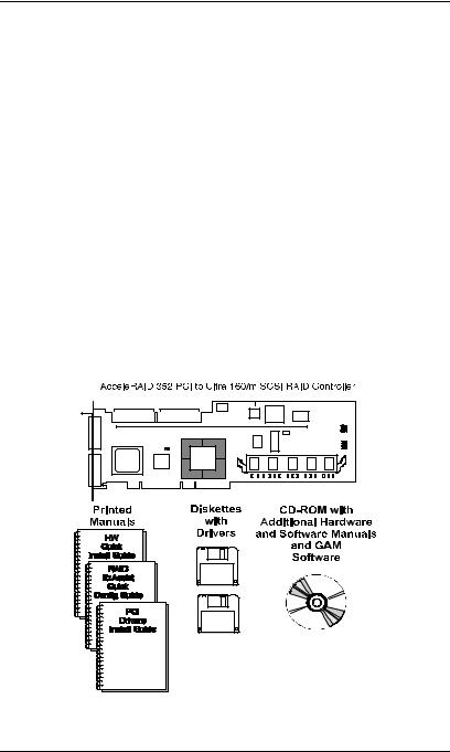
Standard Package Contents
Standard Package Contents
The following items are supplied with the standard shipping package:
Hardware
•AcceleRAID 352 Disk Array Controller with documentation included on the CD-ROM and a printed Quick Installation Guide.
•Standard DIMM Memory Module: 32MB, 64MB, or 128MB with an
optional battery backup (BBM) pre-installed, OR
• Standard DIMM Module only: 32MB, 64MB, or 128MB
Software
•RAID EzAssist disk array controller configuration utility with documentation on CD-ROM and a printed Quick Configuration Guide.
•Software Kit Driver with documentation on CD-ROM and a printed PCI Drivers Installation guide
•Global Array Manager (GAM) with documentation on CD-ROM
Figure 1-2. Standard Package Contents
1-4 |
AcceleRAID 352 Installation Guide |

Introduction
User-supplied Items
The following user-supplied items are required to perform this installation:
•IBM-PC™ compatible host system with PCI slot (PCI 2.1 and 2.2 compliant; you must be PCI 2.2 compliant to use PCI Hot Plug)
•Network operating system software (as required)
•SCSI cables to connect the controller and disk arrays
•Static grounding strap or electrostatic discharge (ESD) safe work area
•Disk array enclosure (or equivalent) with SCSI disk drives
Manual No. 775051 |
1-5 |

User-supplied Items
1-6 |
AcceleRAID 352 Installation Guide |

Chapter 2
Installation
This chapter describes:
•Before you begin
•Safety considerations
•Installation checklist
•Connectors, Jumpers, LED’s
•Controller installation
•SCSI cabling and termination
•SCSI IDs
•Limitations on mixing SCSI drive types
Mylex disk array controllers are designed to work in a variety of SCSI RAID application environments. Certain configuration steps need to be performed prior to installing the controller into a RAID environment. Each of the steps described in this chapter are part of the installation process.
Manual No. 775051 |
2-1 |

Before You Begin
Before You Begin
Installing the AcceleRAID 352 Dual Channel RAID controller is no more difficult than installing any 32-bit or 64-bit PCI adapter. The AcceleRAID 352 dual channel controller connects into any PCI slot (PCI 2.1 or 2.2 compliant) on the motherboard. Follow these steps and the installation procedures in this chapter.
WARNING
Working with the system covers off and power applied to the system can result in shock and serious injury.
This controller is furnished with a nonvolatile RAM (NVRAM) chip that uses a sealed lithium battery/crystal module. Replace the module only with the same or equivalent type recommended by the manufacturer.
Dispose of the used battery/crystal module according to the manufacturer’s instructions. Never incinerate a battery as it could explode and cause serious injury.
1.Power off the system and disconnect the power cables before starting the installation. Refer to the instructions provided in your system documentation. Do not disconnect cables or power cords while system power is on.
2.Read all of the instructions in this chapter completely before proceeding. Follow the Notes, Cautions, and Warnings described in this manual and marked on the equipment.
3.Follow electrostatic discharge (ESD) safe procedures. Use a grounded wrist strap or ESD safe footwear, and work in an ESD safe area.
4.Perform a safety check of the installation before powering on the system.
•Make sure that the cabling Pin 1 location is correct and that all cables are firmly seated in the connectors.
•Make sure all SCSI conventions (cable type, cable length, termination, etc.) are correct, see Table 2-5.
2-2 |
AcceleRAID 352 Installation Guide |

Installation
Safety Considerations
Be sure to observe the following precautions before beginning the controller installation procedure:
Caution
Anti-static handling procedures are required. Leave the controller in its anti-static bag until it is time to plug the controller into the PCI slot. The use of a grounded wrist strap and other ESD protective measures are highly recommended.
WARNING
Disconnect the system from the electrical wall outlet before opening the system cabinet. Working with the system covers off and power applied to the system can result in shock and serious injury.
Manual No. 775051 |
2-3 |

Installation Checklist
Installation Checklist
GET READY
Note
It is recommended that you wear a grounded wrist strap when working with hardware installation procedures.
1.____ Power off your computer system.
2.____ Decide which available PCI slot will be used.
3.____ Remove the plate from the I/O access port to the PCI slot.
4.____ Remove the AcceleRAID 352 controller from the anti-static bag.
GET SET
5.____ Plug the AcceleRAID 352 controller into a standard PCI slot (PCI 2.1 or 2.2 compliant--if using hotplug feature, must be 2.2).
6.____ Tighten the AcceleRAID 352 controller into the mounting bracket.
7.____ Connect the SCSI cable(s) from your drive(s) and/or device(s) to the desired SCSI channel.
8.____ Check SCSI termination for internal and/or external devices.
9.____ Check disk drives. Be sure termination is set to the disabled position on any disk drive(s) that will not be terminated. For more information, see the documentation that accompanied the disk drives.
10.____ Set SCSI ID on the disk drive(s).
11.____ Enable termination power on disk drive(s).
12.____ Safety check the installation.
Note
Review Figure 2-1 and Table 2-5 to get familiar with the layout of the AcceleRAID 352 controller and the Connectors, Jumpers, and LED descriptions.
GO
13. ____ Go to Chapter 3, Controller Start-up.
2-4 |
AcceleRAID 352 Installation Guide |
Installation
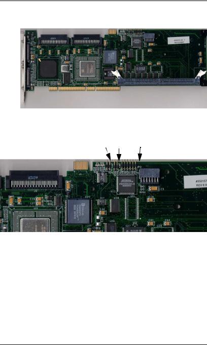
Connectors, Jumpers and LEDs
There are two external Ultra 160 SCSI channels (connectors) supported on the controller as shown in Figure 2-1.
SCSI jumpers should normally be set to their default settings, no adjustments are needed. Default jumper locations are shown in Figure 2-2 and are described in Table 2-1.
The AcceleRAID 352 controller has one LED on the front side as shown in Figure 2-3 and described in Table 2-2.
There are four LEDs on the back of the controller that are mode indicators while the controller is running, shown in Figure 2-4 and described in Table 2-3.
The LEDs indicate single ended, LVD, and FAIL modes.
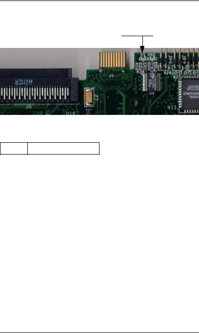
In addition there is a six-pin header. Figure 2-4 identifies the location of each pin. Table 2-4 identifies the function of each pin: 3.3V power, Channel 0 and Channel 1 SCSI activity, cache dirty status and, a ground pin.
When you have checked the termination requirements, completed the connections of your desired SCSI devices and other possible devices such as a CD-ROM drive or a tape drive, close your system with the cover.
PCI Hotplug
Note
Please see Appendix D for information on how to implement the Hotplug feature for your system’s requirements.
Manual No. 775051 |
2-5 |
Connectors, Jumpers and LEDs
CH0 CH1
CH0
CH1
Figure 2-1. AcceleRAID 352 Controller with Connectors
JP1 JP2 JP3
Figure 2-2. AcceleRAID 352 Default Jumper Identification
Table 2-1. AcceleRAID 352 Default Jumper Descriptions
JP1 |
Blank ROM mode |
|
|
JP2 |
Maintenance mode |
|
|
JP3 |
6-pin header |
|
|
2-6 |
AcceleRAID 352 Installation Guide |
Installation
FAIL LED
U1
Figure 2-3. AcceleRAID 352 Controller with LED (front)
Table 2-2. LED Description (front)
U1 FAIL LED
Manual No. 775051 |
2-7 |

Connectors, Jumpers and LEDs
SE 1 SE 0 LVD 0 LVD 1 |
PIN Nos. |
|
|
|
6 5 4 3 2 1 |
|
|
|
|
|
|
Figure 2-4. AcceleRAID 352 Controller with LEDs and Pin Numbers (back)
|
Table 2-3. LED Descriptions (back) |
||||
|
|
|
|
|
|
SE 1 |
|
|
Single-ended LED, Channel 1 |
||
|
|
|
|
|
|
SE 0 |
|
|
Single-ended LED, Channel 0 |
||
|
|
|
|
|
|
LVD 0 |
|
|
LVD LED, Channel 0 |
||
|
|
|
|
|
|
LVD 1 |
|
|
LVD LED, Channel 1 |
||
|
|
|
|
||
Table 2-4. Six-Pin Header Identification (JP3) |
|||||
|
|
|
|
|
|
Pin 1 |
|
|
3.3V power |
|
|
|
|
|
|
|
|
Pin 2 |
|
|
Channel |
0 SCSI activity |
|
|
|
|
|
|
|
Pin 3 |
|
|
Channel |
1 SCSI activity |
|
|
|
|
|
|
|
Pin 4 |
|
|
Not used, not connected |
|
|
|
|
|
|
|
|
Pin 5 |
|
|
Cache Dirty and SCSI activity |
|
|
|
|
|
|
|
|
Pin 6 |
|
|
Ground pin |
|
|
|
|
|
|
|
|
2-8 |
AcceleRAID 352 Installation Guide |

Installation
Installation Process
Installing the Controller
Follow these installation steps:
1. Choose any available 32-bit or 64-bit PCI slot as shown in Figure 2-5.
Figure 2-5. Choose an Available PCI Slot
2.Remove the metal cover plate from the slot’s access port (usually at the back of the cabinet) by releasing the black clip as illustrated below shown in Figure 2-6.
Figure 2-6. Remove the Metal Plate
Manual No. 775051 |
2-9 |
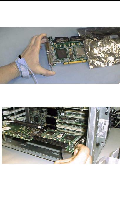
Installation Process
3.Remove the AcceleRAID 352 controller from the anti-static bag as shown in Figure 2-7. Always handle the controller by the edges and wear a ground wrist strap.
Ground
Wrist Strap
Figure 2-7. Remove the controller from the Anti-static Bag
4.Plug (install) the controller firmly into any 32-bit or 64-bit PCI slot as shown in Figure 2-8.
Figure 2-8. Plug the Controller into any 32-bit or 64-bit PCI Slot
2-10 |
AcceleRAID 352 Installation Guide |

Installation
Preparing the SCSI Drives
To prepare the drives for installation, follow these steps:
•Remove any terminators attached to the drive or set any drive termination jumpers to the disabled position.
•Set the SCSI IDs on the drives.
•Enable term power on the drives.
Refer to the drive manual for specific information about drive configuration settings.
Installing Cables and Setting Termination
Please refer to Table 2-5 for SCSI Formats and Bus Length requirements.
5.Connect the SCSI cables from the internal disk drives to the SCSI connector(s) on the AcceleRAID 352 controller, as shown in
Figure 2-9. (The controller is already connected to the system board.)
Figure 2-9. Connecting Disk Drives to the AcceleRAID 352
Manual No. 775051 |
2-11 |

Installation Process
Note
In order to ensure an error free environment, the proper cable type designed for a certain SCSI
speed must be used, please refer to Table 2-5 on page 2-17.
Note
It is recommended that non-RAID SCSI devices be connected to a separate SCSI channel, either on the system board or furnished by a SCSI host bus adapter.
Note
To avoid problems caused by mixing drive types, please refer to “Limitations on Mixing SCSI Drives” on page 2-18.
2-12 |
AcceleRAID 352 Installation Guide |
 Loading...