


 TX-8011_E.book Page1 Friday, July30, 2004 10:33 AM
Stereo Receiver
TX-8011
Instruction Manual
Thank you for purchasing an Onkyo Stereo Receiver. Please read this manual thoroughly before making connections and plugging in the unit.
Following the instructions in this manual will enable you to obtain optimum performance and listening enjoyment from your new Stereo Receiver.
Please retain this manual for future reference.
Contents
Introduction ..................................... |
2 |
Connection .................................... |
11 |
Playing Your Components ........... |
17 |
Using the Tuner ............................. |
19 |
Recording ...................................... |
21 |
Troubleshooting ............................ |
22 |
Specifications................................ |
23 |
En

 TX-8011_E.book Page2 Friday, July30, 2004 10:33 AM
WARNING:
TO REDUCE THE RISK OF FIRE OR ELECTRIC SHOCK, DO NOT EXPOSE THIS APPLIANCE TO RAIN OR MOISTURE.
CAUTION:
TO REDUCE THE RISK OF ELECTRIC SHOCK, DO NOT REMOVE COVER (OR BACK). NO USER-SERVICEABLE PARTS INSIDE. REFER SERVICING TO QUALIFIED SERVICE PERSONNEL.
WARNING |
|
AVIS |
RISK OF ELECTRIC SHOCK |
|
RISQUE DE CHOC ELECTRIQUE |
DO NOT OPEN |
|
NE PAS OUVRIR |
|
|
|
The lightning flash with arrowhead symbol, within an equilateral triangle, is intended to alert the user to the presence of uninsulated “dangerous voltage” within the product’s enclosure that may be of sufficient magnitude to constitute a risk of electric shock to persons.
The exclamation point within an equilateral triangle is intended to alert the user to the presence of important operating and maintenance (servicing) instructions in the literature accompanying the appliance.
Important Safeguards
1.Read Instructions—All the safety and operating instructions should be read before the appliance is operated.
2.Retain Instructions—The safety and operating instructions should be retained for future reference.
3.Heed Warnings—All warnings on the appliance and in the operating instructions should be adhered to.
4.Follow Instructions—All operating and use instructions should be followed.
5.Cleaning—Unplug the appliance from the wall outlet before cleaning. The appliance should be cleaned only as recommended by the manufacturer.
6.Attachments—Do not use attachments not recommended by the appliance manufacturer as they may cause hazards.
7.Water and Moisture—Do not use the appliance near water –for example, near a bath tub, wash bowl, kitchen sink, or laundry tub; in a wet basement; or near a swimming pool; and the like.
8. Accessories—Do not place the appliance on an unstable
cart, stand, tripod, bracket, or table. The appliance may
fall, causing serious injury
to a child or adult, and seri-
S3125A
ous damage to the appliance. Use only with a cart,
stand, tripod, bracket, or table recommended by the manufacturer, or sold with the appliance. Any mounting of the appliance should follow the manufacturer’s instructions, and should use a mounting accessory recommended by the manufacturer.
9.An appliance and cart combination should be moved with care. Quick stops, excessive force, and uneven surfaces may cause the appliance and cart combination to overturn.
10.Ventilation—Slots and openings in the cabinet are provided for ventilation and to ensure reliable operation of the appliance and to protect it from overheating, and these openings must not be blocked or covered. The openings should never be blocked by placing the appliance on a bed, sofa, rug, or other similar surface. The appliance should not be placed in a built-in installation such as a bookcase or rack unless proper ventilation is provided. There should be free space of at least 8 in. (20 cm) and an opening behind the appliance.
11.Power Sources—The appliance should be operated only from the type of power source indicated on the marking label. If you are not sure of the type of power supply to your home, consult your appliance dealer or local power company.
12.Grounding or Polarization—The appliance may be equipped with a polarized alternating current line plug (a plug having one blade wider than the other). This plug will fit into the power outlet only one way. This is a safety feature. If you are unable to insert the plug fully into the outlet, try reversing the plug. If the plug should still fail to fit, contact your electrician to replace your obsolete outlet. Do not defeat the safety purpose of the polarized plug.
13.Power Cord Protection—Power-supply cords should be routed so that they are not likely to be walked on or pinched by items placed upon or against them, paying particular attention to cords at plugs, convenience receptacles, and the point where they exit from the appliance.
14. Outdoor Antenna Grounding—If an outside antenna or cable system is connected to the appliance, be sure the antenna or cable system is grounded so as to provide some protection against voltage surges and built-up static charges. Article 810 of the National Electrical Code, ANSI/NFPA 70, provides information with regard to proper grounding of the mast and supporting structure, grounding of the leadin wire to an antenna-discharge unit, size of grounding conductors, location of antenna-discharge unit, connection to grounding electrodes, and requirements for the grounding electrode. See Figure 1.
15.Lightning—For added protection for the appliance during a lightning storm, or when it is left unattended and unused for long periods of time, unplug it from the wall outlet and disconnect the antenna or cable system. This will prevent damage to the appliance due to lightning and power-line surges.
16. Power Lines—An outside antenna system should not be located in the vicinity of overhead power lines or other electric light or power circuits, or where it can fall into such power lines or circuits. When installing an outside antenna system, extreme care should be taken to keep from touching such power lines or circuits as contact with them might be fatal.
2

 TX-8011_E.book Page 3 Friday, July 30, 2004 10:33 AM
Important Safeguards—Continued
17.Overloading—Do not overload wall outlets, extension cords, or integral convenience receptacles as this can result in a risk of fire or electric shock.
18.Object and Liquid Entry—Never push objects of any kind into the appliance through openings as they may touch dangerous voltage points or short-out parts that could result in a fire or electric shock. Never spill liquid of any kind on the appliance.
19.Servicing—Do not attempt to service the appliance yourself as opening or removing covers may expose you to dangerous voltage or other hazards. Refer all servicing to qualified service personnel.
20.Damage Requiring Service—Unplug the appliance from the wall outlet and refer servicing to qualified service personnel under the following conditions:
A.When the power-supply cord or plug is damaged,
B.If liquid has been spilled, or objects have fallen into the appliance,
C.If the appliance has been exposed to rain or water,
D.If the appliance does not operate normally by following the operating instructions. Adjust only those controls that are covered by the operating instructions as an improper adjustment of other controls may result in damage and will often require extensive work by a qualified technician to restore the appliance to its normal operation,
E.If the appliance has been dropped or damaged in any way, and
F.When the appliance exhibits a distinct change in performance – this indicates a need for service.
21.Replacement Parts—When replacement parts are required, be sure the service technician has used replacement parts specified by the manufacturer or have the same characteristics as the original part. Unauthorized substitutions may result in fire, electric shock, or other hazards.
22.Safety Check—Upon completion of any service or repairs to the appliance, ask the service technician to perform safety checks to determine that the appliance is in proper operation condition.
23.Wall or Ceiling Mounting—The appliance should be mounted to a wall or ceiling only as recommended by the manufacturer.
24.Heat—The appliance should be situated away from heat sources such as radiators, heat registers, stoves, or other appliances (including amplifiers) that produce heat.
25.Liquid Hazards—The appliance should not be exposed to dripping or splashing and no objects filled with liquids, such as vases should be placed on the appliance.
FIGURE 1:
EXAMPLE OF ANTENNA GROUNDING AS PER NATIONAL ELECTRICAL CODE, ANSI/NFPA 70
ANTENNA
LEAD IN
WIRE
GROUND  CLAMP
CLAMP 
ANTENNA DISCHARGE UNIT (NEC SECTION 810-20)
ELECTRIC
SERVICE
EQUIPMENT
GROUNDING CONDUCTORS (NEC SECTION 810-21)

 GROUND CLAMPS

 POWER SERVICE GROUNDING NEC – NATIONAL ELECTRICAL CODE ELECTRODE SYSTEM
(NEC ART 250, PART H)
S2898A
3

 TX-8011_E.book Page 4 Friday, July 30, 2004 10:33 AM
Precautions
1.Recording Copyright—Unless it’s for personal use only, recording copyrighted material is illegal without the permission of the copyright holder.
2.AC Fuse—The AC fuse inside the TX-8011 Receiver is not user-serviceable. If you cannot turn on the TX-8011 Receiver, contact your Onkyo dealer.
3.Care—Occasionally you should dust the TX-8011 Receiver all over with a soft cloth. For stubborn stains, use a soft cloth dampened with a weak solution of mild detergent and water. Dry the TX-8011 Receiver immediately afterwards with a clean cloth. Don’t use abrasive cloths, thinners, alcohol, or other chemical solvents, because they may damage the finish or remove the panel lettering.
4.Power WARNING
BEFORE PLUGGING IN THE UNIT FOR THE FIRST TIME, READ THE FOLLOWING SECTION CAREFULLY.
AC outlet voltages vary from country to country. Make sure that the voltage in your area meets the voltage requirements printed on the TX-8011 Receiver’s rear panel (e.g., AC 230 V, 50 Hz or AC 120 V, 60 Hz).
Setting the [STANDBY/ON] switch to STANDBY does not fully shutdown the TX-8011 Receiver. If you do not intend to use the TX-8011 Receiver for an extended period, remove the power cord from the AC outlet.
Memory backup
The TX-8011 uses a battery-less memory backup system in order to retain radio presets and other settings when it’s unplugged or in the case of a power failure. Although no batteries are required, the TX-8011 Receiver must be plugged into an AC outlet in order to charge the backup system.
Once it has been charged, the TX-8011 Receiver will retain the settings for several weeks, although this depends on the environment and will be shorter in humid climates.
For U.S. models
Note to CATV system installer:
This reminder is provided to call the CATV system installer's attention to Section 820-40 of the NEC which provides guideline for proper grounding and, in particular, specified that the cable ground shall be connected to the grounding system of the building, as close to the point of cable entry as practical.
FCC Information for User
CAUTION:
The user changes or modifications not expressly approved by the party responsible for compliance could void the user’s authority to operate the equipment.
NOTE:
This equipment has been tested and found to comply with the limits for a Class B digital device, pursuant to Part 15 of the FCC Rules. These limits are designed to provide reasonable protection against harmful interference in a residential installation.
This equipment generates, uses and can radiate radio frequency energy and, if not installed and used in accordance with the instructions, may cause harmful interference to radio communications. However, there is no guarantee that interference will not occur in a particular installation. If this equipment does cause harmful interference to radio or television reception, which can be determined by turning the equipment off and on, the user is encouraged to try to correct the interference by one or more of the following measures:
•Reorient or relocate the receiving antenna.
•Increase the separation between the equipment and receiver.
•Connect the equipment into an outlet on a circuit different from that to which the receiver is connected.
•Consult the dealer or an experienced radio/TV technician for help.
For Canadian models
For models having a power cord with a polarized plug:
CAUTION: TO PREVENT ELECTRIC SHOCK, MATCH WIDE BLADE OF PLUG TO WIDE SLOT, FULLY INSERT.
Modèle pour les Canadien
Sur les modèles dont la fiche est polarisee:
ATTENTION: POUR ÉVITER LES CHOCS ÉLECTRIQUES, INTRODUIRE LA LAME LA PLUS LARGE DE LA FICHE DANS LA BORNE CORRESPONDANTE DE LA PRISE ET POUSSER JUSQU’AU FOND.
4
 TX-8011_E.book Page 5 Friday, July 30, 2004 10:33 AM
Features
•50 W/ch min. RMS at 8 ohms, both channels driven from 20 Hz to 20 kHz, with no more than 0.08% THD.
•Discrete output stage circuits for true high-current, low-impedance drive.
•Expensive, high-quality parts, such as high-power transistors, an oversized power transformer, and heavy duty extruded heatsink, make it possible to accurately and effortlessly drive 4-ohm speakers.
•4 audio inputs
•A/B speaker selectors and outputs
•Cassette tape dubbing capability
•30 FM/AM radio presets
•Preset scan tuning
•3 radio preset groups (10 presets per group)
•Direct access tuning
•Motorized, precision volume control
•Headphone jack
•Audio mute, sleep timer (via remote)
•Battery-free memory backup
•
 compatible remote control
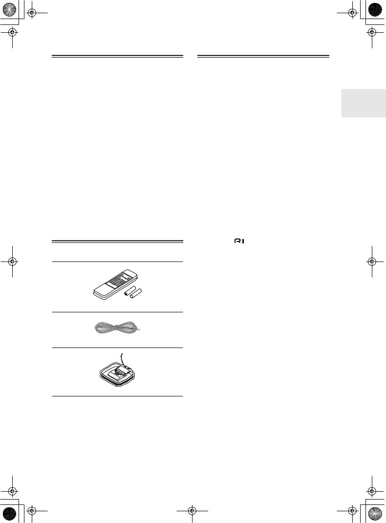
Supplied Accessories
Make sure you have the following accessories:
Remote controller (RC-330S) & two batteries (AA/R6)
Indoor FM antenna
AM loop antenna
*In catalogs and on packaging, the letter added to the end of the product name indicates the color of the TX-8011. Specifications and operation are the same regardless of color.
Contents |
|
|
Important Safeguards........................................ |
2 |
|
Precautions ........................................................ |
|
4 |
Features.............................................................. |
|
5 |
Supplied Accessories ....................................... |
5 |
|
Contents ............................................................. |
|
5 |
Front & Rear Panels .......................................... |
6 |
|
Front Panel........................................................ |
|
6 |
Display............................................................... |
|
7 |
Rear Panel ........................................................ |
|
8 |
Remote Controller ............................................. |
9 |
|
Installing the Batteries ..................................... |
10 |
|
Using the Remote Controller ........................... |
10 |
|
Connections ..................................................... |
|
11 |
Connecting Speakers ...................................... |
11 |
|
Connecting the Supplied FM & AM Indoor |
|
|
Antennas ......................................................... |
|
12 |
Connecting an Outdoor FM Antenna............... |
13 |
|
Connecting an Outdoor AM Antenna .............. |
13 |
|
Connecting a CD Player.................................. |
14 |
|
Connecting a Cassette Recorder .................... |
14 |
|
Connecting a Turntable ................................... |
14 |
|
Connecting |
Components ......................... |
15 |
Connecting the Power Cord of Another |
|
|
Component...................................................... |
|
15 |
Connecting the Power Cord ............................ |
16 |
|
Turning On the TX-8011.................................. |
16 |
|
Playing Your Components.............................. |
17 |
|
Selecting the Source Component.................... |
17 |
|
Using a Graphic Equalizer............................... |
17 |
|
Adjusting the Bass, Treble & Balance ............. |
17 |
|
Muting the TX-8011......................................... |
17 |
|
Using the Sleep Timer..................................... |
18 |
|
Using Headphones.......................................... |
18 |
|
Using the Tuner ............................................... |
|
19 |
Listening to the Radio...................................... |
19 |
|
Tuning into Radio Stations .............................. |
19 |
|
Presetting Radio Stations................................ |
20 |
|
Selecting Presets ............................................ |
20 |
|
Deleting Presets |
.............................................. |
20 |
Recording ......................................................... |
|
21 |
Recording the Input Source............................. |
21 |
|
Tape-to-tape Dubbing ..................................... |
21 |
|
Monitoring While Recording ............................ |
21 |
|
Troubleshooting .............................................. |
|
22 |
Power .............................................................. |
|
22 |
Audio ............................................................... |
|
22 |
Tuner ............................................................... |
|
22 |
Remote Controller ........................................... |
22 |
|
Specifications .................................................. |
|
23 |
5

 TX-8011_E.book Page 6 Friday, July 30, 2004 10:33 AM
Front & Rear Panels
Front Panel
1 |
|
|
|
234 5 6 789 J K |
L |
||||||||||||||||
|
|
|
|
|
|
|
|
|
|
|
|
|
|
|
|
|
|
|
|
|
|
|
|
|
|
|
|
|
|
|
|
|
|
|
|
|
|
|
|
|
|
|
|
|
|
|
|
|
|
|
|
|
|
|
|
|
|
|
|
|
|
|
|
|
|
|
|
|
|
|
|
|
|
|
|
|
|
|
|
|
|
|
|
|
|
|
|
|
|
|
|
|
|
|
|
|
|
|
|
|
|
|
|
|
|
|
|
|
|
|
|
|
|
|
|
|
|
|
|
|
|
|
|
|
|
|
|
|
|
|
|
|
|
|
|
|
|
|
|
|
|
|
|
|
|
|
|
|
|
|
|
|
|
|
|
|
|
|
|
|
|
|
|
|
|
|
|
|
|
|
|
|
|
|
|
|
|
|
|
|
|
|
|
|
|
|
|
|
|
|
|
|
|
|
|
|
|
|
|
|
|
|
|
|
|
|
|
|
|
|
|
|
|
|
|
|
|
|
|
|
|
|
|
|
|
|
|
|
|
|
|
|
|
|
|
|
|
|
|
|
|
|
|
|
|
|
|
|
|
|
|
|
|
|
|
|
|
|
|
|
|
|
|
M N O P Q R S
For detailed information, refer to the pages in parentheses.
ASTANDBY/ON button (16)
This button is used to set the TX-8011 to On or Standby.
BSTANDBY indicator (16)
This indicator lights up when the TX-8011 is in Standby mode, and it flashes while a signal is being received from the remote controller.
CRemote control sensor (10)
This sensor receives control signals from the remote controller.
DTUNING [ ]/[
]/[ ] buttons (19)
These buttons are used to tune into radio stations.
EDIRECT TUNING button (19)
This button is used to select a station by entering the frequency.
FDisplay
See “Display” on page 7 for more information.
GMEMORY button (20)
This button is used to preset radio stations.
HFM MODE button (20)
This button is used to select the FM radio Auto and Mono modes.
IGROUP button (20)
This button is used to select the radio preset groups.
JNumber buttons (20)
These buttons are used to select preset radio stations, and to select stations by frequency.
KSCAN button (20)
This button is used to scan preset radio stations.
LVOLUME control (17)
This control is used to set the volume of the TX-8011.
MPHONES jack (18)
This 1/4-inch phone jack is for connecting a standard pair of stereo headphones.
NSPEAKERS A & B buttons (17)
These buttons are used to turn speaker sets A and B on and off.
OTAPE 2 MONITOR button (17, 21)
This button is used to select the component connected to the TAPE 2 IN jacks, or a graphic equalizer connected to the TAPE 2 IN/OUT jacks. Regardless of which input source is selected, the component connected to the TAPE 2 IN jacks will be heard when TAPE 2 indicator lights up.
PInput selector buttons (17, 21)
These buttons are used to select the input sources.
QBASS control (17)
This control is used to adjust the level of bass sounds.
RTREBLE control (17)
This control is used to adjust the level of treble sounds.
SBALANCE control (17)
This control is used to adjust the left and right balance.
6

 TX-8011_E.book Page 7 Friday, July 30, 2004 10:33 AM
Front & Rear Panels—Continued
Display
1 |
23 |
4 |
5 |
|
6 7 8 |
9J |
||
|
|
SPEAKERS A B |
AUDIO MUTE |
FM MUTE |
TUNED |
MEMORY |
GROUP |
|
|
STEREO |
T-2 MONITOR |
|
ON OFF |
STEREO |
|
A B C |
|
|
MODE |
|
|
|
|
|
|
SLEEP |
|
AUTO |
|
|
|
|
kHz |
|
|
|
MONO |
|
|
|
|
|
CH MIN |
|
|
|
|
|
|
MHz |
|
||
|
|
|
|
|
|
|
||
K
ASTEREO MODE AUTO/FM MUTE ON indicators (19)
These indicators light up when the tuner is tuned to an FM station and Stereo mode is selected.
BSTEREO MODE MONO/FM MUTE OFF indicators (19)
These indicators light up when the tuner is tuned to an FM station and Mono mode is selected.
CT-2 MONITOR indicator (17, 19)
This indicator lights up when TAPE 2 is selected. Regardless of which input source is selected, the component connected to the TAPE 2 IN jacks will be heard when this indicator lights up.
DSPEAKERS A B indicators (17)
These indicators show which speakers are on or off.
EAUDIO MUTE indicator (17)
This indicator flashes when the TX-8011 is muted.
F TUNED
TUNED  indicator (19)
GSTEREO indicator (19)
This indicator lights up when the tuner is tuned to a stereo FM station.
HMEMORY indicator (20)
This indicator lights up when presetting radio stations.
IGROUP A B C indicators
These indicators show which radio preset group is selected.
JSLEEP indicator (18)
This indicator lights up when the Sleep function has been set.
KMessage area
This area of the display shows various information about the currently selected source.
This indicator lights up when the TX-8011 is tuned into a radio station.
7

 TX-8011_E.book Page 8 Friday, July 30, 2004 10:33 AM
Front & Rear Panels—Continued
Rear Panel
1 |
|
2 |
|
3 |
4 |
5 |
|
AM |
|
|
|
|
|
|
|
ANTENNA |
|
|
|
|
GND |
|
|
|
|
|
|
|
FM 75 |
|
|
|
|
SPEAKERS |
|
|
|
|
|
R |
L |
IN |
IN |
OUT |
IN |
OUT |
IN |
A |
|
|
|
|
|
A |
|
L |
|
|
|
|
L |
|
|
|
|
|
|
B |
B |
6
REMOTE
CONTROL
AC OUTLET
AC 120V 60Hz
SWITCHED
120W 1A MAX.
R |
|
R |
PHONO CD |
TAPE 1 |
TAPE 2 |
78 9 J
A Grounding screw (14) |
G PHONO IN (14) |
This screw is for connecting a turntable’s ground wire.
BAM ANTENNA (12, 13)
These push terminals are for connecting an AM antenna.
CFM ANTENNA (12, 13)
This socket is for connecting an FM antenna.
DSPEAKERS A (11)
These lever terminals are for connecting speaker set A.
ESPEAKERS B (11)
These lever terminals are for connecting speaker set B.
F (15)
(15)
These  (Remote Interactive) jacks can be connected to the
  jacks on other Onkyo CD player and cassette recorder. The TX-8011’s remote controller can then be used to control those components.
Note:
To use  , you must make an analog audio connection between the TX-8011 and the other component.
  can only be used with Onkyo components.
These jacks can be used to connect a turntable with a moving-magnet cartridge.
HCD IN (14)
These jacks can be used to connect a CD player with an analog output.
ITAPE 1, 2 IN/OUT (14)
This analog audio input and output can be used to connect a cassette recorder, CD recorder, or other recorder with an analog input and output. Alternatively, they could be used to connect a graphic equalizer.
JAC OUTLET (15)
This switched AC outlet can be used to supply power to another component.
8
 Loading...