


AM/FM Tuner
T-4355
Instruction Manual
Thank you for purchasing an Onkyo AM/FM Tuner. Please read this manual thoroughly before making connections and plugging in the unit.
Following the instructions in this manual will enable you to obtain optimum performance and listening enjoyment from your new Tuner.
Please retain this manual for future reference.
Contents
Introduction .................................... |
2 |
Connections ................................. |
10 |
Enjoying Audio Sources.............. |
14 |
Troubleshooting ........................... |
20 |
Specifications .............................. |
21 |
En
WARNING:
TO REDUCE THE RISK OF FIRE OR ELECTRIC SHOCK, DO NOT EXPOSE THIS APPARATUS TO RAIN OR MOISTURE.
CAUTION:
TO REDUCE THE RISK OF ELECTRIC SHOCK, DO NOT REMOVE COVER (OR BACK). NO USER-SERVICEABLE PARTS INSIDE. REFER SERVICING TO QUALIFIED SERVICE PERSONNEL.
WARNING |
|
AVIS |
RISK OF ELECTRIC SHOCK |
|
RISQUE DE CHOC ELECTRIQUE |
DO NOT OPEN |
|
NE PAS OUVRIR |
|
|
|
The lightning flash with arrowhead symbol, within an equilateral triangle, is intended to alert the user to the presence of uninsulated “dangerous voltage” within the product’s enclosure that may be of sufficient
magnitude to constitute a risk of electric shock to persons.
The exclamation point within an equilateral triangle is intended to alert the user to the presence of important operating and maintenance (servicing) instructions in the literature accompanying the appliance.
Important Safety Instructions
1.Read these instructions.
2.Keep these instructions.
3.Heed all warnings.
4.Follow all instructions.
5.Do not use this apparatus near water.
6.Clean only with dry cloth.
7.Do not block any ventilation openings. Install in accordance with the manufacturer’s instructions.
8.Do not install near any heat sources such as radiators, heat registers, stoves, or other apparatus (including amplifiers) that produce heat.
9.Do not defeat the safety purpose of the polarized or grounding-type plug. A polarized plug has two blades with one wider than the other. A grounding type plug has two blades and a third grounding prong. The wide blade or the third prong are provided for your safety. If the provided plug does not fit into your outlet, consult an electrician for replacement of the obsolete outlet.
10.Protect the power cord from being walked on or pinched particularly at plugs, convenience receptacles, and the point where they exit from the apparatus.
11.Only use attachments/accessories specified by the manufacturer.
12.Use only with the cart, stand, tripod, bracket, or table specified by the manufacturer, or sold with the apparatus. When a cart is used, use cau-
tion when moving the cart/apparatus combination to avoid injury from tip-over.
PORTABLE CART WARNING
S3125A 
13.Unplug this apparatus during lightning storms or when unused for long periods of time.
14.Refer all servicing to qualified service personnel. Servicing is required when the apparatus has been damaged in any way, such as power-supply cord or plug is damaged, liquid has been spilled or objects have fallen into the apparatus, the apparatus has been exposed to rain or moisture, does not operate normally, or has been dropped.
15.Damage Requiring Service
Unplug the apparatus from the wall outlet and refer servicing to qualified service personnel under the following conditions:
A.When the power-supply cord or plug is damaged,
B.If liquid has been spilled, or objects have fallen into the apparatus,
C.If the apparatus has been exposed to rain or water,
D.If the apparatus does not operate normally by following the operating instructions. Adjust only those controls that are covered by the operating instructions as an improper adjustment of other controls may result in damage and will often require extensive work by a qualified technician to restore the apparatus to its normal operation,
E.If the apparatus has been dropped or damaged in any way, and
F.When the apparatus exhibits a distinct change in performance this indicates a need for service.
16.Object and Liquid Entry
Never push objects of any kind into the apparatus through openings as they may touch dangerous voltage points or short-out parts that could result in a fire or electric shock.
The apparatus shall not be exposed to dripping or splashing and no objects filled with liquids, such as vases shall be placed on the apparatus.
Don’t put candles or other burning objects on top of this unit.
17.Batteries
Always consider the environmental issues and follow local regulations when disposing of batteries.
18.If you install the apparatus in a built-in installation, such as a bookcase or rack, ensure that there is adequate ventilation.
Leave 20 cm (8") of free space at the top and sides and 10 cm (4") at the rear. The rear edge of the shelf or board above the apparatus shall be set 10 cm (4") away from the rear panel or wall, creating a fluelike gap for warm air to escape.
2
Precautions
1.Recording Copyright—Unless it’s for personal use only, recording copyrighted material is illegal without the permission of the copyright holder.
2.AC Fuse—The AC fuse inside the unit is not userserviceable. If you cannot turn on the unit, contact your Onkyo dealer.
3.Care—Occasionally you should dust the unit all over with a soft cloth. For stubborn stains, use a soft cloth dampened with a weak solution of mild detergent and water. Dry the unit immediately afterwards with a clean cloth. Don’t use abrasive cloths, thinners, alcohol, or other chemical solvents, because they may damage the finish or remove the panel lettering.
4.Power WARNING
BEFORE PLUGGING IN THE UNIT FOR THE FIRST TIME, READ THE FOLLOWING SECTION CAREFULLY.
AC outlet voltages vary from country to country. Make sure that the voltage in your area meets the voltage requirements printed on the unit’s rear panel (e.g., AC 230 V, 50 Hz or AC 120 V, 60 Hz).
The power cord plug is used to disconnect this unit from the AC power source. Make sure that the plug is readily operable (easily accessible) at all times.
Some models have a voltage selector switch for compatibility with power systems around the world. Before you plug in such a model, make sure that the voltage selector is set to the correct voltage for your area.
5.Never Touch this Unit with Wet Hands—Never handle this unit or its power cord while your hands are wet or damp. If water or any other liquid gets inside this unit, have it checked by your Onkyo dealer.
6.Handling Notes
•If you need to transport this unit, use the original packaging to pack it how it was when you originally bought it.
•Do not leave rubber or plastic items on this unit for a long time, because they may leave marks on the case.
•This unit’s top and rear panels may get warm after prolonged use. This is normal.
•If you do not use this unit for a long time, it may not work properly the next time you turn it on, so be sure to use it occasionally.
For British models
Replacement and mounting of an AC plug on the power supply cord of this unit should be performed only by qualified service personnel.
IMPORTANT
The wires in the mains lead are coloured in accordance with the following code:
Blue: Neutral Brown: Live
As the colours of the wires in the mains lead of this apparatus may not correspond with the coloured markings identifying the terminals in your plug, proceed as follows:
The wire which is coloured blue must be connected to the terminal which is marked with the letter N or coloured black.
The wire which is coloured brown must be connected to the terminal which is marked with the letter L or coloured red.
IMPORTANT
The plug is fitted with an appropriate fuse. If the fuse needs to be replaced, the replacement fuse must approved by ASTA or BSI to BS1362 and have the same ampere rating as that indicated on the plug. Check for the ASTA mark or the BSI mark on the body of the fuse.
If the power cord’s plug is not suitable for your socket outlets, cut it off and fit a suitable plug. Fit a suitable fuse in the plug.
For European Models
Declaration of Conformity
We, ONKYO EUROPE ELECTRONICS GmbH LIEGNITZERSTRASSE 6, 82194 GROEBENZELL, GERMANY
declare in own responsibility, that the ONKYO product described in this instruction manual is in compliance with the corresponding technical standards such as EN60065, EN55013, EN55020 and EN61000-3-2, -3-3.
GROEBENZELL, GERMANY
K. MIYAGI
ONKYO EUROPE ELECTRONICS GmbH
3
Features
30 AM/FM Presets
Automatic AM/FM Scan Tuning
Selectable Character Display
RDS (PS/RT) (European models only)
Audiophile-Grade Capacitor
Hi-Rigidity, Anti-Resonant Chassis
Aluminium Front Panel
RI Remote Compatible
Supplied Accessories
Make sure you have the following accessories:
Audio cable (80 cm)
Before Using this Unit
•Turn off the power before changing the switch settings.
•On changing the switch settings, T-4355 is initialized to its factory defaults. Radio presets and other settings are deleted.

 cable (80 cm)
To use 
 , the T-4355 must be connected with an
 cable and an audio cable.
Indoor FM antenna
AM loop antenna
In catalogs and on packaging, the letter added to the end of the product name indicates the color of the T-4355. Specifications and operation are the same regardless of color.
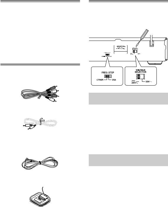
Setting the AM Tuning Step Frequency (Worldwide models only)
Worldwide models are equipped with a switch that controls the AM band tuning steps. Please set this switch to match the AM band tuning step frequency in your area.
USA: |
Set this switch to USA when T-4355 is used |
|
in the 10 kHz tuning step area. North Amer- |
|
ica is the major area using the 10 kHz step |
|
frequency. |
OTHER: Set this switch to OTHER when T-4355 is used in the 9 kHz tuning step area.
Setting the Voltage Selector (Worldwide models only)
Worldwide models are equipped with a voltage selector to conform with local power supplies.Be sure to set this switch to match the voltage of the power supply in your area before plugging in the unit.
Determine the proper voltage for your area: 220-240 V or 120 V.
If the preset voltage is not correct for your area, insert a screwdriver into the groove in the switch. Slide the switch all the way to the right (120 V) or to the left (220-240 V), whichever is appropriate.
4

Table of Contents |
|
Introduction |
|
Important Safety Instructions..................................................................................... |
2 |
Precautions.................................................................................................................. |
3 |
Features ....................................................................................................................... |
4 |
Supplied Accessories ................................................................................................. |
4 |
Before Using this Unit................................................................................................. |
4 |
Setting the AM Tuning Step Frequency (Worldwide models only) ........................ |
4 |
Setting the Voltage Selector (Worldwide models only).......................................... |
4 |
Table of Contents ........................................................................................................ |
5 |
Front & Rear Panels .................................................................................................... |
6 |
Front Panel ............................................................................................................ |
6 |
Display................................................................................................................... |
7 |
Rear Panel............................................................................................................. |
7 |
Remote Controller ....................................................................................................... |
8 |
RC-627S Remote Controller (supplied with the A-9355/A-9155 Integrated |
|
Amplifier) ............................................................................................................ |
8 |
Using the Remote Controller ................................................................................. |
9 |
Connections |
|
Connecting the T-4355 .............................................................................................. |
10 |
Connecting an amplifier....................................................................................... |
10 |
About the System Functions................................................................................ |
11 |
Connecting Antennas ............................................................................................... |
12 |
Connecting the Indoor FM Antenna..................................................................... |
12 |
Connecting the AM Loop Antenna....................................................................... |
12 |
Connecting an Outdoor FM Antenna................................................................... |
13 |
Connecting an Outdoor AM Antenna................................................................... |
13 |
Enjoying Audio Sources |
|
Turning On the T-4355 .............................................................................................. |
14 |
Listening to the Radio............................................................................................... |
14 |
Tuning into Radio Stations Manually ................................................................... |
14 |
Presetting All Stations Automatically (Auto Preset)............................................. |
15 |
Presetting Stations Manually ............................................................................... |
15 |
Selecting Preset Stations .................................................................................... |
16 |
Naming Presets ................................................................................................... |
17 |
Deleting Presets .................................................................................................. |
18 |
Displaying Information ......................................................................................... |
18 |
FM Mode ............................................................................................................. |
18 |
Tuner Operation with the RC-627S Remote Controller (supplied with the |
|
A-9355/A-9155)................................................................................................ |
18 |
Using RDS (European models only).................................................................... |
19 |
Others |
|
Troubleshooting ........................................................................................................ |
20 |
Specifications ............................................................................................................ |
21 |
5
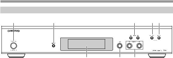
Front & Rear Panels
Front Panel
|
|
|
|
|
|
|
|
|
|
|
|
For detailed information, refer to the pages in parentheses.
POWER switch (14)
This switch is used to turn on/off the T-4355.
DISPLAY button (18)
This button is used to view various information on the display.
TUNING [ ]/[
]/[ ] buttons (14)
These buttons are used to tune into radio stations. They’re also used when setting the naming presets.
MEMORY button (14)
This button is used to store and delete presets.
FM MODE button (18)
This button is used to set the FM mode to stereo or mono.
Display
See next page.
BAND button (14)
This button is used to select the FM or AM band.
PRESET [ ]/[
]/[ ] buttons (14)
These buttons are used to select presets. They’re also used when setting the naming presets.
6

Front & Rear Panels—Continued
Display
MEM (Memory) indicator
This indicator lights up when storing radio presets.
AUTO indicator
This indicator lights up when the FM mode is Auto Stereo.

 /FM ST indicators
These indicators show the status of the radio reception.
RDS indicator (European models only)
This indicator lights up when tuned to an FM station that supports RDS.
Message area
Various information is displayed here, including preset number, tuning frequency, preset name, and so on.
Rear Panel
|
|
|
|||||||||||||
|
|
|
|
|
|
|
|
|
|
|
|
|
|
|
|
|
|
|
|
|
|
|
|
|
|
|
|
|
|
|
|
|
|
|
|
|
|
|
|
|
|
|
|
|
|
|
|
|
|
|
|
|
|
|
|
|
|
|
|
|
|
|
|
|
|
|
|
|
|
|
|
|
|
|
|
|
|
|
|
|
|
|
|
|
|
|
|
|
|
|
|
|
|
|
|
|
|
|
|
|
|
|
|
|
|
|
|
|
|
|
|
|
|
|
|
|
|
|
|
|
|
|
|
|
|
|
|
For detailed information, refer to the pages in parentheses.
ANALOG AUDIO OUTPUT (10)
These output jacks should be connected to an analog audio input on the amplifier by using the supplied audio cable.

 REMOTE CONTROL (11)
These two identical 
 (Remote Interactive) jacks can be connected to the
 jacks on your other Onkyo components for interactive control. To use

 , the T-4355 must be connected with an
 cable and an audio cable.
AM ANTENNA (12)
These push terminals are for connecting the supplied AM loop antenna or an outdoor AM antenna.
FM ANTENNA (75:) (12)
This jack is for connecting the supplied indoor FM antenna or an outdoor FM antenna.
FREQ. STEP switch (4)
For Worldwide models only.
VOLTAGE SELECTOR switch (4)
For Worldwide models only.
Power cord (14)
The power cord should be connected to a suitable power source.
See pages 10–13 for connection information.
7
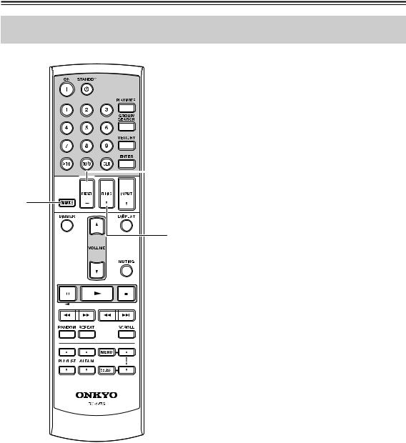
Remote Controller
RC-627S Remote Controller (supplied with the A-9355/A-9155 Integrated Amplifier)
BAND button (14)


This button can be used to select the FM or AM band.
If the T-4355 and A-9355/A-9155 are connected with an 
 cable, pressing this button while the entire system is on Standby will turn on only the T-4355 and A-9355/A-9155. All other components will remain on Standby.
FM MODE button (18)
This button can be used to set the FM mode to stereo or mono.
PRESET [+]/[–] buttons (18)
When the input source on the A-9355/A-9155 is set to TUNER, these buttons can be used to select presets.
TUNING [ ]/[
]/[ ] buttons (18)
When the input source on the A-9355/A-9155 is set to TUNER, these buttons can be used to tune into stations.
* Any remote controller for Onkyo amplifier is available to control T-4355 in a condition of the 
 connection. (On some remote controllers, some buttons shown in the figure are missing. The corresponding functions cannot be controlled by the remote controller.)
8
 Loading...