


250 EXC RACING
OWNERS’S MANUAL
MANUALE D’USO
MANUEL D’UTILISATION
MANUAL DE INSTRUCCIONES
2003
BEDIENUNGSANLEITUNG
Art.Nr. 3.210.50 04/2002
250 EXC RACING, 450/525 SX, EXC, MXC RACING
ENGLISH
1
IMPORTANT
WE STRONGLY SUGGEST THAT YOU READ THIS MANUAL
CAREFULLY AND COMPLETELY BEFORE GOING ON YOUR FIRST
RIDE. IT CONTAINS A GREAT DEAL OF INFORMATION AND
ADVICE WHICH WILL HELP YOU USE AND HANDLE YOUR BIKE
PROPERLY. IN YOUR OWN INTEREST, PLEASE PAY PARTICULAR
ATTENTION TO NOTICES THAT ARE MARKED AS FOLLOWS:
WARNING
IGNORING THESE INSTRUCTIONS, CAN ENDANGER YOUR
BODY AND YOUR LIFE.
!
CAUTION
!
IGNORING THESE INSTRUCTIONS COULD CAUSE DAMAGE TO
PARTS OF YOUR MOTORCYCLE OR THAT THE MOTOR-CYCLE
IS NOT ROAD-SAFE ANYMORE.
Please insert the serial numbers of your motorcycle in the boxes below
Frame number
Engine number
Key number
Stamp of dealer
Tampering with noise control system prohibited
Owners are warned that the law may prohibit:
(a) The removal or rendering inoperative by any person other than for purposes of mainten-
ance, repair or replacement, of any device or element of design incorporated into any new
vehicle for the purpose of noise control prior to its sale or delivery to the ultimate purchaser
or while it is in use; and
(b) the use of the vehicle after such device or element of design has been removed or rendered
inoperative by any person.
COMSUMER INFORMATION FOR AUSTRALIA ONLY
KTM S
PORTMOTORCYCLE
AG
RESERVES THE RIGHT TO MODIFY ANY EQUIPMENT
,
TECHNICAL SPECIFICATIONS
,
COLORS
,
MATERIALS
,
SERVICES OFFERED AND RENDERED
,
AND THE LIKE SO AS TO ADAPT THEM TO LOCAL CONDITIONS WITHOUT
PREVIOUS ANNOUNCEMENT AND WITHOUT GIVING REASONS
,
OR TO CANCEL ANY OF THE ABOVE ITEMS WITHOUT SUBSTI
-
TUTING THEM WITH OTHERS
. I
TSHALL BE ACCEPTABLE TO STOP MANUFACTURING A CERTAIN MODEL WITHOUT PREVIOUS
ANNOUNCEMENT
. I
N THE EVENT OF SUCH MODIFICATIONS
,
PLEASE ASK YOUR LOCAL
KTM
DEALER FOR INFORMATION
.

ENGLISH
2
Introduction
We would like to congratulate you on your purchase of a KTM motorcycle.
You are now the owner of a state-of-the-art sport motorcycle that guarantees to bring
you lots of fun and enjoyment, provided that you clean and maintain it appropriately.
Before you go for your first ride, be sure to read this manual carefully and thoroughly in
order to familiarize yourself with how to operate your new motorcycle and with its
characteristics, even if this means that you will have to dedicate some of your valuable
time to this task. Only by doing so will you learn how to tune your motorcycle to your
specific needs and how to protect yourself against injury. Besides, this manual contains
important information on motorcycle maintenance. At the time this manual was typeset,
it was up-to-date with the latest state of this production series. It cannot be completely
ruled out, however, that minor discrepancies may exist resulting from further design
upgrades of these motorcycles.This manual is an important part of your motorcycle and
should be passed on to any subsequent owner in case you decide to sell it.
We expressly point out that work marked with an asterisk in the chapter "Maintenance
work on the chassis and engine" must be performed. If maintenance work should
become necessary during a competition it should be performed by a trained mechanic.
KTM strongly recommends that all service work to your KTM should be performed by a
qualified KTM dealer.
For your own safety, use KTM-approved parts and accessories only. KTM is not liable
for damage that arises in connection with the use of other products.
Take special care to follow the recommended run in, inspection, and maintenance
intervals. Heeding these guidelines will significantly increase the life of your motorcycle.
To ensure that all work to your KTM is performed properly and to avoid warranty
conflicts, KTM recommends that you always have your KTM serviced by a recognized
and qualified KTM dealer.
Off-road motorcycle driving is a wonderful sport and we hope that you will be able to
enjoy it to the full. It may, however, involve potential problems for the environment or
lead to conflicts with others. These problems or conflicts can be avoided if the motorcycle
is used responsibly. To safeguard the future of motorcycle sports, make sure that you use
the motorcycle in accordance with the law, show that you are environmentally conscious
and respect the rights of others.
We wish you a lot of fun when driving !
KTM SPORTMOTORCYCLE AG
5230 MATTIGHOFEN, AUSTRIA
Attachments: Spare parts manual chassis & engine
ALL RIGHTS RESERVED TO MAKE ALTERATIONS TO DESIGN AND MODEL.
©
by KTM SPORTMOTORCYCLE AG, AUSTRIA All rights reserved

ENGLISH
3
IMPORTANT LIMITED WARRANTY AND
LIMITED GUARANTEE INFORMATION
KTM sports motorcycles are designed and constructed to resist the usual
wear and tear of normal use in competitions.
The motorcycles comply with the regulations and categories currently in
effect with the leading international motorcycle associations.
Observance of the service, maintenance and tuning instructions for the
engine and chassis specified in the Owner's Manual is a prerequisite for
faultless operation and the avoidance of premature wear. An improperly
tuned chassis can lead to damage and breakage of the chassis components
(see chapter on checking the basic chassis setting).
The service work specified in the "Lubrication and Maintenance Schedule"
must be performed and service records must be kept for warranty
documentation. Lack of proper service and maintenance records or
documentation could void warranty.
The fuels and lubricants specified in the Owner's Manual or fluids with
equivalent specifications must be used in accordance with the maintenance
schedule.
No claims can be filed under the warranty for damage or consequential
damage caused by manipulations or conversions to the motorcycle.
The use of the motorcycle under extreme conditions, e.g. on extremely
muddy and wet terrain, can lead to higher than average wear on
components such as the drive train or the brakes. In this case it may become
necessary to service or replace wear parts before the service limit specified in
the maintenance schedule has been reached.
THE SX/SXS, MXC AND OTHER “COMPETITION ONLY“ LABELED
MODELS ARE PROHIBITED ON PUBLIC ROADS.
“On the road“ approved models are only allowed on public roads in the
original homologated (throttled) version. Without this performance
restriction (i.e. de-throttled), these models are only allowed to be driven
off-road and not on public roads.
The EXC models are designed for off-road sports endurance
competitions(enduro) and not
suitable for predominant motocross use.
Note: The above is a general statement. Specific limited warranty and limited
guarantee information may vary depending upon distribution. Please check
with your local KTM dealer for limited warranty and limited guarantee
information specific to your KTM model and region.
In accordance with the international quality management
ISO 9001 standard, KTM uses quality assurance processes
that lead to the highest possible product quality.

ENGLISH
4
Page
SERIAL NUMBER LOCATIONS . . . . . . . . . . . . . . . . . . . . . .5
Chassis number . . . . . . . . . . . . . . . . . . . . . . . . . . . . . . . .5
Engine number, engine type . . . . . . . . . . . . . . . . . . . . . .5
OPERATION INSTRUMENTS . . . . . . . . . . . . . . . . . . . . . . .5
Clutch lever . . . . . . . . . . . . . . . . . . . . . . . . . . . . . . . . . .5
Hand decompression lever . . . . . . . . . . . . . . . . . . . . . . .5
Hand brake lever . . . . . . . . . . . . . . . . . . . . . . . . . . . . . . .5
Digital speedometer, indicator lamps . . . . . . . . . . . . . . . .6
Electronic speedometer . . . . . . . . . . . . . . . . . . . . . . . . . .6
Tripmaster switch . . . . . . . . . . . . . . . . . . . . . . . . . . . . . .7
Short circuit button (SX/MXC) . . . . . . . . . . . . . . . . . . .11
Combination switch (EXC) . . . . . . . . . . . . . . . . . . . . . . .11
Headlamp switch (EXC USA) . . . . . . . . . . . . . . . . . . . . .11
Flasher switch . . . . . . . . . . . . . . . . . . . . . . . . . . . . . . . .11
Emergency OFF button (EXC) . . . . . . . . . . . . . . . . . . . .11
Emergency OFF switch (EXC Australia) . . . . . . . . . . . . .12
Filler cap . . . . . . . . . . . . . . . . . . . . . . . . . . . . . . . . . . . .12
Fuel tap . . . . . . . . . . . . . . . . . . . . . . . . . . . . . . . . . . . . .12
Choke . . . . . . . . . . . . . . . . . . . . . . . . . . . . . . . . . . . . . .12
Hot start device . . . . . . . . . . . . . . . . . . . . . . . . . . . . . . .13
Shift lever . . . . . . . . . . . . . . . . . . . . . . . . . . . . . . . . . . .13
Kickstarter . . . . . . . . . . . . . . . . . . . . . . . . . . . . . . . . . . .13
Foot brake pedal . . . . . . . . . . . . . . . . . . . . . . . . . . . . . .13
Side stand . . . . . . . . . . . . . . . . . . . . . . . . . . . . . . . . . . .13
Compression damping of fork . . . . . . . . . . . . . . . . . . . .14
Rebound damping of fork . . . . . . . . . . . . . . . . . . . . . . .14
Damping action during compression of shock absorber (SX)
. .14
Compression damping of shock absorber (MXC, EXC)
. .15
Rebound damping of shock absorber (SX, MXC, EXC)
. .15
Steering lock . . . . . . . . . . . . . . . . . . . . . . . . . . . . . . . . .15
GENERAL TIPS AND WARNINGS FOR STARTING THE
MOTORCYCLE . . . . . . . . . . . . . . . . . . . . . . . . . . . . . . . . .16
DRIVING INSTRUCTIONS . . . . . . . . . . . . . . . . . . . . . . . . .17
PERIODIC LUBRICATION AND MAINTENANCE-SCHEDULE
. . .20
MAINTENANCE WORK ON CHASSIS AND ENGINE . . . . .24
Checking and adjusting the steering head bearing . . . . .24
Breather plug front fork . . . . . . . . . . . . . . . . . . . . . . . . .25
Cleaning the dust sleeves of the telescopic fork . . . . . . .25
Adjusting the spring preload on the fork (SX) . . . . . . . .25
Basic suspension setup for the weight of the driver . . . .26
How to change the handlebar position . . . . . . . . . . . . .28
Changing the spring preload of the shock absorber . . . .28
Pivot bearing . . . . . . . . . . . . . . . . . . . . . . . . . . . . . . . . .28
Check chain tension . . . . . . . . . . . . . . . . . . . . . . . . . . .29
Correct chain tension . . . . . . . . . . . . . . . . . . . . . . . . . .29
Chain maintenance . . . . . . . . . . . . . . . . . . . . . . . . . . . .30
Chain wear . . . . . . . . . . . . . . . . . . . . . . . . . . . . . . . . . .30
General information about KTM disc brakes . . . . . . . . .31
Adjusting the free travel at the hand brake lever . . . . . .32
Page
Checking the brake fluid level - front brake . . . . . . . . . .32
Refilling the front brake fluid reservoir . . . . . . . . . . . . . .32
Checking the front brake pads . . . . . . . . . . . . . . . . . . .32
Replacing the front brake pads . . . . . . . . . . . . . . . . . . .33
Changing the basic position of the brake pedal . . . . . .33
Checking the rear brake fluid level . . . . . . . . . . . . . . . .33
Refilling the rear brake fluid reservoir . . . . . . . . . . . . . .33
Checking the rear brake pads . . . . . . . . . . . . . . . . . . . .34
Replacing the rear brake pads . . . . . . . . . . . . . . . . . . .34
Dismounting and mounting the front wheel . . . . . . . . .34
Dismounting and mounting the rear wheel . . . . . . . . .35
Tires, air pressure . . . . . . . . . . . . . . . . . . . . . . . . . . . . .36
Checking the spoke tension . . . . . . . . . . . . . . . . . . . . .36
Replacing the battery of the digital speedometer . . . . .36
Setting the clock . . . . . . . . . . . . . . . . . . . . . . . . . . . . .37
Kilometers or miles . . . . . . . . . . . . . . . . . . . . . . . . . . . .37
Checking/setting distance of the magnetic sensor . . . .38
Battery (MXC/EXC) . . . . . . . . . . . . . . . . . . . . . . . . . . .39
Charging the battery . . . . . . . . . . . . . . . . . . . . . . . . . .39
Fuse (MXC/EXC) . . . . . . . . . . . . . . . . . . . . . . . . . . . . .40
Replacing the headlight/parking light lamp . . . . . . . . .40
Cooling system . . . . . . . . . . . . . . . . . . . . . . . . . . . . . .41
Checking the coolant level . . . . . . . . . . . . . . . . . . . . . .41
Bleeding the cooling system . . . . . . . . . . . . . . . . . . . . .41
Replacing the glassfiber yarn packing of the silencer
. .42
Cleaning the spark arrestor (MXC/EXC USA) . . . . . . . .42
Cleaning the air filter . . . . . . . . . . . . . . . . . . . . . . . . . .43
Checking adjustment of the hand decompression release cable
. .43
Adjusting the throttle cables . . . . . . . . . . . . . . . . . . . . .43
Changing the original position of the clutch lever . . . .44
Checking the oil level of the hydraulic clutch . . . . . . . .44
Bleeding of the hydraulic clutch . . . . . . . . . . . . . . . . . .44
Carburetor adjustment . . . . . . . . . . . . . . . . . . . . . . . . .45
Adjusting the mixture control screw . . . . . . . . . . . . . . .45
Checking the float level . . . . . . . . . . . . . . . . . . . . . . . .45
Draining the float chamber of the carburetor . . . . . . . .46
Oil circuit . . . . . . . . . . . . . . . . . . . . . . . . . . . . . . . . . . .46
Checking the engine oil level . . . . . . . . . . . . . . . . . . . .46
Engine oil . . . . . . . . . . . . . . . . . . . . . . . . . . . . . . . . . . .47
Changing the engine oil . . . . . . . . . . . . . . . . . . . . . . . .47
TROUBLESHOOTING . . . . . . . . . . . . . . . . . . . . . . . . . . . .49
CLEANING . . . . . . . . . . . . . . . . . . . . . . . . . . . . . . . . . . . .51
CONSERVATION FOR WINTER OPERATION . . . . . . . . .51
STORAGE . . . . . . . . . . . . . . . . . . . . . . . . . . . . . . . . . . . . .51
Using after storage . . . . . . . . . . . . . . . . . . . . . . . . . . . .51
TECHNICAL SPECIFICATIONS - ENGINE . . . . . . . . . . . . .52
TECHNICAL SPECIFICATIONS - CHASSIS . . . . . . . . . . . . .55
INDEX . . . . . . . . . . . . . . . . . . . . . . . . . . . . . . . . . . . . . . . .56
WIRING DIAGRAM . . . . . . . . . . . . . . . . . . . . . . . .Appendix
TABLE OF CONTENTS
ENGLISH
5
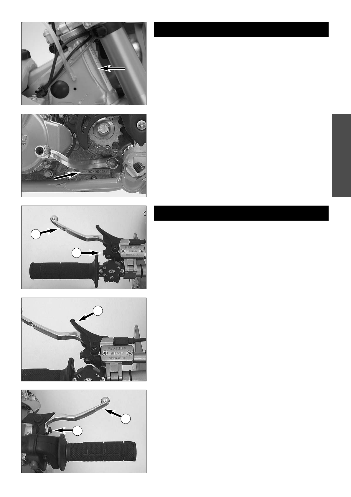
Chassis number
The chassis number is stamped on the right side of the steering head tube.
Enter this number in the field on page no 1.
Engine number, engine type
The engine number and the engine type are stamped into the left side of
the engine below the engine sprocket. Enter this number on page 1.
SERIAL NUMBER LOCATIONS
OPERATION INSTRUMENTS
Clutch lever
The clutch lever 1 is located on the left side of the handlebar. The adjust-
ing screw
A is used to change the original position of the clutch lever (see
maintenance work on chassis and engine).
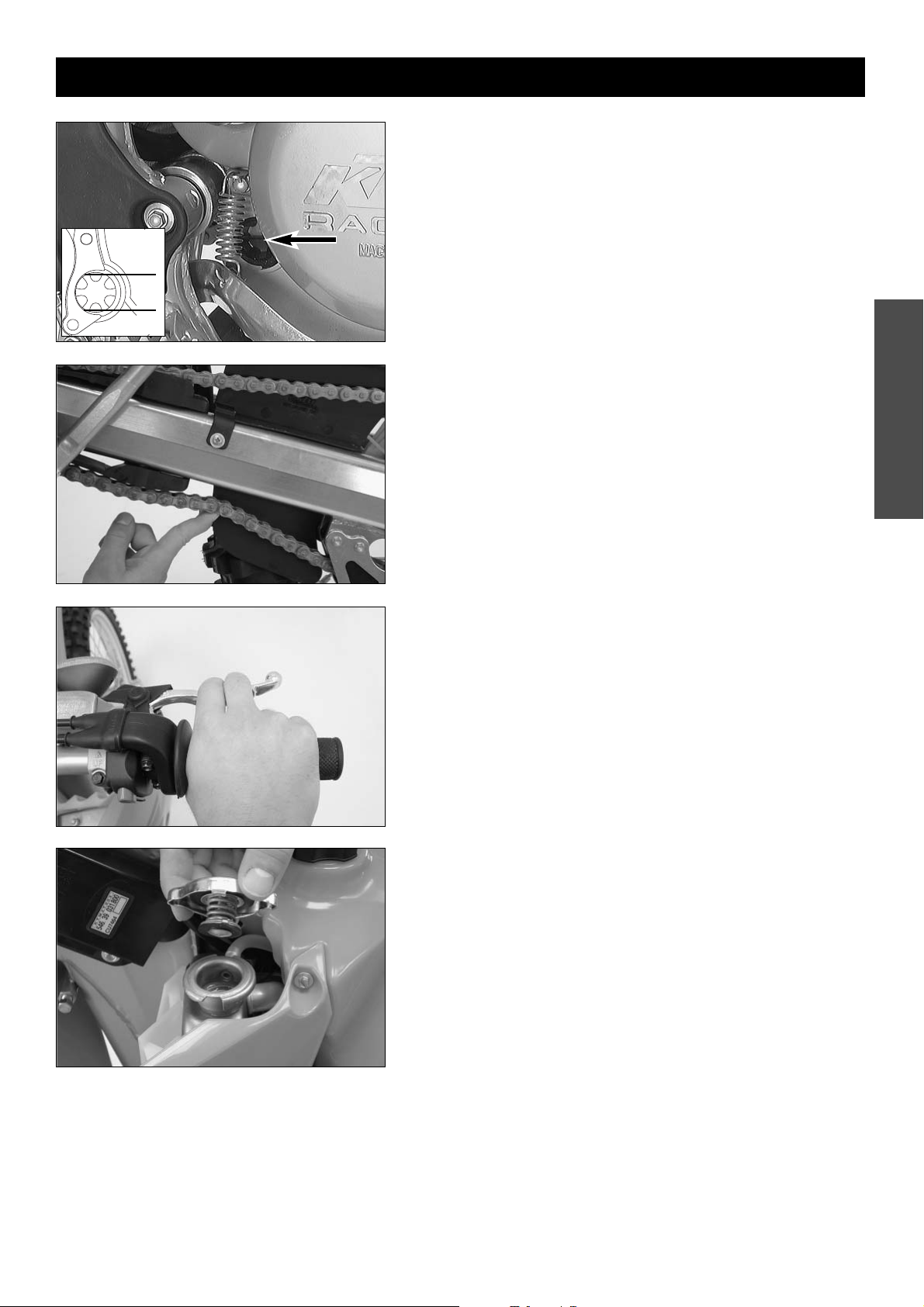
Hand decompression lever
The hand decompression lever 2 is needed only if the carburetor overflows
after a fall. To "pump the engine free", pull the hand decompression lever
during the starting procedure.
The outer end of the lever must provide for a backlash of approx. 10mm
(0.4 in) at all times. Only thereafter may it cause valve motion (to be
recognized by the stronger resistance which the hand decompression lever
encounters).
Hand brake lever
The hand brake lever 3 is mounted on the handlebars on the right and
actuates the front wheel brake. The adjusting screw
B can be used to
change the basic position of the hand brake lever (see "Maintenance").
1
A
2
3
B
ENGLISH
6
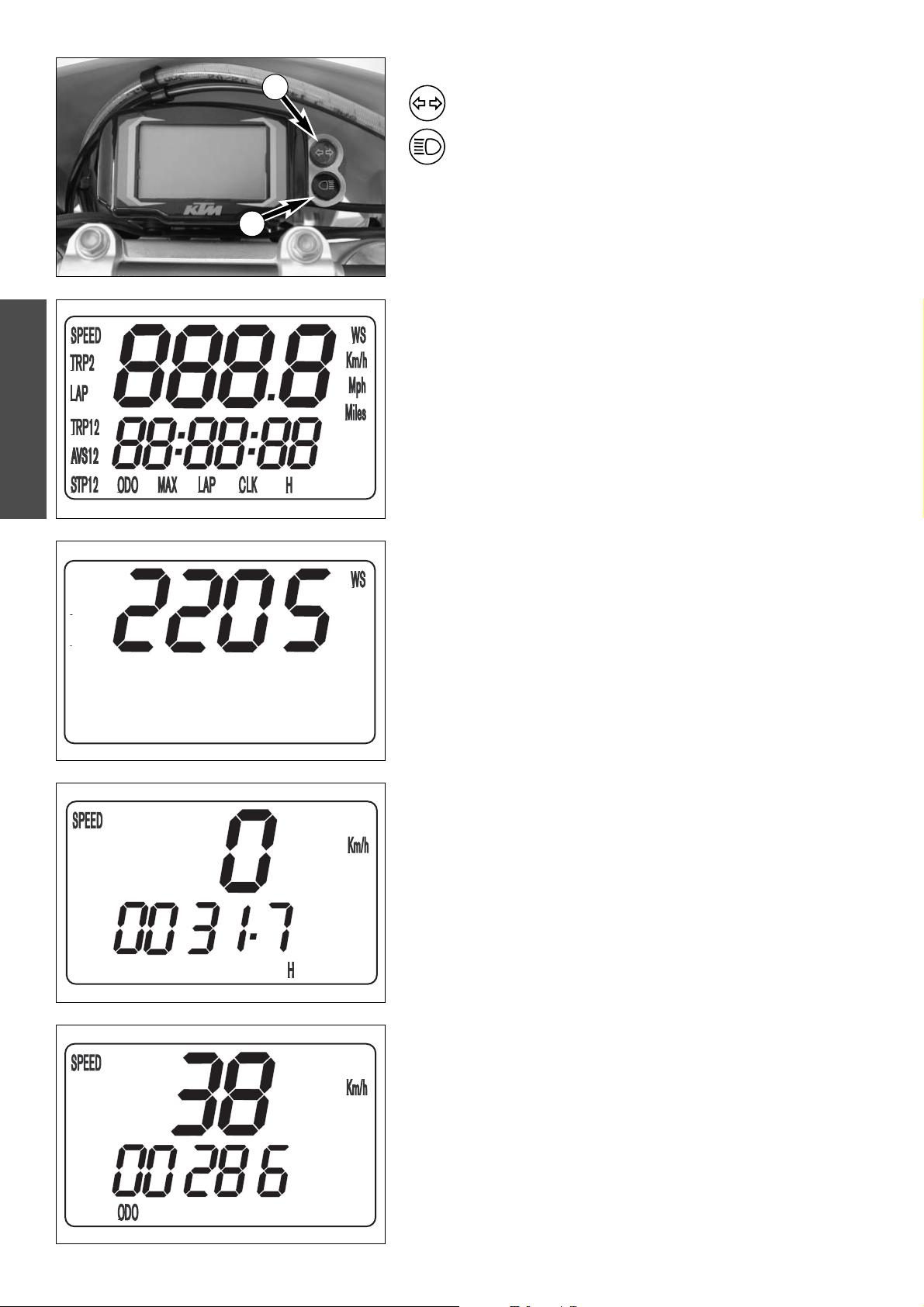
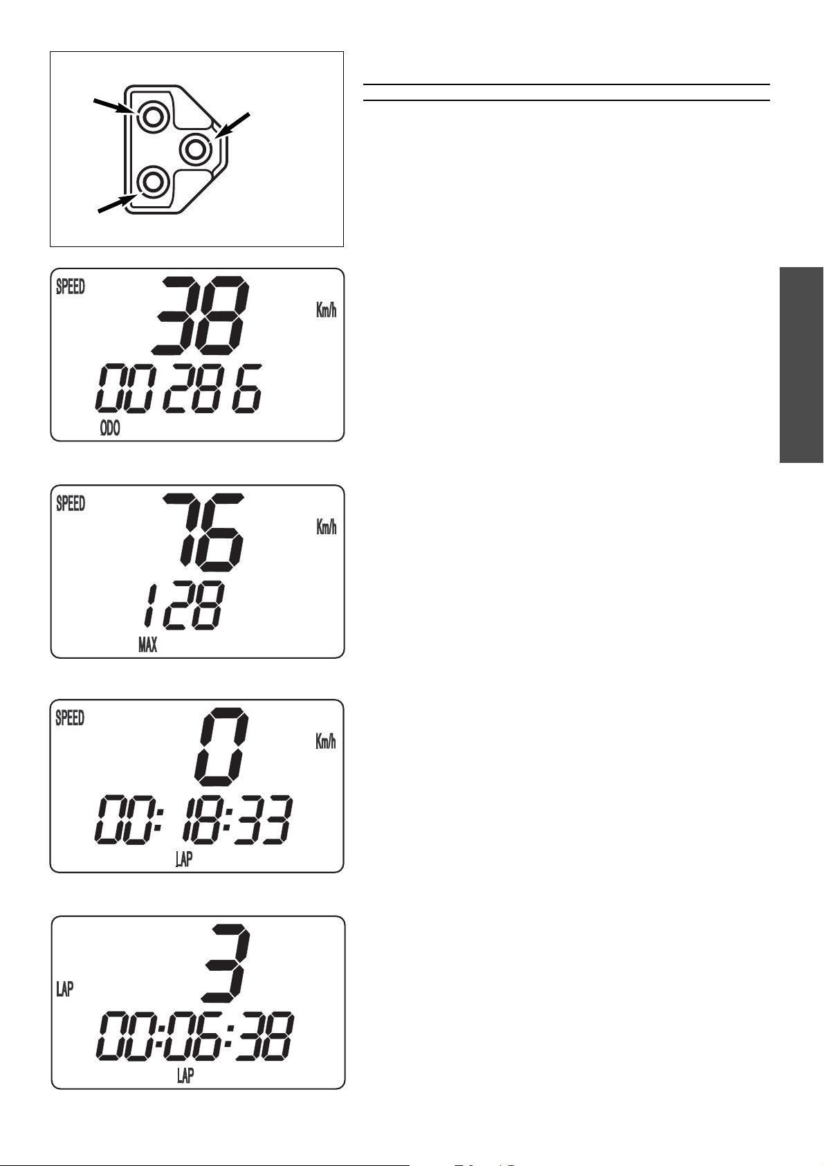
Digital speedometer, indicator lamps
The green control lamp 1 flashes in the same rhythm as the flashing
indicator when the indicator is working.
The blue control lamp
2 lights up when the high beam is on.
Electronic speedometer
The electronic speedometer display is activated as soon as the engine is
switched on and the motorcycle starts to move.
The engine must be started in order for the speedometer to be supplied
with electricity from the generator. An impulse must be received from the
wheel sensor to activate the display; the front wheel must turn at least one
time.
TEST
All of the display elements will light up for 1 second for the function test.
WS (wheel size)
The display will change and briefly show the diameter of the front wheel in
millimeters.
If the front wheel does not turn, the display will automatically change to the
SPEED/H mode.
If the front wheel turns, the display will automatically change to the SPEED
/ODO mode.
SPEED/H (hours) display mode
When you stop driving and no impulses are sent from the wheel sensor, the
display mode will automatically change from SPEED/ODO to SPEED/H. H
shows the operating hours. The operating hour counter starts to count as
soon as you start the engine. The displayed figure cannot be cleared.
Service intervals are indicated in operating hours for some KTM offroad
motorcycles, making the operating hour counter a very practical function.
SPEED/ODO display mode
The SPEED/ODO mode shows the speed and the total kilometers traveled.
When the front wheel stops turning, the display will automatically change
to the SPEED/H mode.
The information will disappear in the display when the front wheel stops
turning for 1 minute.
NOTE:
A Tripmaster switch (part no 583.14.069.244) is available as an accessory
and enhances the electronic speedometer by providing the following
functions:
2x Tripmaster
2x chronometer for the lap time
Average speed
Maximum speed
Clock
Display in miles
1
2
ENGLISH
7
+
–
MODE
Tripmaster switch
The switch has three buttons: MODE, + (plus) and – (minus).
WARNING
DO NOT TRY TO CHANGE THE MODE OR READ THE SETTINGS WHILE DRIVING. YOUR
ATTENTION WILL BE DISTRACTED FROM THE TRAFFIC WHICH CAN EASILY LEAD TO AN
ACCIDENT
.
Electronic speedometer functions provided by the Tripmaster
switch
The display modes on the electronic speedometer will change in the
following order. If not, please read the chapter "ACTIVATING AND
DEACTIVATING THE DISPLAY MODE."
SPEED/ODO display mode
SPEED displays the speed in KPH or MPH. The displayed figure cannot be
cleared.
ODO displays the kilometers or miles traveled. The displayed figure cannot
be cleared.
+
BUTTON no function
–
BUTTON no function
press the MODE
BUTTON to change to the next mode
press and hold the MODE
BUTTON 3 SECONDS to change to the next mode
SPEED/MAX display mode
MAX displays the maximum speed. It is always active.
+
BUTTON no function
–
BUTTON no function
press the MODE
BUTTON to change to the next mode
press and hold the MODE
BUTTON 3 SECONDS to reset the MAX figure to 0
SPEED/LAP display mode
LAP displays the stopped lap time in hours, minutes and seconds.
+
BUTTON Starts and stops the stop watch. The lap time is not reset to 0.
–
BUTTON Stops the running stop watch, stores the lap time and restarts
the stop watch. The time is reset to 0. A total of 10 lap times
can be stored and read in the SPEED/LAP display mode. To
clear all of the stored lap times, hold the MODE button for 3
seconds in the SPEED/LAP mode.
press the MODE
BUTTON to change to the next mode
If no lap time is stored or the motorcycle is driving, the LAP/LAP
mode will be skipped.
press and hold the MODE
BUTTON 3 SECONDS to reset the LAP figure and all
stored lap times to 0
LAP/LAP display mode
The lap number is shown at the top and the lap time in hours, minutes and
seconds at the bottom of the display.
If no lap time is stored or the motorcycle is driving, the LAP/LAP mode will
be skipped.
Hold the MODE button for 3 seconds in the SPEED/LAP mode to clear the
stored lap times.
+
BUTTON changes to the next lap time.
– BUTTON no function
press the MODE
BUTTON to change to the next mode
press and hold the MODE
BUTTON 3 SECONDS to change to the next mode
ENGLISH
8
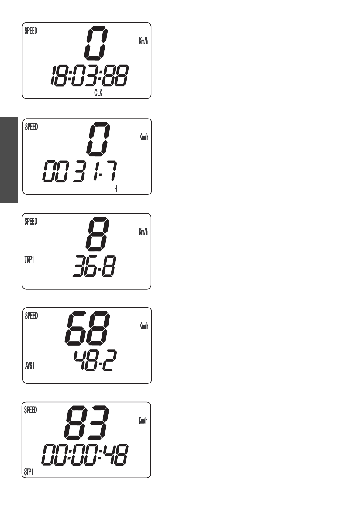
SPEED/CLK (clock) display mode
CLK will display time in hours, minutes and seconds.
+
BUTTON no function
–
BUTTON no function
press the MODE BUTTON to change to the next mode.
press and hold the MODE
BUTTON 3 SECONDS to set the time in the menu
(see SETTING THE CLOCK)
SPEED/H (hours) display mode
When you stop driving and no impulses are sent from the wheel sensor, the
display mode will automatically change from SPEED/ODO to SPEED/H. H
shows the operating hours. The operating hour counter starts to count as
soon as you start the engine. The displayed figure cannot be cleared.
Service intervals are indicated in operating hours for some KTM offroad
motorcycles, making the operating hour counter a very practical function.
+
BUTTON no function
– BUTTON no function
press the MODE
BUTTON to change to the next mode
press and hold the MODE BUTTON 3 SECONDS to change to the SETUP mode
(see REVEALING/CONCEALING functions).
SPEED/TRP1 (trip 1) display mode
The TRP1 trip meter is always active and counts to 999.9. It is used to
measure the length of a trip or the distance between 2 refueling stops.
TRP1 is linked to AVS1 and STP1. The calculation of these figures is
activated by the first impulse received from the wheel sensor (when the
front wheel starts to turn) and stops 3 seconds after the last impulse is
received (when the front wheel has stopped).
The TRP1, AVS1 and STP1 figures are automatically reset to 0 after passing
999.9.
+ BUTTON no function
–
BUTTON no function
press the MODE
BUTTON to change to the next mode.
press and hold the MODE
BUTTON 3 SECONDS to automatically reset the
TRP1, AVS1 and STP1 figures to 0.
SPEED/AVS1 (average speed 1) display mode
AVS1 is always active and shows the average speed based on the TRP1 and
STP1 figures. The calculation of this figure is activated by the first impulse
received from the wheel sensor and stops 3 seconds after the last impulse is
received.
+
BUTTON no function
–
BUTTON no function
press the MODE
BUTTON to change to the next mode
press and hold the MODE BUTTON 3 SECONDS to reset the TRP1, AVS1 and
STP1 figures to 0.
SPEED/STP1 (stop 1) display mode
STP1 shows the traveling time based on TRP1 and continues to count
whenever it receives impulses from the wheel sensor. The calculation of this
figure is activated by the first impulse received from the wheel sensor and
stops 3 seconds after the last impulse is received.
+
BUTTON no function
–
BUTTON no function
press the MODE
BUTTON to change to the next mode
press and hold the MODE
BUTTON 3 SECONDS to reset the TRP1, AVS1 and
STP1 figures to 0.
ENGLISH
9
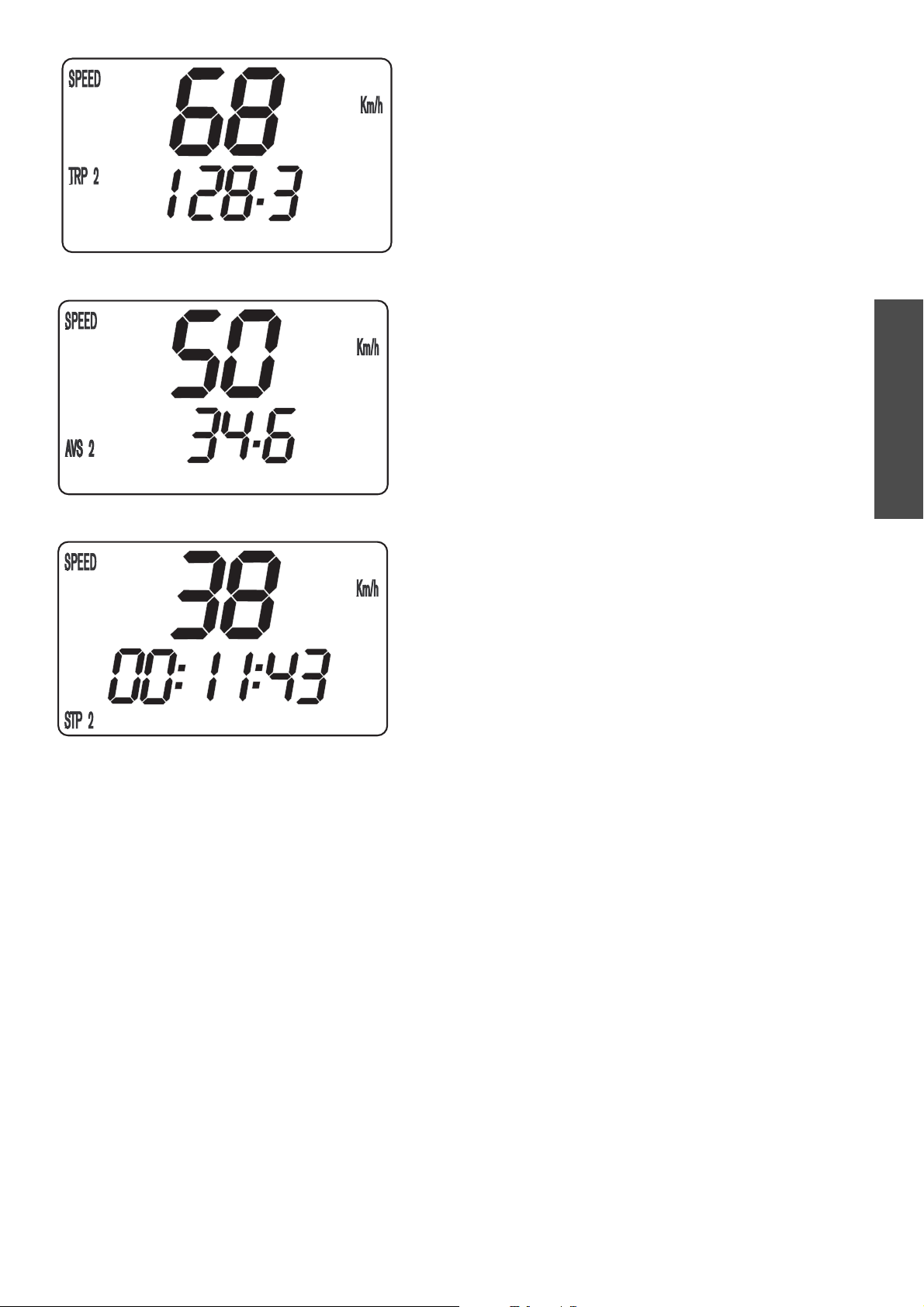
SPEED/TRP2 (trip 2) display mode
The TRP2 trip meter is always active and counts to 999.9. Contrary to
TRP1, the displayed figure can be changed using the + and – buttons. This
is a very useful function for trips taken according to a roadbook.
TRP2 is activated by the first impulse received from the wheel sensor and
stops automatically 3 seconds after the last impulse is received.
+
BUTTON increases the TRP2 figure
–
BUTTON decreases the TRP2 figure
press the MODE
BUTTON to change to the next mode
press and hold the MODE
BUTTON 3 SECONDS to reset TRP2 to 0
SPEED/AVS2 (average speed 2) display mode
AVS2 shows the average speed based on the TRP2 and STP2 figures. The
calculation of this figure is activated by the first impulse received from the
wheel sensor and stops 3 seconds after the last impulse is received.
The displayed figure will deviate from the actual average speed if TRP2 was
changed manually or if STP2 was not stopped after the trip.
+
BUTTON no function
–
BUTTON no function
press the MODE
BUTTON to change to the next mode
press and hold the MODE
BUTTON 3 SECONDS to change to the next mode
SPEED/STP2 (stop 2) display mode
STP2 is a manual stop watch. Start the stop watch by pressing the + but-
ton, press again to hold. Press again to continue timing.
Press the MODE button to change to the next mode. The STP2 display will
blink in the other modes if STP2 continues to run in the background. To
stop STP2, return to the SPEED/STP2 mode and press the + button.
+
BUTTON starts and stops the stop watch
–
BUTTON no function
press the MODE
BUTTON to change to the next mode
press and hold the MODE
BUTTON 3 SECONDS to reset STP2 figures to 0

ENGLISH
10
X
X
X
X
X
X
X
X
X
X
X
X
X
X
X
X
X
X
X
X
X
no function
no function
starts / stops LAP
figure LAP remains
next figure
no function
no function
no function
no function
no function
increases TRP2 figure
no function
starts / stops STP2
Press
+
Display
SPEED / ODO
SPEED / MAX
SPEED / LAP
LAP / LAP
SPEED / CLK
SPEED / H
SPEED / TRP1
SPEED / AVS1
SPEED / STP1
SPEED / TRP2
SPEED / AVS2
SPEED / STP2
OVERVIEW OF TRIPMASTER FUNCTIONS
Standing motorcycle
Driving motorcycle
Press –
Press MODE Hold MODE for 3 sec
no function
no function
stops LAP, stores LAP
figure, resets LAP to 0
no function
no function
no function
no function
no function
no function
decreases TRP2 figure
no function
no function
next display mode
next display mode
next display mode
next display mode
next display mode
next display mode
next display mode
next display mode
next display mode
next display mode
next display mode
next display mode
no function
resets MAX to 0
clears all LAP figures
next display mode
set clock menu
display setup menu
resets TRP1, STP1 and
AVS1 to 0
resets TRP1, STP1 and
AVS1 to 0
resets TRP1, STP1 and
AVS1 to 0
resets TRP2 to 0
next display mode
sets STP2 to 0
ENGLISH
11
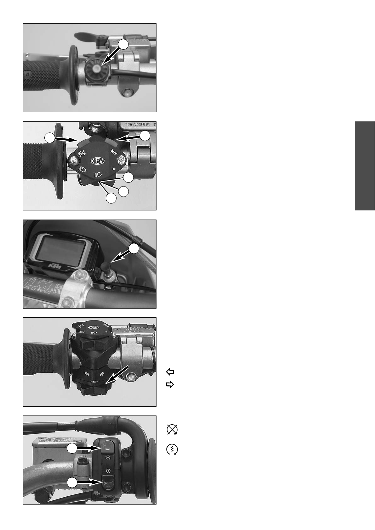
Short circuit button (SX/MXC)
The short circuit button 1 turns off the engine. When pressing this button,
the ignition circuit is short-circuited.
Combination switch (EXC)
The light switch has 2, respectively 3 switch positions.
A = Light off (this function is not available in all models)
B = Low beam on
C = High beam on
You may use button
2 to actuate the horn.
The red short circuit button
3 serves to switch off the engine. Leave the
switch pressed until the engine stops.
Headlamp switch (EXC USA)
In this model the headlamp is switched on with the pull switch 4.
Flasher switch
The flasher switch is a separate unit and is mounted on the left portion of
the handlebar.
The wire harness is designed in a way that whenever you want to use your
bike off-road, you can dismount the entire turn indicator system without
affecting the function of the remaining electrical system.
Flasher left
Flasher right
Emergency OFF button (EXC)
The red emergency-OFF button 5 is arranged adjacent to the
throttle grip. To turn off the engine, push the button until the engine
comes to a standstill.
Pushing the black starter button
6 will actuate the E-starter.
2
A
B
C
3
5
6
4
1
ENGLISH
12
Emergency OFF switch (EXC Australia)
The red emergency-OFF switch 1 is arranged adjacent to the throttle grip.
In this position, the E-starter is operational and the engine can
be started.
In this position, the E-starter and ignition circuits are interrup-
ted. The E-starter cannot be actuated, and the engine will not
start, not even if you attempt to start it with the kickstarter.
Pushing the black starter button
2 will actuate the E-starter.
Filler cap
To open the filler cap: Turn the filler cap counter-clockwise.
To close the filler cap: Put the filler cap on and tighten it by turning it
clockwise.
Install the tank breather hose
3 without kinks.
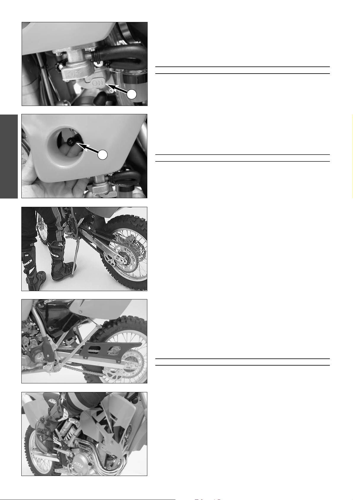
Fuel tap
OFF
In this position the fuel tap is closed. No fuel can flow to the carburetor.
ON During operation the twist grip must be turned to ON. This means
that the fuel can flow to the carburetor. With the twist grip in this
position the tank will be emptied until only the reserve is left.
RES The reserve tank cannot be tapped until the rotating handle is turned
to the RES position. Fill the tank as soon as possible and remember to
turn the rotating handle back to the ON position so that you will have
backup fuel next time, too.
Reserve MXC . . . . . . . . . . . . . 3.0 l (0,8 US gallons)
Reserve EXC . . . . . . . . . . . . . . 1.0 l (0,3 US gallons)
Choke
If you pull the choke button 4 out as far as possible, a bore in the
carburetor will be opened through which the engine may take in additional
fuel. The result is a „fat“ fuel-air mixture of the type needed for cold starts.
To deactivate the choke, push the choke button back into its basic position.
1
2
3
4
ON RESOFF
SX
MXC
EXC
ENGLISH
13
Hot start device (450/525 SX)
If you pull the hot start device 1 out as far as possible, a bore in the
carburetor will be opened through which the engine may take in additional
air. The result is a „lean“ fuel-air mixture of the type needed for hot starts.
To deactivate the hot start device, push the hot start button back into its
basic position.
Shift lever
The shift lever is mounted on the left side of the engine. The position of the
gears is shown in the illustration. Neutral, or the idle speed, is located
between first and second gear.
Kickstarter
The kickstarter is mounted on the right side of the engine. Its upper part
can be swivelled.
Foot brake pedal
The foot brake pedal is located in front of the right footrest. Its basic
position can be adjusted to your seat position (see maintenance work).
Side stand
Push the side stand to the ground with your foot and load it with the
motorcycle. Make sure that you put your bike on solid ground and in a
secure position. For off-road riding, you can use the rubber band
2 to
additionally secure the center stand in its folded-up position.
2,3,4 (5,6)
1
N
1
2
ENGLISH
14
Compression damping of fork
Hydraulic compression damping determines the reaction when the fork is
compressed. The degree of compression can be adjusted with adjusting
screws at the bottom of the fork legs.Remove the protecting cap
1.
Turn the adjusting screws 2 clockwise to increase damping, turn it counter-
clockwise to reduce damping during compression.
STANDARD ADJUSTMENT
– turn adjusting screw clockwise as far as it will go
– turn it back by as many clicks as are specified for the relevant type of
fork
Typ White Power 1418X727 ......................18 clicks (SX)
Typ White Power 1418X737 ......................21 clicks (EXC/MXC)
Rebound damping of fork
Hydraulic rebound damping determines the reaction when the fork is
rebound. By turning the adjusting screw
1 (REB), the degree of damping of
the rebound can be adjusted. Turn the knob clockwise to increase damping,
turn it counterclockwise to reduce damping during rebounding.
STANDARD ADJUSTMENT
– turn adjusting screw clockwise as far as it will go
– turn it back by as many clicks as are specified for the relevant type of
fork
Typ White Power 1418X727 ......................19 clicks (SX)
Typ White Power 1418X737 ......................20 clicks (EXC/MXC)
Damping action during compression of shock absorber (SX)
The shock absorber on the SX models can synchronize the compression
damping in the low and high-speed range separately (Dual Compression
Control).
Low and high speed refers to the movement of the shock absorber during
compression and not to the speed of the motorcycle.
The low and high-speed technology overlaps.
The low-speed setting is primarily for slow to normal shock absorber
compression rates.
The high-speed setting is effective at fast compression rates.
Turning in a clockwise direction will increase the damping, turning
counterclockwise will decrease the damping.
Standard low-speed setting:
– turn the adjusting screw
4 to the limit in a clockwise direction using a
screwdriver .
– unscrew the respective number of clicks for the specific type of shock
absorber in a counterclockwise direction.
Typ White Power 1218X760 ......................15 clicks
Standard high-speed setting:
– turn the adjusting screw
5 to the limit in a counterclockwise direction
using a box wrench.
– unscrew the respective number of turns for the specific type of shock
absorber in a clockwise direction.
Typ White Power 1218X760 ......................2 turns
WARNING
THE DAMPING UNIT OF THE SHOCK ABSORBER IS FILLED WITH HIGH-COMPRESSION
NITROGEN
. NEVER TRY TO TAKE THE SHOCK ABSORBER APART OR TO DO ANY MAINTE-
NANCE WORK YOURSELF. SEVERE INJURIES COULD BE THE RESULT.
N
EVER UNSCREW THE BLACK SCREW CONNECTION 6 (24MM).
2
2
3
3
1
5
4
6
ENGLISH
15
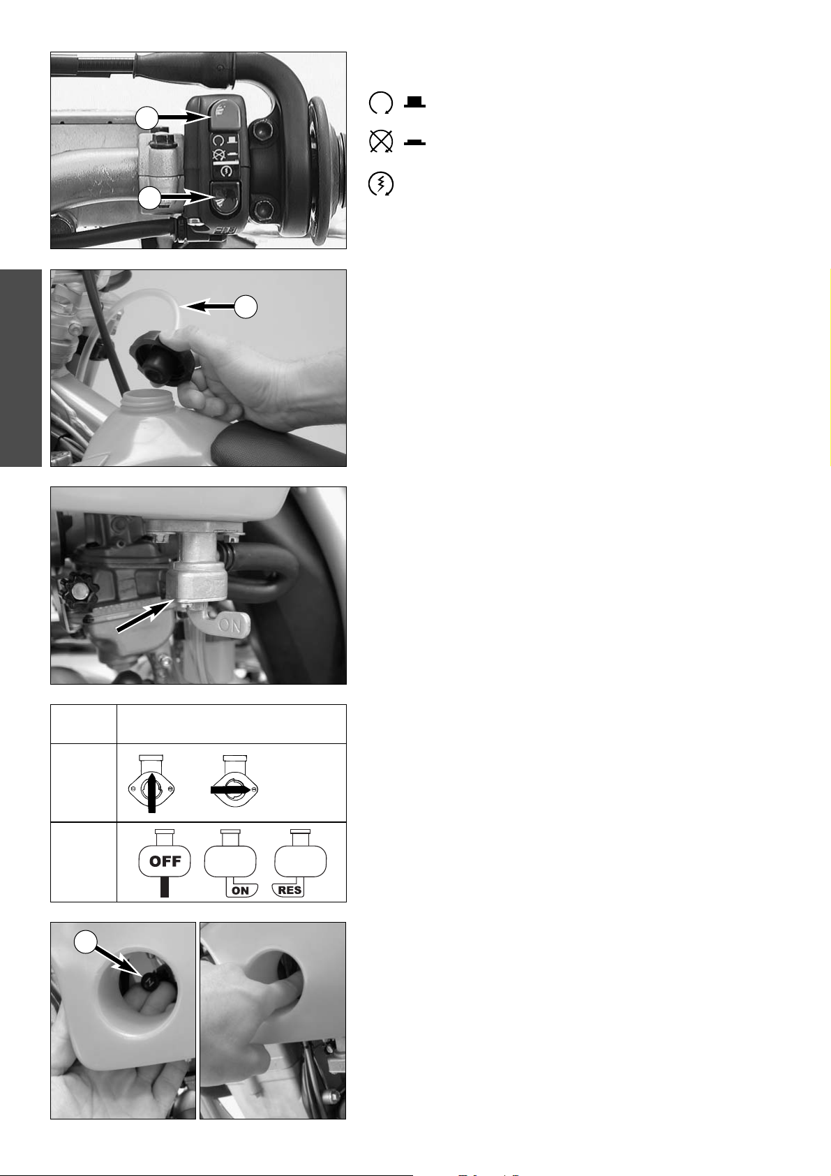
Compression damping of shock absorber (MXC, EXC)
The compression damping (during compression) can be adjusted for the
MXC and EXC shock absorbers (Mono Compression Control).
The degree of damping can be adjusted by turning adjusting screw
1 with
a screwdriver. Turning in a clockwise direction will increase the damping,
turning in a counterclockwise direction will decrease the damping.
STANDARD ADJUSTMENT:
– turn the adjusting screw clockwise to the stop.
– then turn the adjusting screw counterclockwise, counting the number of
clicks that corresponds to the respective type of shock absorber.
Type White Power 1218X761 ..............17 clicks
WARNING
T
HE DAMPING UNIT OF THE SHOCK ABSORBER IS FILLED WITH HIGH-COMPRESSION
NITROGEN
. NEVER TRY TO TAKE THE SHOCK ABSORBER APART OR TO DO ANY MAINTE
-
NANCE WORK YOURSELF. SEVERE INJURIES COULD BE THE RESULT.
NEVER UNSCREW THE BLACK SCREW CONNECTION 2 (24MM).
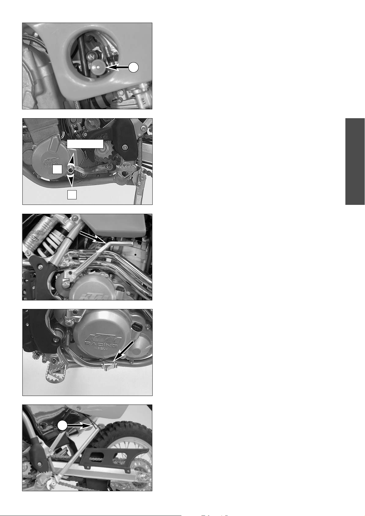
Rebound damping of shock absorber (SX, MXC, EXC)
By using the adjusting screw 3, the degree of damping of the rebound can
be adjusted. Turn the knob to the right side to increase damping, turn it to
the left side to reduce damping during rebounding.
STANDARD ADJUSTMENT:
– turn the adjusting screw clockwise to the stop.
– then turn the adjusting screw counterclockwise, counting the number of
clicks that corresponds to the respective type of shock absorber.
Type White Power 1218X760 ..............26 clicks
Type White Power 1218X761 ..............26 clicks
WARNING
T
HE DAMPING UNIT OF THE SHOCK ABSORBER IS FILLED WITH HIGH
-COMPRESSION
NITROGEN
. NEVER TRY TO TAKE THE SHOCK ABSORBER APART OR TO DO ANY MAINTE-
NANCE WORK YOURSELF. SEVERE INJURIES COULD BE THE RESULT.
NEVER UNSCREW THE BLACK SCREW CONNECTION 4 (15MM).
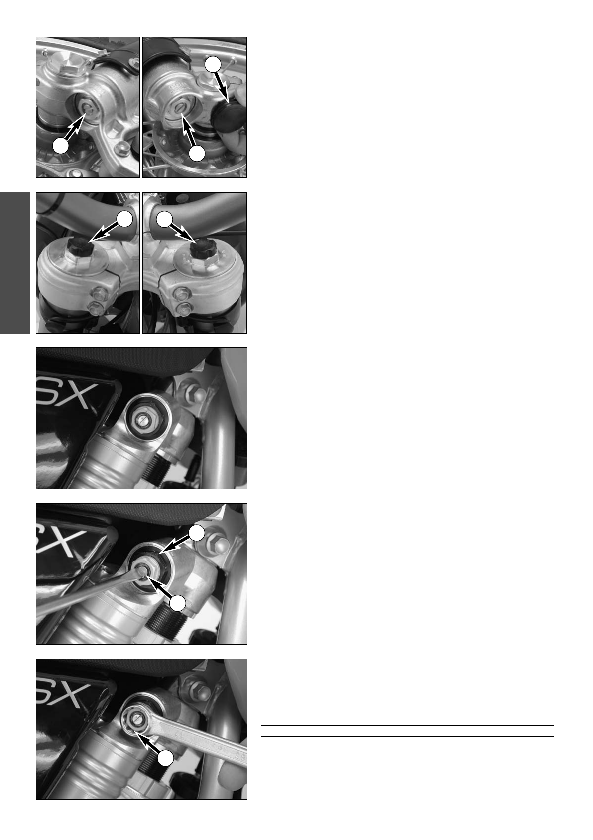
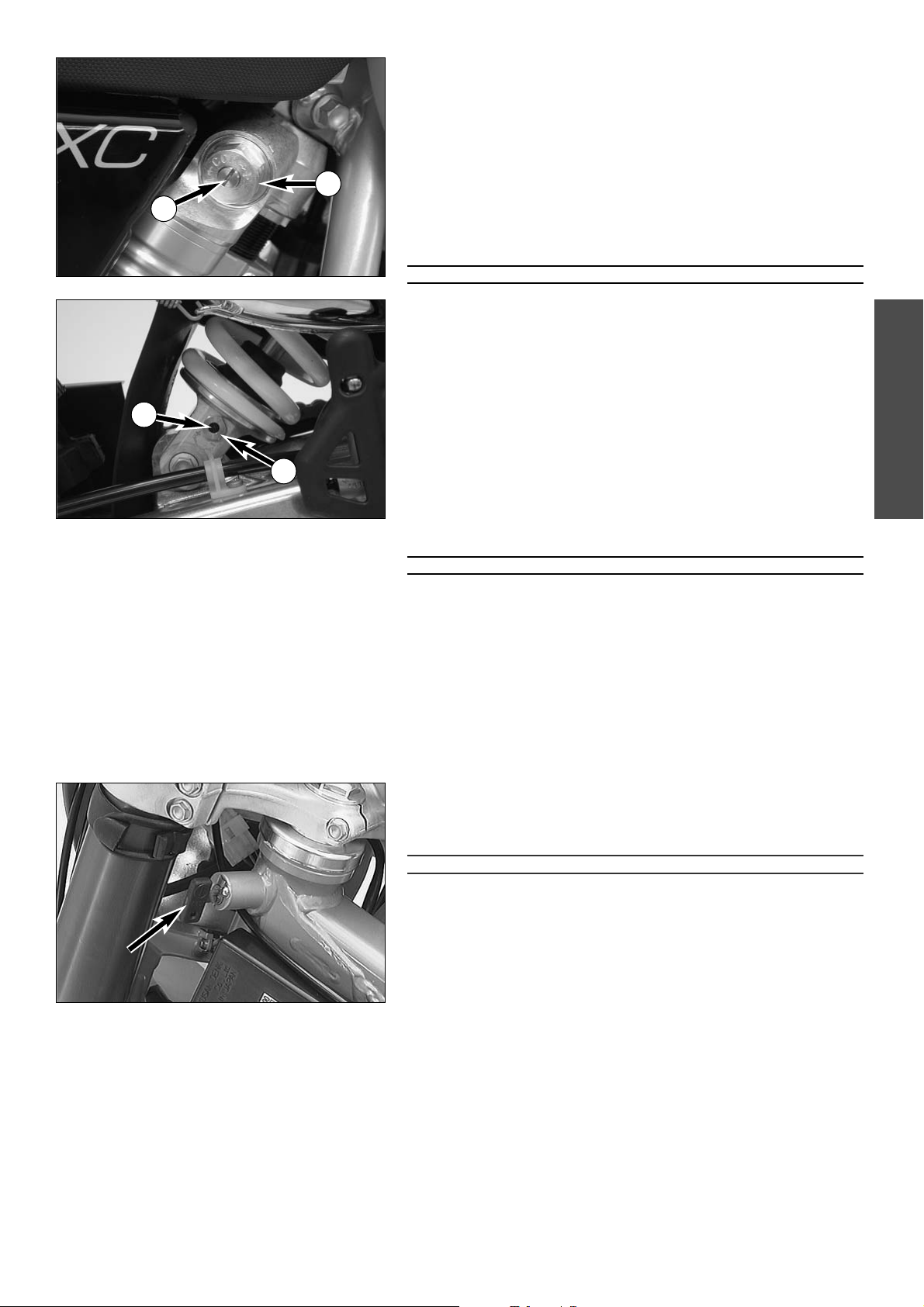
Steering lock
The handlebar can be locked by means of the lock located on the steering
head. To lock it, turn handlebar all the way to the right, insert key, turn it to
left, press it in, turn it to right, and remove it.
!
CAUTION
!
N
EVER LEAVE THE KEY INSERTED IN THE STEERING LOCK. IF YOU TURN THE HANDLEBAR
TO THE LEFT THE KEY COULD GET DAMAGED
.
1
2
3
4

ENGLISH
16
WARNING
–W
EAR SUITABLE CLOTHING WHEN DRIVING A MOTORCYCLE. CLEVER
KTM DRIVERS ALWAYS WEAR A HELMET, BOOTS, GLOVES AND A
JACKET
, REGARDLESS OF WHETHER DRIVING ALL DAY OR JUST FOR A
SHORT TRIP
. THE PROTECTIVE CLOTHING SHOULD BE BRIGHTLY COL-
ORED SO THAT OTHER VEHICLES CAN SEE YOU AS EARLY AS POSSIBLE.
–A
LWAYS TURN ON THE LIGHT TO MAKE SURE THAT OTHER DRIVERS
BECOME AWARE OF YOU AS EARLY AS POSSIBLE
.
–D
ONOT DRIVE AFTER HAVING CONSUMED ALCOHOL.
–O
NLY USE ACCESSORIES RECOMMENDED BY KTM. FOR EXAMPLE,
FRONT PANELLING CAN IMPAIR THE DRIVING PROPERTIES OF THE
MOTORCYCLE
. CASES, EXTRA TANKS, ETC. CAN ALTER THE WEIGHT
DISTRIBUTION AND THUS ALSO IMPAIR THE VEHICLES DRIVING
PROPERTIES
.
–T
HE FRONT AND REAR WHEEL MAY ONLY BE FITTED WITH TIRES THAT
HAVE THE SAME PROFILE TYPE
.
–
B
E SURE TO CHECK THE SPOKE TENSION AFTER
30
MINUTES
'
RUNNING
TIME
. T
HE SPOKE TENSION WILL DECREASE QUICKLY ON NEW WHEELS
.
I
F YOU CONTINUE TO DRIVE WITH LOOSE SPOKES
,
THE SPOKES MAY
CRACK AND LEAD TO UNSTABLE HANDLING
(
SEE
"C
HECKING THE SPOKE
TENSION
").
–THE RACING MODELS ARE DESIGNED AND DIMENSIONED FOR 1 PER-
SON ONLY. NEVER TAKE ANOTHER RIDER ALONG.
–O
BSERVE THE TRAFFIC REGULATIONS, DRIVE DEFENSIVELY AND TRY TO
LOOK AHEAD AS FAR AS POSSIBLE SO THAT ANY HAZARDS CAN BE
RECOGNIZED AS EARLY AS POSSIBLE
.
–A
DJUST YOUR DRIVING SPEED ACCORDING TO THE CONDITIONS AND
YOUR DRIVING SKILLS
.
–D
RIVE CAREFULLY ON UNKNOWN ROADS OR ON UNFAMILIAR TRIALS.
–W
HEN DRIVING OFF-ROAD, ALWAYS HAVE A FRIEND ON A SECOND
MOTORCYCLE TO KEEP YOU COMPANY
, SO THAT YOU CAN HELP EACH
OTHER SHOULD DIFFICULTIES ARISE
.
–R
EPLACE THE HELMET VISOR OR GOGGLE LENS WHEN SCRATCHED OR
DAMAGED
. IF BRIGHT LIGHT SHINES THROUGH A SCRATCHED VISOR OR
LENS
, THE OPERATOR WILL BE BLINDED.
–N
EVER LEAVE YOUR MOTORCYCLE WITHOUT SUPERVISION IF THE
ENGINE IS RUNNING
.
WARNING
–THE SX MODELS ARE NOT APPROVED FOR USE ON PUBLIC ROADS AND
FREEWAYS
.
–W
HEN RIDING YOUR MOTORCYCLE, PLEASE BEAR IN MIND THAT
OTHER PEOPLE MAY FEEL MOLESTED BY EXCESSIVE NOISE
.
Instructions for initial operation
– Verify that your KTM dealer performed the PREPARATION
OF VEHICLE jobs (see Customer Service Manual).
– Read these operating instructions carefully before your first
ride.
– Familiarize yourself with the operating elements.
– Set the clutch lever, the handbrake lever, and the footbrake
pedal to the positions that are most convenient for you.
– Get used to handling the motorcycle on an empty parking
lot or open space, before starting on a longer drive. Also try
to drive as slowly as possible and in a standing position, to
improve your feeling for the vehicle.
– Do not drive along off-road tracks which go beyond your
abitily and experience.
– Hold the handlebars with both hands and leave your feet on
the foot rests while driving.
– Remove your foot from the foot brake lever when you are
not braking. If the foot brake lever is not released the brake
pads rub continuously and the braking system is over-
heated.
– Do not make any alterations to the motorcycle and always
use ORIGINAL KTM SPARE PARTS. Spare parts from other
manufacturers can impair the safety of the motorcycle.
– Motorcycles are sensitive to alterations in the distribution of
weight. If you are taking luggage with you, this should be
secured as close as possible to the middle of the vehicle; dis-
tribute the weight evenly between the front and rear wheel.
Never exceed the maximum permissible laden weight and
the axle weights. The maximum permissible laden weight is
comprised of the following components:
– Motorcycle ready for operation and tank full
– Luggage
– Driver with protective clothing and helmet.
– Pay attention to the running-in procedure.
Running in the Racing models
Even very precisely machined sections of engine components
have rougher surfaces than components which have been slid-
ing across one another for quite some time. Therefore, every
engine needs to be broken in.
For this reason, do not load the engine more than 50% of its
capacity during the first 3 operating hours. Besides, the engine
speed must not exceed 7000 rpm. Avoid going full-throttle!
In the following 12 operating hours, you may load the engine
up to 75% of its capacity. Use the motorcycle on various types
of terrain (road, easy off-road trails).
!
CAUTION
!
T
HE 250/450/525 SX/MXC/EXC RACING MODELS WERE UNCOM-
PROMISINGLY DESIGNED FOR OFF-ROAD COMPETITION PURPOSES ONLY.
E
VEN THOUGH THE EXC MODELS ARE APPROVED FOR USE ON PUBLIC
ROADS
, THEIR USE ON ROADS IS RECOMMENDED ONLY TO A VERY
LIMITED EXTENT
. AVOID EXTENDED ON-ROAD RIDES AT FULL THROTTLE.
GENERAL TIPS AND WARNINGS FOR STARTING THE MOTORCYCLE
ENGLISH
17
DRIVING INSTRUCTIONS
Check the following before each start
When you start off, the motorcycle must be in perfect technical condition.
For safety reasons, you should make a habit of performing an overall check
of your motorcycle before each start.
The following checks should be performed:
1 CHECK THE OIL LEVEL
Insufficient oil results in premature wear and consequently to engine
damage.
2 FUEL
Check that there is sufficient fuel in the tank; when closing the filler cap,
check that the tank venting hose is free of kinks.
3 CHAIN
A loose chain can fall from the chain wheels; an extremely worn chain
can tear, and insufficient lubrication can result in unnecessary wear to
the chain and chain wheels. Excessive tensioning of the chain will put
additional load on the components of the secondary drivetrain (chain,
bearings of transmission and rear wheel). Aside from resulting in prema-
ture wear, if worst comes to worst the chain may rupture or the coun-
tershaft of the transmission may break.
4 TIRES
Check for damaged tires. Tires showing cuts or dents must be replaced.
The tread depth must comply with the legal regulations. Also check the
air pressure. Insufficient tread and incorrect air pressure deteriorate the
driving performance.
5 BRAKES
Check correct functioning of the braking system. Check for sufficient
brake fluid in the reservoir. The reservoirs have been designed in such a
way that brake fluid does not need to be refilled even when the brake
pads are worn. If the level of brake fluid falls below the minimum value,
this indicates a leak in the braking system or completely worn out brake
pads. Arrange for the braking system to be checked by a KTM specialist,
as complete failure of the braking system can be avoided.
Also check the state of the brake hose and the thickness of the brake
linings.
Check free travel at the hand brake lever and foot brake lever.
6 CABLES
Check correct setting and easy running of all control cables.
7 COOLING FLUID
Check the level of the cooling fluid when the engine is cold.
8 ELECTRICAL SYSTEM
Check correct functioning of headlamps, tail-lights, brake lights,
indicators, control lamps and horn while the engine is running.
9 LUGGAGE
If you are taking luggage with you, check that this is securely fastened.
A
B
ENGLISH
18
Starting when the engine is cold
1 Open the fuel tap 1.
2 Swing up the side stand or center stand.
3 Put the gear in neutral.
4 Operate the choke
2.
5 Leave throttle closed and kick the kickstarter briskly ALL THE WAY or
actuate the E-starter.
WARNING
–IF YOU WANT TO START THE ENGINE, MAKE SURE THAT YOU ALWAYS PUT ON STURDY
MOTORCYCLE BOOTS IN ORDER TO AVOID INJURIES
. YOU MIGHT SLIP OFF THE KICK-
STARTER, OR THE ENGINE MAY KICK BACK AND PROPEL YOUR FOOT UPWARD WITH
GREAT FORCE
.
–A
LWAYS KICK THE KICKSTARTER BRISKLY ALL THE WAY WITHOUT OPENING THE
THROTTLE
. IF YOU DO NOT KICK HARD ENOUGHT, WITH AN OPEN THROTTLE GRIP,
THE KICK-BACK HAZARD WILL BE HIGHER.
–DO NOT START THE ENGINE AND ALLOW IT TO IDLE IN A CLOSED AREA
. EXHAUST
FUMES ARE POISONOUS AND CAN CAUSE LOSS OF CONSCIOUSNESS AND DEATH
.
A
LWAYS PROVIDE ADEQUATE VENTILATION WHILE THE ENGINE IS RUNNING.
–ALWAYS VERIFY THAT THE TRANSMISSION HAS BEEN SET TO IDLE
(NEUTRAL) BEFORE
ACTUATING THE STARTER BUTTON
. IF YOU START THE MOTORCYCLE WITH A GEAR
ENGAGED
, THE MOTORCYCLE WILL MOVE FORWARD.
!
CAUTION
!
–M
AXIMAL PERIOD FOR CONTINUOUS STARTING: 5 SECONDS. WAIT AT LEAST 5
SECONDS BEFORE TRYING AGAIN.
–D
ON’T RIDE YOUR MOTORCYCLE WITH FULL LOAD AND DON’TREV UP THE ENGINE
WHEN COLD BECAUSE THE PISTON IS WARMING UP FASTER THAN THE WATER COOLED
CYLINDER AND CAN CAUSE ENGINE DAMAGE
.
Starting when the engine is warm
1 Open the fuel tap 1.
2 Swing up the side stand.
3 Put the gear in neutral.
4 Leave throttle closed and kick the kickstarter briskly ALL THE WAY or
actuate the E-starter.
What to do when the engine is “flooded”
In the event of a fall, more fuel than necessary may get into the engine. In
order to "pump the engine free", pull the hand decompression lever, fully
rev up the engine, actuate the kickstarter 5 to 10 times or actuate the E-
starter 2 times for 5 seconds each. Then, start the engine as described
above.
If the engine fails to start, unscrew the spark plug and dry it.
NOTE:
The carburetor has an accelerator pump. Every time you open the throttle,
fuel will be injected into the intake passage. When starting, be sure that you
open the throttle completely only once.
Starting off
Pull the clutch lever. Put the engine into first gear, slowly release the clutch
lever and open the throttle at the same time.
WARNING
BEFORE YOU START OFF, CHECK THAT THE SIDE STAND HAS BEEN SWUNG UP FULLY. IF
THE STAND DRAGS ON THE GROUND
, THE MOTORCYCLE CAN GO OUT OF
CONTROL
.
Shifting/Riding
You are now in first gear, refered to as the drive or uphill gear. Depending
on the conditions (traffic, hill size, etc.), you can shift to a higher gear. Close
throttle, at the same time pull clutch lever in and shift to the next higher
gear. Let clutch lever go again and accelerate. If you turned on the choke,
make sure you turn it off again as soon as engine is warm.
When you reach full speed through opening the throttle all the way, turn
throttle back to 3/4; the speed hardly decreases although the engine will
use less gas. Only give as much gas as the engine can handle. Through
quick and high revving of the throttle, the fuel usage increases.
By shifting down, use the brakes if necessary and close the throttle at the
same time. Pull the clutch lever and shift down to the next gear. Let clutch
lever go slowly and open the throttle or shift down again.
1
2
 Loading...