


 Loading...
Reference Manual
300560EN, Rev AA
May 2011
Rosemount 2230
Graphical Field Display
www.rosemount-tg.com

Reference Manual
300560EN, Rev AA
May 2011
Rosemount 2230
Rosemount 2230
Graphical Field Display
NOTICE
Read this manual before working with the product. For personal and system safety, and for optimum product performance, make sure you thoroughly understand the contents before installing, using, or maintaining this product.
For equipment service or support needs, contact your local Emerson Process Management/Rosemount Tank Gauging representative.
Spare Parts
Any substitution of non-recognized spare parts may jeopardize safety. Repair, e.g. substitution of components etc, may also jeopardize safety and is under no circumstances allowed.
Rosemount Tank Radar AB will not take any responsibility for faults, accidents, etc caused by non-recognized spare parts or any repair which is not made by
Rosemount Tank Radar AB.
Cover Photo: 2230_coverphoto_2.jpg
www.rosemount-tg.com

Reference Manual
300560EN, Rev AA
May 2011
Rosemount 2230
Table of Contents
SECTION 1
Introduction
SECTION 2
Overview
SECTION 3
Installation
SECTION 4
Configuration and
Operation
1.1 Safety Messages . . . . . . . . . . . . . . . . . . . . . . . . . . . . . . . . . . . . 1-1 1.2 Symbols. . . . . . . . . . . . . . . . . . . . . . . . . . . . . . . . . . . . . . . . . . . 1-2 1.3 Manual Overview. . . . . . . . . . . . . . . . . . . . . . . . . . . . . . . . . . . . 1-3 1.4 Technical Documentation . . . . . . . . . . . . . . . . . . . . . . . . . . . . . 1-4 1.5 Product Recycling/ Disposal . . . . . . . . . . . . . . . . . . . . . . . . . . . 1-5 1.6 Packing Material . . . . . . . . . . . . . . . . . . . . . . . . . . . . . . . . . . . . 1-5
1.6.1 Reuse and Recycling . . . . . . . . . . . . . . . . . . . . . . . . . 1-5 1.6.2 Energy recovery . . . . . . . . . . . . . . . . . . . . . . . . . . . . . 1-5
2.1 Introduction . . . . . . . . . . . . . . . . . . . . . . . . . . . . . . . . . . . . . . . . 2-1 2.2 2230 Components . . . . . . . . . . . . . . . . . . . . . . . . . . . . . . . . . . . 2-2 2.3 System Overview. . . . . . . . . . . . . . . . . . . . . . . . . . . . . . . . . . . . 2-3 2.3.1 Raptor System Start-up . . . . . . . . . . . . . . . . . . . . . . . 2-7 2.4 Installation procedure . . . . . . . . . . . . . . . . . . . . . . . . . . . . . . . . 2-8
3.1 Safety Messages . . . . . . . . . . . . . . . . . . . . . . . . . . . . . . . . . . . . 3-1 3.2 Mechanical Installation . . . . . . . . . . . . . . . . . . . . . . . . . . . . . . . 3-2 3.2.1 Installation Considerations . . . . . . . . . . . . . . . . . . . . . 3-2 3.2.2 Mounting the Graphical Display . . . . . . . . . . . . . . . . . 3-3
3.3 Electrical Installation . . . . . . . . . . . . . . . . . . . . . . . . . . . . . . . . . 3-6 3.3.1 Cable/Conduit Entries . . . . . . . . . . . . . . . . . . . . . . . . 3-6 3.3.2 Grounding . . . . . . . . . . . . . . . . . . . . . . . . . . . . . . . . . 3-6 3.3.3 Cable Selection for the Tankbus . . . . . . . . . . . . . . . . 3-7 3.3.4 Hazardous Areas . . . . . . . . . . . . . . . . . . . . . . . . . . . . 3-7 3.3.5 Power Requirements . . . . . . . . . . . . . . . . . . . . . . . . . 3-7 3.3.6 The Tankbus . . . . . . . . . . . . . . . . . . . . . . . . . . . . . . . 3-8 3.3.7 Typical installations . . . . . . . . . . . . . . . . . . . . . . . . . . 3-9 3.3.8 Wiring . . . . . . . . . . . . . . . . . . . . . . . . . . . . . . . . . . . . 3-10
3.4 LED signals and Reset Button. . . . . . . . . . . . . . . . . . . . . . . . . 3-13 3.5 Switches . . . . . . . . . . . . . . . . . . . . . . . . . . . . . . . . . . . . . . . . . 3-14 3.5.1 DIP Switches . . . . . . . . . . . . . . . . . . . . . . . . . . . . . . 3-14 3.6 Ambient Temperature . . . . . . . . . . . . . . . . . . . . . . . . . . . . . . . 3-14
4.1 Safety Messages . . . . . . . . . . . . . . . . . . . . . . . . . . . . . . . . . . . . 4-1 4.2 Introduction . . . . . . . . . . . . . . . . . . . . . . . . . . . . . . . . . . . . . . . . 4-2 4.2.1 The 2230 Graphical Field Display . . . . . . . . . . . . . . . 4-2 4.2.2 Activity and Alarm Indication . . . . . . . . . . . . . . . . . . . 4-3
4.3 Menu Tree . . . . . . . . . . . . . . . . . . . . . . . . . . . . . . . . . . . . . . . . . 4-4 4.4 The Main Menu . . . . . . . . . . . . . . . . . . . . . . . . . . . . . . . . . . . . . 4-5 4.5 The Select View Menu. . . . . . . . . . . . . . . . . . . . . . . . . . . . . . . . 4-6 4.6 The Options Menu . . . . . . . . . . . . . . . . . . . . . . . . . . . . . . . . . . . 4-7 4.6.1 Variables . . . . . . . . . . . . . . . . . . . . . . . . . . . . . . . . . . 4-8 4.6.2 Select Tanks . . . . . . . . . . . . . . . . . . . . . . . . . . . . . . 4-10 4.6.3 Units for Display . . . . . . . . . . . . . . . . . . . . . . . . . . . . 4-11 4.6.4 Toggle Time . . . . . . . . . . . . . . . . . . . . . . . . . . . . . . . 4-13 4.6.5 Language . . . . . . . . . . . . . . . . . . . . . . . . . . . . . . . . . 4-13
Table of Contents |
TOC-1 |

Reference Manual
Rosemount 2230
300560EN, Rev AA
May 2011
SECTION 5
Service and
Troubleshooting
4.7 The Service Menu . . . . . . . . . . . . . . . . . . . . . . . . . . . . . . . . . . 4-14
4.7.1 Status . . . . . . . . . . . . . . . . . . . . . . . . . . . . . . . . . . . . 4-15
4.7.2 Custody Transfer View. . . . . . . . . . . . . . . . . . . . . . . 4-15
4.7.3 LCD Test . . . . . . . . . . . . . . . . . . . . . . . . . . . . . . . . . 4-16
4.7.4 LCD Contrast . . . . . . . . . . . . . . . . . . . . . . . . . . . . . . 4-16
4.7.5 Restart . . . . . . . . . . . . . . . . . . . . . . . . . . . . . . . . . . . 4-17
4.7.6 Factory Settings . . . . . . . . . . . . . . . . . . . . . . . . . . . . 4-17
4.7.7 About . . . . . . . . . . . . . . . . . . . . . . . . . . . . . . . . . . . . 4-18
5.1 Safety Messages . . . . . . . . . . . . . . . . . . . . . . . . . . . . . . . . . . . . 5-1
5.2 Service. . . . . . . . . . . . . . . . . . . . . . . . . . . . . . . . . . . . . . . . . . . . 5-2
5.2.1 Status Information . . . . . . . . . . . . . . . . . . . . . . . . . . . 5-2
5.2.2 Viewing Input and Holding Registers . . . . . . . . . . . . . 5-3
5.2.3 Restarting the 2230 Display . . . . . . . . . . . . . . . . . . . . 5-5
5.2.4 Device Error Signals . . . . . . . . . . . . . . . . . . . . . . . . . 5-6
5.3 Troubleshooting. . . . . . . . . . . . . . . . . . . . . . . . . . . . . . . . . . . . . 5-7
5.3.1 Device Errors . . . . . . . . . . . . . . . . . . . . . . . . . . . . . . . 5-9
5.3.2 Device Warnings . . . . . . . . . . . . . . . . . . . . . . . . . . . 5-10
5.3.3 Status Information . . . . . . . . . . . . . . . . . . . . . . . . . . 5-11
APPENDIX A
Reference Data
APPENDIX B
Product Certifications
A.1 Specifications . . . . . . . . . . . . . . . . . . . . . . . . . . . . . . . . . . . . . .A-1 A.2 Dimensional drawings . . . . . . . . . . . . . . . . . . . . . . . . . . . . . . . .A-3 A.3 Ordering Information . . . . . . . . . . . . . . . . . . . . . . . . . . . . . . . . .A-4
B.1 Safety messages . . . . . . . . . . . . . . . . . . . . . . . . . . . . . . . . . . . .B-1 B.2 EU Conformity . . . . . . . . . . . . . . . . . . . . . . . . . . . . . . . . . . . . . .B-2 B.3 Hazardous Locations Certifications . . . . . . . . . . . . . . . . . . . . . .B-3 B.3.1 Factory Mutual US Approvals . . . . . . . . . . . . . . . . . .B-3 B.3.2 Factory Mutual Canadian Approvals . . . . . . . . . . . . .B-4 B.3.3 European ATEX Directive Information . . . . . . . . . . . .B-5 B.3.4 IECEx Approval . . . . . . . . . . . . . . . . . . . . . . . . . . . . .B-7 B.4 Approval Drawings . . . . . . . . . . . . . . . . . . . . . . . . . . . . . . . . . .B-8
TOC-2 |
Table of Contents |

Reference Manual
300560EN, Rev AA
May 2011
Rosemount 2230
Section 1 |
Introduction |
|
||
|
|
|
|
|
|
1.1 |
Safety Messages . . . . . . . . . . . . . . . . . . . . . . . . . . . . |
page 1-1 |
|
|
1.2 |
Symbols . . . . . . . . . . . . . . . . . . . . . . . . . . . . . . . . . . . |
page 1-2 |
|
|
1.3 |
Manual Overview . . . . . . . . . . . . . . . . . . . . . . . . . . . |
page 1-3 |
|
|
1.4 |
Technical Documentation . . . . . . . . . . . . . . . . . . . . |
page 1-4 |
|
|
1.5 |
Product Recycling/ Disposal . . . . . . . . . . . . . . . . . . |
page 1-5 |
|
|
|
1.6 |
Packing Material . . . . . . . . . . . . . . . . . . . . . . . . . . . . |
page 1-5 |
1.1SAFETY MESSAGES
Procedures and instructions in this manual may require special precautions to ensure the safety of the personnel performing the operations. Information that raises potential safety issues is indicated by a warning symbol (  ). Refer to the safety messages listed at the beginning of each section before performing an operation preceded by this symbol.
Failure to follow these installation guidelines could result in death or serious injury:
•Make sure only qualified personnel perform the installation.
•Use the equipment only as specified in this manual. Failure to do so may impair the protection provided by the equipment.
Explosions could result in death or serious injury:
•Verify that the operating environment of the transmitter is consistent with the appropriate hazardous locations certifications.
•Before connecting a hand held communicator in an explosive atmosphere, make sure the instruments in the loop are installed in accordance with intrinsically safe or non-incendive field wiring practices.
•Do not remove the cover in explosive atmospheres when the circuit is alive.
•Substitution of components may impair Intrinsic Safety.
•To prevent ignition of flammable or combustible atmospheres, disconnect power before servicing.
Electrical shock could cause death or serious injury.
•Use extreme caution when making contact with the leads and terminals.
Any substitution of non-recognized parts may jeopardize safety. Repair, e.g. substitution of components etc., may also jeopardize safety and is under no circumstances allowed.
www.rosemount-tg.com
Reference Manual
Rosemount 2230
300560EN, Rev AA
May 2011
1.2 SYMBOLS
The CE marking symbolizes the conformity of the product with the applicable European Community Directives.
The EC-Type Examination Certificate is a statement of a Notified Certification Body declaring that this product meets the Essential Health and Safety Requirements of the ATEX directive.
The FM APPROVED Mark indicates that the equipment is approved by FM Approvals according to applicable Approval Standards and is applicable for installation in hazardous locations.
Protective Earth.
Ground.
External cabling must be approved for use in min. 75°C.
1-2 |
Section 1. Introduction |

Reference Manual
300560EN, Rev AA
May 2011
Rosemount 2230
1.3MANUAL OVERVIEW
Section 1:Introduction
•Manual overview
•Product recycling/disposal
•Packing material
Section 2: Overview
•Introduction
•2230 Components
•System Overview
•Getting started
•Installation Procedure
Section 3: Installation
•Mounting considerations
•Mechanical installation
•Electrical installation
•LED signals and Reset button
•Switches
Section 4: Configuration
•Menu tree
•Select View menu
•Options menu
•Service menu
Section 5: Service and troubleshooting
•Service
•Troubleshooting
Appendix A: Reference data
•Specifications
•Dimensional Drawings
•Ordering Information
Appendix B: Product certifications
•EU Conformity
•FM US Approvals
•FM Canadian Approvals
•European ATEX Directive Information
•IECEx Approval
Section 1. Introduction |
1-3 |

Reference Manual
Rosemount 2230
300560EN, Rev AA
May 2011
1.4TECHNICAL DOCUMENTATION
The Raptor System includes the following documents:
•Raptor Technical Description (704010EN)
•Rosemount 5900S Reference Manual (300520EN)
•Rosemount 2410 Reference Manual (300530EN)
•Rosemount 2240S Reference Manual (300550EN)
•Rosemount 2230 Reference Manual (300560EN)
•Raptor System Configuration Manual (300510EN)
•Rosemount 5300 Product Data Sheet (00813-0100-4530)
•Rosemount 5400 Product Data Sheet (00813-0100-4026)
•Rosemount 5300 Series Reference Manual (00809-0100-4530)
•Rosemount 5400 Series Reference Manual (00809-0100-4026)
•Rosemount TankMaster WinOpi Reference Manual (303028EN)
•Rosemount Raptor Installation Drawings
1-4 |
Section 1. Introduction |
Reference Manual
300560EN, Rev AA
May 2011
Rosemount 2230
1.5PRODUCT RECYCLING/ DISPOSAL
Recycling of equipment and packaging should be taken into consideration and disposed of in accordance with local and national legislation/regulations.
The label below is put on Rosemount Tank Gauging products as a recommendation to customers if scrapping is considered.
Recycling or disposal should be done following instructions for correct separation of materials when breaking up the units.
Figure 1-1. A green label is placed on the housing of the level gauge
|
|
AR |
|
|
|
|
|
|
P |
A |
|
|
|
||
E |
|
|
T |
|
|
|
|
|
|
E |
|
|
|||
S |
|
|
|
|
|
|
|
T |
|
|
|
|
|
|
C |
S |
|
|
|
|
|
T |
I |
E |
|
|
|
|
S |
||
|
|
|
|
|
|||
E |
|
|
|
|
|
||
|
|
A |
|
|
|||
|
L |
|
|
|
|
||
|
|
& PL |
|
|
|
||
1.6PACKING MATERIAL
1.6.1Reuse and Recycling
Rosemount Tank Radar AB is fully certified according to ISO 14001 environmental standards. By recycling the corrugated paperboard, or wooden boxes, used for shipping our products you can contribute to take care of the environment.
Experience has shown that wooden boxes can be used several times for various purposes. After careful disassembly the wooden parts may be reused. Metal waste may be converted.
1.6.2Energy recovery Products which have served their time may be divided into wood and metal
components and the wood can be used as fuel in sufficient ovens.
Due to its low moisture content (approximately 7%) this fuel has a higher calorific value than ordinary wood fuel (moisture content approximately 20%).
When burning interior plywood the nitrogen in the adhesives may increase emissions of nitrogen oxides to the air 3-4 times more than when burning bark and splinter.
NOTE!
Landfill is not a recycling option and should be avoided.
Section 1. Introduction |
1-5 |

Reference Manual
Rosemount 2230
300560EN, Rev AA
May 2011
1-6 |
Section 1. Introduction |
Reference Manual
300560EN, Rev AA
May 2011
Rosemount 2230
Section 2 |
Overview |
|
||
|
|
|
|
|
|
2.1 |
Introduction . . . . . . . . . . . . . . . . . . . . . . . . . . . . . . . . |
page 2-1 |
|
|
2.2 |
2230 Components . . . . . . . . . . . . . . . . . . . . . . . . . . . |
page 2-2 |
|
|
2.3 |
System Overview . . . . . . . . . . . . . . . . . . . . . . . . . . . |
page 2-3 |
|
|
|
2.4 |
Installation procedure . . . . . . . . . . . . . . . . . . . . . . . |
page 2-8 |
2.1 INTRODUCTION
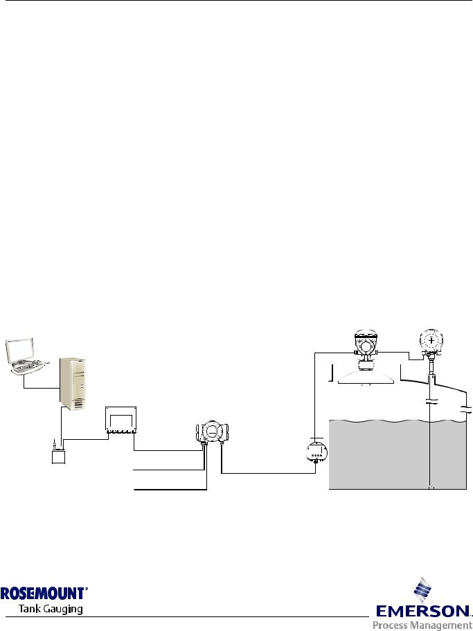
The Rosemount 2230 Graphical Field Display presents inventory tank gauging data such as level, temperature, and pressure. The 2230 communicates with the Rosemount 2410 Tank Hub via the intrinsically safe 2-wire Tankbus(1).
A 2230 connected to the multiple tank version of the 2410 allows you to view data from several tanks. It is possible to configure presentation of measurement variables for each tank individually.
The four softkeys at the front of the 2230 allow you to navigate through the different menus and provides all tank data, directly on the field.
Data from a group of tanks is buffered by a 2160 Field Communication Unit (FCU), and is distributed via the Group Bus to a TankMaster PC, or a host system, whenever the FCU receives a request for data. In case no FCU is included in the system, the 2410 Tank Hub can communicate directly with the host computer.
Figure 2-1. System integration
5900S Radar |
2240S Temperature |
Level Gauge |
Transmitter |
TankMaster
2160 Field
Communication Unit
|
|
|
|
|
|
|
|
|
|
2410 Tank Hub |
|
|
||||||
|
|
|
Group Bus |
|
|
|
|
|
|
|
|
|
2230 Display |
|
||||
|
|
|
|
|
|
|
|
|
|
|
|
|
|
|
|
|
||
|
|
|
|
|
|
|
|
|
|
|
|
|
|
|
|
|
||
|
|
|
|
|
|
|
|
|
|
|
|
|
||||||
|
|
|
|
|
|
|
|
|
||||||||||
|
|
|||||||||||||||||
|
|
|
|
|
|
|
|
|
|
Primary Bus |
|
|
|
|
|
|
|
|
|
|
|
|
|
|
|
|
|
|
|
|
|
|
|
|
|
|
|
|
|
|
||||||||||||||||
|
|
|
|
|
||||||||||||||
|
|
|
|
|
|
|
|
|
|
Secondary bus |
Tankbus |
|
||||||
|
|
|
|
|
|
|
|
|
|
|
||||||||
|
|
|
|
|
|
|
|
|
|
|
||||||||
|
|
|
|
|
|
|
|
|
|
|
||||||||
Modem |
|
|
||||||||||||||||
|
|
|
|
|
|
|
|
|
|
Relay outputs |
|
|
||||||
(1)The intrinsically safe Tankbus complies with the FISCO FOUNDATION™ fieldbus standard. See reference document IEC/TS 60079-27.
www.rosemount-tg.com
Reference Manual
Rosemount 2230
300560EN, Rev AA
May 2011
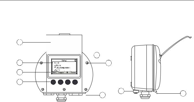
2.2 2230 COMPONENTS
Figure 2-2. Rosemount 2230 components
1.Weather protection lid(1)
2.Display
3.Menu
4.Soft keys
5.Activity indicator
6.Cover screw
7.Cable entries: two M20 x 1.5 and one M25 x 1.5 (optional: ½ - 14 NPT and ¾ - 14 NPT adapters)
8.Ground screw
9.Locking spring for weather protection
(1)It is recommended that the lid is closed whenever possible to protect the LCD from exposure by ultraviolet radiation from the sun.
2-2 |
Section 2. Overview |

Reference Manual
300560EN, Rev AA
May 2011
Rosemount 2230
2.3SYSTEM OVERVIEW
Raptor is a state-of-the art inventory and custody transfer radar tank level gauging system. It is developed for a wide range of applications at refineries, tank farms and fuel depots, and fulfills the highest requirements on performance and safety.
The field devices on the tank communicate over the intrinsically safe Tankbus. The Tankbus is based on a standardized fieldbus, the FISCO(1) FOUNDATION™ fieldbus, and allows integration of any device supporting that protocol. By utilizing a bus powered 2-wire intrinsically safe fieldbus the power consumption is minimized. The standardized fieldbus also enables integration of other vendors’ equipment on the tank.
The Raptor product portfolio includes a wide range of components to build small or large customized tank gauging systems. The system includes various devices, such as radar level gauges, temperature transmitters, and pressure transmitters for complete inventory control. Such systems are easily expanded thanks to the modular design.
Raptor is a versatile system that is compatible with and can emulate all major tank gauging systems. Moreover, the well-proven emulation capability enables step-by-step modernization of a tank farm, from level gauges to control room solutions.
It is possible to replace old mechanical or servo gauges with modern Raptor gauges, without replacing the control system or field cabling. It is further possible to replace old HMI/SCADA-systems and field communication devices without replacing the old gauges.
There is a distributed intelligence in the various system units which continuously collect and process measurement data and status information. When a request for information is received an immediate response is sent with updated information.
The flexible Raptor system supports several combinations to achieve redundancy, from control room to the different field devices. Redundant network configuration can be achieved at all levels by doubling each unit and using multiple control room work stations.
(1)See documents IEC 61158-2 and IEC/TS 60079-27
Section 2. Overview |
2-3 |

Reference Manual
Rosemount 2230
300560EN, Rev AA
May 2011
Figure 2-3. Raptor system architecture
|
5900S Radar |
2240S Temperature |
||||||||||
NON-HAZARDOUS AREA HAZARDOUS AREA |
Level Gauge |
Transmitter |
||||||||||
|
|
|
|
|
|
|
|
|
|
|
|
|
|
|
|
|
|
|
|
|
|
|
|
|
|
|
|
|
|
|
|
|
|
|
|
|
|
|
|
|
|
|
|
|
|
|
|
|
|
|
|
|
|
|
|
|
|
|
|
|
|
|
|
|
OPERATIONAL CONTROL CUSTODY TRANSFER / INVENTORY TANK GAUGING
TankMaster PC
2230 Display
2410 Tank Hub
3051S
Pressure
Transmitter
|
|
|
|
|
|
|
|
|
|
|
|
|
|
|
|
|
|
|
|
|
|
|
|
|
|
|
|
|
|
|
|
|
|
|
|
|
Tankbus |
|
|
|
|
|
|
|
|
|
|
|
|
|
|
|
|
|
|
|
|
|
|
|
|
|
|
|
|
|
|
|
|
|
|
|
|
|
|
|
|
|
|
|
|
|
|
|
|
|
|
|
|
|
|
|
|||||||||||||||
|
|
|
|
|
|
|
|
|
|
|
|
|
2160 Field |
|
|
|
|
|
|
|
|
|
|
|
|
|
|
|
|
|
|
|
|
|
|
|
|
|
|
|
|
|
|
|
|
|
|
|
|
|
|
|
|
5900S Radar |
|||||||||||||||||||||||||||||||||||||||||||||||||||||
2180 Field |
|
|
|
|
|
Communication Unit |
|
|
|
|
|
|
|
|
|
|
|
||||||||||||||||||||||||||||||||||||||||||||||||||||||||||||||||||||||||||||||||||||||||||
|
|
|
|
|
|
|
|
|
|
|
|
|
|
|
|
|
|
|
|
|
|
|
|
|
|
|
|
|
|
|
|
|
|
|
|
|
|
|
|
|
|
|
|
|
|
|
|
|
|
|
|
|
|
|
|
Level Gauge |
|||||||||||||||||||||||||||||||||||||||||||||||||||
Bus Modem |
|
|
|
|
|
|
|
|
|
|
|
|
|
|
|
|
|
|
|
|
|
|
|
|
|
|
|
|
|
|
|
|
|
|
|
|
|
|
|
|
|
|
|
|
|
|
|
|
|
|
|
|
|
|
|
|
|
|
|
|
|
|
|
|
|
|
|
|
|
|
|
|
|
|
|
|
|
|
|
|
|
|
|
|
|
|
|
|
|
|
|
|
|
|
|
|
|
|
|
|
|||||||
|
|
|
|
|
|
|
|
|
|
|
|
|
|
|
|
|
|
|
|
|
|
|
|
|
|
|
|
|
|
|
|
|
|
|
|
|
|
|
|
|
|
|
|
|
|
|
|
|
|
|
|
|
|
|
|
|
|
|
|
|
|
|
|
|
|
|
|
|
|
|
|
|
|
|
|
|
|
|
|
|
|
|
|
|
|
|
|
|
|
|
|
|
|
|
|
|
|
|
|
|
|
|
|
|
|
|
|
|
|
|
|
|
|
|
|
|
|
|
|
|
|
|
|
|
|
|
|
|
|
|
|
|
|
|
|
|
|
|
|
|
|
|
|
|
|
|
|
|
|
|
|
|
|
|
|
|
|
|
|
|
|
|
|
|
|
|
|
|
|
|
|
|
|
|
|
|
|
|
|
|
|
|
|
|
|
|
|
|
|
|
|
|
|
|
|
|
|
|
|
|
|
|
|
|
|
|
|
|
|
|
|
|
|
|
|
|
|
|
|
|
|
|
|
|
|
|
|
|
|
|
|
|
|
|
|
|
|
|
|
|
|
|
|
|
|
|
|
|
|
|
|
|
|
|
|
|
|
|
|
|
|
|
|
|
|
|
|
|
|
|
|
|
|
|
|
|
|
|
|
|
|
|
|
|
|
|
|
|
|
|
|
|
|
|
|
|
|
|
|
|
|
|
|
|
|
|
|
|
|
|
|
|
|
|
|
|
|
|
|
|
|
|
|
|
|
|
|
|
|
|
|
|
|
|
|
Group bus |
|
|
|
|
|
|
|
|
|
|
|
|
|
|
|
|
|
|
|
|
|
|
|
|
|
|
|
|
|
|
|
|
|
|
|
|
|
|
|
|
|
|
|
|
|
|
|
|
|
|
|
|
|
|
|
|
|
|
|
|
|
|
|
|
|
|
|
|
|
|
|
|
|
|
|
|
|
|
|
|
|
|
|
|
|||||||||||
|
|
|
|
|
|
|
|
|
|
|
|
|
|
|
|
|
|
|
|
|
|
|
|
|
|
|
|
|
|
|
|
|
|
|
|
|
|
|
|
|
|
|
|
|
|
|
|
|
|
|
|
|
|
|
|
|
|
|
|
|
|
|
|
|
|
|
|
|
|
|
|
|
|
|
|
|
|
|
|
|
|
|
|
|
|
|
|
|
|
|
|
|
|
|
|
||||||||||||
|
|
|
|
|
|
|
|
|
|
|
|
|
|
|
|
|
|
|
|
|
|
|
|
|
|
|
|
|
|
|
|
|
|
|
|
|
|
|
|
|
|
|
|
|
|
|
|
|
|
|
|
|
|
|
|
|
|
|
|
|
|
|
|
|
|
|
|
|
|
|
|
|
|
|
|
|
|
|
|
|
|
|
|
|
|||||||||||||||||||||||
|
|
|
|
|
|
|
|
|
|
TRL2 Modbus |
|
|
|
|
|
|
|
|
|
|
|
|
|
|
|
|
|
|
|
|
|
|
|
|
|
|
644 |
|
|
|
|
|
|
|
|
|
|
|
|
|
|
|
|
|
|||||||||||||||||||||||||||||||||||||||||||||||||||||
|
|
|
|
|
|
|
|
|
|
|
|
|
|
|
|
|
|
|
|
|
|
|
|
|
|
|
|
|
|
|
|
|
|
|
|
|
|
|
|
|
|
|
|
|
|
|
|
|
|
|
|
|
|
|
|
|
|
|
|
|
|
|
|
|
|
|
|
|
|
|
|
|
|
|
|
|
|
|
|
|
|
|
|
|
|
|
|
|
|
|
|
|
|
|
|
||||||||||||
|
|
|
|
|
Plant Host Computer |
|
|
|
|
|
|
|
|
|
|
|
|
|
2410 Tank Hub |
644 |
|
|
|
|
|
|
|
|
|
|
|
|
|
|
|
|
|
||||||||||||||||||||||||||||||||||||||||||||||||||||||||||||||||||||||
|
|
|
|
|
|
|
|
|
|
|
|
|
|
|
|
|
|
|
|
|
|
|
|
|
|
|
|
|
|
|
|
|
|
|
|
|
|
|
|
|
|
|
|
|
|
|
|
|
|
|
|
|
|
|
|
|
|
|
|
|
|
|
|
|
|
|
|
|
|
|
|
|
|
|
|
|
|
|
|
|
|
|
|
|
|
|
|
|
|||||||||||||||||||
|
|
|
|
|
|
|
|
|
|
|
|
|
|
|
|
|
|
|
|
|
|
|
|
|
|
|
|
|
|
|
|
|
|
|
|
|
|
|
|
|
|
|
|
|
|
|
|
|
|
|
|
|
|
|
|
|
|
|
|
|
|
|
|
|
|
|
|
|
|
|
|
|
|
|
|
|
|
|
|
|
|
|
|
|
|
|
|
|
|
|
|
|
|
|
|
|
|
|
|
|
|
|
|
|
|
|
|
|
|
|
|
|
|
|
|
|
|
|
|
|
|
|
|
|
|
|
|
|
|
|
|
|
|
|
|
|
|
|
|
|
|
|
|
|
|
|
|
|
|
|
|
|
|
|
|
|
|
|
|
|
|
|
|
|
|
|
|
|
|
|
|
|
|
|
|
|
|
|
|
|
|
|
|
|
|
|
|
|
|
|
|
|
|
|
|
|
|
|
|
|
|
|
|
|
|
|
|
|
|
|
|
|
|
|
|
|
|
|
|
|
|
|
|
|
|
|
|
|
|
|
|
|
|
|
|
|
|
|
|
|
|
|
|
|
|
|
|
|
|
|
|
|
|
|
|
|
|
|
|
|
|
|
|
|
|
|
|
|
|
|
|
|
|
|
|
|
|
|
|
|
|
|
|
|
|
|
|
|
|
|
|
|
|
|
|
|
|
|
|
|
|
|
|
|
|
|
|
|
|
|
|
|
|
|
|
|
|
|
|
|
|
|
|
|
|
|
|
|
|
|
|
|
|
|
|
|
|
|
|
|
|
|
|
|
|
|
|
|
|
|
|
|
|
|
|
|
|
|
|
|
|
|
|
|
|
|
|
|
|
|
|
|
|
|
|
|
|
|
|
|
|
|
|
|
|
|
|
|
|
|
|
|
|
|
|
|
|
|
|
|
|
|
|
|
|
|
|
|
|
|
|
|
|
|
|
|
|
|
|
|
|
|
|
|
|
||||||
|
|
|
|
|
|
|
|
|
|
|
|
|
|
|
|
|
|
|
|
|
|
|
|
|
|
|
|
|
|
|
|
|
|
|
|
|
|
|
|
|
|
|
|
|
|
|
|
|
|
|
|
|
|
|
|
|
|
|
|
|
|
|
|
|
|
|
|
|
|
|
|
|
|
|
|
|
|
|
|
|
|
|
|
|
|
|
|
|
|
|
|
644Temperature |
|||||||||||||||
|
|
|
|
|
|
|
|
|
|
|
|
|
|
|
|
|
|
|
|
|
|
|
|
|
|
|
|
|
|
|
|
|
|
|
|
|
|
|
|
|
|
|
|
|
|
|
|
|
|
|
|
|
|
|
|
|
|
|
|
|
|
|
|
|
|
|
|
|
|
|
|
|
|
|
|
|
|
|
|
|
|
|
|
|
|
|
|
|
|
|
|
||||||||||||||||
|
|
|
|
|
|
|
|
|
|
|
|
|
|
|
|
|
|
|
|
|
|
|
|
|
|
|
|
|
|
|
|
|
|
|
|
|
|
|
|
|
|
|
|
|
|
|
|
|
|
|
|
|
|
|
|
|
|
|
|
|
|
|
|
|
|
|
|
|
|
|
|
|
|
|
|
|
|
|
|
|
|
|
|
|
|
|
|
|
|
|
Transmitter |
||||||||||||||||
|
|
|
|
|
|
|
|
|
|
|
|
|
|
|
|
|
|
|
|
|
|
|
|
|
|
|
|
|
|
|
|
|
|
|
|
|
|
|
|
|
|
|
|
|
|
|
|
|
|
|
|
|
|
|
|
|
|
|
|
|
|
|
|
|
|
|
|
|
|
|
|
|
|
|
|
|
|
|
|
|
|
|
|
|
|
|
|
|
|
||||||||||||||||||
|
|
|
|
|
|
|
|
|
|
|
|
|
|
|
|
|
|
|
|
|
|
|
|
|
|
|
|
|
|
|
|
|
|
|
|
|
|
|
|
|
|
|
|
|
|
|
|
|
|
|
|
|
|
|
|
|
|
|
|
|
|
|
|
|
|
|
|
|
|
|
|
|
|
|
|
|
|
|
|
|
|
|
|
|
|
|
|
|
|
||||||||||||||||||
|
|
|
|
|
|
|
|
|
|
|
|
|
|
|
|
|
|
|
|
|
|
|
|
|
|
|
|
|
|
|
|
|
|
|
|
|
|
|
|
|
|
|
|
|
|
|
|
|
|
|
|
|
|
|
|
|
|
|
|
|
|
|
|
|
|
|
|
|
|
|
|
|
|
|
|
|
|
|
|
|
|
|
|
|
|
|
|
|
|
|
|
|
|
|
|
|
|
|
|
|
|
|
|
|
|
|
|
|
|
|
|
|
|
|
|
|
|
|
|
|
|
|
|
|
|
|
|
|
|
|
|
|
|
|
|
|
|
|
|
|
|
|
|
|
|
|
|
|
|
|
|
|
|
|
|
|
|
|
|
|
|
|
|
|
|
|
|
|
|
|
|
|
|
|
|
|
|
|
|
|
|
|
|
|
|
|
|
|
|
|
|
|
|
|
|
|
|
|
|
|
|
||||||||||||||
|
|
|
|
|
|
|
|
|
|
|
|
|
|
|
|
|
|
|
|
|
|
|
|
|
|
|
|
|
|
|
|
|
|
|
|
|
|
|
|
|
|
|
|
|
|
|
|
|
|
Segment splitter |
|
|
|
|
|
|
|
|
|
|
|
|
|
|
|
|
|
|
|
|
|
||||||||||||||||||||||||||||||||||||
|
|
|
|
|
|
|
|
|
|
|
|
|
|
|
|
|
|
|
|
|
|
|
|
|
|
|
|
|
|
|
|
|
|
|
|
|
|
|
|
|
|
|
|
|
|
|
|
|
|
|
|
|
|
|
|
|
|
|
|
|
|
|
|
|
|
|
|
|
|
|
|
|
|
|
|
|
|
|
|
|
|
|
|
|
|
|
|
|
|
|
|
|
|
|
|
|
|||||||||||
|
|
|
|
|
Plant Host Computer |
|
|
|
2410 Tank Hub |
|
2230 Display |
|
2240S Temperature |
||||||||||||||||||||||||||||||||||||||||||||||||||||||||||||||||||||||||||||||||||||||||||||||
|
|
|
|
|
|
|
|
|
|
|
|
|
|
|
|
|
|
|
|
|
|
|
|
|
|
|
|
|
|
|
|
|
|
|
|
||||||||||||||||||||||||||||||||||||||||||||||||||||||||||||||||||||||||
|
|
|
|
|
|
|
|
|
|
|
|
|
|
|
|
|
|
|
|
|
|
|
|
|
|
|
|
|
|
|
|
|
|
|
|
|
|
|
|
|
|
|
|
|
|
|
|
|
|
|
|
|
|
|
|
|
|
|
|
|
|
|
5400 Level |
|
Transmitter |
||||||||||||||||||||||||||||||||||||||||||
|
|
|
|
|
|
|
|
|
|
|
|
|
|
|
|
|
|
|
|
|
|
|
|
|
|
|
|
|
|
|
|
|
|
|
|
|
|
|
|
|
|
|
|
|
|
|
|
|
|
|
|
|
|
|
|
|
|
|
|||||||||||||||||||||||||||||||||||||||||||||||||
|
|
|
|
|
|
|
|
|
|
|
|
|
|
|
|
|
|
|
|
|
|
|
|
|
|
|
|
|
|
|
|
|
|
|
|
|
Tankbus |
|
|
|
|
|
|
|
|
Transmitter |
|
|
|
|
|
|
|
|
|
|
|
|
|
|
|
|
|
|
|
|
|
||||||||||||||||||||||||||||||||||||||||
|
|
|
|
|
|
|
|
|
|
|
|
|
|
|
|
|
|
|
|
|
|
|
|
|
|
|
|
|
|
|
|
|
|
|
|
|
|
|
|
|
|
|
|
|
|
|
|
|
|
|
|
|
|
|
|
|
|
|
|
|
|
|
|
|
|
||||||||||||||||||||||||||||||||||||||||||
|
|
|
|
|
|
|
|
|
|
|
|
|
|
|
|
|
|
|
|
|
|
|
|
|
|
|
|
|
|
|
|
|
|
|
|
|
|
|
|
|
|
|
|
|
|
|
|
|
|
|
|
|
|
|
|
|
|
|
|
|
|
|
|
|
|
|
|
|
|
|
|
|
|
|
|
|
|
|
|
|
|
|
|
|
|
|
|
|
|
|
|
||||||||||||||||
|
|
|
|
|
|
|
|
|
|
|
|
|
|
|
|
|
|
|
|
|
|
|
|
|
|
|
|
|
|
|
|
|
|
|
|
|
5300 Level |
|
|
|
|
|
|
|
|
|
|
|
|
|
|
|
|
|
|
|
|
|
|
|
|
|
|
|
|
|
|
|
|
|
|
|
|
|
|
|
|
|
|
|
|
|
|
|
|
|
|
|
|
|
|
|
|
|
|
||||||||||||
|
|
|
|
|
|
|
|
|
|
|
|
|
|
|
|
|
|
|
|
|
|
|
|
|
|
|
|
|
|
|
|
|
|
|
|
|
|
|
|
|
|
|
|
|
|
|
|
|
|
|
|
|
|
|
|
|
|
|
|
|
|
|
|
|
|
|
|
|
|
|
|
|
|
|
|
|
|
|
|
|
|
|
|
|
|
|
|
|
|
|
|
|
|
|
|||||||||||||
|
|
|
|
|
|
|
|
|
|
|
|
|
|
|
|
|
|
|
|
|
|
|
|
|
|
|
|
|
|
|
|
|
|
|
|
|
|
|
|
|
|
|
|
|
|
|
|
|
|
|
|
|
|
|
|
|
|
|
|
|
|
|
|
|
|
|
|
|
|
|
|
|
|
|
|
|
|
|
|
|
|
|
|
|
|
|
|
|
|
|
|
|
|
|
|
||||||||||||
|
|
|
|
|
|
|
|
|
|
|
|
|
|
|
|
|
|
|
|
|
|
|
|
|
|
|
|
|
|
|
|
|
|
|
|
|
|
|
|
|
|
|
|
|
|
|
|
|
|
|
|
|
|
|
|
|
|
|
|
|
|
|
|
|
|
|
|
|
|
|
|
|
|
|
|
|
|
|
|
|
|
|
|
|
|
|
|
|
|
|
|
|
|
|
|
||||||||||||
|
|
|
|
|
|
|
|
|
|
|
|
|
|
|
|
|
|
|
|
|
|
|
|
|
|
|
|
|
|
|
|
|
|
|
|
|
|
|
|
|
|
|
|
|
|
|
|
|
|
|
|
|
|
|
|
|
|
|
|
|
|
|
|
|
|
|
|
|
|
|
|
|
|
|
|
|
|
|
|
|
|
|
|
|
|
|
|
|
|
|
|
|
|
|
|
||||||||||||
|
|
|
|
|
|
|
|
|
|
|
|
|
|
|
|
|
|
|
|
|
|
|
|
|
|
|
|
|
|
|
|
|
|
|
|
|
|
|
|
|
|
|
|
|
|
|
|
|
|
|
|
|
|
|
|
|
|
|
|
|
|
|
|
|
|
|
|
|
|
|
|
|
|
|
|
|
|
|
|
|
|
|
|
|
|
|
|
|
|
|
|
|
|
|
|
||||||||||||
|
|
|
|
|
|
|
|
|
|
|
|
|
|
|
|
|
|
|
|
|
|
|
|
|
|
|
|
|
|
|
|
|
|
|
|
|
|
|
|
|
|
|
|
|
|
|
|
|
|
|
|
|
|
|
|
|
|
|
|
|
|
|
|
|
|
|
|
|
|
|
|
|
|
|
|
|
|
|
|
|
|
|
|
|
|
|
|
|
|
|
|
|
|
||||||||||||||
|
|
|
|
|
|
|
|
|
|
|
|
|
|
|
|
|
|
|
|
|
|
|
|
|
|
|
|
|
|
|
|
|
|
|
|
|
|
|
|
|
|
|
|
|
|
|
|
|
|
|
|
|
|
|
|
|
|
|
|
|
|
|
|
|
|
|
|
|
|
|
|
|
|
|
|
|
|
|
|
|
|
|
|
|
|
|
|
|
|
|
|
|
|
||||||||||||||
|
|
|
|
|
|
|
|
|
|
|
|
|
|
|
|
|
|
|
|
|
|
|
|
|
|
|
|
|
|
|
|
|
|
|
|
|
Transmitter |
|
|
|
|
|
|
|
|
|
|
|
|
|
|
|
|
|
|
|
|
|
|
|
|
|
|
|
|
|
|
|
|
|
|
|
|
|
|
|
|
|
|
|
|
|
|
|
|
|
|
|
|
|
|
|
|
|
|
||||||||||||
|
|
|
|
|
|
|
|
TankMaster PC |
|
|
|
|
|
|
|
|
|
|
|
|
|
|
|
|
|
|
|
|
|
|
|
|
|
|
|
|
|
|
|
|
|
|
|
|
|
|
|
|
|
|
|
|
|
|
|
|
|
|
|
|
|
|
|
|
|
|
|
|
|
|
|
|
|
|
|
|
|
|
|
|
|
|
|
|
|
|
|
|
|
|
|
|
|||||||||||||||
|
|
|
|
|
|
|
|
|
|
|
|
|
|
|
|
|
|
|
|
|
|
|
|
|
|
|
|
|
|
|
|
|
|
|
|
|
|
|
|
|
|
|
|
|
|
|
|
|
|
|
|
|
|
|
|
|
|
|
|
|
|
|
|
|
|
|
|
|
|
|
|
|
|
|
|
|
|
|
|
|
|
|
|
|
|
|
|
|
|
|
|
||||||||||||||||
|
|
|
|
|
|
|
|
|
|
|
|
|
|
|
|
|
|
|
|
|
|
|
|
|
|
|
|
|
|
|
|
|
|
|
|
|
|
|
|
|
|
|
|
|
|
|
|
|
|
|
|
|
|
|
|
|
|
|
|
|
|
|
|
|
|
|
|
|
|
|
|
|
|
|
|
|
|
|
|
|
|
|
|
|
|
|
|
|
|
|
|
||||||||||||||||
|
|
|
|
|
|
|
|
|
|
|
|
|
|
|
|
|
|
|
|
|
|
|
|
|
|
|
|
|
|
|
|
|
|
|
|
|
|
|
|
|
|
|
|
|
|
|
|
|
|
|
|
|
644 |
|
|
|
|
|
|
|
|
|
|
|
|
|
|
|
|
|
|
|
|
|
|
|
|
|
|
|
|
|
|
|
|
|
|
|
|
|
|
|
|
|
|||||||||||||
2-4 |
Section 2. Overview |

Reference Manual
300560EN, Rev AA
May 2011
Rosemount 2230
TankMaster HMI Software
TankMaster is a powerful Windows-based Human Machine Interface (HMI) for complete tank inventory management. It provides configuration, service, set-up, inventory, and custody transfer functions for Raptor systems and other supported instruments.
TankMaster is designed to be used in the Microsoft Windows XP and Vista environment providing easy access to measurement data from your Local Area Network.
The TankMaster WinOpi program lets the operator monitor measured tank data. It includes alarm handling, batch reports, automatic report handling, historical data sampling as well as inventory calculations such as Volume, Observed Density and other parameters. A plant host computer can be connected for further processing of data.
The TankMaster WinSetup program is a graphical user interface for installation, configuration and service of the different devices in the Raptor system.
Rosemount 2160 Field Communication Unit
The 2160 Field Communication Unit (FCU) is a data concentrator that continuously polls and stores data from field devices such as radar level gauges and temperature transmitters in a buffer memory. Whenever a request for data is received, the FCU can immediately send data from a group of tanks from the updated buffer memory.
Rosemount 2410 Tank Hub
The Rosemount 2410 Tank Hub acts as a power supply to the connected field devices in the hazardous area using the intrinsically safe Tankbus.
The 2410 collects measurement data and status information from field devices on a tank. It has two external buses for communication with various host systems. There are two versions of the 2410 for single tank or multiple tanks operation. The multiple tanks version supports up to 10 tanks and 16 devices.
The 2410 is equipped with two relays which support configuration of up to 10 “virtual” relay functions allowing you to specify several source signals for each relay.
Rosemount 5900S Radar Level Gauge
The Rosemount 5900S Radar Level Gauge is an intelligent instrument for measuring the product level inside a tank. Different antennas can be used in order to meet the requirements of different applications. The 5900S can measure the level of almost any product, including bitumen, crude oil, refined products, aggressive chemicals, LPG and LNG.
The Rosemount 5900S sends microwaves towards the surface of the product in the tank. The level is calculated based on the echo from the surface. No part of the 5900S is in actual contact with the product in the tank, and the antenna is the only part of the gauge that is exposed to the tank atmosphere.
The 2-in-1 version of the 5900S Radar Level Gauge has two radar modules in the same transmitter housing allowing two independent level measurements using one antenna.
Section 2. Overview |
2-5 |

Reference Manual
Rosemount 2230
300560EN, Rev AA
May 2011
Rosemount 5300 Guided Wave Radar
The Rosemount 5300 is a premium 2-wire guided wave radar for level measurements on liquids, to be used in a wide range of medium accuracy applications under various tank conditions. Rosemount 5300 includes the 5301 for liquid level measurements and the 5302 for liquid level and interface measurements.
Rosemount 5400 Radar Level Transmitter
The Rosemount 5400 is a reliable 2-wire non-contact radar level transmitter for liquids, to be used in a wide range of medium accuracy applications under various tank conditions.
Rosemount 2240S Multi-Input Temperature Transmitter
The Rosemount 2240S Multi-input Temperature Transmitter can connect up to 16 temperature spot sensors and an integrated water level sensor.
Rosemount 2230 Graphical Field Display
The Rosemount 2230 Graphical Field Display presents inventory tank gauging data such as level, temperature, and pressure. The four softkeys allow you to navigate through the different menus to provide all tank data, directly in the field. The Rosemount 2230 supports up to 10 tanks. Up to three 2230 displays can be used on the Tankbus.
Rosemount 644 Temperature Transmitter
The Rosemount 644 is used with single spot temperature sensors.
Rosemount 3051S Pressure Transmitter
The 3051S series consists of transmitters and flanges suitable for all kinds of applications, including crude oil tanks, pressurized tanks and tanks with / without floating roofs.
By using a 3051S Pressure Transmitter near the bottom of the tank as a complement to a 5900S Radar Level Gauge, the density of the product can be calculated and presented. One or more pressure transmitters with different scalings can be used on the same tank to measure vapor and liquid pressure
Rosemount 2180 Field Bus Modem
The Rosemount 2180 field bus modem (FBM) is used for connecting a TankMaster PC to the TRL2 communication bus. The 2180 is connected to the PC using either the RS232 or the USB interface.
See the Raptor Technical Description (Document no. 704010en) for more information on the various devices and options.
2-6 |
Section 2. Overview |

Reference Manual
300560EN, Rev AA
May 2011
Rosemount 2230
2.3.1Raptor System The standard start-up procedure of a Raptor system that includes devices
Start-up |
such as the 2160 Field Communication Unit, 2410 Tank Hub, 5900S Radar |
|
|
Level Gauge, and the 2240S Multi-input Temperature Transmitter can be |
|
|
summarized in the following brief description: |
|
|
1. |
Install the devices on the appropriate locations. |
|
2. |
Assign Modbus addresses(1) for the Rosemount 2410 Tank Hub, level |
|
|
gauges such as the 5900S Radar Level Gauge, and auxiliary tank |
|
|
devices (ATD) such as the 2240S Multi-input Temperature Transmitter. |
|
|
The Modbus addresses will be stored in the built-in databases of the |
|
|
Rosemount 2410 Tank Hub and the Rosemount 2160 Field |
|
|
Communication Unit. |
|
3. |
Verify that the total current consumption of devices connected to the |
|
|
Tankbus does not exceed 250 mA(2). |
|
4. |
Wire the devices. |
|
• Connect field devices to the Tankbus. |
|
|
|
Note! Devices must be configured in the tank database(1)(2) of the |
|
|
Rosemount 2410 Tank Hub in order to be able to communicate on the |
|
|
Tankbus. |
|
• Connect the Rosemount 2410 Tank Hub to the Rosemount 2160 Field |
|
|
|
Communication Unit. |
|
• Connect the Rosemount 2160 Field Communication Unit to the control |
|
|
|
room PC with TankMaster software. The 2160 may be connected via a |
|
|
Rosemount 2180 Field Bus Modem, or directly via RS 232 or RS 485. |
|
5. |
Install the TankMaster software in the control room PC. |
|
6. |
Configure the Raptor devices by using the TankMaster WinSetup |
|
|
configuration tool as described in the Rosemount Raptor System |
|
|
Configuration Manual (Document no. 300510EN). |
See the reference manuals for other devices in the Raptor system for further information on installation and configuration.
(1)See the Rosemount Raptor System Configuration Manual (Document no. 300510EN) for more information
(2)See the Rosemount 2410 Tank Hub Reference Manual, Document No. 300530EN for more information
Section 2. Overview |
2-7 |

Reference Manual
Rosemount 2230
300560EN, Rev AA
May 2011
2.4INSTALLATION PROCEDURE
Follow these steps for proper installation of the Rosemount 2230 Graphical Field Display:
1.Review installation considerations (“Installation Considerations” on page 3-2)
2.Mount the 2230 in a suitable location (“Mounting the Graphical Display” on page 3-3)
3. Wire the 2230
(“Electrical Installation” on page 3-6)
4.Power up the 2230
5.Configure the 2230
(Section 4: Configuration and Operation)
2-8 |
Section 2. Overview |
Reference Manual
300560EN, Rev AA
May 2011
Rosemount 2230
Section 3 |
Installation |
3.1SAFETY MESSAGES
3.1 Safety Messages . . . . . . . . . . . . . . . . . . . . . . . . . . . . page 3-1 3.2 Mechanical Installation . . . . . . . . . . . . . . . . . . . . . . page 3-2 3.3 Electrical Installation . . . . . . . . . . . . . . . . . . . . . . . . page 3-6 3.4 LED signals and Reset Button . . . . . . . . . . . . . . . . page 3-13 3.5 Switches . . . . . . . . . . . . . . . . . . . . . . . . . . . . . . . . . . page 3-14 3.6 Ambient Temperature . . . . . . . . . . . . . . . . . . . . . . . . page 3-14
Procedures and instructions in this section may require special precautions to ensure the safety of the personnel performing the operations. Information that raises potential safety issues is indicated by a warning symbol (  ). Please refer to the following safety messages before performing an operation preceded by this symbol.
Failure to follow safe installation and servicing guidelines could result in death or serious injury:
Make sure only qualified personnel perform the installation.
Use the equipment only as specified in this manual. Failure to do so may impair the protection provided by the equipment.
Do not perform any service other than those contained in this manual unless you are qualified.
Substitution of components may impair Intrinsic Safety.
To prevent ignition of flammable or combustible atmospheres, disconnect power before servicing.
Explosions could result in death or serious injury:
Verify that the operating environment of the display is consistent with the appropriate hazardous locations certifications.
Before connecting a hand held communicator in an explosive atmosphere, make sure the instruments in the loop are installed in accordance with intrinsically safe or non-incendive field wiring practices.
Do not remove the gauge cover in explosive atmospheres when the circuit is alive.
High voltage that may be present on leads could cause electrical shock:
Avoid contact with leads and terminals.
Make sure the main power to the Tank Hub is off and the lines to any other external power source are disconnected or not powered while wiring the device.
www.rosemount-tg.com
Reference Manual
Rosemount 2230
300560EN, Rev AA
May 2011
3.2MECHANICAL INSTALLATION
3.2.1Installation Considerations
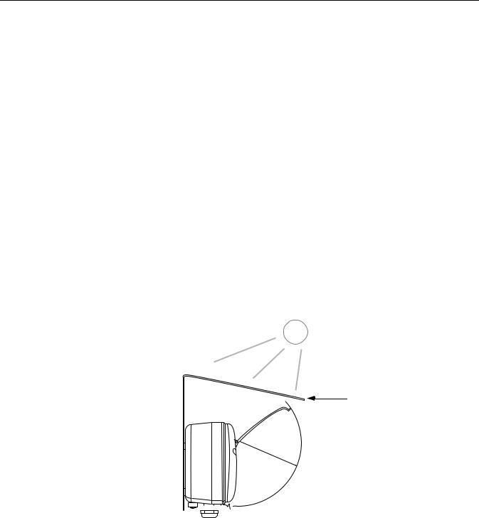
Figure 3-1. Space required for opening the lid
The Rosemount 2230 Graphical Field Display can be installed either on the tank roof or at the foot of the tank for a flexible and convenient read-out of tank data.
The 2230 is designed for mounting on a plate, on a wall, or on a pipe. The display is attached to the plate with four M4 screws. It is important to provide space for opening the weather protection lid which prevents degradation of the LCD display due to sunlight exposure.
Consider the following when finding an appropriate location for the Rosemount 2230 Graphical Field Display:
•Mount the 2230 in a location where it is protected from excessive sun light. This will reduce exposure to ultra violet (UV) radiation and extend the life-time of the LCD.
•In case the 2230 can not be protected from sun light and UV radiation, it is recommended that the weather protection lid (see “2230 Components” on page 2-2) is closed whenever the 2230 is not used.
•An optional weather protection is available as an alternative method to protect the 2230.
•When mounting the 2230 display ensure that sufficient space is provided for opening the lid, see Figure 3-1.
Weather protection (optional)
95 |
m |
|
|
|
|
|
|
|
m ( |
|
|
|
3. |
|
|
|
|
7 |
i |
|
|
|
n. |
|
|
|
) |
3-2 |
|
|
|
|
|
|
Section 3. Installation |
|
|
|
|
|
|
||
|
|
|
|
|
|
||
|
|
|
|
|
|
Reference Manual
300560EN, Rev AA
May 2011
Rosemount 2230
3.2.2Mounting the Graphical Display
The Rosemount 2230 Graphical Field Display is designed for mounting on a plate, wall, or pipe.
Mounting on a Plate
The 2230 display can be mounted on a plate by attaching four M4 screws to the back of the display. To mount the 2230:
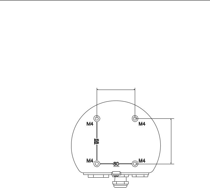
1.Drill four holes in the plate according to the hole pattern on the back of the 2230 display as illustrated in Figure 3-2.
2.Mount the 2230 on the plate using four M4 screws. Note that the M4 screws that are shipped with the 2230 display can be used as long as the plate thickness does not exceed 5 mm (0.2 in.).
Figure 3-2. Mounting hole
pattern
60 mm (2.4 in.)
68 mm (2.7 in.)
Section 3. Installation |
3-3 |
Reference Manual
Rosemount 2230
300560EN, Rev AA
May 2011
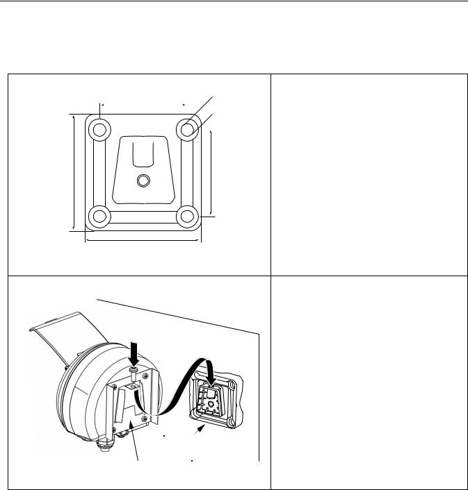
Wall Mounting with Bracket
The Rosemount 2230 Graphical Field Display can be mounted on a wall by using the optional mounting kit supplied by Rosemount Tank Gauging.
|
|
|
|
|
|
|
1. Mount the bracket on the wall by using |
|
70 mm |
four M8 screws and flat washers. |
|||||
|
|
|
|
|
Ø 9 mm |
Note! Countersunk screws are not |
|
|
|
|
|
||||
|
|
|
|
|
|
|
suitable. |
|
|
|
|
|
|
|
|
|
|
|
|
|
|
|
|
|
|
|
|
|
|
|
|
94 mm |
70 mm |
94 mm
2. |
Attach the mounting plate to the back of |
|
|
|
the 2230 housing. |
3. |
Attach the 2230 display to the bracket |
|
|
|
on the wall and tighten the locking |
|
|
screw. |
Screw |
||
Bracket
Mounting plate
3-4 |
Section 3. Installation |
Loading...