


GSP-2101 Artist
Studio Tube Preamp /
Multi-Effects Processor
Owner's Manual

C A U T I O N |
RIS K O F ELECTRI C SHOCK |
D O NO T OPEN |
ATTENTION: RISQU E D E CHO C ELECTRIQU E - N E PA S OUVRIR |
WARNING: T O REDUC E TH E RIS K O F FIR E O R ELECTRIC SHOC K D O NO T EXPOS E THI S EQUIPMEN T T O RAI N O R MOISTURE
The symbols shown above are internationally accepted symbols that warn of potential hazards with electrical products. The lightning flash with arrowpoint in an equilateral triangle means that there are dangerous voltages present within the unit. The exclamation point in an equilateral triangle indicates that it is necessary for the user to refer to the owner’s manual.
These symbols warn that there are no user serviceable parts inside the unit. Do not open the unit. Do not attempt to service the unit yourself. Refer all servicing to qualified personnel. Opening the chassis for any reason will void the manufacturer’s warranty. Do not get the unit wet. If liquid is spilled on the unit, shut it off immediately and take it to a dealer for service. Disconnect the unit during storms to prevent damage.
U.K. MAINS PLUG WARNING
A moulded mains plug that has been cut off from the cord is unsafe. Discard the mains plug at a suitable disposal facility. NEVER UNDER ANY CIRCUM-
STANCES SHOULD YOU INSERT A DAMAGED OR CUT MAINS PLUG INTO A 13 AMP POWER SOCKET. Do not use the mains plug without the fuse cover in place. Replacement fuse covers can be obtained from your local retailer.
Replacement fuses are 13 amps and MUST be ASTA approved to BS1362.
WARNING
FOR YOUR PROTECTION, PLEASE READ THE FOLLOWING:
WATER AND MOISTURE: Appliance should not be used near water (e.g. near a bathtub, washbowl, kitchen sink, laundry tub, in a wet basement, or near a swimming pool, etc). Care should be taken so that objects do not fall and liquids are not spilled into the enclosure through openings.
POWER SOURCES: The appliance should be connected to a power supply only of the type described in the operating instructions or as marked on the appliance.
GROUNDING OR POLARIZATION: Precautions should be taken so that the grounding or polarization means of an appliance is not defeated.
POWER CORD PROTECTION: Power supply cords should be routed so that they are not likely to be walked on or pinched by items placed upon or against them, paying particular attention to cords at plugs, convenience receptacles, and the point where they exit from the appliance.
SERVICING: To reduce the risk of fire or electric shock, the user should not attempt to service the appliance beyond that described in the operating instructions. All other servicing should be referred to qualified service personnel.
FOR UNITS EQUIPPED WITH EXTERNALLY ACCESSIBLE FUSE RECEPTACLE:
Replace fuse with same type and rating only.
ELECTROMAGNETIC COMPATIBILITY
This unit conforms to the Product Specifications noted on the Declaration of Conformity. Operation is subject to the following two conditions:
•this device may not cause harmful interference, and
•this device must accept any interference received, including interference that may cause undesired operation. Operation of this unit within significant electromagnetic fields should be avoided.
SAFETY INSTRUCTIONS
NOTICE FOR CUSTOMERS IF YOUR UNIT IS EQUIPPED WITH A POWER CORD.
WARNING: THIS APPLIANCE MUST BE EARTHED.
The cores in the mains lead are coloured in accordance with the following code:
GREEN and YELLOW - Earth BLUE - Neutral BROWN - Live
As colours of the cores in the mains lead of this appliance may not correspond with the coloured markings identifying the terminals in your plug, proceed as follows:
•The core which is coloured green and yellow must be connected to the terminal in the plug marked with the letter E, or with the earth symbol, or coloured green, or green and yellow.
•The core which is coloured blue must be connected to the terminal marked N or coloured black.
•The core which is coloured brown must be connected to the terminal marked L or coloured red.
This equipment may require the use of a different line cord, attachment plug, or both, depending on the available power source at installation. If the attachment plug needs to be changed, refer servicing to qualified service personnel who should refer to the table below. The green/yellow wire shall be connected directly to the unit's chassis.
CONDUCTOR |
WIRE COLOR |
|||
Normal |
Alt |
|||
|
|
|||
|
|
|
|
|
L |
LIVE |
BROWN |
BLACK |
|
|
|
|
|
|
N |
NEUTRAL |
BLUE |
WHITE |
|
|
|
|
|
|
E |
EARTH GND |
GREEN/YEL |
GREEN |
|
WARNING: If the ground is defeated, certain fault conditions in the unit or in the system to which it is connected can result in full line voltage between chassis and earth ground. Severe injury or death can then result if the chassis and earth ground are touched simultaneously.
LITHIUM BATTERY WARNING
CAUTION!
This product contains a lithium battery. There is danger of explosion if battery is incorrectly replaced. Replace only with an Eveready CR 2032 or equivalent. Make sure the battery is installed with the correct polarity. Discard used batteries according to manufacturer’s instructions.
ADVARSEL!
Lithiumbatteri - Eksplosjonsfare. Ved utskifting benyttes kun batteri som anbefalt av apparatfabrikanten. Brukt batteri returneres apparatleverandøren.
ADVARSEL!
Lithiumbatteri - Eksplosionsfare ved fejlagtig håndtering. Udskiftning må kun ske med batteri av samme fabrikat og type. Levér det brugte batteri tilbage til leverandøren.
VAROITUS!
Paristo voi räjähtää, jos se on virheellisesti asennettu. Vaihda paristo ainoastaan laitevalmistajan suosittelemaan tyyppin. Hävitä käytetty paristo valmistajan ohjeiden mukaisesti.
VARNING!
Explosionsfara vid felaktigt batteribyte. Använd samma batterityp eller en ekvivalent typ som rekommenderas av apparattillverkaren. Kassera använt batteri enligt fabrikantens instruktion.
18-0267-F

|
Table of Contents |
Section 1 - Introduction.................................................................................................................. |
4 |
Quick Start........................................................................................................................... |
4 |
About the GSP-2101 Artist ................................................................................................ |
5 |
Packaging ............................................................................................................................. |
5 |
Warranty.............................................................................................................................. |
6 |
Section 2 - The Basics |
|
Audio Connections ............................................................................................................. |
7 |
Guitar Inputs .......................................................................................................... |
7 |
2101 Outputs .......................................................................................................... |
7 |
1/4" vs. XLR Outputs.............................................................................................. |
7 |
FX Loop .................................................................................................................. |
7 |
Active Speaker Compensator ................................................................................ |
7 |
Phantom Power ...................................................................................................... |
7 |
Mono vs. Stereo Usage........................................................................................... |
8 |
Examples................................................................................................................. |
8 |
Power Connections.............................................................................................................. |
8 |
Applying Power ...................................................................................................... |
8 |
Power Cord ............................................................................................................. |
8 |
Power Switch.......................................................................................................... |
8 |
Other Connections.............................................................................................................. |
9 |
MIDI ....................................................................................................................... |
9 |
Control One Foot Controller................................................................................. |
9 |
Using Factory/User Programs ............................................................................................ |
10 |
Program Button/Data Wheel................................................................................ |
10 |
Bypassing the 2101 ............................................................................................... |
10 |
Copying Programs................................................................................................. |
10 |
Accessing the Tuner............................................................................................. |
10 |
Front & Rear Panel Diagrams............................................................................................ |
12 |
Section 3 - Editing Effects............................................................................................................. |
13 |
Programs vs. Algorithms.................................................................................................... |
13 |
FX Library Buttons............................................................................................................. |
14 |
Selecting and Modifying Parameters ................................................................................. |
14 |
Assigning Parameters to Function Keys ............................................................................ |
14 |
Comparing Programs ......................................................................................................... |
15 |
Naming Programs............................................................................................................... |
16 |
Storing Changes................................................................................................................. |
17 |
Analog Effects.................................................................................................................... |
18 |
Compression ......................................................................................................... |
18 |
Using the Distortions ........................................................................................... |
18 |
Tubes .................................................................................................................... |
18 |
Solid State ........................................................................................................... |
19 |
Analog 7-band GEQ ............................................................................................ |
19 |
Digital Noise Gate and Wet/Dry Mixer ............................................................................ |
20 |
Digital Effects..................................................................................................................... |
20 |
[EQ] FX Library .................................................................................................... |
20 |
[Reverb] FX Library .............................................................................................. |
22 |
Gated Reverbs ...................................................................................................... |
26 |
[Dly/Smp] FX Library............................................................................................ |
27 |
[Cho/Fla] FX Library............................................................................................. |
30 |
GSP-2101 Artist Owner’s Manual |
1 |

Table of Contents
Section 3 - Editing Effects (cont...).............................................................................................. |
32 |
[Pitch] FX Library ................................................................................................. |
32 |
[Gate] FX Library.................................................................................................. |
36 |
[More] FX Library ................................................................................................. |
38 |
[Mix] FX Library ................................................................................................... |
41 |
Why are there mixers?.......................................................................................... |
41 |
Optimizing Levels .............................................................................................................. |
43 |
Distortion On vs. Off Levels ................................................................................ |
44 |
Section 4 - Algorithm Usage......................................................................................................... |
45 |
Selecting Algorithms......................................................................................................... |
45 |
Using the [TEST] button................................................................................................... |
45 |
Constructing User Algorithms .......................................................................................... |
46 |
Maximum Algorithms .......................................................................................... |
46 |
Memory Usage Information ................................................................................. |
46 |
L/R DSP Inputs..................................................................................................... |
47 |
Algorithm Construction Hints ............................................................................ |
48 |
Entering/Exiting FX Edit Mode............................................................................ |
48 |
Adding FX Modules.............................................................................................. |
49 |
Deleting Individual FX Modules .......................................................................... |
51 |
Deleting All FX Modules ..................................................................................... |
52 |
Deleting Algorithms............................................................................................. |
52 |
Move Modules/Switch S-DISCs (PPC-210 Users Only)..................................... |
53 |
Step-by-Step (Simple Example)........................................................................... |
55 |
Linking (Audio Path Routing)............................................................................. |
55 |
Storing an Algorithm ........................................................................................... |
58 |
“Why can’t I copy over an existing Algorithm?” ................................................. |
59 |
Converting Algorithms from Single to Dual (PPC-210 Users Only) ................. |
60 |
Converting Algorithms from Dual to Single (PPC-210 Users Only) ................. |
61 |
Adding/Deleting Modules in Second S-DISC™ (PPC-210 Users Only) ........... |
61 |
Seamless Program Changes (PPC-210 Users Only) ............................................ |
62 |
Section 5 - The GSP-2101 and MIDI ......................................................................................... |
62 |
Main MIDI Receive Channel............................................................................................ |
62 |
Program Mapping............................................................................................................... |
63 |
Send Front Panel Program Change ................................................................................... |
63 |
Device Mapping................................................................................................................. |
64 |
Linking Parameters to MIDI Continuous Controllers ...................................................... |
65 |
Maximum Links per Program ............................................................................... |
65 |
Linked Parameter Example .................................................................................. |
65 |
Display Active Linked Parameter...................................................................................... |
67 |
About SysEx Dumps .......................................................................................................... |
67 |
System SysEx Data ............................................................................................... |
67 |
Program SysEx Data ............................................................................................. |
68 |
MIDI Merging.................................................................................................................... |
69 |
MIDI Program Load Type.................................................................................................. |
69 |
Section 6 - The GSP-2101 and the Control One Foot Remote................................................. |
70 |
Configuring the Pedalboard............................................................................................... |
70 |
Pedal Calibration.................................................................................................. |
70 |
Banks/Patches .................................................................................................................... |
72 |
2 |
GSP-2101 Artist Owner’s Manual |

|
Table of Contents |
Assigning Programs to Footswitches .................................................................... |
72 |
Assigning Parameters to Footswitches/Expression Pedals.................................... |
73 |
Other Footswitch Functions................................................................................. |
75 |
Program Up/Down................................................................................... |
75 |
Bank Up/Down........................................................................................ |
75 |
List Up/Down .......................................................................................... |
75 |
Toggle CCs .............................................................................................. |
75 |
Int. Pedal CC........................................................................................... |
75 |
Assigning MIDI to Expression Pedals .................................................................. |
76 |
Assign CC Number ................................................................................. |
76 |
CC Transmit Channel ............................................................................ |
77 |
Set MIDI CC Value Min/Max ................................................................ |
78 |
Other Pedalboard Tidbits .................................................................................................. |
80 |
Programming Set List ........................................................................................... |
80 |
LED Assignments ................................................................................................. |
81 |
Program/Bank/Tuner Switch................................................................................ |
81 |
Alternate Bank Up/Down Footswitches .............................................................. |
82 |
Section 7 - Other Utilities ............................................................................................................ |
83 |
Mono vs. Stereo Output Modes......................................................................................... |
83 |
Global EQ .......................................................................................................................... |
83 |
Factory Reset...................................................................................................................... |
84 |
Seamless Program Change Times...................................................................................... |
85 |
Section 8 - Advanced Applications .............................................................................................. |
88 |
Studio Hints....................................................................................................................... |
88 |
Using the 2101 for Studio Processing................................................................................ |
88 |
Alternate Set Up Configurations ...................................................................................... |
88 |
About SysEx Documentation............................................................................................ |
89 |
Section 9 - Appendix ..................................................................................................................... |
90 |
Special Characters ............................................................................................................. |
90 |
Harmony Interval Charts .................................................................................................. |
90 |
Memory Usage Chart......................................................................................................... |
91 |
Factory Algorithm Diagrams ............................................................................................. |
93 |
PPC-210 Algorithm Diagrams ........................................................................... |
100 |
Factory Program List........................................................................................................ |
101 |
PPC-210 Program List ........................................................................................ |
102 |
Audio Block Diagram ...................................................................................................... |
103 |
MIDI Implementation Chart........................................................................................... |
104 |
Specifications................................................................................................................... |
105 |
Index................................................................................................................................. |
106 |
GSP-2101 Artist Owner’s Manual |
3 |

Introduction
Section 1 - Introduction
QUICK START
For those of you who prefer to burn now and read later, we've included this Quick Start section to help you do it right the first time.
Connect Cables: Connect audio input and output cables to the rear jacks. Balanced (tip-ring- sleeve), unbalanced (tip-sleeve) or balanced XLR cables can be used with the output jacks. The rear headphone jack permits you to use the GSP-2101 Artist without an amplifier.
Apply Power: Use the supplied AC power cord to connect the GSP-2101 Artist to an appropriately grounded outlet. Be sure you run all your power cables away from audio cables. This will prevent noise and stray magnetic fields from entering the signal path.
Effects Loop: Connect any external effects devices to the GSP-2101 Artist effects send and return jacks. NOTE: External devices should return the same signal level to the GSP-2101 Artist as they receive from the GSP-2101 Artist. This will avoid level changes when switching the effects loop in and out. This signal level relationship is called unity gain.
Connect Control One Foot Controller (if applicable): Connect the output of the optional DigiTech Control One foot controller to the Foot Controller jack found on the rear of the GSP2101 Artist. DO NOT CONNECT ANYTHING BUT THE OPTIONAL DIGITECH CONTROL ONE FOOT CONTROLLER TO THE FOOT CONTROLLER JACK ON THE REAR PANEL! DOING SO MAY DAMAGE THE DEVICE. IF YOU WANT TO USE MIDI CONTROL, CONNECT THE DEVICE(S) TO THE MIDI IN JACK.
Adjust Input: Set the instrument to the loudest operating level that will be used. Make sure your amp is set for a clean sound, that your tone controls are all neutral (flat), and the amplifier's main volume is all the way down.
Adjust Output: Set the GSP-2101 Artist output level to the 12 o'clock position, and turn up the amplifier's main volume to the desired level.
Select Program: Begin playing your guitar, and choose any program using the Data wheel, or the Program Up/ Down buttons. Programs 1-100 are user-programmable, and you can modify and store them as you want. Programs 101-240 are duplicates of the first 100. Programs 101-240 cannot be overwritten.
4 |
GSP-2101 Artist Owner’s Manual |

Section 1 - Introduction
ABOUT THE GSP-2101 ARTIST
Congratulations, and thank you for your purchase of the DigiTech GSP-2101 Artist Studio Tube Preamp/Multi-Effects Processor. The original GSP 2101 has become the world's most popular professional guitar processor and to prove it, many of the industry's top players have contributed their own presets to the GSP-2101 Artist. The GSP-2101 Artist continues to go beyond the expected, offering total flexibility and control of the best digital effects in the industry. Special features include:
•Full bandwidth effects (20-20kHz)
•24-bit signal path, 48-bit internal data path
•Any digital effect can appear at any point in any effects chain
•Number of simultaneous effects limited only by available CPU and RAM blocks in the unit
•Programmable Algorithms allow you to create an unlimited variety of custom effects configurations
•Effects can be repeated in a chain, e.g. EQ + flange + EQ + pitch shift + pitch shift
•Instant Module and Parameter access
•Multiple dynamic effects capability (e.g. chorus + flange+ pitch shift)
•Expandable to 2x factory memory and processing with optional PPC-210
•Balanced, speaker-compensated outputs for running direct to a mixing console
•World-class tube preamp with six distortion types (3 tube, 3 solid state)
•DigiTech’s exclusive modulation delays
•New and improved chromatic tuner
•New Effects include: improved Whammy™, Chromatic Pitch Shifter, New Harmony Intelligent Pitch Shifting, and Programmable Cabinet Emulation
•Built-in tone generator
•Digital and analog EQ
•MIDI input filtering and MIDI Merging
•MIDI program transmit and receive mapping
•All Effects and Parameters available for MIDI continuous control
•Optional Control One foot controller with built-in Expression Pedal for ultimate programmability and control
This owner's manual is your key to understanding the powerful world of the GSP-2101 Artist. Read it carefully. After you've had time to familiarize yourself with the unit, try experimenting with unusual effects combinations or routings. You may get some interesting results. Good luck, and thank you for choosing DigiTech.
PACKAGING
The GSP-2101 Artist’s shipping box contains:
-This Owner's Manual
-The GSP-2101 Artist
-An AC power cord appropriate for the country in which you bought this product
-Four screws for mounting the GSP-2101 Artist in a rack.
Introduction
GSP-2101 Artist Owner’s Manual |
5 |

Section 1 - Introduction
WARRANTY
Introduction |
2. DigiTech warrants this product, when used solely within the U.S., to be free from defects in |
|
|
1. |
The warranty registration card must be mailed within ten days after purchase date to validate |
|
|
this warranty. |
|
|
materials and workmanship under normal use and service. |
|
3. |
DigiTech liability under this warranty is limited to repairing or replacing defective materials |
|
|
that show evidence of defect, provided the product is returned to DigiTech WITH RETURN |
|
|
AUTHORIZATION, where all parts and labor will be covered up to a period of one year. A |
|
|
Return Authorization number may be obtained from DigiTech by telephone. The company |
|
|
shall not be liable for any consequential damage as a result of the product's use in any circuit |
|
|
or assembly. |
|
4. |
Proof-of-purchase is considered to be the burden of the consumer. |
|
5. |
DigiTech reserves the right to make changes in design, or make additions to, or improvements |
|
|
upon this product without incurring any obligation to install the same on products previously |
|
|
manufactured. |
|
6. |
The consumer forfeits the benefits of this warranty if the product's main assembly is opened |
|
|
and tampered with by anyone other than certified Digitech technician or, if the product is |
|
|
used with AC voltages outside of the range suggested by the manufacturer. |
|
7. |
The foregoing is in lieu of all other warranties, expressed or implied, and DigiTech neither |
|
|
assumes nor authorizes any person to assume any obligation or liability in connection with the |
|
|
sale of this product. In no event shall DigiTech or its dealers be liable for special or conse- |
quential damages or from any delay in the performance of this warranty due to causes beyond their control.
DigiTech™, S-DISC™, Whammy™, AutoLink™, and Silencer™ are registered trademarks of DOD Electronics Corporation.
NOTE: The information contained in this manual is subject to change at any time without notification. Some information contained in this manual may also be inaccurate due to undocumented changes in the product or operating system since this version of the manual was completed. The information contained in this version of the owner's manual supersedes all previous versions.
6 |
GSP-2101 Artist Owner’s Manual |

Section 2 - The Basics
AUDIO CONNECTIONS
Guitar Inputs - The GSP-2101 Artist provides two jacks to choose from when connecting your guitar. One on the front, and one one the back (see diagrams 2-4 & 2-5 ). They are identical except that the front input jack takes priority over the rear input jack (i.e. when you use the front jack, the rear jack becomes inactive). The rear jack is provided for those who "hard-wire" their equipment into racks and prefer to run their cables behind the equipment instead of the across the front.
2101 Outputs - The GSP-2101 Artist includes both balanced 1/4" and XLR outputs (see diagram 2-5). The 1/4" outputs are commonly used to feed a guitar amp(s), and the XLRs are usally connected to a mixing console (in both live and recording studio situations). Be sure to keep levels low to avoid possible speaker damage when making these audio connections.
1/4" vs. XLR Outputs - These outputs are identical except, the Active Speaker Compensator circuit only effects the XLR outputs. This allows a player to run an amp set-up on stage, while simultaneously sending signal to a mixing console using the Active Speaker Compensator.
FX Loop - The GSP-2101 Artist provides a programmable line level mono send/stereo return FX loop (see diagram 2-5). This allows you to insert additional processing into the 2101's signal path. The signal leaves the box after the Preamp and EQ circuits, and returns just before the A/D convertors for the digital processing (see Block Diagram ). Although the A/D converters usually only receive a mono signal from the analog section, the FX Loop Returns can be used for either mono (left jack only) or stereo applications (both jacks).
How the FX Loop Return’s signals combine with the original signal can be defined and stored into each Program, using the following settings:
Bypass - The FX Loop Returns are off, and completely ignored.
Summed - The FX Loop Returns are summed together with the original signal using a 50:50 ratio.
No Sum - If plugs are connected to the FX Loop Return jack(s), they are the primary signal source. If there is no signal present at these jacks, you don't hear anything from the GSP-2101 Artist. When the jacks aren't used, No Sum behaves the same as the FX Loop Bypass setting.
Every Program in the 2101 has the FX Loop set to bypass, so you will need to turn the loop on in each Program that requires the external processing. See Editing Effects on pg. 13 for information concerning parameter editing.
Active Speaker Compensator- The GSP-2101 Artist includes special circuitry before the XLR and Headphone outputs that simulates the sound of microphoned guitar cabinets. The Active Speaker Compensator is engaged when the button next to the XLR out jacks is pressed in. This circuit is extremely useful for recording studio applications, or connecting the 2101 directly to the mixing console in live applications. Guitar speakers are not flat, full frequency transducers. The Active Speaker Compensator simulates the frequency response and behavior of a common 4 x 12 Cabinet, giving you true guitar speaker sound without extra baggage!
Phantom Power - The GSP-2101 Artist has no need for Phantom Power supplied by mixing consoles. If your console doesn't allow you turn off Phantom Power to individual channels, don't worry, the 2101 will survive. However, with all equipment exposed to Phantom Power, you should always engage the Phantom Power AFTER all audio connections are completed.
The Basics
GSP-2101 Artist Owner’s Manual |
7 |

Section 2 - The Basics
Mono vs. Stereo Usage - The GSP-2101 Artist can be used in either mono or stereo output applications. When using the 2101 in a mono application, you should set the Output Mode to Mono (found in the Utilities menu). This will ensure that you hear both sides of multi-tap delays, etc. (Please see page 83 for more information regarding Mono/Stereo usage).
Examples - Figures 2-1 and 2-2 show common ways to connect your GSP-2101 Artist to guitar amps and speakers. Once you have everything plugged in, set the amps to clean settings. Remember, the better your rig sounds when clean, the better your 2101 will perform.
Basics The
Fig 2-1
Fig 2-2
POWER CONNECTIONS
Applying Power - The GSP-2101 Artist, like any piece of computer hardware, is sensitive to voltage drops, spikes, and surges. Interference such as lightning or power "brownouts" can seriously, and in extreme cases, permanently damage the circuitry inside the unit. Always be sure to connect your 2101 to well grounded AC outlets. You may wish to implement a Spike/Surge Suppressor or AC Line Conditioners to further protect your investment.
Power Cord - Use the power cord supplied with the GSP-2101 Artist when making your AC connections. The power cord should be appropriate for the country where the 2101 was sold. If not, please contact your DigiTech dealer immediately. This cord connects to the back of the 2101 using the AC Line Input Jack (see fig 2-5 on pg. 12).
Power Switch - Lets you to turn On/Off the GSP-2101 Artist (see fig 2-4 on pg. 12).
8 |
GSP-2101 Artist Owner’s Manual |
Section 2 - The Basics
OTHER CONNECTIONS
MIDI - The GSP-2101 Artist is MIDI savvy. Much of the 2101's flexibility can be accessed remotely using MIDI, allowing you to focus more on your playing. The 2101 is complete with the standard MIDI In, Out and Thru jacks on the rear of the unit (see figure 2-5). Connect a MIDI controller (such as a MIDI sequencer, or perhaps a DigiTech MC2 continuous controller pedal) to the MIDI In jack for remote or automated control of the 2101. MIDI System Exclusive Data, Program Changes, and Continuous Control information can be sent from the 2101 using the MIDI Out jack. The MIDI Thru jack is used to pass along MIDI information received at the MIDI In jack. MIDI information created by the 2101 can be Merged with incoming data and passed to the MIDI Out jack, offering a second Thru option for your MIDI applications. Please see section 5 for more information concerning the 2101 and MIDI (pg. 63).
Control One Foot Controller - DigiTech offers an optional pedalboard designed to get the most out of your GSP-2101 Artist, called the Control One foot controller (see fig 2-3). The Control One features 10 footswitches that can be programmed to select a new program, change banks, or change parameter values. It also includes a built-in Expression Pedal for changing parameters in real-time. The Control One is connected to the Foot Controller Input on the rear of the unit (see figure 2-5).
WARNING: This jack supplies voltage to the Control One. Do not plug any device other than the Control One into the Foot Controller Input jack.
The cable that connects the 2101 to the Control One uses 5-pin DIN connectors commonly used by MIDI devices. Should the cable ever need replacing, a standard MIDI cable will do the job, as long as all 5 pins are wired (MIDI only requires 3 active pins, but most MIDI cables wire all 5).
Fig 2-3
The Basics
GSP-2101 Artist Owner’s Manual |
9 |

Basics The
Section 2 - The Basics
USING FACTORY/USER PROGRAMS
The GSP-2101 Artist contains 100 User Programs and 140 Factory Programs. The Factory Programs cannot be copied over, while the User Programs can be copied over. Many of the Factory Programs have been placed in User Program positions for your convenience.
Program Buttons/Data Wheel: The Program [Up/Down] buttons (see fig 2-4) let you select any Program in the 2101 Artist. The Program Up button selects the next Program, while Program Down selects the previous Program.
The Data Wheel can also be used to select Programs, but only when the Program's Title Screen is being displayed. The Data Wheel is very convenient for scrolling quickly from one Program to another.
Bypassing the 2101: All of the 2101’s effects can be Bypassed at one time by pressing the [BYPASS] button on the front panel. Press [BYPASS] again to exit Bypass mode. Bypass mode can also be accessed using the Control One foot controller.
Bypass LED indicator - This LED is located in the Display Window (see pg. 12) and indicates (when lit) that all effects have been bypassed using either the Bypass button or the optional Control One foot controller.
Copying Programs: Any of the GSP-2101 Artist's 240 Programs can be copied to a User Program location. To copy a Program, do the following:
• Press the [STORE] button, the display reads:
Copy
Dry Saturated Tube
To: 1
Dry Saturated Tube
•Select the User Program position where you want to place a copy of the selected Program (using the Data wheel or Program [UP] / [DOWN] keys), and press [STORE] again. The display briefly reads:
***Copying ***
after which, you will automatically be returned to Program's Title Screen. To abort the copy command, press [COMPARE].
If a new Program is stored in a location where a Program already exists, the old Program will be overwritten by the new one. Make sure you know where you’re storing your Programs to avoid accidental loss of valuable sounds.
10 |
GSP-2101 Artist Owner’s Manual |

Section 2 - The Basics
Accessing the Tuner/Tone Generator: The GSP-2101 Artist comes complete with a full-function chromatic tuner and tone generator. To access the tuner, press the [TUNER] button. The display reads:
Tuner A = 440
---- -- -- -- -- --
---- -- -- -- -- --
As you play a note on the guitar, line two of the display will tell you which note you are playing. The 3rd and 4th lines of the display will begin to show characters moving to the left or to the right. If the characters are moving right, the note you are playing is sharp. If the characters move left, you are flat. The goal is to tune your guitar so that the characters stop moving, and the display indicates you are in tune.
The tuner is referenced to A=440Hz. If you prefer tuning sharp or flat according to the A reference, use the Data Wheel to select a new reference. This can be set as high as A=453Hz or as low as A=427Hz. The tuner can also be used for alternate tuning references where A=Ab (meaning you play an A chord, but you hear an Ab chord). It is possible to tune as low as A=Gb.
Press the [Tuner] button to exit the Tuner.
To access the Tone Generator, press and hold the [Tuner] button. The display reads:
Tone Generator
Lev 0
E2: 82.41 Hz
Press the [1] button, then use the Data wheel to modify the Level parameter. Pressing button [2] and then using the Data Wheel lets you select the tone that is being generated. The tone generator can be very helpful in helping other musicians tune their instruments to your reference.
Press the [Tuner] button to exit the Tone Generator.
The Basics
GSP-2101 Artist Owner’s Manual |
11 |

Section 2 - The Basics
FRONT & REAR PANEL DIAGRAMS
Basics The
Fig 2-4
Fig 2-5
12 |
GSP-2101 Artist Owner’s Manual |

Section 3 - Editing Effects
PROGRAMS VS. ALGORITHMS
For a Program to function, it must have an Algorithm assignment. In simplest terms, an Algorithm is a group of effects connected together in a specific way. Algorithms tell the GSP2101 Artist which effects to use, while Programs tell the Algorithm how the effects should sound (by setting the parameters to the stored values).
An Algorithm contains a group of single-pur- pose effects called FX Modules (see fig. 3-2). Each FX Module contains its own set of Parameters, and is designed to perform a specific function. It is within these individual Modules, and their ability to be used in groups or to stand alone that, the full power of the GSP-2101 Artist is utilized. When combined in groups, virtually any imaginable effects combination and routing is possible.
Figure. 2-3 shows an example of two different Algorithms assigned to three Programs. Notice that Algorithm A is assigned to both Programs 1 and 3, while Algorithm B is assigned to Program 2 only. (Using a single Algorithm for more than one Program is common. Because,
Programs with the same effects Modules and routings as other Programs are often needed, but with slightly different Parameter settings for each effect.).
Since Algorithms can be modified, there are some rules concerning when User Algorithms can be changed, and when they can not. For more information, refer to Section 4 Algorithm Usage on pg. 45.
Essentially, every Program's first Parameter is the Algorithm select screen. When the 2101 displays the Program's title screen,the Algorithm select screen is reached by pressing the Parameter [NEXT] button once. All the FX Modules and their Parameters are found immediately after the Algorithm select screen. Fig 3- 2 shows how a Program's Parameter Pages arelinked in a circular fashion.
Editing Effects
Fig 3-3
GSP-2101 Artist Owner’s Manual |
13 |

Effects Editing
Section 3 - Editing Effects
FX LIBRARY BUTTONS
The FX Library buttons (see fig 2-4 on pg. 12) make the GSP-2101 Artist easier and faster to use. These buttons let you jump to the first Parameter page of each Module used in the Program. From there, you can scroll to the Parameter you want using the Parameter [NEXT] and [PREV] buttons. For example: if a Program uses an algorithm that contains two choruses and one reverb effect, you can jump directly to the first chorus module by pressing the [CHO/FLA] button, and get to the second chorus module by pressing the [CHO/FLA] button again. The [NEXT] button could have taken you to the same location, but the FX Library Buttons made things much quicker.
There are two buttons found in this button array that aren't labeled with names. They are the [<] and [>] buttons. These two buttons allow you to jump from effect module to effect module. This is helpful when you're not sure of the effect order, and you don't wishto scroll through all the parameters. Press the [>] button to access the next effect module in the algorithm, or the [<] button to jump to the previous module.
SELECTING AND MODIFYING PARAMETERS
Using the Program's Title Screen as a starting point, press one of the FX Library buttons, or [Prev] or [Next] buttons to enter Edit Mode. Once in Edit Mode, you will see that Parameters are often logically grouped into sets of two and three like this:
Stereo Noise Gate
SNGt |
|Thresh|Hyster |
On |
|-64dB |6dB |
To select one of the three displayed parameters, press either the [1], [2], or [3] button. Once you have selected the Parameter, use the Data Wheel to adjust the value. Pressing the [1], [2], or [3] button again will cause the value to increment or decrement (depending on its current assignment and the last direction it was moved). To retain any changes you have made to a Program, Store it before changing Programs (see Storing Changes pg. 17)
ASSIGNING PARAMETERS TO FUNCTION KEYS
The Function keys ([1], [2], and [3]) are user-programmable buttons that let you access and tweak up to three of your most commonly used Parameters in a Program, from the Program Title Screen.
If you find that you need to adjust delay times frequently, you could set up a Function key to give you instant access to the delay time Parameter, enabling you to tweak it’s value quickly and easily. This feature is great for maximizing productivity in the studio, or fixing something fast in a live performance situation.
14 |
GSP-2101 Artist Owner’s Manual |

Section 3 - Editing Effects
Suppose you’re using a stereo chorus and that you want to assign Function key [1] to the chorus speed Parameter. The procedure is as follows:
•Using the Parameter [NEXT] / [PREV] keys, scroll to CHORUS SPEED.
•Press and hold Function key [1] for about two seconds. After a short pause, The dis-
play reads:
Select parameter's
location |
on program |
|
screen |
|
|
¨ |
¨ |
¨ |
•Select the Program screen location where you want the Parameter to appear by pressing Function key [1], [2], or [3].
After you’ve selected a location in the Program screen for the Parameter, the GSP-2101 Artist returns to the place in the Parameter menu where you left off.
If you decide you want to change the Function key assignment for that Parameter, repeat the process, and select a different location. If you want to leave a Parameter with no Function key assignment, press its assigned Function key again, and the Function key will be disconnected from the Parameter. After you've made your Function key assignments, you’ll need to store the Program in order to retain the changes. See pg. 17 for information on Storing Programs.
The special characters used to indicate Function key assignments are as follows:
¡ Indicates that Access key [1] has been assigned to the Parameter shown in the display. ™ Indicates that Access key [2] has been assigned to the Parameter shown in the display. £ Indicates that Access key [3] has been assigned to the Parameter shown in the display.
COMPARING PROGRAMS
The [COMPARE] button lets you compare a modified Program to the original program without losing the modifications you have made. This feature makes the difference between Programs clear, and provides an easy reference point for creating new Programs.
To compare a modified Program to the original:
•Press the [COMPARE] button. The GSP-2101 Artist will temporarily switch to the original Program settings, and the display will read:
*** |
*** |
***COMPARING ***
*** |
*** |
Now you can hear what the original Program sounds like. Press the [COMPARE] button again to switch back to the edited version.
The GSP-2101 Artist will not respond to any buttons or commands while in Compare mode.
Editing Effects
GSP-2101 Artist Owner’s Manual |
15 |

Effects Editing
Section 3 - Editing Effects
NAMING PROGRAMS
The GSP-2101 Artist lets you give your Programs and Algorithms custom names (up to 20 characters in length). Use the Data wheel and the Function keys to make naming quick and easy. Function key [1] changes the character from upper to lower case and vice versa. Function key [2] inserts a space into the Program name, and Function key [3] jumps to the numbers in the character set.
To custom name a Program or Algorithm, do the following:
• Press the [NAME] button once. The display looks something like this:
Dry Saturated Tube
¡CAPS ™SPC £NUM
The numbers preceding each option indicates the Function key that will perform the function shown.
•Using the Data wheel, scroll to the character you want to use, or press one of the Function keys. When you have selected the character you want, press the Parameter [NEXT] button. Note that the cursor moves to the next character. Repeat this procedure until the display shows what you want.
Unique to the GSP-2101 Artist are several special naming functions. The [<], and [>] buttons in the FX Library group let you bump an entire name, or section of a name, left or right in onespace increments. Whether you move left or right, all characters to the right of the cursor will move.
The Program [UP] button copies a character into memory. This lets you place a copy of that character (using the Program [DOWN] key) anywhere in the name.
NOTE: if you exit the name mode before storing, an asterisk appears in the upper right corner of the display. This means that you must store the changes you have made in order for your custom Program name to be retained in memory.
16 |
GSP-2101 Artist Owner’s Manual |

Section 3 - Editing Effects
STORING CHANGES
For modified Programs to be available for later recall, you must store them in memory. To store a Program, do the following:
•After you have changed the Program, press the [STORE] button once. The display looks something like this:
Save
Dry Saturated Tube
To: 1
Dry Saturated Tube
This screen lets you choose where you want to store the new Program.
•Using the Program buttons or the Data wheel, scroll to the Program number you want to store the new Program to.
•To store the Program, press the [STORE] button again. The display briefly reads:
***Storing ***
after storing you will automatically be returned to the current Program. To abort the [STORE] command, press [COMPARE].
Editing Effects
GSP-2101 Artist Owner’s Manual |
17 |

Effects Editing
Section 3 - Editing Effects
ANALOG EFFECTS
Every Program has a set of analog effects whose signal routing order is always fixed. These analog effects include Compression, Distortion, and a 7-band Graphic Equalizer.
Compression: Every Program in the GSP-2101 Artist has a dynamic range compression circuit specially designed for use with guitars. Compression does exactly what its name implies; it compresses the dynamic range of a signal. It does this by turning signals down as they become louder. After it makes the adjustment to the level, it boosts the overall signal back up. This can be used to increase sustain, and tighten up guitar signal, and is particularly useful on clean sounds. Parameters of the GSP-2101 Artist compressor are as follows:
Effect On / Off: Turns the Module on or off. When Modules are turned off, their Parameters are not displayed. To see the Parameters, you must turn the Module on.
Compression Ratio: Controls the amount of gain reduction for a given input signal level. This means that if RATIO is set to 2:1, every 2 dB increase in input level results in a 1 dB increase in compressor output. Likewise, if RATIO is set to 5:1, every 5 dB increase in input level will result in a 1 dB output level increase. The higher the RATIO setting, the more compressed the output signal becomes. Ranges from 1.5:1 to infinity:1.
Threshold: Sets the minimum input level at which the compressor will engage. As THRESHOLD is lowered, the compressor engages at lower input levels, causing the apparent output level to decrease. Ranges in 5 dB steps from -30dB to -45 dB.
Output Level: Adjusts the overall output level of the compressor. Ranges in 6 dB steps from -6 dB to +6 dB.
Distortions: The distortion section of the GSP-2101 Artist is capable of producing six distinctly different types of distortion: three are tube-driven (using 12AX7’s), and three are solid state. Any one of these distortions is available in every 2101 Program.
Tube Distortions: We’ve provided you with two completly separate gain controls in the tube section.
The first gain control adjusts how hard the guitar signal hits the first 12AX7 tube. This control is very useful in compensating for different pickup strengths from your guitar. If one of your guitars provides a very strong signal, you will hear more distortion than guitars with weaker pickups. Use the first gain control to help match the distortion sound between the two guitars.
The second gain control adjusts how much gain is applied to the signal feeding the second 12-AX7 tube (the signal being the result of the first 12AX7 tube). This is where distortion really starts to build. Thousands of tonal possibilities are available by using different combinations of Gain1 and Gain2. Low Gain1 and High Gain2 settings produce more dynamic type distortions while, the opposite provide more tones with more natural edge. Using high settings for Gain1 and Gain2, offer more than enough distortion for most applications.
The 2101 gives you three types of tube circuitry to choose from. Saturated tube offers tight, all out gain possibilities. Distorted tube has less gain overall, and is a little looser in the bottom end. It also has a little darker natural tone overall.
18 |
GSP-2101 Artist Owner’s Manual |
Section 3 - Editing Effects
While turning the distortion OFF gives you a clean sound, many guitarists prefer the sound of the tube when it is not overdriven. We call this the Clean Tube setting. It uses the first 12AX7 tube and has one gain control. This clean setting can still be used for very subtle distortion when Gain1 is set very high.
Solid State Distortions: The GSP-2101 Artist has three solid-state distortions. These three distortions are: OVERDRIVE - A gentle overdrive with extra punch for bluesier tones. HEAVY SUSTAIN - Smooth, warm distortion sound with a lot of sustain. Great for really smooth lead tones. GRUNGE - This has tons of gain with loads of bottom end, while still remaining tight and highly focused.
Distortion Parameters are as follows:
Effect On / Off: Turns the Module on or off. When Modules are turned off, their Parameters are not displayed. To see the Parameters, you must turn the Module on.
Distortion Type: Selects the type of distortion to be used in the Program. They are: SATURATED TUBE , DISTORTED TUBE , CLEAN TUBE , HEAVY SUSTAIN, and GRUNGE
Distortion Gain(#): Controls the gain stage(s) of the distortion. Solid state distortions have one gain stage, and tube distortions (except CLEAN TUBE) have two. In tube distortions, GAIN1 and GAIN2 act independently to produce different tonal characteristics at different setting combinations.
Analog 7-band GEQ: Included in every 2101 Program, is a seven-band analog graphic equalizer with ±12 dB cut or boost in 2 dB steps. Frequency centers are: 80, 160, 320, 640, 1.28k, 2.56k, and 5.12k Hz. Use the [NEXT] and [PREV] keys to select the frequency you want to modify. Use the Data wheel to boost or cut the selected frequency.
Editing Effects
GSP-2101 Artist Owner’s Manual |
19 |

Effects Editing
Section 3 - Editing Effects
DIGITAL NOISE GATE AND WET/DRY MIXER
There are two digital effect modules present in every GSP-2101 Artist Program: The digital noise gate and the wet/dry mixer. The digital noise gate uses DigiTech’s Silencer™ technology, and is used for eliminating excess noise or creating special effects. This module appears in the FX Library when creating your own Algorithms. There may be some unique applications where you want to place a noise gate somewhere else in the effect chain. For more information on noise gate Parameters, see pg. 36.
The wet/dry mixer control is used to quickly change the overall effects level of a Program. If a Program has too much effect for your taste, press the [MIX] button, and the 2101 will jump to the wet/dry Parameter screen. Use the Data Wheel to adjust this relationship. Remember to store the Program after you change it (see pg. 17).
DIGITAL EFFECTS
All digital Modules can be placed anywhere in a signal path, and routed any way you choose. This flexibility puts S-DISC processing in a class of its own.
[EQ] FX Library
Module Name |
Module Abbrv. |
Description |
6Bnd GEQ |
GEQ6 |
Full bandwidth 6-band graphic equalizer |
|
|
|
10Bnd GEQ |
GEQ10 |
Full bandwidth 10-band graphic equalizer |
|
|
|
15 Band GEQ |
GEQ15 |
Full bandwidth 15-band graphic equalizer |
|
|
|
Low Pass Filter |
LPF |
Double-pole low-pass filter |
|
|
|
High Pass Filter |
HPF |
Double-pole high-pass filter |
|
|
|
1Bnd ParamtrcEQ |
PEQ1 |
1-band parametric equalizer |
|
|
|
3Bnd ParamtrcEQ |
PEQ3 |
3-band parametric equalizer |
|
|
|
5Bnd ParamtrcEQ |
PEQ5 |
5-band parametric equalizer with shelving high and low |
|
|
|
Band Pass Filter |
BPF |
Double-pole bandpass filter |
|
|
|
Notch Filter |
Notch |
Double-pole notching (cut only) filter |
|
|
|
Cabinet Emulator |
Cab |
Guitar Cabinet/Speaker Emulation |
|
|
|
The equalizer Modules provided in the GSP-2101 Artist offer superb noise performance and allow accurate tonal shaping of many different types of sound sources. There are three different graphic EQs: the high-pass, low-pass, bandpass, and notch filters. All allow precise band limiting of source material. Parametric equalizers are represented in 1-band, 3-band, and 5-band Modules, all with adjustable Qs (see discussion of Q on next page). The 5-band parametric has shelvingtype, high and low-frequency controls, each with selectable frequencies.
A Programmable cabinet emulator can be used in place of the analog cabinet emulation provided at the XLR outputs. This lets you decide Program by Program whether or not to use cabinet emulation.
20 |
GSP-2101 Artist Owner’s Manual |
Section 3 - Editing Effects
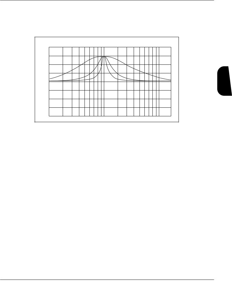
Adjustable Q equalizers offer the ability to control the bandwidth of the boost/cut ranges. High Q settings (Q=8) yield extremely narrow bandwidths, where boost and cut have minimal effect on frequencies adjacent to the center frequency. Fig. 3-4 shows how low Q settings affect a wider number of frequencies when the selected band is boost or cut.
DigiTech Audio Precision STD AMPL (dBr) vs FREQ (Hz)
20.000
15.000
10.000
5.0000
0.0
-5.000
-10.00
-15.00
-20.00
100
2 |
|
= |
4 |
Q |
|
|
= |
|
Q |
8 = Q
1k |
10k |
Fig 3-4
With a Q setting of 2, you can see that a large number of frequencies are affected by boosting the center frequency. Look at the middle and lower curves in the diagram. The curves with Q setting of 4 and 8 have a much narrower bandwidth.
The cabinet emulator’s parameters are as follows:
Effect On / Off: Turns the Module on or off. When the cabinet emulation Module is turned off, the sound continues to pass through the Module.
Type: There are 10 cabinet types that can be selected. They range from 1-Warm to 10MaxBndwidth. The maximum bandwidth setting is the same as having the cabinet emulator module bypassed.
Editing Effects
GSP-2101 Artist Owner’s Manual |
21 |

Effects Editing
Section 3 - Editing Effects
[Reverb] FX Library
Module Name |
Module Abbrv. |
Description |
Multi-FX Reverb |
MVerb |
For use in multi-effects Algorithms |
|
|
|
BigVerb |
Big |
High-quality reverb |
|
|
|
GigaVerb |
Gig |
Professional studio reverb |
|
|
|
Gated Reverb |
GtRvb |
Mono in, stereo out gated reverb |
|
|
|
Stereo Big Reverb |
SBig |
True stereo high-quality reverb |
|
|
|
Stereo Gigaverb |
SGig |
True stereo professional studio reverb |
|
|
|
Stereo Gated Reverb |
SGtRv |
Stereo in /out gated reverb |
GigaVerb has 20 Parameters, that give exceptional soundfield and tonal shaping control over reverberation. It is best suited for simulating natural room environments that have no acoustic treatment, like churches and assembly halls. A one input/four output GigaVerb Module, is capable of producing reverberation of virtually any size, shape, depth, timbre or soundfield location.
Bigverb is a slightly trimmed version of the GigaVerb, offering much of the same flexibility and controls as GigaVerb, but using less memory. Bigverb lets you produce a high-quality reverb, while including one or two other small Modules in the Algorithm.
Like Bigverb, MFX Reverb is a slimmer and trimmer version of GigaVerb, but MFX Reverb is specifically designed to fit efficiently into Algorithms, using multiple effects Modules.
Also available, are true stereo reverbs: Stereo GigaVerb and Stereo Bigverb. These Modules allow channel inputs to remain totally discrete, thereby retaining the imaging of stereo input sources. These reverbs also offer stereo mix controls that allow mixing of leftand right-channel early reflections and reverberations. These controls can be used to blur stereo imaging of input sources, creating a subtle stereo ambience rather than fully discrete reverberation channels.
Before covering all the reverb Parameters and their definitions in detail, let’s discuss the benefits and theory behind reverberation.
Reverberation, or room ambience, occurs when acoustic energy is reflected off room surfaces, materials, and objects. Using reverberation with your guitar gives the listener a sense that the material is being performed in an environment where you are not actually present.
The GSP-2101 Artist uses early reflections in several Modules to get a better emulation of the natural sound of a room. Early reflections are short clusters of direct reflections from the room’s closest walls. In an average size room, these direct reflections usually occur within the first 30 to 100 milliseconds, depending on the size of the room and the placement of the sound source within the room. Adding these early reflections to the reverberation increases the perceived reverberation time and the apparent size of the reverberant space. Adding more than small amounts tends to make the reverb sound unnatural.
22 |
GSP-2101 Artist Owner’s Manual |

Section 3 - Editing Effects
The GigaVerb’s ER SPREAD, ER SHAPE, and RV ROOM SIZE controls let you modify the build/decay of the early portion of the reverberation envelope and the relative reverberation time of the midrange reverb frequencies.
The ER SHAPE Parameter controls the shape of the early reflection envelope, and ER SPREAD sets the time over which this early reflection shape is achieved. A chart showing
Fig. 3-5 all 16 early reflection shapes can be found on Pg. 24.
The RV ROOM SIZE control is the master control for the apparent room size. The RV RTMID and RV RTBASS Parameters vary in relation to the setting of the RV ROOM SIZE. Meaning, that as RV ROOM SIZE is modified, the RV RTMID and RV RTBASS Parameters change to correspond with the selected room size. These values are calculated automatically, and the relative settings of RV RTMID and RV RTBASS remain the same. On the other hand, the RV ROOM SIZE Parameter does not vary when RV RTMID or RV RTBASS are modified.
These controls, in conjunction with the RV X OVER FREQUENCY, RV DIFFUSION, RV HI-FREQ DECAY, RV HI-FREQ ROLLOFF, RV MID LEVEL, and RVBASS LEVEL controls, give your simulated environment its reflective characteristics, and can be used to simulate the presence of any large-area reflective surface in a reverberant space, such as wood, carpet, glass, metal, etc.
Adding more sonic flexibility to the GSP-2101 Artist’s GigaVerb is a 1-band parametric EQ with adjustable Q control (more on Q in the Equalizer section) and ±15 dB of boost/cut. This is included as part of the GigaVerb Module, giving more tonal control over reverberation than any other processor.
Reverb Parameters and their functions are as follows:
Effect On / Off: Turns the Module on or off. When the Module is turned off, its Parameters are not displayed and, signal will not continue to pass through the module. To see the Parameters, you must turn the Module on.
ER Pre-delay Time: Controls the length of time before the early reflections are heard. Ranges in milliseconds from 0 to 100.
ER Spread: Controls the length of time the early reflections occur. Low settings yield dense, smooth clusters of early reflections, while higher settings spread the same number of reflections out over a longer period of time. Ranges from 20 to 600 milliseconds.
ER Shape: Controls the shape of the early reflection envelope. There are 16 different early reflection envelope shapes. See fig. 3-6. The numbers across the top of each envelope shape graphic represents the level (relative to unity gain) of the signal at each point in the envelope.
Editing Effects
GSP-2101 Artist Owner’s Manual |
23 |

Section 3 - Editing Effects
Effects Editing
0 dB -5 dB |
-10 dB -15 dB -20 dB |
|||||
dB |
|
|
|
|
|
0 dB |
|
|
|
|
|
-5 dB |
|
IN |
|
|
|
|
|
|
AMPLITUDE |
|
|
|
|
|
-10 dB |
|
|
|
|
|
|
-15 dB |
|
|
|
|
|
|
-20 dB |
|
|
TIME |
|
|
|
|
|
SHAPE = 1 |
|
-20 dB |
-2 dB |
-5 dB |
-12 dB |
-20 dB |
|
|
|
|
0 dB |
dB |
|
|
|
-5 dB |
IN |
|
|
|
|
|
|
|
|
|
AMPLITUDE |
|
|
|
-10 dB |
|
|
|
-15 dB |
|
|
|
|
-20 dB |
|
|
|
|
|
|
|
|
TIME |
|
|
|
|
|
SHAPE = 5 |
|
-20 dB |
-11 dB |
-1 dB |
-8 dB |
-20 dB |
|
|
|
|
0 dB |
dB |
|
|
|
-5 dB |
IN |
|
|
|
|
|
|
|
|
|
AMPLITUDE |
|
|
|
-10 dB |
|
|
|
-15 dB |
|
|
|
|
-20 dB |
|
|
|
|
|
|
|
|
TIME |
|
|
|
|
|
SHAPE = 9 |
|
-20 dB |
-13 dB |
-7 dB |
-1 dB |
-20 dB |
|
|
|
|
0 dB |
dB |
|
|
|
-5 dB |
IN |
|
|
|
|
|
|
|
|
|
AMPLITUDE |
|
|
|
-10 dB |
|
|
|
-15 dB |
|
|
|
|
-20 dB |
|
|
|
|
|
|
|
|
TIME |
|
|
|
|
|
SHAPE = 13 |
|
-6 dB |
-3 dB |
-9 dB |
-15 dB |
-20 dB |
|
|
|
|
0 dB |
dB |
|
|
|
-5 dB |
IN |
|
|
|
|
|
|
|
|
|
AMPLITUDE |
|
|
|
-10 dB |
|
|
|
-15 dB |
|
|
|
|
-20 dB |
|
|
|
|
|
|
|
|
TIME |
|
|
|
|
|
SHAPE = 2 |
|
-20 dB |
-5 dB |
-3 dB |
-11 dB |
-20 dB |
|
|
|
|
0 dB |
dB |
|
|
|
-5 dB |
IN |
|
|
|
|
|
|
|
|
|
AMPLITUDE |
|
|
|
-10 dB |
|
|
|
-15 dB |
|
|
|
|
-20 dB |
|
|
|
|
|
|
|
|
TIME |
|
|
|
|
|
SHAPE = 6 |
|
-20 dB |
-11 dB |
-3 dB |
-5 dB |
-20 dB |
|
|
|
|
0 dB |
dB |
|
|
|
-5 dB |
IN |
|
|
|
|
|
|
|
|
|
AMPLITUDE |
|
|
|
-10 dB |
|
|
|
-15 dB |
|
|
|
|
-20 dB |
|
|
|
|
|
|
|
|
TIME |
|
|
|
|
|
SHAPE = 10 |
|
-20 dB |
-14 dB |
-8 dB |
-2 dB |
-13 dB |
|
|
|
|
0 dB |
dB |
|
|
|
-5 dB |
IN |
|
|
|
|
|
|
|
|
|
AMPLITUDE |
|
|
|
-10 dB |
|
|
|
-15 dB |
|
|
|
|
-20 dB |
|
|
|
|
|
|
|
|
TIME |
|
|
|
|
|
SHAPE = 14 |
|
-13 dB |
-2 dB |
-7 dB |
-14 dB |
-20 dB |
|
|
|
|
0 dB |
dB |
|
|
|
-5 dB |
IN |
|
|
|
|
|
|
|
|
|
AMPLITUDE |
|
|
|
-10 dB |
|
|
|
-15 dB |
|
|
|
|
-20 dB |
|
|
|
|
|
|
|
|
TIME |
|
|
|
|
|
SHAPE = 3 |
|
-20 dB |
-8 dB |
-1 dB |
-11 dB |
-20 dB |
|
|
|
|
0 dB |
dB |
|
|
|
-5 dB |
IN |
|
|
|
|
|
|
|
|
|
AMPLITUDE |
|
|
|
-10 dB |
|
|
|
-15 dB |
|
|
|
|
-20 dB |
|
|
|
|
|
|
|
|
TIME |
|
|
|
|
|
SHAPE = 7 |
|
-20 dB |
-12 dB |
-5 dB |
-2 dB |
-20 dB |
|
|
|
|
0 dB |
dB |
|
|
|
-5 dB |
IN |
|
|
|
|
|
|
|
|
|
AMPLITUDE |
|
|
|
-10 dB |
|
|
|
-15 dB |
|
|
|
|
-20 dB |
|
|
|
|
|
|
|
|
TIME |
|
|
|
|
|
SHAPE = 11 |
|
-20 dB |
-15 dB |
-9 dB |
-3 dB |
-6 dB |
|
|
|
|
0 dB |
dB |
|
|
|
-5 dB |
IN |
|
|
|
|
|
|
|
|
|
AMPLITUDE |
|
|
|
-10 dB |
|
|
|
-15 dB |
|
|
|
|
-20 dB |
|
|
|
|
|
|
|
|
TIME |
|
|
|
|
|
SHAPE = 15 |
|
Fig 3-6
-20 dB |
0 dB |
-6 dB |
-13 dB |
-20 dB |
|
|
|
|
0 dB |
dB |
|
|
|
-5 dB |
IN |
|
|
|
|
|
|
|
|
|
AMPLITUDE |
|
|
|
-10 dB |
|
|
|
-15 dB |
|
|
|
|
-20 dB |
|
|
|
|
|
|
|
|
TIME |
|
|
|
|
|
SHAPE = 4 |
|
-20 dB |
-10 dB |
0 dB |
-10 dB |
-20 dB |
|
|
|
|
0 dB |
dB |
|
|
|
-5 dB |
IN |
|
|
|
|
|
|
|
|
|
AMPLITUDE |
|
|
|
-10 dB |
|
|
|
-15 dB |
|
|
|
|
-20 dB |
|
|
|
|
|
|
|
|
TIME |
|
|
|
|
|
SHAPE = 8 |
|
-20 dB |
-13 dB |
-6 dB |
0 dB |
-20 dB |
|
|
|
|
0 dB |
dB |
|
|
|
-5 dB |
IN |
|
|
|
|
|
|
|
|
|
AMPLITUDE |
|
|
|
-10 dB |
|
|
|
-15 dB |
|
|
|
|
-20 dB |
|
|
|
|
|
|
|
|
TIME |
|
|
|
|
|
SHAPE = 12 |
|
-20 dB |
-15 dB |
-10 dB |
-5 dB |
0 dB |
|
|
|
|
0 dB |
dB |
|
|
|
-5 dB |
IN |
|
|
|
|
|
|
|
|
|
AMPLITUDE |
|
|
|
-10 dB |
|
|
|
-15 dB |
|
|
|
|
-20 dB |
|
|
|
|
|
|
|
|
TIME |
|
|
|
|
|
SHAPE = 16 |
|
ER Stereo Blend: Appears only in the Stereo GigaVerb Module, and controls the amount of early reflections from the left side of the stereo image to be mixed into the right channel, and vice versa. When set at 0, the stereo image is completely preserved, with no mixing of early reflections from opposite channels. As this Parameter is increased, the stereo image becomes less and until, at a setting of 100, the early reflections from the left and right can be heard in both channels.
ER Diffusion: Controls the smoothness of the early reflections. Ranges from 1 to 10.
ER Level: Master level control for early reflections. Ranges from 0 - 100.
RV Predelay: Controls the amount of time before the first room reverberations are heard. In an actual acoustic space, the amount of reverberation predelay depends largely on the shape and size of the room, and the placement of both listener and sound source within the room. Long RV PREDELAY settings place the reverberation behind the program material (in time, not stereo soundfield) rather than in sync with it. Ranges in milliseconds from 0 to 100.
RV Spread: Controls the dispersal and density of reverberations through the course of the early portions of RV RTMID and RV RTBASS. Varies in 20 ms increments from 20-200 ms.
RV X Over Frequency: Sets the frequency at which the transition from RV RTBASS to RV RTMID occurs. We recommend that this control be set at least two octaves higher than the frequency you want to boost. For instance, if you want to boost a signal at 200 Hz, set the RV XOVER FREQ control to 800 Hz (an octave above 200 Hz is 400 Hz, two octaves above = 800 Hz).
24 |
GSP-2101 Artist Owner’s Manual |

Section 3 - Editing Effects
RV Diffusion: RV DIFFUSION controls the smoothness of the reverberation. In a real room, reverberation is naturally diffused by the air. However, diffusion can also be affected by temperature, humidity, and the presence of absorptive or reflective materials in the reverberant space. Ranges from 1 to 10.
RV Hi-Freq Decay: Controls the decay length (damping) of the high frequency reverberations. Variable from 25Hz to 20 kHz.
RV Hi-Frq Rolloff: This is a low-pass filter that sets the rolloff frequency of the reverberations and early reflections. This is a band-limiting control, and the frequencies above the setting of this Parameter will be rolled off rapidly. Variable from 25Hz to 20 kHz.
RV Room Size: Sets the apparent size of the reverberant space. As the setting of RV ROOM SIZE is increased or decreased, the settings of both RV RTMID and RV RTBASS change to correspond with the new room size setting (the settings of RV RTMID and RV RTBASS retain the same relative settings when RV SIZE is modified). Changing the setting of either RV RTMID or RV RTBASS does not affect the setting of RV ROOM SIZE, however. Ranges from 1 to 10.
RV RTMid: Controls the length (RT60) of the midrange reverb frequencies after the signal has stopped. Remember that after the reverberations have decayed 60 dB in the presence of continuous program material, they are no longer audible to the listener.
Ranges from .01 to 20 seconds.
RV RTBass: Controls the RT60 of the low frequency reverberations after the signal has stopped. Ranges from .01 to 20 seconds.
RV RT60: Controls the length of the reverberation after the signal has stopped. Ranges from .01 to 20 seconds.
PEQ Frequency: Sets the reverb equalization frequency. Varies from 25 Hz to 20 kHz.
PEQ Q (Bandwidth): Adjusts the narrowness of the equalization filter. Variable from .25 to 16.00. For more about Q, see the section on equalizer Modules, pg. 20.
PEQ Gain: Controls the amount of boost or cut at the frequency specified by the setting of PEQ FREQUENCY. Ranges from -15 dB to +15 dB.
RV Mid Level: Sets the overall level of the midrange reverberations. Varies from 0 to 100.
RV Bass Level: Sets the overall level of the low-frequency reverberations. Varies from 0 to 100.
RV Stereo Blend: Appearing only in stereo reverb Modules, RV STEREO BLEND controls the amount of reverberation reflections from the left side of the stereo image to be mixed into the right channel, and vice versa. When set at 0, the stereo image of the reverberation is completely preserved, with no mixing of reverberations from opposite channels. As this Parameter is increased, the stereo image becomes less apparent, until at a setting of 100, the reverberations from both the left and right can be heard in either channel.
RV Level: Controls the overall level of the reverberations. This control also acts as the master level for stereo setups. Varies from 0 to 100.
Editing Effects
GSP-2101 Artist Owner’s Manual |
25 |
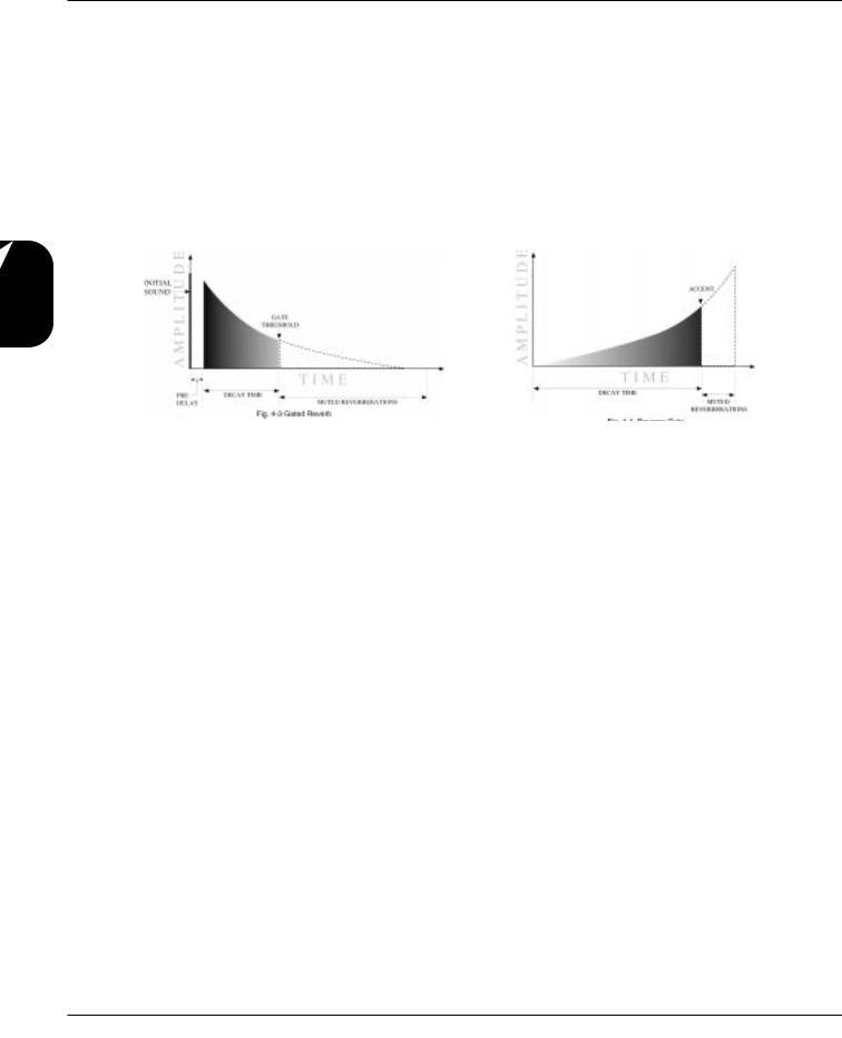
Section 3 - Editing Effects
Gated Reverbs - A true gated reverb is simply a reverb followed by a gate. In the GSP-2101 Artist, this combination is emulated in a single Module. Gates usually include adjustable thresholds to set the point at which the reverberations will be gated (cut off). In fig. 3-7,you can see that reverberations occurring at a level below the gate threshold cutoff point are muted. This causes the reverb to decay for a specific amount of time (determined by the gate time), then it is cut off abruptly.
Gated reverbs are most commonly used on percussion, but there are other ways to employ the unique sound they produce. For instance, using a BUILD envelope shape, a reverse reverb effect can be accomplished. Rather than decaying out to be cut off by the gate, a reverse gate builds for a specific amount of time, and is cut off by the gate. Reverse envelopes are similar in sound to playing a record backwards. Fig. 3-8 shows how it works.
Effects Editing
Fig 3-7 |
Fig 3-8 |
The accent point shown in the diagram allows placement of the actual sound, either before or after the gate has cut off the reverberation.
The GSP-2101 Artist offers three different envelope shapes in the gated reverb Modules: RAMP DOWN, FLAT, and RAMP UP. RAMP DOWN is a standard gated reverb envelope, with a linear decay to the cutoff point. In most applications, the RAMP DOWN envelope doesn't need an accent point, although it can produce some interesting unnatural sounds. In instances where an accent point is not needed, simply turn down the left and right REVERB ACCENT LVL parameters.
Using a FLAT envelope shape, the reverberation neither decays nor builds, but remains at a constant level for a specified amount of time (determined by the setting of DECAY TIME). This shape is particularly useful for short, percussive sounds.
RAMP UP allows creation of dramatic reverse gate reverb effects, with placement of the accent point permitted within 50 milliseconds before or after the end of DECAY TIME. Gated reverbs can be found in the <REVERB> library, and their parameters are as follows:
Effect On / Off: Turns the Module on or off. When the Module is turned off, its
Parameters are not displayed and signal will not continue to pass through the module.
To see the Parameters, you must turn the Module on.
Pre-Delay Time : Sets the amount of time before the reverberations are heard.
Adjustable from 0 to 100 milliseconds.
Decay Time: Controls the amount of time before the gate cuts off the reverberations.
Variable from 50 to 1000 milliseconds.
Envelope Shape: Sets the shape of the reverberation envelope (DECAY, FLAT, or
BUILD).
26 |
GSP-2101 Artist Owner’s Manual |

Section 3 - Editing Effects
Rvrb StereoBlend: Appears in stereo Modules only. Controls the amount of reverberation from the left side of the stereo sound field that is heard in the right side (and viceversa). Ranges from 0 to 100.
Diffusion: Controls the smoothness of the reverberations. Variable from 1 to 10.
LPF Frequency: Sets the frequency below which reverberations will be heard. Adjustable from 25Hz to 20kHz.
Accent Dly: Allows placement (in time) of the actual sound, between 50 milliseconds before or 50 milliseconds after the reverb has been gated.
Accent Level Left: Controls the level of the accent in the left channel. Variable from 0 to 100.
Accent Level Right: Controls the level of the accent in the right channel. Variable from 0 to 100.
Reverb Level Left: Sets the overall output level of the reverberations in the left channel. Variable from 0 to 100.
Reverb Level Right: Sets the overall output level of the reverberations in the right channel. Variable from 0 to 100.
[Dly/Smp] FX Library
Module Name |
Module Abbrv. |
Description |
Mono Delay x.x Sec |
Dly |
Mono in/out 1-tap digital delay |
|
|
|
Stereo Delay x.x Sec |
SDly |
Stereo input/output 1-tap digital delay |
2 Tap Delay x.x Sec |
2TDly |
Mono input 2-tap digital delay |
4 Tap Delay x.x Sec |
4TDly |
Mono input 4-tap digital delay |
Modulated Delay |
MDly |
Mono input/output digitally pitch-modulated delay |
Stereo Modulated Delay |
SMDly |
Stereo input/output digitally pitch-modulated delay |
|
|
|
Sampler x.x Seconds |
Smpl |
Mono sampler Module |
|
|
|
St. Sampler x.x Seconds |
SSmpl |
Stereo sampler Module |
|
|
|
Delays - All the non-modulated delays in this group have the same basic Parameters for controlling the behavior of the Module. General Parameters include: DELAY ON/OFF, INPUT LEVEL, DELAY TIME, FEEDBACK and REPEAT HOLD. The only differences between them are in the number of taps available. The multi-tap delays also include independent delay time controls for each tap, with a feedback control on the last tap in the series.
The Modulated Delays are a DigiTech exclusive that allow you to modulate the pitch of the delay repeats. They are similar in most respects to the rest of the delay family, but include an LFO modulation section like a chorus Module. The overall effect is that modulation is not heard in the signal until the delays begin repeating.
Editing Effects
GSP-2101 Artist Owner’s Manual |
27 |

Effects Editing
Section 3 - Editing Effects
Each delay Module has a number that immediately follows the name. These numbers represent the amount of delay time in seconds available to each Module. For example, if the Module name shown in the display reads 4TDLY 0.5, you know that the Module is a 4-tap delay with a maximum of .5 seconds (or 500 milliseconds) of delay time available.
The available delay time ranges are 0.5 (500 milliseconds), 1.0 (1000 milliseconds), 2.0 (2000 milliseconds), and 5.0 (5000 milliseconds). Each Delay type appears once in each delay time range (with the exception of SDLY, which does not appear in the 5.0 category). Delay Parameters are as follows:
Effect On / Off: Turns the Module on or off. When the Module is turned off, its Parameters are not displayed, and signal will not continue to pass through the module. To see the Parameters, you must turn the Module on.
Delay Time (Tap #): Controls the delay time of the tap indicated in the display. If no tap number is shown, this Parameter controls the overall delay time of the Module. DELAY TIMEs are editable in two different ranges to give the most flexibility and accuracy in the least amount of scrolling time. If you turn the Data wheel when the cursor is in the hundred milliseconds position (one place to the right of the decimal), you will increase or decrease the delay time in increments of 100 milliseconds. Pressing the Parameter’s Function key moves the cursor to the third position to the right of the decimal point, or milliseconds position. Each click of the Data wheel from this position increases the delay time in single millisecond steps. Using this method of ranging allows you to scroll rapidly to large-value delay times without having to wait for the unit to scroll to it in single millisecond steps. Variable from 0.000 sec. to 5.000 sec.
Feedback (Tap #): Controls the amount of feedback, or number of repeats, in the delay line. In multi-tap delays, this Parameter controls the feedback amount of the last tap in the series. Variable from 0 (Off) to 100%. See fig. 3-9.
LFO Speed: Controls the speed of the modulation sweep. Variable from .06 Hz to 16.00 Hz. This Parameter appears only in Modulated Delays.
LFO Depth: Sets the sweep depth (intensity) of the delay modulation. Variable from 0.00 to 40.00 milliseconds. This Parameter appears only in Modulated Delays.
LFO Waveform Type: Controls the LFO (low-frequency oscillator) waveform pattern of the delay modulation effect. SINE produces a smooth sine wave-type modulation with even transitions in and out of turnaround points. TRIANGLE is a linear modulation effect, and ramps the pitch of the wave up and down with no slowing at turnaround points. LOGARITHMIC and EXPONENTIAL waveforms are more dramatic in their effect on the signal, producing a type of bouncy oscillation. This Parameter appears only in Modulated Delays.
Level: Controls the level of the delay Module. Variable from 1 to 100.
28 |
GSP-2101 Artist Owner’s Manual |
 Loading...