


536.88614
CRRFTSMRW
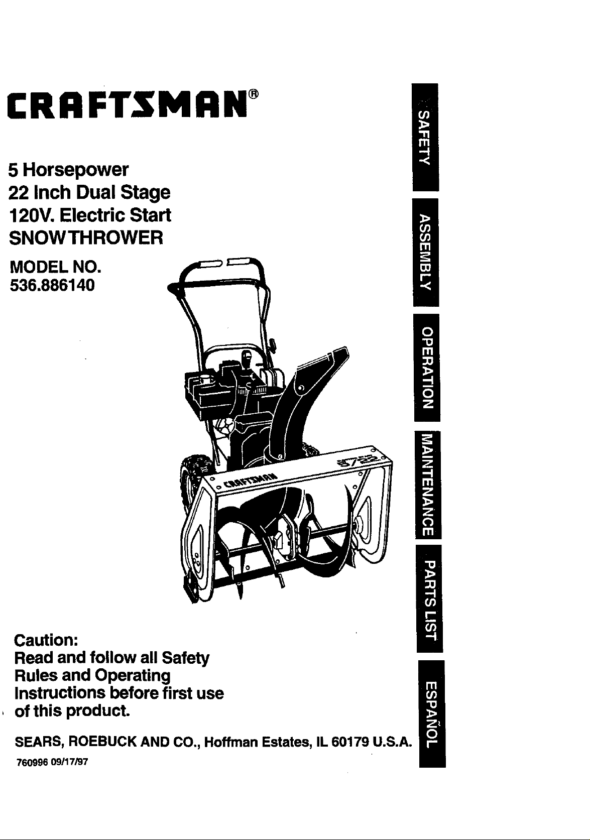
5 Horsepower
22 Inch Dual Stage
120V. Electric Start
SNOWTHROWER
MODEL NO.
536.886140
Caution:
Read and follow all Safety
Rules and Operating
Instructions before first use
, of this product.
SEARS, ROEBUCK AND CO., Hoffman Estates, IL 60179 U.S.A.
760996 09/17/97
Table of Contents 2 Service and Adjustments 17-21
Warranty 2 Storage 22
Safety Rules 2-4 Troubleshooting 23
Contents of Shipping Carton 4-5 Repair Parts 24-32
Assembly 5-8 Engine Repair Parts 33-37
Operation 8-14 Spanish(EspaSol) 38-63
Maintenance 14-16 Parts Ordering/Service Back Cover
LIMITED TWO-YEAR WARRANTY ON CRAFTSMAN SNOW THROWER
For two years from the date of purchase, when this Craftsman Snow Thrower is maintained,
lubricated, and tuned up according to the operating and maintenance instructions in the
owner's manual, Craftsman will repair, free of charge, any defect in material or workmanship.
If this Craftsman Snow Thrower is used for commercial or rental purposes, this warranty
applies for only 90 days from the date of purchase..
This warranty does not cover the following:
• Items which become wom during normal use, such as spark plugs, drive belts and
shear pins.
• Repairs necessary because of operator abuse or negligence, including bent crank
shafts and the failure to maintain the equipment according to the instructions con-
tained in the owner's manual.
WARRANTY SERVICE IS AVAILABLE BY RETURNING THE CRAFTSMAN SNOW
THROWER TO THE NEAREST CRAFTSMAN SERVICE CENTER/DEPARTMENT IN THE
UNITED STATES. THIS WARRANTY APPLIES ONLY WHILE THIS PRODUCT IS IN USE
IN THE UNITED STATES.
This warranty gives you specific legal rights, and you may also have other rights which may
vary from state to state.
Sears, Roebuck and Co., D817WA, Hoffman Estates, IL 60179
/_ Look for this symbol to point out Important safety precauUons. It means--
Z_ CAUTION: Always disconnect spark
plug wire and place wire where it cannot
contact spark plug to prevent accidental
starting when setting-up, transporting,
adjusting or making repairs.
IMPORTANT: Safety standards require
operator presence controls to minimize the
risk of injury. Your snow thrower is
equipped with such controls. Do not attempt
to defeat the function of the operator
presence control under any circumstances.
ATTENTION!I! Become alertll! Your safety is involved,
TRAINING
1. Read the operator's manual carefully.
Be thoroughly familiar with the controls
and the proper use of the snow throws
Know how to stop the snow thrower ar
disengage the controls quickly.
2. Never allow children to operate the sr
thrower and keep them away while it
operating. Never allow adults to oper
the snow thrower without proper inst_
tion. Do not carry passengers.
3. Keep the area of operation clear of f
persons, particularly small children
California Proposition 65
WARNING:Tho
pets. °
4. Exercise caution to avoid slipping c
falling, especially when operating I,
reverse.
PREPARATION
.
Thoroughly inspect the area whw
snow thrower is to be used an_
all doormats, sleds, boards, wit
other foreign objects.
,
Disengage all clutches before starting
the engine (motor).
3.
Do not operate the snow thrower
without wearing adequate winter outer
garments.Wear footwear that will
improve footing on slippery surfaces.
.
Handle fuel with care; it is highly
flammable.
(a) Use an approved fuel container.
(b) Never remove fuel tank cap or add
fuel to a running engine or hot
engine.
(c) Fill fuel tank outdoors with
extreme care. Never fill fuel tank
indoors.
(d) Replace fuel tank cap securely
and wipe up spilled fuel.
(e) Never store fuel or snow thrower
with fuel in the tank inside of a
building where fumes may reach
an open flame or spark.
(f) Check fuel supply before each
use, allowing space for expansion
as the heat of the engine (motor)
and/or sun can cause fuel to
expand.
5. Use extension cords and receptacles
as specified by the manufacturer for all
snow throwers with electric drive
motors or electric starting motors.
6. Adjust the snow thrower height to clear
gravel or crushed reck surfaces.
7. Never attempt to make any adjust-
ments while the engine (motor) is
running (except when specifically
recommended by the manufacturer).
8. Let engine (motor) and snow thrower
adjust to outdoor temperatures before
starting to clear snow.
9. Always wear safety glasses or eye
shields during operation or while
performing an adjustment or repair to
protect eyes from foreign objects that
may be thrown from the snow thrower.
OPERATION
1. Do not operate this machine if you are
taking drugs or other medication which
can cause drowsiness or affect your
ability to operate this machine.
2. Do not use this machine if you are
mentally or physically unable to
operate this machine safely.
3. Do not put hands or feet near or under
rotating parts. Keep c!ear of the
discharge opening at all times.
4. Exercise extreme caution when oper-
ating on or crossing gravel drives,
walks, or roads. Stay alert for hidden
hazards or traffic.
5. After striking a foreign object, stop the
engine (motor), remove the wire from
the spark plug, disconnect th e cord on
electric motors, thoroughly inspect the
snow thrower for any damage, and
repair the damage before
operating the snow thrower.
6. Ifthe snow thrower should start to
vibrate abnormally, stop the (motor)
and check immediately for the cause.
Vibration is generally a warning of
trouble.
7. Stop the engine (motor) whenever you
leave the operating position, before
unclogging the auger/impeller housing
or discharge guide, and when making
any repairs, adjustments, or inspec-
tions.
8. When cleaning, repairing, or inspecting,
make certain the auger/impeller and all
moving parts have stopped. Disconnect
the spark plug wire and keep the wire
away from the plug to prevent acciden-
tal starting.
9. Take all possible precautions when
leaving the snow thrower unattended.
Disengage the auger/impeller, stop
engine, and remove key.
10. Do not run the engine indoors, except
when startingthe engine and for
transporting the snow thrower in or out
of the building. Open the outside doors;
exhaust fumes are dangerous (contain-
ing CARBON MONOXIDE, an ODOR-
LESS and DEADLY GAS).
11. Do not clear snow across the face of
slopes. Exercise caution when changing
direction on slopes. Do not attempt to
clear steep slopes.
12. Never operate the snow thrower without
proper guards, plates or other safety
protective devices in place.
13. Never operate the snow thrower near
glass enclosures, automobiles, window
wells, drop-offs, and the like without
proper adjustment of the snow
discharge angle. Keep children and
pets away.
14. Do not overload the machine capacity
by attempting to clear snow at too fast
a rate.
15. Never operate the snow thrower at high
transport speeds on slippery surfaces.
Look behind and use care when
backing.
16. Never direct discharge at bystanders or
allow anyone in front of the snow
thrower.
17. Disengagepowertotheauger/impeller
whensnowthroweristransportedor
not inuse.
18, Useonlyattachmentsandaccessories
approvedbythemanufacturerofthe
snowthrower(suchastirechains,
electricstartkits,etc.).
19. Neveroperatethesnowthrower
withoutgoodvisibilityorlight.Always
be sureofyourfooting,andkeepa
firm holdonthehandles.Walk;never
run.
MAINTENANCE ANDSTORAGE
1. Check shear bolts and other bolts
frequently for proper tightness to be
sure the snow thrower is in safe
working condition.
2. Never store the snow thrower with fuel
in the fuel tank inside a building where
ignition sources are present such as
hot water and space heaters, clothes
dryers, and the like. Allow the engine to
cool before storing inany enclosure.
3. Always refer to operator's manual
instructions for important details if the
snow thrower is to be stored for an
extended period.
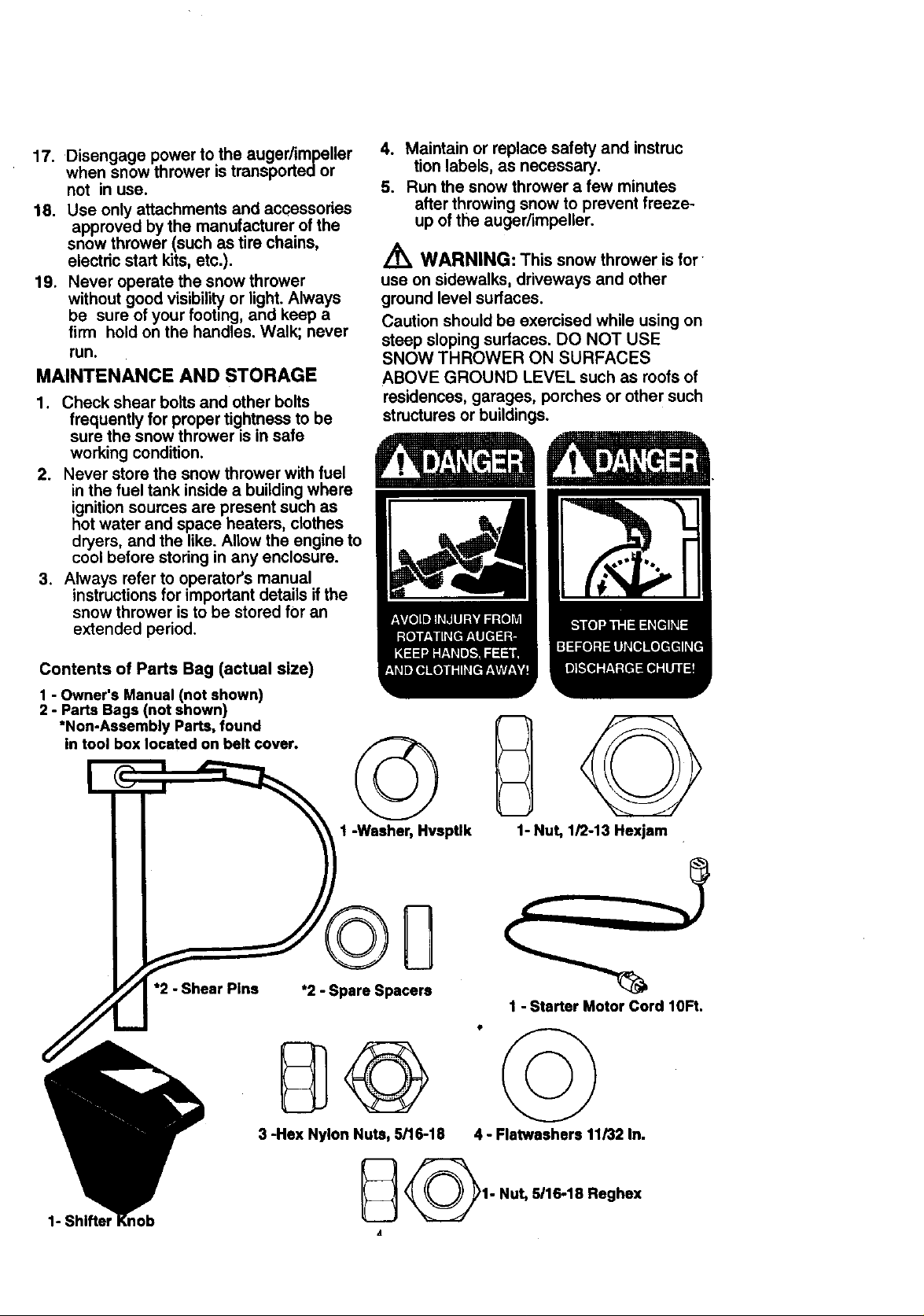
4. Maintain or replace safety and instruc
tion labels, as necessary.
5. Run the snow thrower a few minutes
after throwing snow to prevent freeze-
up of the auger/impeller.
A
WARNING: This snow thrower is for
use on sidewalks, driveways and other
ground level surfaces.
Caution should be exercised while using on
steep sloping surfaces. DO NOT USE
SNOW THROWER ON SURFACES
ABOVE GROUND LEVEL such as roofs of
residences, garages, porches or other such
structures or buildings.
Contents of Parts Bag (actual size)
1 - Owner's Manual (not shown)
2 - Parts Bags (not shown)
*Non-Assembly Parts, found
in tool box located on belt cover.
*2 - Shear Pins
©
1 -Washer, Hvsptlk 1- Nut, 1/2-13 Hexjam
*2 - Spare Spacers
1 - Starter Motor Cord lOFt.
1- Shifter I
3 -Hex Nylon Nuts, 5/16-18
_1- Nut, 5/16-18 Reghex
A
4 - Flatwaahers 11/32 In.
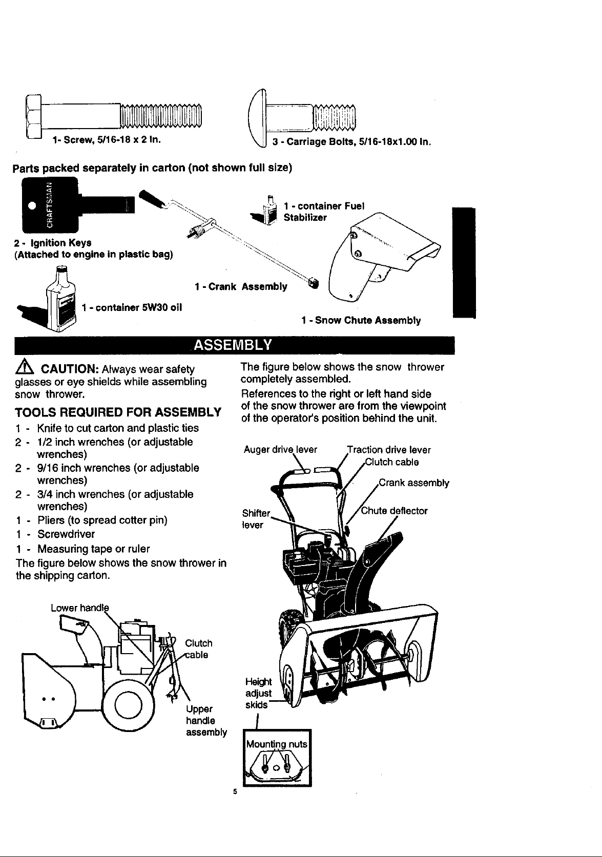
1- Screw, 5/16-18 x2 In.
_ 5116-18x1.00 In.
Parts packed separately in carton (not shown full size)
2 - Ignition Keys
(Attached to engine in plastic bag)
1 - Crank Assembly
1 - container 5W30 oil
1 - container Fuel
Stabilizer
1 - Snow Chute Assembly
CAUTION: Always wear safety
glasses or eye shields while assembling
snow thrower.
TOOLS REQUIRED FOR ASSEMBLY
1 - Knife to cut carton and plastic ties
2 - 1/2 inch wrenches (or adjustable
wrenches)
2 - 9/16 inch wrenches (or adjustable
wrenches)
2 - 3/4 inch wrenches (or adjustable
wrenches)
t - Pliers (to spread cotter pin)
1 - Screwddver
1 - Measuring tape or ruler
The figure below shows the snow thrower in
the shipping carton.
Lower hand!
=_ Clutch
The figure below shows the snow thrower
completely assembled.
References to the right or left hand side
of the snow thrower are from the viewpoint
of the operator's position behind the unit.
Auger drive lever
cable
ly
lever
able
e
assembly
Height
adjust
skids
/
5
TO REMOVE SNOW THROWER
FROM CARTON
• Locate and remove container of 5W30 oil.
• Locate all parts packed separately and
remove from the carton.
NOTE: Place fuel stabilizer in a safe place
until needed for storage.
• Remove and discard the packing material
from around the snow thrower.
• Cut all four comers of the carton from top
to bottom and lay the panels flat.
• Roll the snow thrower off the carton by
pulling on the lower handle. CAUTION:
DO NOT back over cables.
• Remove the packing material from
handle assembly and plastic protector on
top of auger housing.
• Cut ties securing the clutch control cables
to the lower handle and lay cables back
away from the motor frame.
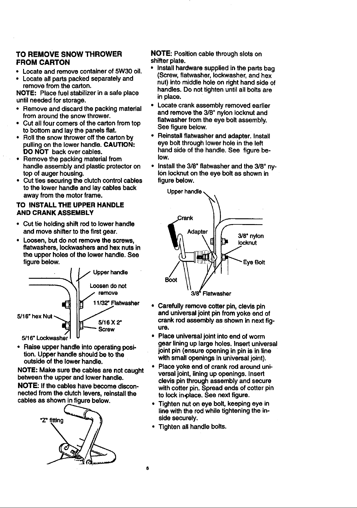
TO INSTALL THE UPPER HANDLE
AND CRANK ASSEMBLY
• Cut tie holding shift rod to lower handle
and move shifter to the first gear.
• Loosen, but do not remove the screws,
flatwashers, Iockweshers and hex nuts in
the upper holes of the lower handle. See
figure below.
Upper handle
NOTE: Position cable through slots on
shifter plate.
• Install hardware supplied in the parts bag
(Screw, flatwasher, Iockwasher, and hex
nut) into middle hole on right hand side of
handles. Do not tighten until all bolts are
in place.
• Locate crank assembly removed earlier
and remove the 3/8" nylon Iocknut and
flatwasher from the eye bolt assembly.
See figure below.
• Reinstall flatwasher and adapter. Install
eye bolt through lower hole in the left
hand side of the handle. See figure be-
low.
• Install the 3/8" flatwasher and the 3/8" ny-
lon lock,nut on the eye bolt as shown in
figure below.
3/8" nylon
Iocknut
e Bolt
Loosen do not
remove
11/32_Ratwasher
5/16" hex Nut .-,
5/16 X 2"
5/16"
• Raise upper handle into operating posi-
tion. Upper handle should be to the
outside of the lower handle.
NOTE: Make sure the cables are not caught
between the upper and lower handle.
NOTE: Ifthe cables have become discon-
nected from the clutch levers, reinstall the
cables as shown in figure below.
"Z' fitting
Ratwssher
Carefully remove cotter pin, clevis pin
and universal joint pin from yoke end of
crank rod assembly as shown in next fig-
ure.
• Place universal joint into end of worm
gear lining up large holes. Insert universal
joint pin (ensure opening in pin is in line
with small openings in universal joint).
• Place yoke end of crank rod around uni-
versal joint, lining up openings. Insert
clevis pin through assembly and secure
with cotter pin. Spread ends of cotter pin
to lock in,place. See next figure.
• Tighten nut on eye bolt, keeping eye in
line with the rod while tightening the in-
side securely.
• Tighten all handle bolts.
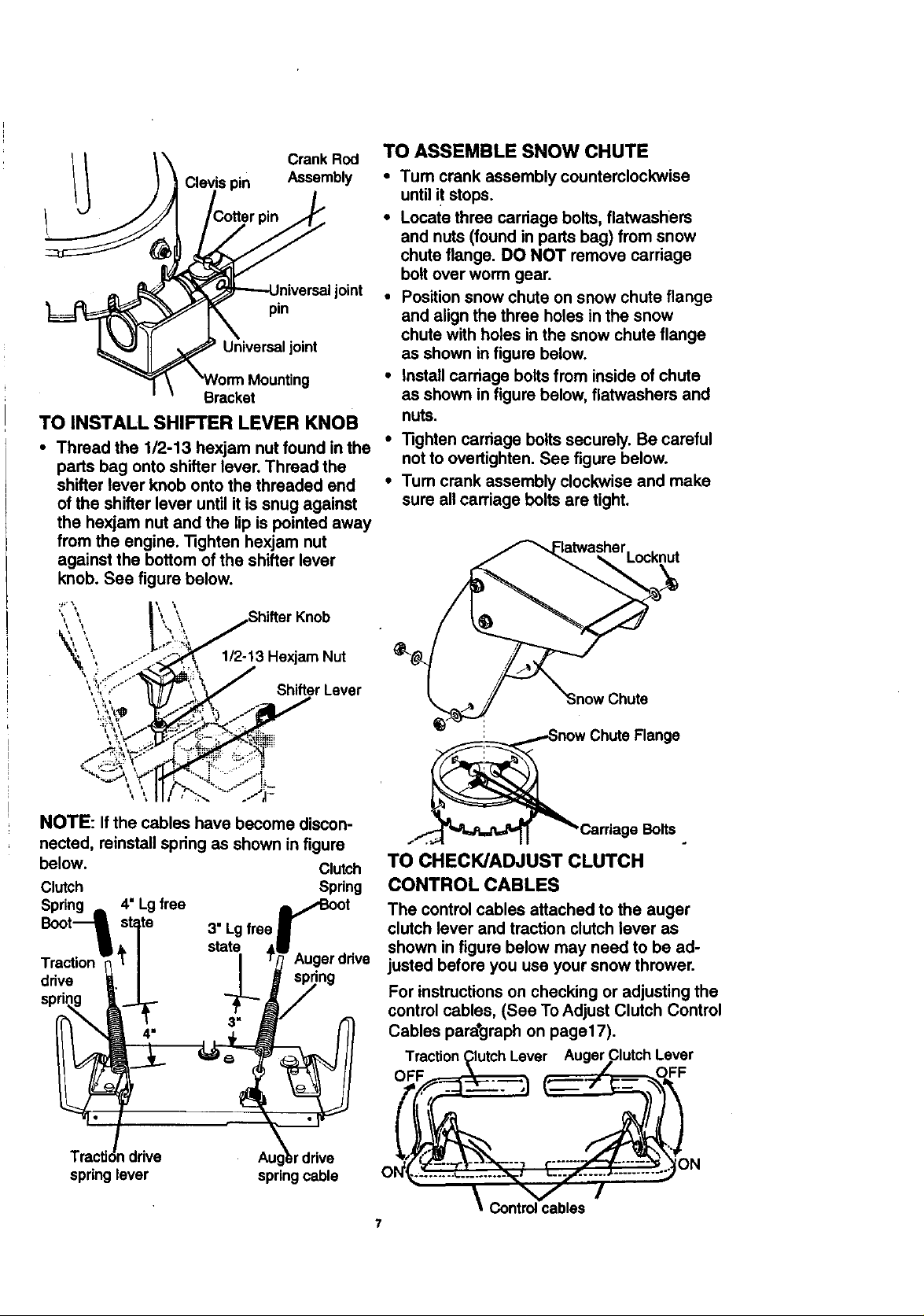
Crank Rod
Assembly
joint
pin
Universaljoint
Bracket
TO INSTALL SHIFTER LEVER KNOB
• Thread the 1/2-13 hexjam nut found in the
parts bag onto shifter lever. Thread the
shifter lever knob onto the threaded end
of the shifter lever until it is snug against
the hexjam nut and the lip is pointed away
from the engine. Tighten hexjam nut
against the bottom of the shifter lever
knob. See figure below.
TO ASSEMBLE SNOW CHUTE
•Tum crank assembly counterclockwise
until it stops.
• Locate three carriage bolts, flatwashers
and nuts (found in parts bag) from snow
chute flange. DO NOT remove carriage
bolt over worm gear.
• Position snow chute on snow chute flange
and align the three holes in the snow
chute with holes in the snow chute flange
as shown in figure below.
• install carriage bolts from inside of chute
as shown in figure below, flatwashers and
nuts.
• Tighten carriage bolts securely. Be careful
not to overtighten. See figure below.
•Tum crank assembly clockwise and make
sure all carriage bolts are tight.
Flange
NOTE: If the cables have become discon- Bolts
nected, reinstall spring as shown in figure
below. Clutch TO CHECK/ADJUST CLUTCH
Clutch Spring CONTROL CABLES
Spring ,,, 4" Lg free _IBoot The control cables attached to the auger
Boot1 state 3" Lgfree J clutch lever and traction clutch lever as
_ / state ,11 _ . shown in figure below may need to be ad-
Traction _'[ | I T_ Augerdnve justed before you use your snow thrower.
.va I / _J s_ng
spring " For instructions on checking or adjusting the
Cables para*graph on paget7).
Traction Clutch Lever Auger Clutch Lever
control cables, (See To Adjust Clutch Control
TracUdndrive Augkr drive "N_.......;..:.........,_ ...... )N
springlever springcable O .......... ._÷..... v_ _ .... /" .......... ""
7
\
Controlcables
HOW TO SET UP YOUR SNOW
THROWER
• Your snow thrower is equipped with height
adjust skids (see second figure on page 5)
on the outside of the auger housing. To
adjust the skid height for different
conditions, (see To Adjust Skid Height
paragraph on page 17).
,/ CHECKLIST
Before you operate your new snow
thrower, toensure that you receive the
best performance and satisfaction from this
quality product, please review the following
checklist:
,/ All assembly instructions have been
completed.
,/ The discharge chute rotates freely.
/ No remaining loose parts in carton.
While learning how to use your snow
thrower, pay extra attention to the following
important items: i
,// Engine oil is at proper level.
,/,/ Make sure gas tank is filled properly
with clean, fresh, unleaded gasoline.
,/,/ Become familiar with all controls-their
location and function. Operate controls
before starting engine.
Auger Drive Lever - Starts and stops the
auger and impeller (snow gathering and
throwing).
Traction Drive Lever - Propels the snow
thrower forward and in reverse.
Speed Shifter Lever - Selects the speed of
snow thrower (6 speeds forward and 2
speeds reverse).
Crank Assembly - Changes the direction of
snow throwing through the discharge chute.
Chute Deflector - Changes the distance
the snow is thrown.
Discharge Chute - Changes the direction
the snow is thrown.
Height Adjust Skids - Adjusts the ground
clearance of the auger housing.
Ignition Key - Must be inserted to start the
engine.
Recoil Starter Handle - Starts the engine
manually.
Choke Control - Used to start a cold en-
gine.
Primer Button - Injects fuel directly into the
carburetor manifold for fast starts in cold
weather.
Throttle Control - Controls the engine
speed.
Electric Starter Button - Used to startthe
engine using the 120 V electric starter.
Shear Bolt - Shear bolts are designed to
break (to protect the machine) if an object
becomes lodged in the auger housing. Use
of a harder bolt will destroy the protection
provided by the shear bolt.
Toolbox- Spare shear pins and spacers 0
located in toolbox.
8
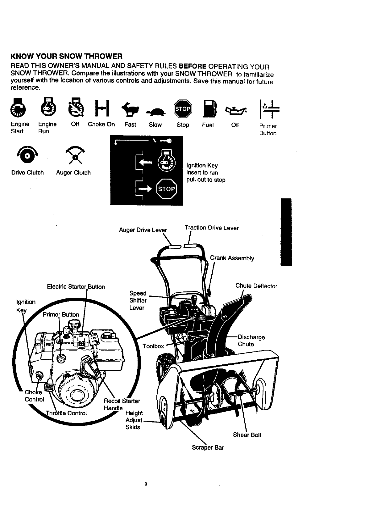
KNOW YOUR SNOW THROWER
READ THIS OWNER'S MANUAL AND SAFETY RULES BEFORE OPERATING YOUR
SNOW THROWER. Compare the illustrations with your SNOW THROWER to familiarize
yourself with the location of various controls and adjustments. Save this manual for future
reference.
Engine Engine Off Choke On Fast Slow Stop Fuel Oil Primer
Start Run Button
Ignition Key
Drive Clutch Auger Clutch
Auger Drive Lever Traction Drive Lever
insert to run
pull out to stop
IgniUon
Control
Crank Assembly
Chute Deflector
Speed
Shifter
Lever
Chute
Skids
Shear Bolt
The operation of any snow thrower can re-
sult in foreign objects being thrown into the
eyes, which can result in severe eye dam-
age. Always wear safety glasses or eye
shields while operating the snow thrower.
We recommend standard safety glasses or
a wide vision safety mask for over your
glasses, available at Craftsman Retail
Stores or Service Centers.
L_ CAUTION: Read owner's manual
before operating machine. Never direct
discharge toward bystanders. Release the
auger control bar and stop the engine
before unclogging discharge chute or auger
housing and before leaving the machine,
HOWTO USEYOUR SNOW
THROWER
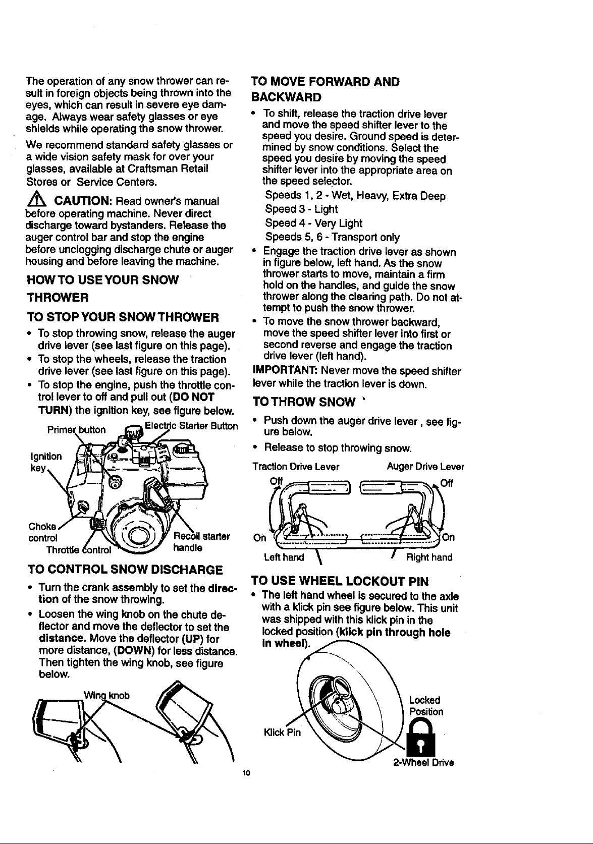
TO STOP YOUR SNOW THROWER
• To stop throwing snow, release the auger
drive lever (see last figure on this page).
• To stop the wheels, release the traction
drive lever (see last figure on this page).
• To stop the engine, push the throttle con-
trol lever to off and pull out (DO NOT
TURN) the ignition kay, see figure below.
button c Starter Button
Ignition
TO MOVE FORWARD AND
BACKWARD
• To shift, release the traction drive lever
and move the speed shifter lever to the
speed you desire. Ground speed is deter-
mined by snow conditions. Select the
speed you desil'e by moving the speed
shifter lever into the appropriate area on
the speed selector.
Speeds 1,2 - Wet, Heavy, Extra Deep
Speed 3 +Light
Speed 4 - Very Light
Speeds 5, 6 - Transport only
• Engage the traction drive lever as shown
in figure below, left hand. As the snow
thrower starts to move, maintain a firm
hold on the handles, and guide the snow
thrower along the clearing path. Do not at-
tempt to push the snow thrower.
• To move the snow thrower backward,
move the speed shifter lever into first or
second reverse and engage the traction
drive lever (left hand).
IMPORTANT: Never move the speed shifter
lever while the traction lever is down.
TOTHROW SNOW '
• Push down the auger drive lever, see fig-
ure below.
• Release to stop throwing snow.
TractionDrive Lever Auger Ddve Lever
Off Off
control ;tarter On
handle
TO CONTROL SNOW DISCHARGE
• Turn the crank assembly to set the direc-
tion of the snow throwing.
• Loosen the wing knob on the chute de-
flector and move the deflector to set the
distance. Move the deflector (UP) for
more distance, (DOWN) for less distance.
Then tighten the wing knob, see figure
below.
knob
TO USE WHEEL LOCKOUT PIN
• The left hand wheel is secured to the axle
10
Lefthand Right hand
with a klick pin see figure below. This unit
was shipped with this klick pin in the
locked position (kllck pin through hole
In wheel).
Locked
Position
KlickPin
2-Wheel Ddve
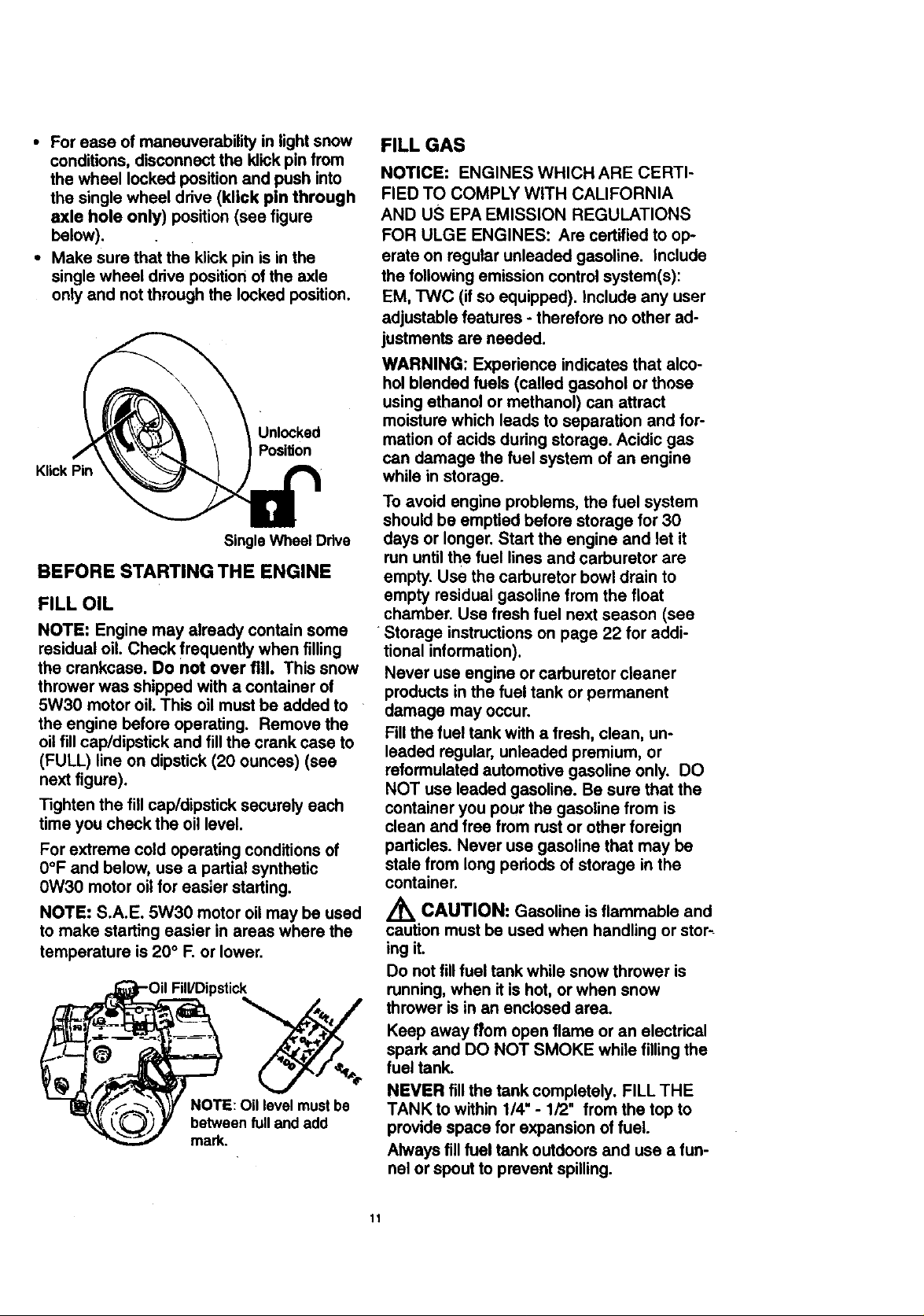
• For ease of maneuverability in light snow
conditions, disconnect the klick pin from
the wheel locked position and push into
the single wheel drive (klick pin through
axle hole only) position (see figure
below).
• Make sure that the klick pin is in the
single wheel drive position of the axle
only and not through the locked position.
Unlocked
Position
KlickPin
Single Wheel Drive
BEFORE STARTING THE ENGINE
FILL OIL
NOTE: Engine may already contain some
residual oil. Check frequently when filling
the crankcase. Do not over fill. This snow
thrower was shipped with a container of
5W30 motor oil. This oil must be added to
the engine before operating. Remove the
oil fill cap/dipstick and fill the crank case to
(FULL) line on dipstick (20 ounces) (see
next figure).
Tighten the fillcap/dipsticksecurelyeach
time you checkthe oil level.
For extreme cold operating conditions of
0°F and below, use a partial synthetic
0W30 motor oil for easier starting.
NOTE: S.A.E. 5W30 motor oil may be used
to make starting easier in areas where the
temperature is 20 ° F. or lower.
Fill/Dipstick
NOTE: Oil level must be
between full andadd
mark.
FILL GAS
NOTICE: ENGINES WHICH ARE CERTI-
FIED TO COMPLY WITH CALIFORNIA
AND US EPA EMISSION REGULATIONS
FOR ULGE ENGINES: Are certified to op-
erate on regular unleaded gasoline. Include
the following emission control system(s):
EM, TWC (if so equipped). Include any user
adjustable features - therefore no other ad-
justmants are needed.
WARNING: Experience indicates that alco-
hol blended fuels (called gasohol or those
using ethanol or methanol) can attract
moisture which leads to separation and for-
mation of acids during storage. Acidic gas
can damage the fuel system of an engine
while in storage.
To avoid engine problems, the fuel system
should be emptied before storage for 30
days or longer. Start the engine and let it
run until the fuel lines and carburetor are
empty. Use the carburetor bowl drain to
empty residual gasoline from the float
chamber. Use fresh fuel next season (see
•Storage instructions on page 22 for addi-
tional information).
Never use engine or carburetor cleaner
products in the fuel tank or permanent
damage may occur.
Fill the fuel tank with a fresh, clean, un-
leaded regular, unleaded premium, or
reformulated automotive gasoline only. DO
NOT use leaded gasoline. Be sure that the
container you pour the gasoline from is
clean and free from rust or other foreign
particles. Never use gasoline that may be
stale from long periods of storage in the
container.
/_ CAUTION: Gasoline is flammable and
caution must be used when handling or stor_
ing it.
Do not fill fuel tank while snow thrower is
running, when it is hot, or when snow
thrower is in an enclosed area.
Keep away from open flame or an electrical
spark and DO NOT SMOKE while filling the
fuel tank.
NEVER fill the tank completely. FILL THE
TANK to within 1/4" - 1/2" from the top to
provide space for expansion of fuel.
Always fill fuel tank outdoors and use a fun-
nel or spout to prevent spilling.
11
Make sure to wipe up any spilled fuel be-
fore starting the engine.
Store gasoline in a clean, approved con-
tainer and keep the cap in place on the
container.
TO STOP ENGINE
• To stop engine, move the throttle control
lever to O (STOP) position and remove
key. Keep the key in a safe place. The
engine will not start without the key.
NOTE: DO NOT turn key.
TO START ENGINE (Electric Starter)
Be sure that the engine has sufficient oil.
The snow thrower engine is equipped with a
120 volt A.C. electric starter and recoil
starter. Before starting the engine, be cer-
tain that you have read the following infor-
mation:
COLD START
• Be sure the auger drive and traction drive
levers are in the disengaged (released)
position.
• Move the throttle control to '_ (FAST)
position. See figure on page 9.
• Remove the keys from the plastic bag.
Insert one key into the ignition slot. Be
sure it snaps into place. DO NOT TURN
KEY. Keep the second key in a safe
place.
' Rotate the choke knob clockwise to H
choke ON position. See figure on page 9.
• Connect the power cord to the switch box
on the engine.
Z_ CAUTION: This starter is equipped
with a three-wire power cord and plug
and is designed to operate on 120 volt AC
household current. It must be properly
grounded at all times to avoid the possibility
of electrical shock, which may be injurious
to operator. Follow all instructions carefully
as set forth in the "To Start Engine' section.
Determine that your house wiring is a three-
wire grounded system. Ask a licensed elec-
trician if you are not sure. If your house wire
system is not a three-wire system, do not
use this electric starter under any condi-
tions. If your system is grounded and a
three-hole receptacle is not available at the
point your starter will normally be used, one
should be installed by a licensed electrician.
When connecting 120 volt AC power cord,
always connect the cord to the switch box
on the engine first, then plug the other end
into the three-hole grounded receptacle.
When disconnecting power cord, allVays
unplug the end in the three-hole grounded
receptacle first.
• Plug the other end of the power cord into
a three-hole, grounded 120 volt A.C.
receptacle.
• Push the primer button while covering the
vent hole as follows: (Remove finger
from primer button between primes).
See figure on page 9 for location.
Do not prime iftemperature is above
5O°F.
Two times if temperature is 50°F to 15°F.
Four times if temperature is below 15°F.
• Pt_sh down on the starter button until the
engine starts. Do not crank for more than
10 seconds at a time. This electric starter
is thermally protected. If overheated it will
stop automatically and can be restarted
only when it has cooled to a safe tem-
perature (a wait of about 5 to 10 minutes
is required).
• When the engine starts, release the
starter button and move choke lever to
_1/2 choke" position. When engine runs
smoothly, move choke lever to "No
Choke" Position.
• Disconnect the power cord from the
receptacle first and then from the switch
box on engine.
NOTE: Allow the engine to warm up for sev-
eral minutes before blowing snow in tem-
peratures below 0°F.
• Run the engine at full throttle '_p (FAST)
when throwing snow.
TO STOP ENGINE
• To stop engine, move the throttle control
lever to O (STOP) position and remove
key. Keep the key in a safe place. The
engine will not start without the key.
NOTE: DO NOT turn key.
TO START ENGINE (Recoil Starter)
Be sure that the engine has suff=clent oral.
The snow thrower engine is equipped with
a recoil starter. Before starting the engine,
be certain that you have read the following
information:
t2
 Loading...