


 Loading...
b
Maintenance and Service
Guide
Compaq Presario V6000 Notebook PC
Document Part Number: 416630-003
April 2007
This guide is a troubleshooting reference used for maintaining and servicing the computer. It provides comprehensive information on identifying computer features, components, and spare parts; troubleshooting computer problems; and performing computer disassembly procedures.
© Copyright 2006, 2007 Hewlett-Packard Development Company, L.P.
Microsoft, Windows, and Windows Vista are either trademarks or registered trademarks of Microsoft Corporation in the United States and/or other countries. Intel, Core, and Celeron are trademarks or registered trademarks of Intel Corporation or its subsidiaries in the United States and other countries and regions. Bluetooth is a trademark owned by its proprietor and used by Hewlett-Packard Company under license. SD Logo is a trademark of its proprietor. AMD, the AMD Arrow logo and combinations thereof are trademarks of Advanced Micro Devices, Inc.
The information contained herein is subject to change without notice. The only warranties for HP products and services are set forth in the express warranty statements accompanying such products and services. Nothing herein should be construed as constituting an additional warranty. HP shall not be liable for technical or editorial errors or omissions contained herein.
Maintenance and Service Guide
Compaq Presario V6000 Notebook PC
Third Edition: April 2007
First Edition: August 2006
Document Part Number: 416630-003

Safety warning notice
ÅWARNING: To reduce the possibility of heat-related injuries or of overheating the computer, do not place the computer directly on your lap or obstruct the computer air vents. Use the computer only on a hard, flat surface. Do not allow another hard surface, such as an adjoining optional printer, or a soft surface, such as pillows or rugs or clothing, to block airflow. Also, do not allow the AC adapter to contact the skin or a soft surface, such as pillows or rugs or clothing, during operation. The computer and the AC adapter comply with the user-accessible surface temperature limits defined by the International Standard for Safety of Information Technology Equipment (IEC 60950).

Contents
Contents
1 Product Description
1.1 Features . . . . . . . . . . . . . . . . . . . . . . . . . . . . . . . . . . . 1–2 1.2 Resetting the Computer. . . . . . . . . . . . . . . . . . . . . . . 1–4 1.3 Power management . . . . . . . . . . . . . . . . . . . . . . . . . . 1–5 1.4 External Components . . . . . . . . . . . . . . . . . . . . . . . . 1–6 1.5 Design overview . . . . . . . . . . . . . . . . . . . . . . . . . . . 1–22
2 Troubleshooting
2.1 Setup Utility in Windows XP . . . . . . . . . . . . . . . . . . 2–1
Using the Setup Utility . . . . . . . . . . . . . . . . . . . . . . . 2–1
Setup Utility Menus . . . . . . . . . . . . . . . . . . . . . . . . . 2–5
2.2 Setup Utility in Windows Vista . . . . . . . . . . . . . . . . 2–8
Using the Setup Utility . . . . . . . . . . . . . . . . . . . . . . . 2–8
Setup Utility Menus . . . . . . . . . . . . . . . . . . . . . . . . 2–11
2.3 Troubleshooting Flowcharts . . . . . . . . . . . . . . . . . . 2–15
Maintenance and Service Guide |
v |

Contents
3 Illustrated Parts Catalog
3.1 Serial Number Location . . . . . . . . . . . . . . . . . . . . . . 3–1
3.2 Computer Major Components. . . . . . . . . . . . . . . . . . 3–2
3.3 Display Assembly Components . . . . . . . . . . . . . . . 3–21
3.4 Mass Storage Devices . . . . . . . . . . . . . . . . . . . . . . . 3–23
3.5 Plastics Kit . . . . . . . . . . . . . . . . . . . . . . . . . . . . . . . 3–25
3.6 Miscellaneous . . . . . . . . . . . . . . . . . . . . . . . . . . . . . 3–27
3.7 Sequential Part Number Listing . . . . . . . . . . . . . . . 3–30
4 Removal and Replacement Preliminaries
4.1 Tools Required . . . . . . . . . . . . . . . . . . . . . . . . . . . . . 4–1 4.2 Service Considerations . . . . . . . . . . . . . . . . . . . . . . . 4–2 Plastic Parts . . . . . . . . . . . . . . . . . . . . . . . . . . . . . . . . 4–2 Cables and Connectors . . . . . . . . . . . . . . . . . . . . . . . 4–2 4.3 Preventing Damage to Removable Drives . . . . . . . . 4–3
4.4 Preventing Electrostatic Damage . . . . . . . . . . . . . . . 4–4 4.5 Packaging and Transporting Precautions . . . . . . . . . 4–5 4.6 Workstation Precautions . . . . . . . . . . . . . . . . . . . . . . 4–6 4.7 Grounding Equipment and Methods . . . . . . . . . . . . . 4–7
Maintenance and Service Guide |
vi |

Contents
5 Removal and Replacement Procedures
5.1 Serial Number . . . . . . . . . . . . . . . . . . . . . . . . . . . . . . 5–2
5.2 Disassembly Sequence Chart . . . . . . . . . . . . . . . . . . 5–3
5.3 Preparing the Computer For Disassembly . . . . . . . . 5–4
5.4 Hard Drive. . . . . . . . . . . . . . . . . . . . . . . . . . . . . . . . . 5–6
5.5 Computer Feet. . . . . . . . . . . . . . . . . . . . . . . . . . . . . 5–10
5.6 Memory Module . . . . . . . . . . . . . . . . . . . . . . . . . . . 5–11
5.7 RTC Battery . . . . . . . . . . . . . . . . . . . . . . . . . . . . . . 5–14
5.8 Mini Card Module. . . . . . . . . . . . . . . . . . . . . . . . . . 5–15
5.9 Optical Drive. . . . . . . . . . . . . . . . . . . . . . . . . . . . . . 5–20
5.10 Switch Cover. . . . . . . . . . . . . . . . . . . . . . . . . . . . . 5–22
5.11 Keyboard. . . . . . . . . . . . . . . . . . . . . . . . . . . . . . . . 5–25
5.12 Power Button Board . . . . . . . . . . . . . . . . . . . . . . . 5–29
5.13 Display Assembly . . . . . . . . . . . . . . . . . . . . . . . . . 5–31
5.14 Top Cover . . . . . . . . . . . . . . . . . . . . . . . . . . . . . . . 5–42
5.15 Audio Board . . . . . . . . . . . . . . . . . . . . . . . . . . . . . 5–48
5.16 Bluetooth Module . . . . . . . . . . . . . . . . . . . . . . . . . 5–50
5.17 ExpressCard Assembly . . . . . . . . . . . . . . . . . . . . . 5–52
5.18 USB/Power Connector Board . . . . . . . . . . . . . . . . 5–55
5.19 System Board . . . . . . . . . . . . . . . . . . . . . . . . . . . . 5–57
5.20 Fan/Heat Sink Assembly. . . . . . . . . . . . . . . . . . . . 5–61
5.21 Processor . . . . . . . . . . . . . . . . . . . . . . . . . . . . . . . . 5–64
Maintenance and Service Guide |
vii |

Contents
6 Specifications
AScrew Listing
BBackup and Recovery in Windows XP
CBackup and Recovery in Windows Vista
DDisplay Component Recycling
EConnector Pin Assignments
FPower Cord Set Requirements
Index
viii |
Maintenance and Service Guide |
1
Product Description
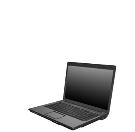
The Compaq Presario V6000 Notebook PC offers advanced modularity, Intel® Core™ Duo and Celeron® and AMD Turion™ 64 Mobile Technology and Mobile AMD Sempron™ processors, and extensive multimedia support.
Compaq Presario V6000 Notebook PC
Maintenance and Service Guide |
1–1 |

Product Description
1.1 Features
The following features vary by computer model:
■Intel Core Duo T7200 (2.00-GHz)
■Intel Core Duo T1350 (1.86-GHz)
■Intel Core Duo T5600 (1.83-GHz)
■Intel Core Duo T2350 (1.86-GHz)
■Intel Core Duo T2250 (1.73-GHz)
■Intel Core Duo T5500 (1.66-GHz)
■Intel Core Duo T5200 (1.66-GHz)
■Intel Core Duo T2060 (1.60-GHz)
■Intel Core Duo T2050 (1.60-GHz)
■Intel Celeron 440 (1.86-GHz)
■Intel Celeron 430 (1.73-GHz)
■Intel Celeron 420 (1.60-GHz)
■AMD Turion ML-60 (2.0-GHz)
■AMD Turion ML-56 (1.8-GHz)
■AMD Turion ML-52 (1.6-GHz)
■AMD Turion ML-50 (1.6-GHz)
■Mobile AMD Sempron 3500+ (1.8-GHz)
■Mobile AMD Sempron 3400+ (1.8-GHz)
■Mobile AMD Sempron 3200+ (1.6-GHz)
■15.4-inch WXGA (1280 × 768) TFT display with over 16.7 million colors, varying by computer model
■200-, 160-, 120-, 100-, 80-, 60-, and 40-GB high-capacity hard drive, varying by computer model
■256-MB DDR synchronous DRAM (SDRAM) at 667 MHz, expandable to 2.0 GB
■Microsoft® Windows Vista™ Business, Windows Vista Home Basic, and Windows® XP Professional
■Full-size Windows keyboard with embedded numeric keypad
1–2 |
Maintenance and Service Guide |

Product Description
TouchPad pointing device with on/off button and dedicated two-way scroll zone
Integrated 10/100 BASE-T Ethernet local area network (LAN) network interface card (NIC) with RJ-45 jack
Integrated high-speed 56K modem with RJ-11 jack
Integrated wireless support for Mini Card IEEE 802.11b and 802.11b/g WLAN device
Support for ExpressCard
External 90or 65-watt AC adapter with 3-wire power cord
6-cell or 12-cell Li-Ion battery
Stereo speakers with volume up and down buttons
Integrated microphones (select models only)
Support for the following optical drives:
DVD±RW/R and CD-RW Double-Layer Combo Drive with LightScribe
DVD±RW/R and CD-RW Double-Layer Combo Drive
DVD/CD-RW Combo Drive
Connectors:
Audio-in (microphone)
Audio-out (headphone)
Consumer infrared lens
Docking (select models only)
ExpressCard
External monitor
IEEE 1394 digital (select models only)
Memory Reader (select models only)
Power
RJ-11 (modem)
RJ-45 (network)
S-Video-out (select models only)
Universal Serial Bus (USB) v. 2.0
Maintenance and Service Guide |
1–3 |
Product Description
1.2 Resetting the Computer
If the computer you are servicing has an unknown password, follow these steps to clear the password. These steps also clear CMOS:
1.Prepare the computer for disassembly (refer to Section 5.3, “Preparing the Computer For Disassembly,” for more information).
2.Remove the real-time clock (RTC) battery (refer to Section 5.7, “RTC Battery,” for more information).
3.Wait approximately 5 minutes.
4.Replace the RTC battery and reassemble the computer.
5.Connect AC power to the computer. Do not reinsert any batteries at this time.
6.Turn on the computer.
All passwords and all CMOS settings have been cleared.
1–4 |
Maintenance and Service Guide |

Product Description
1.3 Power management
The computer comes with power management features that extend battery operating time and conserve power. The computer supports the following power management features:
■Standby
■Hibernation
■Setting customization by the user
■Hotkeys for setting the level of performance
■Battery calibration
■Lid switch standby/resume
■Power button
■Advanced Configuration and Power Management (ACPM) compliance
Maintenance and Service Guide |
1–5 |
Product Description
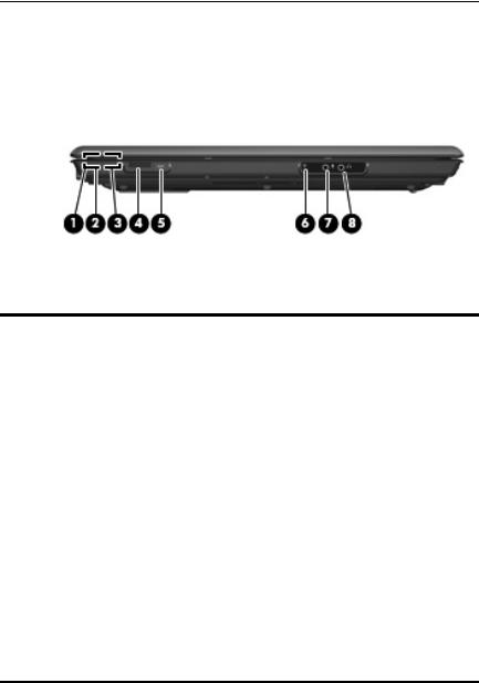
1.4 External Components
The external components on the front of the computer are shown below and described in Table 1-1.
Front Components
|
|
Table 1-1 |
|
|
Front Components |
|
|
|
Item |
Component |
Function |
|
|
|
1 |
Power light |
On: The computer is on. |
|
|
Blinking: The computer is in standby. |
|
|
Off: The computer is off or in hibernation. |
|
|
|
2 |
Battery light |
On: A battery is charging. |
|
|
Blinking: A battery that is the only available |
|
|
power source has reached a low-battery |
condition. When the battery reaches a critical low-battery condition, the battery light begins blinking rapidly.
Off: If the computer is plugged into an external power source, the light is turned off when all batteries in the computer are fully charged. If the computer is not plugged into an external power source, the light stays off until the battery reaches a low-battery condition.
1–6 |
Maintenance and Service Guide |

Product Description
Table 1-1
Front Components (Continued)
Item |
Component |
Function |
|
|
|
3 |
Drive light |
Blinks when the hard drive or optical drive is |
|
|
being accessed. |
|
|
|
4 |
Wireless switch |
Turns the wireless feature on or off, but |
|
|
does not create a wireless connection. |
|
|
A wireless network must be set up to |
|
|
establish a wireless connection. |
|
|
|
5 |
Wireless light |
Blue: An integrated wireless device, such as |
|
|
a wireless local area network (LAN) device |
|
|
and/or a Bluetooth® device, is turned on. |
|
|
Amber: All wireless devices are turned off. |
|
|
|
6 |
Consumer infrared |
Receives a signal from the HP Remote |
|
lens (select models |
Control. |
|
only) |
|
|
|
|
7 |
Audio-in |
Connects an optional computer headset |
|
(microphone) jack |
microphone, stereo array microphone, or |
|
|
monaural microphone. |
|
|
|
8 |
Audio-out |
Produces sound when connected to |
|
(headphone) jack |
optional powered stereo speakers, |
|
|
headphones, ear buds, a headset, or |
|
|
television audio. |
|
|
|
Maintenance and Service Guide |
1–7 |
Product Description
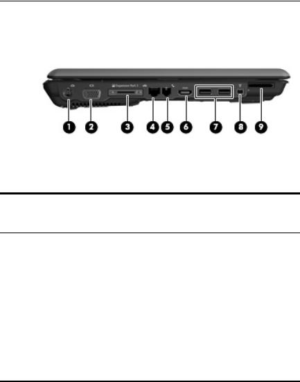
The external components on the left side of the computer are shown below and described in Table 1-2.
Left-Side Components
Table 1-2
Left-Side Components
Item |
Component |
Function |
|
|
|
1 |
S-Video-out jack |
Connects an optional S-Video device such |
|
|
as a television, VCR, camcorder, overhead |
|
|
projector, or video capture card. |
|
|
|
2 |
External monitor port |
Connects an external VGA monitor or |
|
|
projector. |
|
|
|
3 |
Expansion port 3 |
Connects the computer to an optional |
|
|
expansion product. |
The computer has only one expansion port. The term expansion port 3 describes the type of expansion port.
1–8 |
Maintenance and Service Guide |

Product Description
Table 1-2
Left-Side Components (Continued)
Item |
Component |
Function |
|
|
|
4 |
RJ-45 (network) jack |
Connects a network cable. |
|
|
|
5 |
RJ-11 (modem) jack |
Connects a modem cable. |
|
|
|
6 |
HDMI port |
Connects an optional audio or video device, |
|
(select models only) |
such as a high definition television, set-top |
|
|
box, DVD player, or any compatible digital |
|
|
or audio device. |
|
|
|
7 |
USB ports (2) |
Connect optional USB devices. |
|
|
|
8 |
1394 port |
Connects an optional IEEE 1394 or 1394a |
|
(select models only) |
device, such as a camcorder. |
|
|
|
9 |
Memory Reader |
Supports the following optional digital card |
|
(select models only) |
formats: Secure Digital (SD) Memory Card, |
|
|
MultiMediaCard (MMC), Secure Digital |
|
|
Input/Output (SD I/O), Memory Stick (MS), |
|
|
Memory Stick Pro (MSP), xD-Picture Card |
|
|
(XD), xDPicture Card (XD) Type M. |
|
|
|
Maintenance and Service Guide |
1–9 |
Product Description
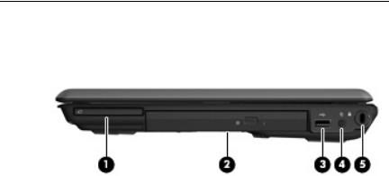
The external components on the right side of the computer are shown below and described in Table 1-3.
Right-Side Components
1–10 |
Maintenance and Service Guide |

Product Description
Table 1-3
Right-Side Components
Item |
Component |
Function |
|
|
|
1 |
ExpressCard slot |
Supports optional ExpressCard/54 cards. |
|
|
|
2 |
Optical drive |
Reads an optical disc. |
|
|
|
3 |
USB port |
Connects an optional USB device. |
|
(select models only) |
|
|
|
|
4 |
Power connector |
Connects an AC adapter. |
|
|
|
5 |
Security cable slot |
Attaches an optional security cable to the |
|
|
computer. |
The security cable is designed to act as a deterrent, but it may not prevent the computer from being mishandled or stolen.
Maintenance and Service Guide |
1–11 |
Product Description
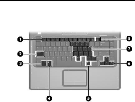
The computer keyboard components are shown below and described in Table 1-4.
Keyboard Components
1–12 |
Maintenance and Service Guide |

Product Description
|
|
Table 1-4 |
|
Keyboard Components |
|
|
|
|
Item |
Component |
Function |
|
|
|
1 |
Function keys |
Execute frequently used system functions |
|
|
when pressed in combination with the |
|
|
fn key. |
|
|
|
2 |
caps lock key |
Enables caps lock and turns on the caps |
|
|
lock light. |
|
|
|
3 |
fn key |
Executes frequently used system |
|
|
functions when pressed in combination |
|
|
with a function key or the esc key. |
|
|
|
4 |
Windows logo key |
Displays the Microsoft Windows Start |
|
|
menu. |
|
|
|
5 |
Windows |
Displays a shortcut menu for items |
|
applications key |
beneath the pointer. |
|
|
|
6 |
Arrow keys |
Move the cursor around the screen. |
|
|
|
7 |
Embedded numeric |
Can be used like the keys on an external |
|
keypad keys |
numeric keypad. |
|
|
|
8 |
num lock key |
Enables numeric lock, turns on the |
|
|
embedded numeric keypad, and turns |
|
|
on the num lock light. |
|
|
|
Maintenance and Service Guide |
1–13 |
Product Description
The computer top components are shown below and described in Table 1-5.
Top Components, Part 1
1–14 |
Maintenance and Service Guide |

Product Description
Table 1-5
Top Components, Part 1
Item |
Component |
Function |
|
|
|
1 |
Internal microphones |
Record sound. |
|
(2, select models only) |
If there is a microphone icon next |
|
|
to each microphone opening, your |
|
|
computer has internal microphones. |
|
|
|
2 |
Power button |
When the computer is |
|
|
■ Off, press to turn on the computer. |
|
|
■ On, press to enter hibernation. |
|
|
■ In standby, briefly press to exit standby. |
|
|
■ In hibernation, briefly press to |
|
|
exit hibernation. |
|
|
If the computer has stopped responding |
|
|
and Microsoft® Windows® shutdown |
|
|
procedures cannot be used, press and hold |
|
|
the power button for at least 5 seconds to |
|
|
turn off the computer. |
|
|
|
3 |
Speakers (2) |
Produce sound. |
|
|
|
Maintenance and Service Guide |
1–15 |
Product Description
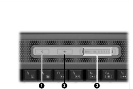
The computer top components are shown below and described in Table 1-6.
Top Components, Part 2
1–16 |
Maintenance and Service Guide |

Product Description
|
|
Table 1-6 |
|
Top Components, Part 2 |
|
|
|
|
Item |
Component |
Function |
|
|
|
1 |
Media button |
If QuickPlay is not installed and the |
|
|
computer is |
|
|
■ On, opens the music program or Media |
|
|
menu, which allows you to select a |
|
|
multimedia program. |
|
|
■ Off, does not function. |
|
|
■ In standby, resumes from standby into |
|
|
Windows. |
|
|
If QuickPlay is installed and the computer is |
|
|
■ On, opens the music program or Media |
|
|
menu, which allows you to select a |
|
|
multimedia program. |
|
|
■ Off, opens the music program or the |
|
|
Media menu, which allows you to select |
|
|
a multimedia program. |
|
|
■ In standby, resumes from standby into |
|
|
Windows. |
|
|
The media button does not affect the |
|
|
procedure for restoring from |
|
|
hibernation. |
|
|
|
2 |
Volume mute button |
Mutes and restores speaker sound. |
|
|
|
3 |
Volume scroll zone |
Adjusts speaker volume. Slide your finger to |
|
|
the left to decrease volume and to the right |
|
|
to increase volume. You can also tap the |
|
|
minus sign on the scroll zone to decrease |
volume, or you can tap the plus sign on the scroll zone to increase volume.
Maintenance and Service Guide |
1–17 |
Product Description
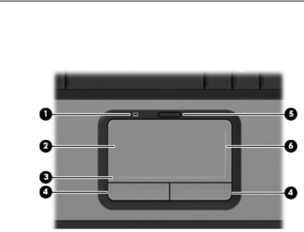
The computer TouchPad components are shown below and described in Table 1-7.
TouchPad Components
1–18 |
Maintenance and Service Guide |

Product Description
|
|
Table 1-7 |
|
Touchpad Components |
|
|
|
|
Item |
Component |
Function |
|
|
|
1 |
TouchPad light |
Blue: TouchPad is enabled. |
|
|
Amber: TouchPad is disabled. |
|
|
|
2 |
TouchPad |
Moves the pointer and selects or activates |
|
|
items on the screen. |
|
|
|
3 |
TouchPad horizontal |
Allows you to scroll left or right. |
|
scroll zone |
|
|
|
|
4 |
Left and right |
Function like the left and right buttons on an |
|
TouchPad buttons |
external mouse. |
|
|
|
5 |
TouchPad on/off |
Enables/disables the TouchPad. |
|
button |
|
|
|
|
6 |
TouchPad vertical |
Allows you to scroll up or down. |
|
scroll zone |
|
|
|
|
Maintenance and Service Guide |
1–19 |

Product Description
The external components on the bottom of the computer are shown below and described in Table 1-8.
Bottom Components
Table 1-8
Bottom Components
Item |
Component |
Function |
|
|
|
1 |
Battery bay |
Holds the battery. |
|
|
|
2 |
Battery release latch |
Releases the battery from the |
|
|
battery bay. |
|
|
|
3 |
Optical drive |
Reads an optical disc. |
|
|
|
1–20 |
Maintenance and Service Guide |

Product Description
Table 1-8
Bottom Components (Continued)
Item |
Component |
Function |
|
|
|
4 |
Memory module |
Contains the memory module slots, the |
|
compartment |
Mini Card WLAN slot, and the |
|
|
RTC battery. |
|
|
|
5 |
Vents (5) |
Enable airflow to cool internal |
|
|
components. |
|
|
The computer fan starts up |
|
|
automatically to cool internal |
|
|
components and prevent |
|
|
overheating. It is normal for the |
|
|
internal fan to cycle on and off |
|
|
during routine operation. |
|
|
|
6 |
Hard drive bay |
Holds the hard drive. |
|
|
|
Maintenance and Service Guide |
1–21 |

Product Description
1.5 Design overview
This section presents a design overview of key parts and features of the computer. Refer to Chapter 3, “Illustrated Parts Catalog,” to identify replacement parts, and Chapter 5, “Removal and Replacement Procedures,” for disassembly steps.
The system board provides the following device connections:
■AMD Turion and Mobile AMD Sempron processors
■Audio
■Display
■ExpressCard
■Fan
■Hard drive
■Intel Core Duo and Celeron processors
■Keyboard and TouchPad
■Memory module
■Mini Card module
ÄCAUTION: To properly ventilate the computer, allow at least a 7.6-cm (3-inch) clearance on the left and right sides of the computer.
The computer uses an electric fan for ventilation. The fan is controlled by a temperature sensor and is designed to turn on automatically when high temperature conditions exist. These conditions are affected by high external temperatures, system power consumption, power management/battery conservation configurations, battery fast charging, and software. Exhaust air is displaced through the ventilation grill located on the left side of the computer.
1–22 |
Maintenance and Service Guide |

2
Troubleshooting
ÅWARNING: Only authorized technicians trained by HP should repair this equipment. All troubleshooting and repair procedures are detailed to allow only subassembly-/module-level repair. Because of the complexity of the individual boards and subassemblies, do not attempt to make repairs at the component level or modifications to any printed wiring board. Improper repairs can create a safety hazard. Any indication of component replacement or printed wiring board modification may void any warranty or exchange allowances.
2.1Setup Utility in Windows XP
The Setup Utility is a ROM-based information and customization utility that can be used even when your Windows operating system is not working or will not load.
The utility reports information about the computer and provides settings for startup, security, and other preferences.
1.Turn on or restart the computer in Windows.
2.Before Windows opens and while the “Press <F10> to enter setup” prompt is displayed in the lower-left corner of the screen, press f10.
Using the Setup Utility
Changing the Language of the Setup Utility
The following procedure explains how to change the language of the Setup Utility. If the computer is not in the Setup Utility, begin at step 1. If the computer is in the Setup Utility, begin at step 2.
Maintenance and Service Guide |
2–1 |
Loading...