


 Loading...
Cisco 3825 Mobile Wireless Edge Router
Software Configuration Guide
August 14, 2008
Americas Headquarters
Cisco Systems, Inc. 170 West Tasman Drive
San Jose, CA 95134-1706 USA http://www.cisco.com Tel: 408 526-4000
800 553-NETS (6387) Fax: 408 527-0883
Text Part Number: OL-15667-03
THE SPECIFICATIONS AND INFORMATION REGARDING THE PRODUCTS IN THIS MANUAL ARE SUBJECT TO CHANGE WITHOUT NOTICE. ALL STATEMENTS, INFORMATION, AND RECOMMENDATIONS IN THIS MANUAL ARE BELIEVED TO BE ACCURATE BUT ARE PRESENTED WITHOUT WARRANTY OF ANY KIND, EXPRESS OR IMPLIED. USERS MUST TAKE FULL RESPONSIBILITY FOR THEIR APPLICATION OF ANY PRODUCTS.
THE SOFTWARE LICENSE AND LIMITED WARRANTY FOR THE ACCOMPANYING PRODUCT ARE SET FORTH IN THE INFORMATION PACKET THAT SHIPPED WITH THE PRODUCT AND ARE INCORPORATED HEREIN BY THIS REFERENCE. IF YOU ARE UNABLE TO LOCATE THE SOFTWARE LICENSE OR LIMITED WARRANTY, CONTACT YOUR CISCO REPRESENTATIVE FOR A COPY.
The following information is for FCC compliance of Class A devices: This equipment has been tested and found to comply with the limits for a Class A digital device, pursuant to part 15 of the FCC rules. These limits are designed to provide reasonable protection against harmful interference when the equipment is operated in a commercial environment. This equipment generates, uses, and can radiate radio-frequency energy and, if not installed and used in accordance with the instruction manual, may cause harmful interference to radio communications. Operation of this equipment in a residential area is likely to cause harmful interference, in which case users will be required to correct the interference at their own expense.
The following information is for FCC compliance of Class B devices: The equipment described in this manual generates and may radiate radio-frequency energy. If it is not installed in accordance with Cisco’s installation instructions, it may cause interference with radio and television reception. This equipment has been tested and found to comply with the limits for a Class B digital device in accordance with the specifications in part 15 of the FCC rules. These specifications are designed to provide reasonable protection against such interference in a residential installation. However, there is no guarantee that interference will not occur in a particular installation.
Modifying the equipment without Cisco’s written authorization may result in the equipment no longer complying with FCC requirements for Class A or Class B digital devices. In that event, your right to use the equipment may be limited by FCC regulations, and you may be required to correct any interference to radio or television communications at your own expense.
You can determine whether your equipment is causing interference by turning it off. If the interference stops, it was probably caused by the Cisco equipment or one of its peripheral devices. If the equipment causes interference to radio or television reception, try to correct the interference by using one or more of the following measures:
•Turn the television or radio antenna until the interference stops.
•Move the equipment to one side or the other of the television or radio.
•Move the equipment farther away from the television or radio.
•Plug the equipment into an outlet that is on a different circuit from the television or radio. (That is, make certain the equipment and the television or radio are on circuits controlled by different circuit breakers or fuses.)
Modifications to this product not authorized by Cisco Systems, Inc. could void the FCC approval and negate your authority to operate the product.
The Cisco implementation of TCP header compression is an adaptation of a program developed by the University of California, Berkeley (UCB) as part of UCB’s public domain version of the UNIX operating system. All rights reserved. Copyright © 1981, Regents of the University of California.
NOTWITHSTANDING ANY OTHER WARRANTY HEREIN, ALL DOCUMENT FILES AND SOFTWARE OF THESE SUPPLIERS ARE PROVIDED “AS IS” WITH ALL FAULTS. CISCO AND THE ABOVE-NAMED SUPPLIERS DISCLAIM ALL WARRANTIES, EXPRESSED OR IMPLIED, INCLUDING, WITHOUT LIMITATION, THOSE OF MERCHANTABILITY, FITNESS FOR A PARTICULAR PURPOSE AND NONINFRINGEMENT OR ARISING FROM A COURSE OF DEALING, USAGE, OR TRADE PRACTICE.
IN NO EVENT SHALL CISCO OR ITS SUPPLIERS BE LIABLE FOR ANY INDIRECT, SPECIAL, CONSEQUENTIAL, OR INCIDENTAL DAMAGES, INCLUDING, WITHOUT LIMITATION, LOST PROFITS OR LOSS OR DAMAGE TO DATA ARISING OUT OF THE USE OR INABILITY TO USE THIS MANUAL, EVEN IF CISCO OR ITS SUPPLIERS HAVE BEEN ADVISED OF THE POSSIBILITY OF SUCH DAMAGES.
CCDE, CCENT, Cisco Eos, Cisco Lumin, Cisco Nexus, Cisco StadiumVision, Cisco TelePresence, the Cisco logo, DCE, and Welcome to the Human Network are trademarks; Changing the Way We Work, Live, Play, and Learn and Cisco Store are service marks; and Access Registrar, Aironet, AsyncOS, Bringing the Meeting To You, Catalyst, CCDA, CCDP, CCIE, CCIP, CCNA, CCNP, CCSP, CCVP, Cisco, the Cisco Certified Internetwork Expert logo, Cisco IOS, Cisco Press, Cisco Systems, Cisco Systems Capital, the Cisco Systems logo, Cisco Unity, Collaboration Without Limitation, EtherFast, EtherSwitch, Event Center, Fast Step, Follow Me Browsing, FormShare, GigaDrive, HomeLink, Internet Quotient, IOS, iPhone, iQ Expertise, the iQ logo, iQ Net Readiness Scorecard, iQuick Study, IronPort, the IronPort logo, LightStream, Linksys, MediaTone, MeetingPlace, MeetingPlace Chime Sound, MGX, Networkers, Networking Academy, Network Registrar, PCNow, PIX, PowerPanels, ProConnect, ScriptShare, SenderBase, SMARTnet, Spectrum Expert, StackWise, The Fastest Way to Increase Your Internet Quotient, TransPath, WebEx, and the WebEx logo are registered trademarks of Cisco Systems, Inc. and/or its affiliates in the United States and certain other countries.
All other trademarks mentioned in this document or Website are the property of their respective owners. The use of the word partner does not imply a partnership relationship between Cisco and any other company. (0807R)
Cisco 3825 Mobile Wireless Edge Router Software Configuration Guide
Copyright © 2005-2008 Cisco Systems, Inc.
All rights reserved.

|
|
|
|
|
C O N T E N T S |
|||||
|
Preface vii |
|
|
|
|
|
|
|
|
|
|
Document Revision History |
vii |
|
|
|
|
|
|
||
|
Objectives |
vii |
|
|
|
|
|
|
|
|
|
Audience viii |
|
|
|
|
|
|
|
|
|
|
Organization |
viii |
|
|
|
|
|
|
|
|
|
Conventions |
viii |
|
|
|
|
|
|
|
|
|
Related Documentation |
ix |
|
|
|
|
|
|
|
|
|
Obtaining Documentation, Obtaining Support, and Security Guidelines x |
|||||||||
|
Overview of the Cisco 3825 Mobile Wireless Edge Router |
|
1-1 |
|
|
|
||||
|
Introduction |
1-1 |
|
|
|
|
|
|
|
|
|
RAN-Optimization Implementation 1-2 |
|
|
|
|
|
|
|||
|
Cisco Abis and Iub Optimization over IP Implementation |
1-2 |
|
|
|
|||||
|
Intelligent Cell Site IP Services 1-5 |
|
|
|
|
|
|
|||
|
Cisco IOS Software Features |
1-6 |
|
|
|
|
|
|
||
|
Software features for the RAN-O Implementation 1-6 |
|
|
|
|
|||||
|
MIB Support |
1-10 |
|
|
|
|
|
|
|
|
|
Limitations and Restrictions |
1-11 |
|
|
|
|
|
|
||
|
RAN-O Implementation Limitations and Restrictions |
1-12 |
|
|
|
|||||
|
UMTS Iub and GSM Abis Implementation Limitations and Restrictions 1-12 |
|||||||||
|
New Features in Cisco IOS Release 12.4(16)MR2 |
1-13 |
|
|
|
|
|
|||
|
Keyword ignore-vpi-vci Added to xconnect Command |
1-13 |
|
|
|
|||||
|
New Features in Cisco IOS Release 12.4(16)MR1 |
1-13 |
|
|
|
|
|
|||
|
Emulation of TDM Circuit via MPLS/IP (PWE3/TDM) |
1-14 |
|
|
|
|||||
|
Transportation of ATM Service via MPLS/IP (PWE3/ATM) |
1-17 |
|
|
|
|||||
|
Transportation of ATM Service via L2TPv3 |
1-20 |
|
|
|
|
|
|||
|
Asymmetric PWE3 |
1-22 |
|
|
|
|
|
|
|
|
|
Ethernet over MPLS |
1-23 |
|
|
|
|
|
|
||
|
PWE3 over MLPPP |
1-24 |
|
|
|
|
|
|
|
|
|
PWE3 Redundancy |
1-24 |
|
|
|
|
|
|
||
|
Maximum Number of Supported ATM Ports |
1-26 |
|
|
|
|
|
|||
|
ATM Cell Switching |
1-26 |
|
|
|
|
|
|
||
|
New Features in Cisco IOS Release 12.4(16)MR |
1-27 |
|
|
|
|
|
|||
|
GSMmux—Global System for Mobile Communication (GSM) Abis Optimization over IP 1-27 |
|||||||||
|
|
|
|
Cisco 3825 Mobile Wireless Edge Router Software Configuration Guide |
|
|
|
|||
|
|
|
|
|
||||||
|
OL-15667-03 |
|
|
|
|
|
|
|
iii |
|
|
|
|
|
|
|
|
|
|
||

Contents
UMTSmux—Universal Mobile Telecommunication System (UMTS) Iub Optimization over IP 1-27
UMTS Congestion Management Control
Inverse Multiplexing over ATM (IMA)
Permanent Virtual Circuit (PVC) Routing
UMTS QoS
|
|
|
Cisco IOS Software Basics |
2-1 |
|
|
|
|
||
|
|
|
Getting Help 2-1 |
|
|
|
|
|
|
|
|
|
|
Understanding Command Modes |
2-2 |
|
|
||||
|
|
|
Undoing a Command or Feature |
2-3 |
|
|
||||
|
|
|
Saving Configuration Changes |
2-3 |
|
|
||||
|
|
|
Where to Go Next |
2-3 |
|
|
|
|
|
|
|
|
|
First-Time Configuration |
3-1 |
|
|
|
|
|
|
|
|
|
Understanding Boot Images |
3-1 |
|
|
|
|||
|
|
|
Understanding the Cisco 3825 Router Interface Numbering 3-1 |
|||||||
|
|
|
Slot and Port Numbering |
|
3-2 |
|
|
|
||
|
|
|
Setup Command Facility |
3-3 |
|
|
|
|
||
|
|
|
Before Starting Your Router |
3-3 |
|
|
||||
|
|
|
Using the Setup Command Facility 3-4 |
|
|
|||||
|
|
|
Configuring Global Parameters |
3-4 |
|
|
||||
|
|
|
Completing the Configuration |
|
3-7 |
|
|
|
||
|
|
|
Configuring the Cisco 3825 Mobile Wireless Edge Router in a RAN-O Solution with the |
|||||||
|
|
|
Command-Line Interface |
4-1 |
|
|
|
|
|
|
|
|
|
Before You Begin |
4-2 |
|
|
|
|
|
|
|
|
|
Verifying the Version of Cisco IOS Software |
4-2 |
|
|||||
|
|
|
Clocking Requirements for Cisco 3825 Router |
4-2 |
|
|||||
|
|
|
Clock-Related Commands |
4-3 |
|
|
||||
|
|
|
Show Controller Command |
4-5 |
|
|
|
|||
|
|
|
Configuration Sequence |
4-6 |
|
|
|
|
||
|
|
|
Configuring the Hostname and Password |
4-6 |
|
|||||
|
|
|
Verifying the Hostname and Password |
4-7 |
|
|||||
|
|
|
Configuring Gigabit Ethernet Interfaces |
4-8 |
|
|||||
|
|
|
Configuring the Backhaul Links |
4-9 |
|
|
||||
|
|
|
Extended Availability Drop and Insert (EADI) 4-20 |
|||||||
|
|
|
Configuring GSM-Abis Links |
4-20 |
|
|
||||
|
|
|
Configuring UMTS Links |
|
4-24 |
|
|
|||
|
|
|
Configuring Redundancy |
|
4-28 |
|
|
|||
|
|
|
Cisco 3825 Mobile Wireless Edge Router Software Configuration Guide |
|
|
|||||
|
|
|
|
|
||||||
|
iv |
|
|
|
|
|
|
|
OL-15667-03 |
|
|
|
|
|
|
|
|
|
|
||

Contents
|
Configuring for SNMP Support |
4-33 |
|
|
|
|
|
|
Configuring Inverse Multiplexing over ATM (IMA) |
4-37 |
|
|
|||
|
Configuring PVC Routing (HSDPA Offload) |
4-41 |
|
|
|
||
|
Configuring UMTS QoS |
4-46 |
|
|
|
|
|
|
Configuring UMTS Congestion Management Control |
4-55 |
|
||||
|
Configuring Satellite Support 4-58 |
|
|
|
|
||
|
Configuring Graceful Degradation |
4-59 |
|
|
|
|
|
|
Saving Configuration Changes |
4-61 |
|
|
|
|
|
|
Example Configurations |
4-61 |
|
|
|
|
|
|
Monitoring and Managing the Cisco 3825 Router 4-69 |
|
|
|
|||
|
Enabling the Cisco 3825 Router for Remote Network Management |
4-69 |
|||||
|
Show Commands for Monitoring the Cisco 3825 Router |
4-71 |
|
||||
|
Where to Go Next 4-73 |
|
|
|
|
|
|
|
Cisco 3825 Mobile Wireless Edge Router RAN-O Command Reference |
|
|||||
A P P E N D I X A |
A-1 |
||||||
|
Configuration Examples B-1 |
|
|
|
|
|
|
A P P E N D I X B |
|
|
|
|
|
|
|
|
Overview B-1 |
|
|
|
|
|
|
|
Asymmetric PWE3 Configuration |
B-2 |
|
|
|
|
|
|
Ethernet over MPLS—VLAN and Port Mode Configuration |
B-15 |
|
||||
|
PWE3 over MLPPP Configuration |
B-21 |
|
|
|
|
|
|
PWE3 Redundancy Configuration |
B-30 |
|
|
|
|
|
|
TDM over MPLS Configuration |
B-36 |
|
|
|
|
|
|
ATM over MPLS Configurations |
B-41 |
|
|
|
|
|
|
ATM over L2TPv3 Configuration |
B-48 |
|
|
|
|
|
|
GSM Only Configuration |
B-55 |
|
|
|
|
|
|
UMTS Only Configuration without IMA |
B-59 |
|
|
|
||
|
Combined GSM and UMTS Configuration |
B-63 |
|
|
|
||
GSM and UMTS with IMA Configuration B-68
GSM and UMTS with IMA and PVC Routing (HSDPA Offload) Configuration B-74
GSM Only Configuration via Satellite
GSM Congestion Management
UMTS Congestion Management
I N D E X
Cisco 3825 Mobile Wireless Edge Router Software Configuration Guide
|
OL-15667-03 |
v |
|

Contents
Cisco 3825 Mobile Wireless Edge Router Software Configuration Guide
|
vi |
OL-15667-03 |
|
|
|

Preface
This preface describes the objectives, audience, organization, and conventions of this software configuration guide.
This preface contains the following sections:
•Document Revision History, page vii
•Objectives, page vii
•Audience, page viii
•Organization, page viii
•Conventions, page viii
•Related Documentation, page ix
•Obtaining Documentation, Obtaining Support, and Security Guidelines, page x
Document Revision History
The Document Revision History table below records technical changes to this document. The table shows the document revision number for the change, the date of the change, and a brief summary of the change. Note that not all Cisco documents use a Document Revision History table.
Revision |
Date |
Change Summary |
|
|
|
OL-15667-03 |
August 14, 2008 |
Provided the following information for Cisco IOS 12.4(19)MR): |
|
|
Described use of the ima group-id command, which the user can |
|
|
employ to configure the IMA Group ID on an IMA interface. |
|
|
|
OL-15667-02 |
April 1, 2008 |
Introduced the following features with Cisco IOS 12.4(16)MR2: |
|
|
Keyword ignore-vpi-vci added to the xconnect command for n:1 |
|
|
VCC cell mode PW |
|
|
|
OL-15667-01 |
March 6, 2008 |
Initial release. |
|
|
|
Objectives
This guide explains how to configure features that enable the Cisco 3825 Mobile Wireless Edge Router to be implemented in an IP Radio Access Network-Optimization (RAN-O) environment.
Cisco 3825 Mobile Wireless Edge Router Software Configuration Guide
|
OL-15667-03 |
vii |
|

Preface
Audience
This publication is designed for the person who will be responsible for configuring the router. This guide is intended for the following audiences:
•Customers with technical networking background and experience
•System administrators who are familiar with the fundamentals of router-based internet working, but who may not be familiar with Cisco IOS software
•System administrators who are responsible for installing and configuring internetworking equipment, and who are familiar with Cisco IOS software
Organization
The major sections of this software configuration guide are listed in the following table:
Chapter |
Title |
Description |
|
|
|
Chapter 1 |
Overview of the |
Describes the purpose of the Cisco 3825 router and its |
|
Cisco 3825 Mobile Wireless |
unique software features. |
|
Edge Router |
|
|
|
|
Chapter 2 |
Cisco IOS Software Basics |
Describes what you need to know about the Cisco IOS |
|
|
software. |
|
|
|
Chapter 3 |
First-Time Configuration |
Describes how to use the setup command facility to |
|
|
configure basic attributes of your router. |
|
|
|
Chapter 4 |
Configuring the |
Describes how to use the Cisco IOS software CLI to |
|
Cisco 3825 Mobile Wireless |
configure basic router functionality in a RAN-O |
|
Edge Router in a RAN-O |
environment. |
|
Solution with the |
|
|
Command-Line Interface |
|
|
|
|
Appendix A |
Cisco 3825 Mobile Wireless |
Provides information about new and changed |
|
Edge Router RAN-O |
commands. |
|
Command Reference |
|
|
|
|
Appendix B |
Configuration Examples |
Provides examples of configurations. |
|
|
|
Conventions
|
|
|
|
This publication uses the following conventions to convey instructions and information. |
|
|
|
||||
Convention |
Description |
||||
|
|
||||
boldface font |
Commands and keywords. |
||||
|
|
||||
italic font |
Variables for which you supply values. |
||||
|
|
|
|
|
|
[ |
] |
|
|
Keywords or arguments that appear within square brackets are optional. |
|
|
|
||||
{x | y | z} |
A choice of required keywords appears in braces separated by vertical bars. You must select one. |
||||
|
|
||||
screen font |
Examples of information displayed on the screen. |
||||
|
|
||||
boldface screen |
Examples of information you must enter. |
||||
font |
|
|
|||
|
|
|
|
|
|
|
|
|
Cisco 3825 Mobile Wireless Edge Router Software Configuration Guide |
||
|
|
|
|||
|
viii |
|
|
OL-15667-03 |
|
|
|
|
|
||

Preface
|
|
|
|
|
|
|
|
Convention |
Description |
|
|
|
|
|
|
< |
> |
Nonprinting characters, for example passwords, appear in angle brackets. |
|
|
|
|
|
[ |
] |
Default responses to system prompts appear in square brackets. |
|
|
|
|
|
Note Means reader take note. Notes contain helpful suggestions or references to material not covered in the manual.
Timesaver Means the described action saves time. You can save time by performing the action described in the paragraph.
Tip Means the following information will help you solve a problem. The tips information might not be troubleshooting or even an action, but could be useful information, similar to a Timesaver.
Caution Means reader be careful. In this situation, you might do something that could result in equipment damage or loss of data.
Related Documentation
The following list includes documentation related to your product by implementation.
Cisco Mobile Wireless RAN Optimization
•Cisco 3825 Mobile Wireless Edge Router Documents
–Cisco 3800 Series Hardware Installation
•Cisco Interface Cards Installation Guides
–Quick Start Guide: Interface Cards
–Cisco Interface Cards Installation Guide
–Cisco 2-port T1/E1-RAN Installation Instructions
•Cisco Network Modules Installation Guides
–Network Modules Quick Start Guide
–Cisco Network Modules Hardware Installation Guide
•Release Notes
–Release Notes for the Cisco 3825 Mobile Wireless Edge Router
Note To obtain the latest information, access the online documentation.
Cisco 3825 Mobile Wireless Edge Router Software Configuration Guide
|
OL-15667-03 |
ix |
|

Preface
Obtaining Documentation, Obtaining Support, and Security
Guidelines
For information on obtaining documentation, obtaining support, providing documentation feedback, security guidelines, and also recommended aliases and general Cisco documents, see the monthly What’s New in Cisco Product Documentation, which also lists all new and revised Cisco technical documentation, at:
http://www.cisco.com/en/US/docs/general/whatsnew/whatsnew.html
Cisco 3825 Mobile Wireless Edge Router Software Configuration Guide
|
x |
OL-15667-03 |
|
|
|
C H A P T E R 1
Overview of the Cisco 3825 Mobile Wireless
Edge Router
The Cisco 3825 Mobile Wireless Edge Router is a networking platform optimized for use in mobile wireless networks; specifically designed to be used at the cell site edge as a part of a 2G, 3G or 4G Radio Access Network (RAN). The Cisco 3825 Mobile Wireless Edge Router is a general purpose router platform specializing in 2/2.5G Global System for Mobile Communication (GSM) and 3G Universal Mobile Telecommunication System (UMTS) RAN backhaul transport and optimization.
The Cisco 3825 router offers high performance at a low cost while meeting the critical requirements for deployment in cell sites, including small size, high availability, and
DC input power flexibility.
This chapter includes the following sections:
•Introduction, page 1-1
•Cisco IOS Software Features, page 1-6
•MIB Support, page 1-10
•Limitations and Restrictions, page 1-11
•New Features in Cisco IOS Release 12.4(16)MR2, page 1-13
•New Features in Cisco IOS Release 12.4(16)MR1, page 1-13
•New Features in Cisco IOS Release 12.4(16)MR, page 1-27
Introduction
A typical RAN is composed of thousands of Base Transceiver Stations (BTSs)/Node Bs, hundreds of Base Station Controllers/Radio Network Controllers (BSCs/RNCs), and several Mobile Switching Centers (MSCs). The BTSs/Node Bs and BSCs/RNCs are often separated by large geographic distances, with the BTSs/Node Bs located in cell sites uniformly distributed throughout a region, and the BSCs, RNCs, and MSCs located at suitably chosen central offices (COs) and/or Mobile Telephone Switching Offices (MTSOs). The traffic generated by a BTS/Node B is transported to the corresponding BSC/RNC across a network, referred to as the backhaul network, which is often a hub-and-spoke topology with hundreds of BTSs/Node Bs connected to a given BSC/RNC by point-to-point time-division multiplexing (TDM) trunks. These TDM trunks may be leased line T1/E1s or their logical equivalents, such as microwave links or satellite channels. The interface between the BTS and BSC in GSM and Code
Cisco 3825 Mobile Wireless Edge Router Software Configuration Guide
|
OL-15667-03 |
1-1 |
|
|
|

Chapter 1 Overview of the Cisco 3825 Mobile Wireless Edge Router
Introduction
Division Multiple Access (CDMA) systems is called the Abis interface. The interface between the Node B and RNC in a UMTS system is called the Iub interface (see Appendix B, “Configuration Examples”, for sample configurations.
RAN-Optimization Implementation
In RAN-Optimization (RAN-O), the Cisco 3825 router extends IP connectivity to the cell site and BTS. The router provides bandwidth-efficient IP transport of GSM and UMTS voice and data bearer traffic, as well as maintenance, control, and signaling traffic, over the leased line backhaul network between the BTS and leased line termination and aggregation node via compression (cRTP/cUDP) and packet multiplexing (Multilink PPP).
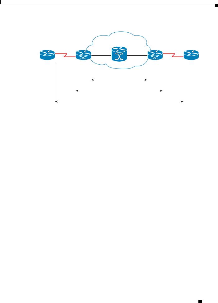
Figure 1-1 shows an example of the placement of and connections for the Cisco 3825 router in RAN-O.
Figure 1-1 Example of Cisco 3825 Router in a RAN-O
Active
T1/E1
Standby
GSM
BTS or |
|
UMTS |
|
Node-B |
Cisco MWR pair |
|
T1/E1 backhaul link to IP RAN aggregation node
203231
The BTS site consists of a pair of Cisco 3825 routers. The pair of routers provides an active router and a standby router for redundancy. A failure of the active router causes the standby router to take over as the active router for the BTS site.
Each pair of Cisco 3825 routers at the BTS site is identical in hardware configuration. The two routers connect to each other through the Gigabit Ethernet (GE) interfaces. The individual backhaul links to a Cisco 3825 router are cabled from a single T1/E1 termination block in the BTS, connecting to both the active and standby routers by means of a Y cable. The redundancy design to control the active/standby transitions of the router pair leverages Hot Standby Router Protocol (HSRP) to control the relays on the Cisco 2-port T1/E1-RAN interface card, Cisco product number VWIC-2T1/E1-RAN (for more information, see Cisco 2-port T1/E1-RAN Installation Instructions) in each router to ensure that the relays on the active router are closed while the relays on the standby router are open, thus avoiding double termination of the T1 (or E1).
Cisco Abis and Iub Optimization over IP Implementation
One solution that mobile wireless operators find of value is Cisco’s ability to optimize RAN backhaul efficiency (see Figure 1-2). For example, Cisco’s GSM Abis Optimization solution increases the T1/E1 bandwidth efficiency by as much as 50%. This means the current traffic loads can be carried using half as many T1/E1 trunks as are presently used. This allows more voice and data calls to be carried over the existing RAN backhaul network, eliminating the need for the operator to add expensive new T1/E1 trunks as traffic demands grow. It will also allow a number of existing trunks to be decommissioned, putting an end to their recurring costs.
Cisco 3825 Mobile Wireless Edge Router Software Configuration Guide
1-2 |
OL-15667-03 |
|
|

Chapter 1 Overview of the Cisco 3825 Mobile Wireless Edge Router
Introduction
Another equally important benefit is that substantial excess capacity is now available in the existing RAN backhaul network. The operator can reallocate this recovered bandwidth to carry traffic from other radios, such as UMTS Node Bs, GPRS, EDGE, 1xEV-DO, PWLANs, and other data overlays. This capability reduces the deployment and operating costs for new technologies, since the operator avoids the up-front and recurring costs of supplementing backhaul capacity. It also accelerates time to revenue from deployments of new radio technologies since there is no need for the operator to wait for additional microwave licenses or leased lines to be supplied.
Compliance with 3GPP2 and 3GPP R5 and R6 transport standards is another appealing aspect of Cisco’s RAN-O solution. Cisco converts today’s CDMA transport networks into 3GPP2-compliant IP RAN transport networks, and GSM and R4/R99 UMTS transport networks into R5/R6 IP RAN transport networks now—and adds multi-radio backhaul compression as well. This means operators can enjoy the benefits of IP transport in their CDMA, GSM, and R4/R99 UMTS RANs today.
Figure 1-2 Example of Cisco 3825 Router in a GSM Abis and UMTS Iub Optimization over IP
GSM BTS |
IP-PBX |
BSC |
TDM
TDM |
|
|
|
|
Cisco |
Cisco |
|
|
ONS 15454 |
||
|
MWR |
||
|
|
|
|
100Base-T |
T1/E1 |
|
IP-PBX |
PWLAN |
|
|
Optimized Abis/lub over IP |
|
|
|
|
|
|
|
|
Cisco |
|
WCDMA-TDD |
|
IP |
|
|
ATM |
|
WiMAX |
|
|
|
Mobile IP/FA |
Mobile |
|
|
|
|
|
|||
(802.16/20) |
ATM |
|
|
IP |
Exchange |
|
|
|
VoIP |
||||
|
|
|
|
|||
|
|
|
|
Content Caching |
|
|
|
|
|
|
Multi VPN |
|
|
|
|
|
|
IP Multicasting |
|
|
|
|
|
|
QoS |
|
|
UMTS Node B |
UMTS Node B |
PPP |
RNC |
|
||
DHCP |
|
|||||
(R4/R99) |
|
(RS/R6) |
|
|
||
|
|
Routing |
|
203232 |
||
HSDPA |
|
|
|
|
||
|
|
|
|
|
||
|
|
|
|
|
|
|
|
Cell Site |
|
|
Access Network |
BSC/RNC Site |
Mobile |
|
|
|
|
|
|
Internet |
|
|
|
|
|
|
Edge |
Cisco GSM Abis Optimization over IP
The Cisco GSM Abis Optimization over IP technology improves T1/E1 bandwidth efficiency by 33% to 50%, corresponding to a GSM voice call capacity gain of 50-100% per T1/E1, depending on the nature of the traffic on the interface.
In a GSM RAN, the interface between the BTS and BSC is a 3GPP reference interface called the Abis interface. The physical trunk connecting a BTS and BSC is typically a T1 or E1 circuit, and carries 24 (T1) or 32 (E1) separate 64 kbps DS0 channels. One or two of these DS0 channels is used to carry control and signaling traffic, while the remainder are used to carry bearer traffic—voice and data from mobile
Cisco 3825 Mobile Wireless Edge Router Software Configuration Guide
|
OL-15667-03 |
1-3 |
|
|
|

Chapter 1 Overview of the Cisco 3825 Mobile Wireless Edge Router
Introduction
users. Each DS0 bearer channel carries up to four sub-multiplexed 16 kbps channels, termed sub-rate DS0s. The voice and data bearer traffic is carried over the sub-rate DS0s in Transcoder and Rate Adaptor Unit (TRAU) frames in accordance with 3GPP TS 08.60 v8.2.1, “In-band control of transcoders and rate adaptors for Enhanced Full Rate (EFR) and full rate traffic channels.” There are several types of TRAU frames: full-rate (FR) or enhanced full-rate (EFR) GSM vocoder frames; Adaptive Multi-Rate (AMR) vocoder frames; silent speech frames; and OAM frames. When a sub-rate DS0 is assigned to a call, TRAU frames are generated in accordance with 3GPP TS 08.60 v8.2.1, “In-band control of transcoders and rate adaptors for EFR and full rate traffic channels.” When a sub-rate DS0 is idle, that is, not assigned to a call, a repeating idle pattern is transmitted in accordance with 3GPP TS 08.54 v8.0.1, “Base Station Controller-Base Transceiver Station (BSC-BTS) interface; Layer 1 structure of physical circuits.”
The transcoder and rate adaptation control function that specifies the TRAU frames provides several opportunities to optimize the Abis interface, and thus optimize the backhaul bandwidth efficiency. For example, when Discontinuous Transmission (DTX) is employed over the air interface, the TRAU frames that are transported on the Abis interface contain standardized redundant bit patterns, known as idle (silent) speech frames (FR and EFR) or “no data” frames (AMR), whenever a voice user is silent (typically 40-60% of the time). As another example, bearer channels that are not assigned to calls each carry known idle bit patterns on the Abis interface as mentioned previously. Thus, even though no radio transmissions are made during silent and idle periods, redundant information is nevertheless transported across the backhaul network thereby unnecessarily consuming precious bandwidth.
Cisco Pseudowire Emulation Edge-to-Edge (PWE3)
PWE3 is a mechanism that emulates the essential attributes of a service, such as ATM or EI/T1 (see Figure 1-3). The required functions of pseudowires (PWs) include encapsulating service-specific Packet Data Units (PDUs) arriving at an ingress port and carrying them across a path or tunnel, managing their timing and order, and any other operations required to emulate the behavior and characteristics of the service as efficiently as possible.
PW is perceived as an unshared link or circuit of the chosen service. However, there may be deficiencies that impede some applications from being carried on a PW. These limitations should be fully described in the appropriate service-specific documents and applicability statements.
Cisco supports standards-based PWE3 as defined by:
•Structure-agnostic TDM over Packet (SAToP), page 1-16
•Structure-aware TDM CESoPSN, page 1-16
•Transportation of ATM Service via MPLS/IP (PWE3/ATM), page 1-17
•Transportation of ATM Service via L2TPv3, page 1-20
A PW is a connection between two provider edge (PE) devices, which connects two attachment circuits (ACs). An AC can be an ATM virtual path identifier/virtual channel identifier (VPI/VCI) or an T1/E1 link.
Cisco 3825 Mobile Wireless Edge Router Software Configuration Guide
1-4 |
OL-15667-03 |
|
|
Chapter 1 Overview of the Cisco 3825 Mobile Wireless Edge Router
Introduction
Figure 1-3 Example of Cisco 3825 Router in a PWE3f
ATM/TDM |
xconnect |
xconnect |
ATM/TDM |
|
|
|
|
MPLS/IP or L2TPv3 |
|
|
|
|
|
|
|
|
|
|
Pseudowire |
|
|
|
|
|
|
|
|
|
|
|
|
|
|
|
|
|
|
|
|
|
Emulated Circuit |
|
|
|
201865 |
||
|
|
|
|
|
|
|
||||
|
|
|
|
|
|
|
|
|
|
|
|
|
|
|
|
|
|
|
|
|
|
Cisco Iub Optimization over IP
The Cisco Iub Optimization over IP technology for R4/R99 (ATM) UMTS RANs improves bandwidth efficiency by as much as 15 to 40%, corresponding to a UMTS voice call capacity gain of 18 to 67%, depending on the type of Iub header and ATM Adaptation Layer traffic sub-cell multiplexing performance. For R5/R6 IP UMTS RANs, Cisco provides compression and low-overhead encryption.
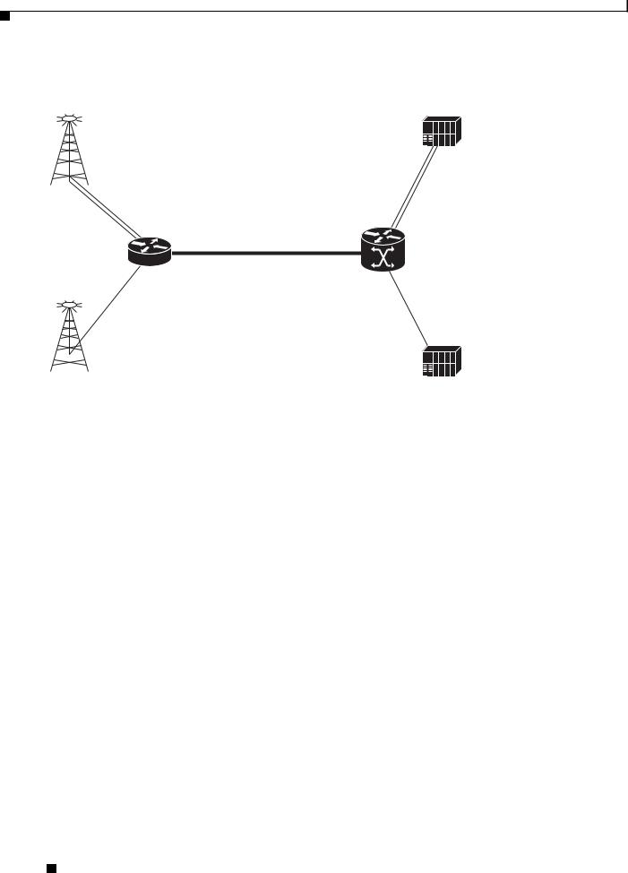
Intelligent Cell Site IP Services
Cisco’s RAN-O solutions also open up the possibility to deliver new profit-enhancing services. This is achieved through the rich set of IP networking features supported in Cisco IOS Software that are now extended to the cell site (see Figure 1-4 on page 1-6).
Cell Site Points-of-Presence (POPs)
Since many cell sites are located in and around downtown areas, hotels, airports, and convention centers, they make attractive sites for co-locating public wireless LAN (PWLAN) access points and other wireless data overlays. Many of these wireless data radios are IP-based. IP networking features, like Mobile IP, VoIP, IP Multicast, Virtual Private Network (VPN), and content caching, enable delivery of new revenue-generating services over these radios. Cisco also provides a wide range of low-latency IP-based quality of service (QoS) and traffic shaping models to allow flexible mixing of multiple traffic types across the same backhaul network. Thus, the cell site becomes a physical point of presence or POP from which to offer hotspot services, or voice and wired Internet service provider (ISP) services to nearby enterprises and residences. The corresponding traffic “rides for free” on the spare backhaul bandwidth made available by Cisco’s Abis and Iub Optimization solutions.
Cisco 3825 Mobile Wireless Edge Router Software Configuration Guide
|
OL-15667-03 |
1-5 |
|
|
|
Chapter 1 Overview of the Cisco 3825 Mobile Wireless Edge Router
Cisco IOS Software Features
Figure 1-4 |
Example of Cisco 3825 Router in a Cell Site POP |
|
GSM/GPRS/ |
|
|
EDGE BTS |
BSC |
|
TDM
TDM
Cisco |
Cisco |
|
ONS 15454 |
||
MWR |
||
T1/E1 |
||
|
||
|
Optimized Abis and lub over IP |
|
ATM |
ATM |
|
|
||
(AAL2/AAL5) |
|
UMTS Node B |
|
RNC |
|
(R4/R99) |
|
|
|
|
|
203233 |
|
|
|
|
|
|
|
|
|
Cell Site |
Access Network |
BSC/RNC Site |
Mobile |
|
|
|
Internet |
|
|
|
Edge |
Cisco IOS Software Features
There is one version of software available for the Cisco 3825 router. This version of the software is required for implementing the Cisco 3825 router in a Radio Access Network-Optimization (RAN-O) configuration.
Software features for the RAN-O Implementation
The software required for implementing the Cisco 3825 router consists the Cisco IOS software running on the MIPs-based portion of the Cisco 3825 router hardware.
Cisco IOS software functions added to the Cisco 3825 router for the RAN-O implementation include:
•Redundancy logic—For monitoring Hot Standby Router Protocol (HSRP) information to determine the active and standby router and control T1 termination.
•Failover logic—To force a switchover for hardware failures or an over-temperature condition.
•Relay control—To open and close the T1/E1 interfaces on the active and standby routers.
•Diagnostic functions—To monitor the “health” of the standby Cisco 3825 router.
Cisco 3825 Mobile Wireless Edge Router Software Configuration Guide
1-6 |
OL-15667-03 |
|
|

Chapter 1 Overview of the Cisco 3825 Mobile Wireless Edge Router
Cisco IOS Software Features
Software Features
Standard Cisco IOS software features supported in the Cisco 3825 router for the RAN-O implementation include:
Simple Services
•DHCP
•PPP
•NAT
•OSPF
•RIP
Intelligent Services
•QoS
•VPN
•IP Multicast
•Mobile IP/FA
•content caching
•MPLS
•L2TPv3
Other Services
•ACFC and PFC Handling During PPP Negotiation
•HSRP
•NTP
•SNMP
Redundancy Support
In a RAN-O application, to ensure availability, the backhaul links to a Cisco 3825 router are redundantly cabled to the Cisco 2-port T1/E1-RAN card. This card, designed specifically for the
Cisco MWR 1941-DC-A router and Cisco 3825 router includes relays that activate the T1/E1 ports. These relays allow “Y” cabling for router redundancy where the T1/E1 link is not redundant and default to open. The relays are controlled by HSRP/redundancy protocol between the two routers connected to the same T1/E1.
Note If you choose to use the Cisco 3825 router in a non-redundant configuration, you must close the relays on the card using the standalone subcommand. Also, redundancy parameters are processed when the router is booted up. These parameters cannot be changed “on the fly.”
HSRP
Cisco’s HSRP is used to control which router is active and which is standby. HSRP uses a priority scheme to determine which HSRP-configured router is to be the default active router. Priority is determined first by the configured priority value, then by the IP address. In each case, a higher value is of greater priority.
Cisco 3825 Mobile Wireless Edge Router Software Configuration Guide
|
OL-15667-03 |
1-7 |
|
|
|

Chapter 1 Overview of the Cisco 3825 Mobile Wireless Edge Router
Cisco IOS Software Features
Configuration Statements for CISCO-IP-RAN-BACKHAUL-MIB
This section contains detailed information on how to enable notifications provided by the
CISCO-IP-RAN-BACKHAUL-MIB.
With Cisco IOS Release 12.4(16)MR1, the Cisco 3825 router supports the following MIB:
CISCO-IP-RAN-BACKHAUL-MIB
This MIB is compatible with Cisco Mobile Wireless Transport Manager (MWTM) 5.0 or later. It provides information on the optimization on the optimization of the following traffic types:
•GSM—providing information between a BTS and the corresponding BSC
•UMTS—providing information on optimization between a Node Band the corresponding RNC. NOTIFICATIONS
ciscoIpRanBackHaulGsmAlarm
Provides information alarms associated with Global System for Mobile Communications (GSM)-Abis interfaces. Only enables GSM Abis. See Appendix A, “Cisco 3825 Mobile Wireless Edge Router RAN-O Command Reference” for more information.
conf t
snmp-server enable traps ipran alarm-gsm
ciscoIpRanBackHaulUmtsAlarm
Provides information alarms associated with Universal Mobile Telecommunications System (UMTS)-Iub interfaces. Only enables UMTS Iub. See Appendix A, “Cisco 3825 Mobile Wireless Edge Router RAN-O Command Reference” for more information.
conf t
snmp-server enable traps ipran alarm-umts
ciscoIpRanBackHaulRcvdUtil + ciscoIpRanBackHaulSentUtil
Provides information on backhaul utilization. Only enables backhaul utilization. See Appendix A, “Cisco 3825 Mobile Wireless Edge Router RAN-O Command Reference” for more information.
conf t
snmp-server enable traps ipran util
Note The snmp-server enable traps ipran util command is obsolete. CLI accepts the command to maintain compatibility.
To specify all notifications, specify the component name. See Appendix A, “Cisco 3825 Mobile Wireless Edge Router RAN-O Command Reference” for more information.
conf t
snmp-server enable traps ipran
The following configuration statements are used to provide additional information about device and control generation of notifications:
|
|
|
ipran-mib ? |
|
|
|
|
|
backhaul-notify-interval |
Interval for backhaul utilization (Obsolete. |
|
|
|
|
|
Provided only to maintain compatibility.) |
|
|
|
|
location |
Location of device |
|
|
|
|
snmp-access |
Specify type snmp connectivity |
|
|
|
|
Cisco 3825 Mobile Wireless Edge Router Software Configuration Guide |
|
|
|
|
|
|
|
|
|
1-8 |
|
|
OL-15667-03 |
|
|
|
|
|
||

Chapter 1 Overview of the Cisco 3825 Mobile Wireless Edge Router
Cisco IOS Software Features
ipran-mib ? |
|
threshold-acceptable |
Acceptable utilization threshold (Obsolete. |
|
Provided only to maintain compatibility.) |
threshold-overloaded |
Overloaded utilization threshold (Obsolete. |
|
Provided only to maintain compatibility.) |
threshold-warning |
Warning utilization threshold (Obsolete. Provided |
|
only to maintain compatibility.) |
ipran-mib backhaul-notify-interval |
|
For more information on these commands, see Appendix A, “Cisco 3825 Mobile Wireless Edge Router RAN-O Command Reference”.
Cisco 3825 Mobile Wireless Edge Router Software Configuration Guide
|
OL-15667-03 |
1-9 |
|
|
|

Chapter 1 Overview of the Cisco 3825 Mobile Wireless Edge Router
MIB Support
MIB Support
The Cisco 3825 router supports the following MIBs:
• |
ADSL-DMT-LINE-MIB |
• CISCO-IETF-ATM2-PVCTRAP-MIB-EXTN |
|
• |
ADSL-LINE MIB |
• |
CISCO-IETF-ATM2-PVCTRAP-MIB |
• |
ATM-MIB |
• |
CISCO-IETF-NAT-MIB |
• |
BRIDGE-MIB |
• |
CISCO-IETF-PW-MIB |
• CISCO-AAA-SERVER-MIB |
• |
CISCO-IETF-PW-MPLS-MIB |
|
• |
CISCO-AAL5-MIB |
• |
CISCO-IETF-PW-TC-MIB |
• CISCO-ACCESS-ENVMON-MIB |
• |
CISCO-IF-EXTENSION-MIB |
|
• |
CISCO-ATM-EXT-MIB |
• CISCO-IMAGE-MIB |
|
• CISCO-ATM-PVCTRAP-EXTN-MIB |
• CISCO-IP-RAN-BACKHAUL-MIB |
||
• |
CISCO-BULK-FILE-MIB |
• CISCO-IPMROUTE-MIB |
|
• |
CISCO-CALL-APPLICATION-MIB |
• CISCO-MEMORY-POOL-MIB |
|
• |
CISCO-CALL-HISTORY-MIB |
• CISCO-MVPN-MIB |
|
• |
CISCO-CAR-MIB |
• CISCO-NBAR-PROTOCOL-DISCOVERY-MIB |
|
• |
CISCO-CAS-IF-MIB |
• CISCO-NETFLOW-MIB |
|
• CISCO-CCME-MIB |
• |
CISCO-NTP-MIB |
|
• |
CISCO-CDP-MIB |
• |
CISCO-PIM-MIB |
• |
CISCO-CIRECUIT-INTERFACE-MIB |
• |
CISCO-PING-MIB |
• |
CISCO-CLASS-BASED-QOS-MIB |
• CISCO-POP-MGMT-MIB |
|
• CISCO-CONFIG-MAN-MIB |
• |
CISCO-PPPOE-MIB |
|
• CISCO-DIAL-CONTROL-MIB |
• CISCO-PROCESS-MIB |
||
• |
CISCO-DSL-CPE-MIB |
• CISCO-QUEUE-MIB |
|
• |
CISCO-ENTITY-ASSET-MIB |
• CISCO-RTTMON-MIB |
|
• |
CISCO-ENTITY-EXT-MIB |
• CISCO-SAA-APM-MIB |
|
• CISCO-ENTITY-VENDORTYPE-OLD-MIB |
• |
CISCO-SMI |
|
• CISCO-ENVMON-MIB |
• CISCO-SNAPSHOT-MIB |
||
• |
CISCO-FLASH-MIB |
• CISCO-SNMP--TARGET-EXT-MIB |
|
• CISCO-FRAME-RELAY-MIB |
• |
CISCO-SRST-MIB |
|
• |
CISCO-FTP-CLIENT-MIB |
• CISCO-STACKMAKER-MIB |
|
• |
CISCO-HSRP-MIB |
• CISCO-SYSLOG-MIB |
|
• |
CISCO-ICSUDSU-MIB |
• |
CISCO-TC |
|
|
|
|
|
Cisco 3825 Mobile Wireless Edge Router Software Configuration Guide |
1-10 |
OL-15667-03 |
Chapter 1 Overview of the Cisco 3825 Mobile Wireless Edge Router
Limitations and Restrictions
•CISCO-TCP-MIB
•CISCO-VLAN-IFTABLE-RELATIONSHIP- MIB
•CISCO-VLAN-MEMBERSHIP-MIB
•CISCO-VOICE-ANALOG-IF-MIB
•CISCO-VOICE-ATM-DIAL-CONTROL-MIB
•CISCO-VOICE-COMMON-DIAL-CONTROL- MIB
•CISCO-VOICE-DIAL-CONTROL-MIB
•CISCO-VOICE-DNIS-MIB
•CISCO-VOICE-ENABLED-LINK-MIB
•CISCO-VOICE-FR-DIAL-CONTROL-MIB
•CISCO-VOICE-IF-MIB
•CISCO-VOICE-NUMBER-EXPANSION-MIB
•CISCO-VOICE-URI-CLASS-MIB
•CISCO-VPDN-MGMT-EXT-MIB
•CISCO-VPDN-MGMT-MIB
•CISCO-VTP-MIB
•DIAL-CONTROL-MIB
•DS1-MIB
•DS3-MIB
•ETHERLIKE-MIB
•EVENT-MIB
•EXPRESSION-MIB
•IF-MIB
•IGMP-MIB
•IMA-MIB
•INT-SERV-GUARANTEED-MIB
•INT-SERV-MIB
•IP-FORWARD-MIB
•ISDN-MIB
•MSDP-MIB
•OLD-CISCO-CHASSIS-MIB
•OLD-CISCO-FLASH-MIB
•OLD-CISCO-INTERFACES-MIB
•OLD-CISCO-IP-MIB
•OLD-CISCO-SYS-MIB
•OLD-CISCO-TCP-MIB
•OLD-CISCO-TS-MIB
•OSPF-MIB
•OSPF-TRAP-MIB
•PIM-MIB
•RFC1213-MIB
•RFC1231-MIB
•RFC1315-MIB
•RFC1406-MIB
•RMON-MIB
•RS-232-MIB
•RSVP-MIB
•SMON-MIB
•SNMP-TARGET-MIB
•SONET-MIB
•TCP-MIB
•UDP-MIB
•VRRP-MIB
•XGCP-MIB
Limitations and Restrictions
The following restrictions applies when using the Cisco 2-port T1/E1-RAN interface card in the Cisco 3825 router:
Caution The Cisco 3825 router does not support online insertion and removal (OIR) of the
Cisco 2-port T1/E1-RAN interface card. Any attempt to perform OIR on a card in a powered up router might cause damage to the card.
|
|
Cisco 3825 Mobile Wireless Edge Router Software Configuration Guide |
|
|
|
|
|
|
|||
|
OL-15667-03 |
|
|
1-11 |
|
|
|
|
|
||

Chapter 1 Overview of the Cisco 3825 Mobile Wireless Edge Router
Limitations and Restrictions
Caution The Cisco 3825 router does not support OIR of network modules. Any attempt to perform OIR on a card in a powered up router might cause damage to the card.
Note The Cisco NM-2W network interface module only is only supported on the Cisco 3825 router on shorthaul with or without Inverse Multiplexing over ATM (IMA). It is not supported on the Cisco 3825 router on shorthaul with GSM.
RAN-O Implementation Limitations and Restrictions
The following list of restrictions applies when implementing the Cisco 3825 router in a Radio Access Network-Optimization (RAN-O) configuration.
Hardware not Supported on the Cisco 3825 Router
Use of additional voice/WAN interface card (VWIC) cards. The only supported VWIC is the Cisco 2-port T1/E1-RAN.
UMTS Iub and GSM Abis Implementation Limitations and Restrictions
The following list of restrictions applies when implementing the UMTS Iub or GSM Abis application in a RAN-O configuration.
Hardware not Supported for UMTS Iub
The Cisco MWR 1941-DC router does not support UMTS Iub as it does not include the Advanced Integration Module (AIM) slot connector on the motherboard. Only the Cisco MWR 1941-DC-A router and Cisco 3825 router are supported for UMTS Iub.
Hardware not Supported for GSM Abis
The Network Interface Module (NM-2W) does not support GSM Abis as the HDLC Controller channel does not interface with the NM-2W. GSM Abis is only supported through the Cisco 2-port T1/E1-RAN card through the four voice/WAN interface card (VWIC) ports on the Cisco 3825 router (see Figure 1-5 on page 1-13).
|
Cisco 3825 Mobile Wireless Edge Router Software Configuration Guide |
1-12 |
OL-15667-03 |

Chapter 1 Overview of the Cisco 3825 Mobile Wireless Edge Router
New Features in Cisco IOS Release 12.4(16)MR2
Figure 1-5 Example of Cisco 3825 Router VWIC and NM-2W Configuration Options Block Diagram
GSM |
|
UMTS |
|
IP |
• VWIC-2T1/E1-RAN |
|
• VWIC-2T1/E1-RAN |
|
• VWIC-2T1/E1-RAN |
used for T1/E1 |
|
used for T1/E1 |
|
used for T1/E1 |
• *MUST* reside in one |
|
• VWIC FPGA unused |
|
• VWIC FPGA unused |
of four WIC slots to |
|
for UMTS |
|
for IP |
traverse HDLC Ctrl |
|
• Direct routing to |
|
• Direct routing to |
(8 GSM E1 max) |
|
AIM-ATM |
|
IOS CPU |
|
|
|
|
|
|
AIM-ATM-8 |
|
|
|
|
IOS CPU |
|
|
|
|
Module on |
|
|
|
|
|
|
||
|
Motherboard |
|
|
|
|
|
|
|
|
|
NM - 2W |
|
NM - 2W |
|
|
|
|
HDLC Ctrl |
|
|
|
|
|
|
|
|
|
||
RAN WIC RAN WIC |
RAN WIC RAN WIC |
RAN WIC |
RAN WIC |
RAN WIC |
RAN WIC |
280206 |
|||
|
|
|
|
|
|
|
|
|
|
UMTS |
IP |
UMTS |
IP |
UMTS |
UMTS |
IP |
GSM |
|
|
lub |
|
lub |
|
lub |
|
lub |
|
Abis |
|
New Features in Cisco IOS Release 12.4(16)MR2
With Cisco IOS Release 12.4(16)MR2, the Cisco MWR 1941-DC-A router supports the following feature:
• Keyword ignore-vpi-vci Added to xconnect Command, page 1-13
Keyword ignore-vpi-vci Added to xconnect Command
With the ignore-vpi-vci keyword configured, the MWR ignores the VPI/VCI value in the PW packet and does a blind rewrite with the local configured AC-side PVC's VPI/VCI value. This applies only when the xconnect command is configured under the PVC, which is the N:1 with N=1 special case. It does not apply when the xconnect command is configured under the subinterface, which supports N>1.
The xconnect command with keyword ignore-vpi-vci results in the PVC mapping being done in a cooperative way if the MWR works the same way as the receiving router. Without this command, the MWR checks the VPI/VCI value inside PW packet for matches against the local configured PVC or PVC-mapping. With the ignore-vpi-vci keyword configured, the MWR ignores the VPI/VCI header inside the received PW packet and does a blind rewrite with the local configured AC-side PVC's VPI/VCI value.
New Features in Cisco IOS Release 12.4(16)MR1
With Cisco IOS Release 12.4(16)MR1, the Cisco 3825 router supports the following:
Cisco 3825 Mobile Wireless Edge Router Software Configuration Guide
|
OL-15667-03 |
1-13 |
|
|
|

Chapter 1 Overview of the Cisco 3825 Mobile Wireless Edge Router
New Features in Cisco IOS Release 12.4(16)MR1
•Emulation of TDM Circuit via MPLS/IP (PWE3/TDM), page 1-14
–Structure-agnostic TDM over Packet (SAToP), page 1-16
–Structure-aware TDM CESoPSN, page 1-16
•Transportation of ATM Service via MPLS/IP (PWE3/ATM), page 1-17
–Transparent Cell Transport Service/ATM Port Mode, page 1-17
–ATM N-to-One VCC Cell Mode, page 1-17
–ATM AAL5 CPCS-SDU Mode, page 1-18
–ATM One-to-One VCC Cell Mode, page 1-18
•Transportation of ATM Service via L2TPv3, page 1-20
–ATM Port Cell Relay Service, page 1-20
–ATM VCC Cell Relay Service, page 1-20
–ATM AAL5-SDU Mode, page 1-21
•Asymmetric PWE3, page 1-22
•Ethernet over MPLS, page 1-23
–VLAN Mode, page 1-23
–Port Mode, page 1-23
•PWE3 over MLPPP, page 1-24
•PWE3 Redundancy, page 1-24
–TDM PWE3 Redundancy, page 1-25
–ATM PWE3 Redundancy, page 1-25
–Ethernet PWE3 Redundancy, page 1-25
•Maximum Number of Supported ATM Ports, page 1-26
•ATM Cell Switching, page 1-26
Emulation of TDM Circuit via MPLS/IP (PWE3/TDM)
PWE3 is a mechanism that emulates the essential attributes of a T1/E1 line over a packet-switched network (PSN). This evolutionary technology allows you to migrate all packet networks from legacy TDM networks, yet provides transport for legacy applications. PWE3/TDM emulates T1/E1 unstructured and structured lines, including NxDS0 circuits over a Multiprotocol Label Switching (MPLS) infrastructure.
Configuration for provisioning and creating the PW is done through the existing xconnect interface.
A new command cem-group has been added to this feature to create a circuit emulation (CEM) channel from one or more time slots of T1/E1.
The group-number keyword identifies the group number used for this channel.
•For T1 controller, the range is 0-23. (24 cem-groups id)
•For E1 controller, the range is 0-30. (30 cem-groups id)
Use the unframed keyword to specify that a single CEM channel is being created, including all time slots with no framing structure defined. If time slots are defined, the PWE3 circuit is circuit emulation service over packet-switched network (CESoPSN).
|
Cisco 3825 Mobile Wireless Edge Router Software Configuration Guide |
1-14 |
OL-15667-03 |

Chapter 1 Overview of the Cisco 3825 Mobile Wireless Edge Router
New Features in Cisco IOS Release 12.4(16)MR1
Use the time slots keyword and the timeslot-range argument to specify the time slots to be included in the CEM channel. The list of time slots may include commas and hyphens with no spaces between the numbers, commas, and hyphens.
The following example illustrates the use of the cem-group command:
SATOP
controller el 0/0/0 cem-group 0 unframed
int cem 0/0/0 cem 0
xconnect 10.10.10.10 200 encap mpls
CESoPSN
controller e1 0/0/1 cem-group 0 timeslots 1-31
int cem 0/0/1 cem 0
xconnect 10.10.10.10 200 encap mpls
A new command sample-rate has been added to this feature to specify in milliseconds the rate that hardware samples data on the attached circuit.
The default is 1 ms. The sample-rate command translates into the payload-size that is sent over the circuit.
•32-time slots at 1 ms = 256-bytes (32-time slots * 8-bytes/timeslot/ms)
•24-time slots at 2 ms = 384-bytes (24-time slots * 16-bytes/timeslot/ms)
•10-time slots at 1 ms = 80-bytes (10-time slots * 8-bytes/timeslot/ms) The following example illustrates the use of the sample-rate command:
interface CEM0/0/0 no ip address
cem 0 sample-rate 2
xconnect 10.10.10.10 200 encapsulation mpls
A new command dejitter-buffer has been added to this feature to specify the size of the dejitter-buffer used to compensate for the network jitter.
•Use the size argument to specify the size of the buffer in milliseconds.
•Size can vary from 4 - 500 ms; default is 4 ms.
The following example illustrates the use of the dejitter-buffer command:
interface CEM0/0/0 no ip address
cem 0 dejitter-buffer 10
xconnect 10.10.10.10 200 encapsulation mpls
A new command idle-pattern has been added to this feature to specify the data pattern transmitted on the T1/E1 when missing packets are detected on the PWE3 circuit.
The default idle-pattern command is 0xFF.
|
|
Cisco 3825 Mobile Wireless Edge Router Software Configuration Guide |
|
|
|
|
|
|
|||
|
OL-15667-03 |
|
|
1-15 |
|
|
|
|
|
||

Chapter 1 Overview of the Cisco 3825 Mobile Wireless Edge Router
New Features in Cisco IOS Release 12.4(16)MR1
The following example illustrates the use of the idle-pattern command:
interface CEM0/0/0 no ip address
cem 0 idle-pattern 0x55
xconnect 10.10.10.10 200 encapsulation mpls
A new command shutdown has been added to this feature to administratively shut down the CEM channel.
Default: cem channel is created in a “no shut” state.
The following example illustrates the use of the shutdown command:
interface CEM0/0/0
no ip address cem 0
shutdown
xconnect 10.10.10.10 200 encapsulation mpls
A new command class cem has been added to this feature to allow CEM interface parameters to be configured in a class and applied to CEM interfaces together. This command works in the same manner for CEM interfaces as the pseudowire-class command does for xconnect.
The following example illustrates the use of the class cem command:
class cem mycemclass dejitter-buffer 10 sample-rate 2
interface CEM0/0/0 no ip address
cem 0
xconnect 10.10.10.10 200 encapsulation mpls cem class mycemclass
Structure-agnostic TDM over Packet (SAToP)
SAToP encapsulates TDM bit-streams (T1, E1, T3, E3) as PWs over PSNs. It disregards any structure that may be imposed on streams, in particular the structure imposed by the standard TDM framing.
The protocol used for emulation of these services does not depend on the method in which attachment circuits are delivered to the PEs. For example, a T1 attachment circuit is treated in the same way regardless of whether it is delivered to the PE on copper, multiplexed in a T3 circuit, mapped into a virtual tributary of a SONET/SDH circuit, or carried over an ATM network using unstructured ATM circuit emulation service (CES) [ATM-CES]. Termination of any specific “carrier layers” used between the PE and CEM is performed by an appropriate network service provider (NSP).
Structure-aware TDM CESoPSN
CESoPSN encapsulates structured (NxDS0) TDM signals as PWs over PSNs. It complements similar work for structure-agnostic emulation of TDM bit-streams, such as PWE3-SAToP.
Emulation of NxDS0 circuits saves PSN bandwidth and supports DS0-level grooming and distributed cross-connect applications. It also enhances resilience of CE devices to the effects of loss of packets in the PSN.
|
Cisco 3825 Mobile Wireless Edge Router Software Configuration Guide |
1-16 |
OL-15667-03 |

Chapter 1 Overview of the Cisco 3825 Mobile Wireless Edge Router
New Features in Cisco IOS Release 12.4(16)MR1
Transportation of ATM Service via MPLS/IP (PWE3/ATM)
An ATM PW is used to carry ATM cells over an MPLS network. It is an evolutionary technology that allows you to migrate all packet networks from legacy ATM networks, yet provides transport for legacy applications.
Configuration for provisioning and creating the PW is done through the existing xconnect command.
The following PW modes are supported in this release:
•Transparent Cell Transport Service/ATM Port Mode, page 1-17
•ATM N-to-One VCC Cell Mode, page 1-17
•ATM AAL5 CPCS-SDU Mode, page 1-18
•ATM VCC Cell Relay Service, page 1-20
The following examples illustrates how different modes of PWs are configured.
Transparent Cell Transport Service/ATM Port Mode
ATM port mode maps the entire ATM interface to a PW. Use the xconnnect command under the interface mode to configure a port mode PW.
A sample configuration is written as follows:
interface ATM0/0/0 no ip address scrambling-payload
atm mcpt-timers 1000 2000 3000 no atm ilmi-keepalive
atm cell-packing 28 mcpt-timer 3
xconnect 99.99.99.99 100 encapsulation mpls sequencing both pvc 1/35 l2transport
encapsulation aal0
!
pvc 1/36 l2transport encapsulation aal0
!
pvc 1/37 l2transport encapsulation aal0
!
ATM N-to-One VCC Cell Mode
ATM N:1 VCC cell relay mode maps one or more permanent virtual circuits (PVCs) to one PW. There are two ways to configure N:1 VCC in cell relay mode:
1.When only one PVC needs to be mapped to a PW, configure the xconnect command under the PVC mode to configure a N:1 VCC cell relay mode PW.
A sample configuration is written as follows:
interface ATM0/0/1 no ip address load-interval 30 scrambling-payload
atm mcpt-timers 1000 2000 3000 no atm ilmi-keepalive
pvc 0/101 l2transport encapsulation aal0 cell-packing 28 mcpt-timer 3
|
|
Cisco 3825 Mobile Wireless Edge Router Software Configuration Guide |
|
|
|
|
|
|
|||
|
OL-15667-03 |
|
|
1-17 |
|
|
|
|
|
||

Chapter 1 Overview of the Cisco 3825 Mobile Wireless Edge Router
New Features in Cisco IOS Release 12.4(16)MR1
xconnect 99.99.99.99 1101 encapsulation mpls sequencing both
!
2.When more than one PVC needs to be mapped to a PW, configure the xconnect command under the subinterface mode to configure N:1 VCC cell in relay mode PW. All PVCs configured under this subinterface are mapped to the PW.
A sample configuration is written as follows:
interface ATM0/0/1.1 multipoint no snmp trap link-status
atm cell-packing 28 mcpt-timer 3
xconnect 99.99.99.99 1200 encapsulation mpls sequencing both pvc 1/35 l2transport
encapsulation aal0
!
pvc 1/36 l2transport encapsulation aal0
!
pvc 1/37 l2transport encapsulation aal0
ATM AAL5 CPCS-SDU Mode
ATM adaptation layer 5 (AAL5) SDU mode maps one AAL5 type PVC to a PW. Use the xconnect command under an AAL5 encapsulation type PVC to configure AAL5 SDU mode PW.
A sample configuration is written as follows:
interface ATM0/0/1 no ip address load-interval 30 scrambling-payload
no atm ilmi-keepalive pvc 0/100 l2transport encapsulation aal5
xconnect 99.99.99.99 1100 encapsulation mpls sequencing both
!
ATM One-to-One VCC Cell Mode
ATM 1:1 VCC cell relay mode maps one PVC to a PW. Use a one-to-one keyword in the xconnect command mode to specify a 1:1 VCC relay mode PW.
A sample configuration is written as follows:
interface ATM0/0/1 no ip address load-interval 30 scrambling-payload
atm mcpt-timers 1000 2000 3000 no atm ilmi-keepalive
pvc 0/102 l2transport encapsulation aal0 cell-packing 28 mcpt-timer 3
xconnect 99.99.99.99 1102 encapsulation mpls sequencing both one-to-one
!
|
Cisco 3825 Mobile Wireless Edge Router Software Configuration Guide |
1-18 |
OL-15667-03 |

Chapter 1 Overview of the Cisco 3825 Mobile Wireless Edge Router
New Features in Cisco IOS Release 12.4(16)MR1
Cell Packing
Cell packing or concatenation supports Port, N:1 VCC cell, or 1:1 VCC cell mode. Cell packing can be configured with a parameter of a maximum number of cells and a parameter of cell packing timer.
“atm mcpt-timers [timer1] [timer2] [timer3]” can be used under the interface mode to configure three cell packing timer values. Timer values are in microseconds, and the granularity is 1,000 microseconds, namely 1 millisecond. The timer value is referenced by the “atm cell-packing …” and “cell-packing …” commands.
The sample below configures cell packing for ATM port modes. It specifies a maximum number of cells as 28 and a cell packing timer as 3,000 microseconds.
interface ATM0/0/0 no ip address scrambling-payload
atm mcpt-timers 1000 2000 3000 no atm ilmi-keepalive
atm cell-packing 28 mcpt-timer 3
xconnect 99.99.99.99 100 encapsulation mpls sequencing both pvc 1/35 l2transport
encapsulation aal0
!
pvc 1/36 l2transport encapsulation aal0
!
pvc 1/37 l2transport encapsulation aal0
!
The sample below configures cell packing for the N:1 VCC cell relay mode PW. It specifies a maximum number of cells as 20 and a cell packing timer as 4,000 microseconds.
interface ATM0/0/1 no ip address load-interval 30 scrambling-payload
atm mcpt-timers 2000 3000 4000 no atm ilmi-keepalive
pvc 0/101 l2transport encapsulation aal0 cell-packing 20 mcpt-timer 3
xconnect 99.99.99.99 1101 encapsulation mpls sequencing both
PVC Mapping
The pw-pvc command configures PVC mapping or rewrites for PW-configured PVCs. It specifies the PW-side vpi/vci value used in sending and receiving PW packets for specified PVCs.
The following example illustrates the use of the pw-pvc command:
pvc 0/40 l2transport
encapsulation aal0 pw-pvc 1/40
xconnect 1.1.1.1 40 encapsulation mpls
|
|
Cisco 3825 Mobile Wireless Edge Router Software Configuration Guide |
|
|
|
|
|
|
|||
|
OL-15667-03 |
|
|
1-19 |
|
|
|
|
|
||

Chapter 1 Overview of the Cisco 3825 Mobile Wireless Edge Router
New Features in Cisco IOS Release 12.4(16)MR1
Transportation of ATM Service via L2TPv3
This service transports ATM services over IP networks. It allows you to migrate all PSNs from ATM legacy networks while still providing ATM legacy services.
The following PW modes are supported in this release:
•ATM Port Cell Relay Service, page 1-20
•ATM VCC Cell Relay Service, page 1-20
•ATM AAL5-SDU Mode, page 1-21
Configuring Layer 2 Tunnel Protocol version 3 (L2TPv3)-based PWs is very similar to configuring MPLS-based PWs, except that a pseudowire-class command is required to be configured for L2TPv3-based PWs.
A sample configuration of the L2TPv3 pseudowire-class command is written as follows:
pseudowire-class l2tp encapsulation l2tpv3 sequencing both
ip local interface Loopback0
ATM Port Cell Relay Service
ATM port mode maps the entire ATM interface to a PW. Use the xconnnect command under the interface mode to configure a port mode PW. The ATM interface maps to the PW.
A sample configuration is written as follows:
interface ATM0/0/0 no ip address scrambling-payload
atm mcpt-timers 1000 2000 3000 no atm ilmi-keepalive
atm cell-packing 28 mcpt-timer 3 xconnect 99.99.99.99 100 pw-class l2tp pvc 1/35 l2transport
encapsulation aal0
!
pvc 1/36 l2transport encapsulation aal0
!
pvc 1/37 l2transport encapsulation aal0
!
!
ATM VCC Cell Relay Service
ATM N:1 VCC cell relay mode maps one or more PVCs to one PW. There are two ways to configure N:1 VCC in cell relay mode:
1.When only one PVC needs to be mapped to the PW, configure the xconnect command under the PVC mode to configure a N:1 VCC cell relay mode PW.
A sample configuration is written as follows:
interface ATM0/0/1 no ip address load-interval 30
scrambling-payload
|
Cisco 3825 Mobile Wireless Edge Router Software Configuration Guide |
1-20 |
OL-15667-03 |
Loading...