


8
INSTALLATION, OPERATING AND SERVICE INSTRUCTIONS FOR
V8 SERIES
OIL - FIRED BOILER
As an ENERGY STAR® Partner,
Burnham Hydronics has determined that the V83S, V83WM, V84S,
V84WM, V85S, V85WM, V86S, V86WM and V87 meet the ENERGY STAR® guidelines for Energy efficiency established by the
United States Environmental Protection Agency (EPA).
For service or repairs to boiler, call your heating contractor or oil supplier. When seeking information on boiler, provide Boiler Model Number and Serial Number as shown on Rating Label located on top of the boiler.
Boiler Model Number |
Boiler Serial Number |
Installation Date |
_V8 ____-____ |
6_ _ _ _ _ _ _ |
|
|
|
|
Heating Contractor |
|
Phone Number |
|
|
|
Address |
|
|
|
|
|
8142824R10.5-4/07 |
|
Price - $3.00 |
IMPORTANT INFORMATION - READ CAREFULLY
All boilers must be installed in accordance with National, State and Local Plumbing, Heating and Electrical Codes and the regulations of the serving utilities. These Codes and Regulations may differ from this instruction manual. Authorities having jurisdiction should be consulted before installations are made.
In all cases, reference should be made to the following Standards:
USA BOILERS
A.Current Edition of American National Standard ANSI/NFPA 31, “Installation of Oil Burning Equipment”, for recommended installation practices.
B.Current Edition of American National Standard ANSI/NFPA 211, “Chimneys, Fireplaces, Vents, and Solid Fuel Burning Appliances”, For Venting requirements.
C.Current Edition of American Society of Mechanical Engineers ASME CSD-1, “Controls and Safety Devices for Automatically Fired Boilers”, for assembly and operations of controls and safety devices.
D.All wiring on boilers installed in the USA shall be made in accordance with the National Electrical Code and/or Local Regulations.
CANADIAN BOILERS
A.Current Edition of Canadian Standards Association CSA B139, “Installation Code for Oil Burning Equipment", for recommended Installation Practices.
B.All wiring on boilers installed in Canada shall be made in accordance with the Canadian Electrical Code and/or Local Regulations.
The following terms are used throughout this manual to bring attention to the presence of hazards of various risk levels, or to important information concerning product life.
DANGER
Indicates an imminently hazardous situation which, if not avoided, will result in death, serious injury or substantial property damage.
CAUTION
Indicates a potentially hazardous situation which, if not avoided, may result in moderate or minor injury or property damage.
WARNING
Indicates a potentially hazardous situation which, if not avoided, could result in death, serious injury or substantial property damage.
NOTICE
Indicates special instructions on installation, operation, or maintenance which are important but not related to personal injury hazards.
NOTICE
This boiler has a limited warranty, a copy of which is printed on the back of this manual. The warranty for this boiler is valid only if the boiler has been installed, maintained and operated in accordance with these instructions.
Surface rust on cast iron sections may be attributed to the manufacturing process as well as condensation during storage. Surface rust is normal and does not affect the performance or longevity of a boiler.
2

DANGER
DO NOT store or use gasoline or other flammable vapors or liquids in the vicinity of this or any other appliance.
WARNING
Improper installation, adjustment, alteration, service or maintenance can cause property damage, personal injury or loss of life. Failure to follow all instructions in the proper order can cause personal injury or death. Read and understand all instructions, including all those contained in component manufacturers manuals which are provided with the appliance before installing, starting-up, operating, maintaining or servicing this appliance. Keep this manual and literature in legible condition and posted near appliance for reference by owner and service technician.
This boiler requires regular maintenance and service to operate safely. Follow the instructions contained in this manual.
Installation, maintenance, and service must be performed only by an experienced, skilled and knowledgeable installer or service agency.
All heating systems should be designed by competent contractors and only persons knowledgeable in the layout and installation of hydronic heating systems should attempt installation of any boiler.
Installation is not complete unless a pressure relief valve is installed into the tapping located on top left corner of front sectionSee Piping and Trim Sections of this manual for details.
It is the responsibility of the installing contractor to see that all controls are correctly installed and are operating properly when the installation is completed.
This boiler is suitable for installation on combustible flooring. Do not install boiler on carpeting.
Do not tamper with or alter the boiler or controls.
Inspect flueways at least once a year - preferably at the start of the heating season. The inside of the combustion chamber, the vent system and boiler flueways should be cleaned if soot or scale has accumulated.
When cleaning this boiler, do not damage combustion chamber liner and/or rear target wall. If damaged, combustion chamber insulation must be replaced immediately.
Oil Burner and Controls must be checked at least once a year or as may be necessitated.
Do not operate unit with jumpered or absent controls or safety devices.
Do not operate unit if any control, switch, component, or device has been subject to water.
Appliance materials of construction, products of combustion and the fuel contain alumina, silica, heavy metals, carbon monoxide, nitrogen oxides, aldehydes and/or other toxic or harmful substances which can cause death or serious injury and which are known to the state of California to cause cancer, birth defects and other reproductive harm. Always use proper safety clothing, respirators and equipment
when servicing or working nearby the appliance.
3

WARNING
This boiler contains very hot water under high pressure. Do not unscrew any pipe fittings nor attempt to disconnect any components of this boiler without positively assuring the water is cool and has no pressure. Always wear protective clothing and equipment when installing, starting up or servicing this boiler to prevent scald injuries. Do not rely on the pressure and temperature gauges to determine the temperature and pressure of the boiler. This boiler contains components which become very hot when the boiler is operating. Do not touch any components unless they are cool.
High water temperatures increase the risk of scalding injury. If this boiler is equipped with a tankless heater for domestic water supply, a flow regulator and automatic mixing valve must be installed properly in tankless heater piping. See Piping and Trim Sections of this manual for details.
This appliance must be properly vented and connected to an approved vent system in good condition. Do not operate boiler with the absence of an approved vent system.
This boiler needs fresh air for safe operation and must be installed so there are provisions for adequate combustion and ventilation air.
A clean and unobstructed chimney flue is necessary to allow noxious fumes that could cause injury or loss of life to vent safely and will contribute toward maintaining the boiler's efficiency.
This boiler is supplied with controls which may cause the boiler to shut down and not re-start without service. If damage due to frozen pipes is a possibility, the heating system should not be left unattended in cold weather; or appropriate safeguards and alarms should be installed on the heating system to prevent damage if the boiler is inoperative.
This boiler is designed to burn No. 2 fuel oil only. Do not use gasoline, crankcase drainings, or any oil containing gasoline. Never burn garbage or paper in this boiler. Do not convert to any solid fuel (i.e. wood, coal). Do not convert to any gaseous fuel (i.e. natural gas, LP). All flammable debris, rags, paper, wood scraps, etc., should be kept clear of the boiler at all times. Keep the boiler area clean and free of fire hazards.
All boilers equipped with burner swing door have a potential hazard which if ignored can cause severe property damage, personal injury or loss of life. Before opening swing door, turn off service switch to boiler to prevent accidental firing of burner outside the combustion chamber. Be sure to tighten swing door fastener completely when service is completed.
TABLE OF CONTENTS
I. |
Pre-Installation ......................................... |
10 |
IX. |
Oil Piping ................................................. |
63 |
II. |
Knockdown Boiler Assembly .................... |
12 |
X. |
System Start-Up ........................................ |
65 |
III. |
Packaged Boiler Assembly......................... |
26 |
XI. |
Maintenance & Service Instruction........... |
74 |
IV. |
Water Boiler Piping & Trim ...................... |
31 |
XII. |
Boiler Cleaning ......................................... |
78 |
V. |
Steam Boiler Piping & Trim...................... |
36 |
XIII. |
Trouble Shooting ...................................... |
80 |
VI. |
Tankless & Indirect Water Heater Piping .. |
38 |
XIV. |
Repair Parts............................................... |
81 |
VII. |
Venting & Air Intake Piping ..................... |
41 |
XV |
Appendix |
|
VIII. |
Electrical |
44 |
|
Low Water Cut O .................................... |
97 |
|
|
|
|||
4 |
|
|
|
|
|

TABLE 1A: DIMENSIONAL DATA (SEE FIGURES 1A THRU 1D)
|
|
Dimensions |
|
|
|
Heat Transfer |
|
|
|
|
|
Water Content - Gallons |
Surface Area |
Approximate |
|||
|
See Figures 1A - 1D |
|
||||||
Boiler |
|
|
|
- Sq. Ft. |
Shipping Weight |
|||
|
|
|
|
|
|
|||
Model No. |
|
|
|
|
|
|
|
(LB.) |
"A" |
"B" |
|
"C" |
Steam |
Water |
Steam Boiler |
||
|
|
|
||||||
|
|
|
|
|
Boiler |
Boiler |
|
|
V82 |
12-1/8" |
6-5/8" |
|
5" |
|
10.0 |
|
450 |
V83 |
17-1/8" |
9-1/8" |
|
6" |
10.3 |
12.8 |
15.88 |
542 |
V84 |
22-1/8" |
11-5/8" |
|
6" |
12.4 |
15.7 |
22.92 |
634 |
V85 |
27-1/8" |
14-1/8" |
|
7" |
14.6 |
18.5 |
29.96 |
726 |
V86 |
32-1/8" |
16-5/8" |
|
7" |
16.7 |
21.4 |
37.00 |
818 |
V87 |
37-1/8" |
19-1/8" |
|
8" |
18.8 |
24.2 |
44.04 |
910 |
V88 |
42-1/8" |
21-5/8" |
|
8" |
20.9 |
27.1 |
51.08 |
1002 |
V89 |
47-1/8" |
24-1/8" |
|
8" |
23.0 |
30.0 |
58.12 |
1094 |
NOTE: 1 |
The V82 Boiler is available as a packaged water boiler only. |
|
2 |
Maximum working Pressure: Steam: 15 PSI; Water: 30 |
PSI Shipped From Factory (Std.), |
|
40 |
PSI Optional, 50 PSI Optional |
TABLE 1B: RATING DATA
Boiler |
|
Burner Capacity |
I=B=R NET Ratings |
Minimum Chmney |
AFUE % |
||||||||
|
|
Requirements |
|
||||||||||
Model No. |
|
|
|
|
|
|
|
|
|
|
|||
|
|
DOE Heating |
Water |
Steam |
Steam |
Round |
|
Rectangle |
|
Height |
|
|
|
* |
GPH |
MBH |
|
|
Steam |
Water |
|||||||
|
|
|
Capacity MBH |
MBH |
MBH |
Sq. Ft. |
In. Dia. |
|
In. x In. |
|
Ft. |
|
|
V82W |
0.60 |
84 |
70 |
61 |
|
|
6 |
|
8 x 8 |
|
15 |
|
82.1 |
V83W |
1.05 |
147 |
123 |
107 |
|
|
6 |
|
8 x 8 |
|
15 |
|
82.6 |
V83S |
0.75 |
105 |
91 |
79 |
68 |
283 |
6 |
|
8 x 8 |
|
15 |
85.1 |
86.0 |
V83WM |
|
|
|
|
|
|
|
|
|||||
|
|
|
|
|
|
|
|
|
|
|
|
|
|
V84W |
1.35 |
189 |
159 |
138 |
|
|
7 |
|
8 x 8 |
|
15 |
|
83.2 |
V84S |
1.05 |
147 |
127 |
110 |
95 |
396 |
6 |
|
8 x 8 |
|
15 |
85.3 |
86.1 |
V84WM |
|
|
|||||||||||
|
|
|
|
|
|
|
|
|
|
|
|
|
|
V85W |
1.65 |
231 |
196 |
170 |
|
|
7 |
|
8 x 8 |
|
15 |
|
83.9 |
V85S |
1.35 |
189 |
164 |
143 |
123 |
512 |
7 |
|
8 x 8 |
|
15 |
85.4 |
86.2 |
V85WM |
|
|
|||||||||||
|
|
|
|
|
|
|
|
|
|
|
|
|
|
V86W |
1.90 |
266 |
227 |
197 |
|
|
8 |
|
8 x 8 |
|
15 |
|
84.6 |
V86S |
1.65 |
231 |
201 |
175 |
151 |
629 |
7 |
|
8 x 8 |
|
15 |
85.7 |
86.3 |
V86WM |
|
|
|||||||||||
|
|
|
|
|
|
|
|
|
|
|
|
|
|
V87S |
2.10 |
294 |
252 |
219 |
189 |
787 |
8 |
|
8 x 8 |
|
15 |
84.7 |
85.0 |
V87W |
|
|
|||||||||||
|
|
|
|
|
|
|
|
|
|
|
|
|
|
V88S |
2.35 |
329 |
266 |
|
200 |
833 |
8 |
|
8 x 12 |
|
15 |
|
|
V88W |
2.35 |
329 |
275 |
239 |
|
|
8 |
|
8 x 12 |
|
15 |
|
|
V89S |
2.60 |
364 |
298 |
|
224 |
933 |
9 |
|
8 x 12 |
|
15 |
|
|
V89W |
2.60 |
364 |
299 |
260 |
|
|
9 |
|
8 x 12 |
|
15 |
|
|
* Boiler Model Suffix: S=Steam at standard rate, W=Water, WM=Water at minimum rate
5
6
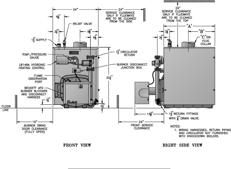
Figure 1A: V82 thru V89 Water Boiler without Tankless Heater
7
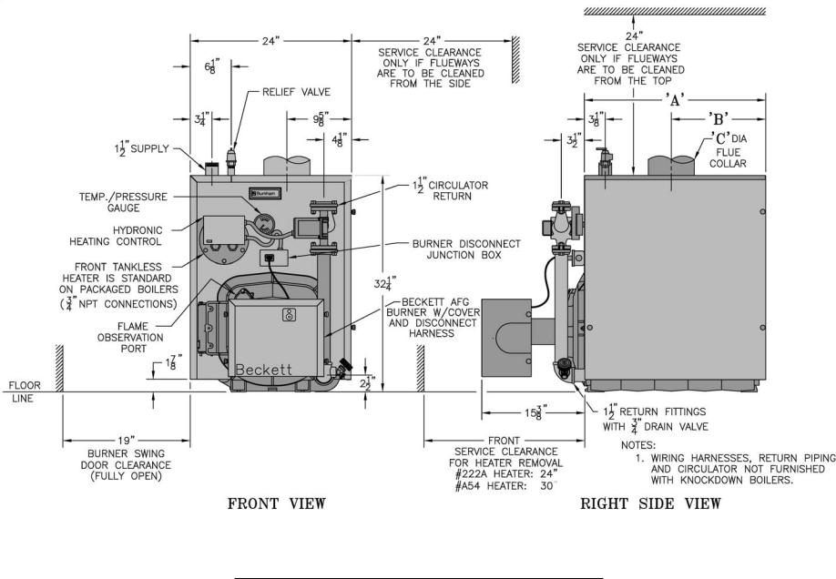
Figure 1B: V83 thru V89 Water Boiler with Front Tankless Heater
8
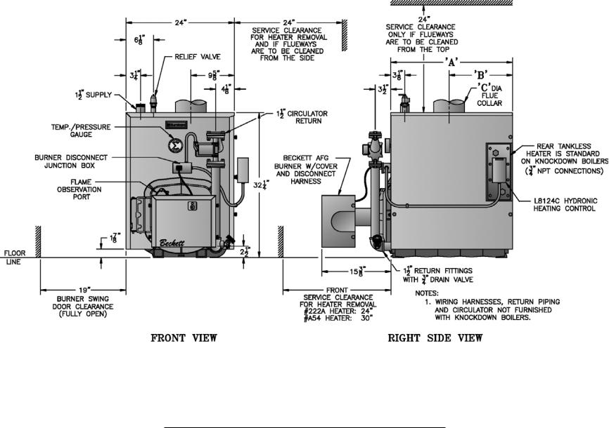
Figure 1C: V83 thru V89 Water Boiler with Rear Tankless Heater

Figure 1D: V83 thru V89 Steam Boiler with or without Tankless Heater
9
SECTION I: PRE-INSTALLATION
A.INSPECT SHIPMENT carefully for any signs of damage.
1.All equipment is carefully manufactured, inspected and packed. Our responsibility ceases upon delivery of crated boiler to the carrier in good condition.
2.Any claims for damage or shortage in shipment must be filed immediately against the carrier by the consignee. No claims for variances from, or shortage in orders, will be allowed by the manufacturer unless presented within sixty (60) days after receipt of goods.
B.LOCATE BOILER in front of final position before removing crate. See Figures 1A thru 1D.
1.LOCATE so that vent pipe connection to chimney will be short and direct.
2.BOILER IS SUITABLE FOR INSTALLATION ON COMBUSTIBLE FLOOR. Boiler cannot be installed on carpeting.
3.FOR BASEMENT INSTALLATION, provide a solid elevated base, such as concrete, if floor is
not level, or if water may be encountered on floor around boiler.
4.PROVIDE SERVICE CLEARANCE of at least 24” clearance from front jacket panel for servicing and removal of front tankless heater (increase to 30" for #A54 heater). If boiler is equipped with
a rear tankless heater, provide at least 24" service clearance on the right side of the boiler. Boiler flueways may be cleaned either from the top or from the right side. Provide at least 24" clearance from either the right side of the boiler or the top of the boiler for cleaning flueways.
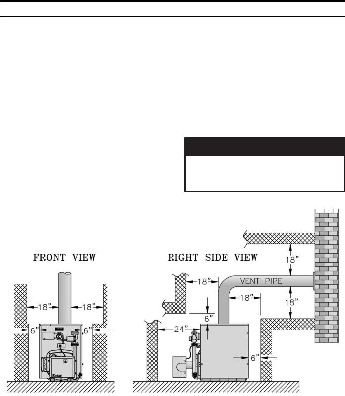
5.For minimum clearances to combustible materials. See Figure 2.
NOTICE
Clearance to venting is for single wall vent pipe. If Type L vent is used, clearance may be reduced to the minimum required by the vent pipe manufacturer.
Figure 2: Minimum Installation Clearances To Combustible Materials (Inches)
NOTES:
1.Listed clearances comply with American National Standard ANSI/NFPA 31, Installation of Oil Burning Equipment.
2.V8 Series boilers can be installed in rooms with clearances from combustible material as listed
above. Listed clearances cannot be reduced for alcove or closet installations.
3.For reduced clearances to combustible material, protection must be provided as described in the above ANSI/NFPA 31 standard.
10
C.PROVIDE COMBUSTION AND VENTILATION AIR. Local and National Codes may apply and should be referenced.
WARNING
Adequate combustion and ventilation air must be provided to assure proper combustion and to maintain safe ambient air temperatures.
Do not install boiler where gasoline or other flammable vapors or liquids, or sources of hydrocarbons (i.e. bleaches, fabric softeners, etc.) are used or stored.
1.Determine volume of space (boiler room). Rooms communicating directly with the space in which the appliances are installed, through openings not furnished with doors, are considered a part of the space.
Volume(ft3) = Length(ft) x Width(ft) x Height(ft)
2.Determine total input of all appliances in the space.
Add inputs of all appliances in the space and round the result to the nearest 1000 BTU per hour.
3.Determine type of space. Divide Volume by total input of all appliances in space. If the result is greater than or equal to 50 ft3/1000 BTU per hour, then it is considered an unconfined space. If the result is less than 50 ft3/1000 BTU per hour then the space is considered a confined space.
4.For boiler located in an unconfined space of a conventionally constructed building, the fresh air infiltration through cracks around windows and doors normally provides adequate air for combustion and ventilation.
5.For boiler located in a confined space or an unconfined space in a building of unusually tight construction, provide outdoor air.
a.Outdoor air for combustion may be provided with an optional Burnham V8 Inlet Air Accessory Kit, Part Number 611280031 (ONLY AVAILABLE WITH BECKETT BURNER). See Section VII for installation details.
or
b.Outdoor air may be provided with the use of two permanent openings which communicate directly or by duct with the outdoors or spaces (crawl or attic) freely communicating with the outdoors. Locate one opening within 12 inches of top
of space. Locate remaining opening within 12 inches of bottom of space. Minimum dimension of air opening is 3 inches. Size each opening per following:
i. Direct communication with outdoors.
Minimum free area of 1 square inch per 4,000 BTU per hour input of all equipment in space.
ii. Vertical ducts. Minimum free area of 1 square inch per 4,000 BTU per hour input of all equipment in space. Duct cross-sectional area shall be same as opening free area.
iii. Horizontal ducts. Minimum free area of 1 square inch per 2,000 BTU per hour input of all equipment in space. Duct cross-sectional area shall be same as opening free area.
Alternate method for boiler located within confined space. Use indoor air if two permanent openings communicate directly with additional space(s) of sufficient volume such that combined volume of all spaces meet criteria for unconfined space. Size each opening for minimum free area of 1 square inch per 1,000 BTU per hour input of all equipment in spaces, but not less than 100 square inches.
6.Louvers and Grilles of Ventilation Ducts
a.All outside openings should be screened and louvered. Screens used should not be smaller than 1/4 inch mesh. Louvers will prevent the entrance of rain and snow.
b.Free area requirements need to consider the blocking effect of louvers, grilles, or screens protecting the openings. If the free area of the louver or grille is not known, assume wood louvers have 20-25 percent free area and metal louvers and grilles have 60-75 percent free area.
c.Louvers and grilles must be fixed in the open position, or interlocked with the equipment to open automatically during equipment operation.
11
SECTION II: KNOCKDOWN BOILER ASSEMBLY
A.REMOVAL OF BARE BOILER FROM SKID
1.Boiler is secured to skid with 4 bolts, 2 in front and 2 in rear of shipping skid, see Figure 3. Remove all bolts.
Figure 3: Knockdown Boiler Removal from Skid
2.Tilt boiler to right and to rear. Using right rear leg as pivot, rotate boiler 90° in a clockwise direction, and lower left side of boiler to floor. Tilt boiler and remove skid.
B.MOVE BOILER TO PERMANENT POSITION by sliding or walking.
C.TEST BOILER FOR LEAKS before installing controls, trim, and jacket, and before connecting to heating system.
1.Loosen nuts on tie rods until only finger tight.
2.Install pressure gauge (at least 50 PSI capacity), a hose to the city water and a valve in the supply tapping. Plug remainder of tappings.
3.Fill boiler with water and apply a pressure of at least 10 PSI but no more than 50 PSI gauge pressure.
WARNING
Assure that there is no air left inside boiler when checking for leaks. Do not test for leaks with pressurized air.
4.Examine boiler carefully inside and outside for leaks or damage due to shipment or handling.
D.DRAIN WATER FROM BOILER. Remove gauge, valve and plugs from those tappings to be used. Leave other tappings plugged or bushed according to Figure 5.
E.INSPECT JOINTS BETWEEN SECTIONS. All joints are factory sealed. If there are any spaces due to shipment or handling, seal them with boiler putty.
F. INSPECT FLUE COVER PLATES for tightness. If loose, retighten mounting hardware. If flue plate or sealing rope is damaged, repair or replace as needed.
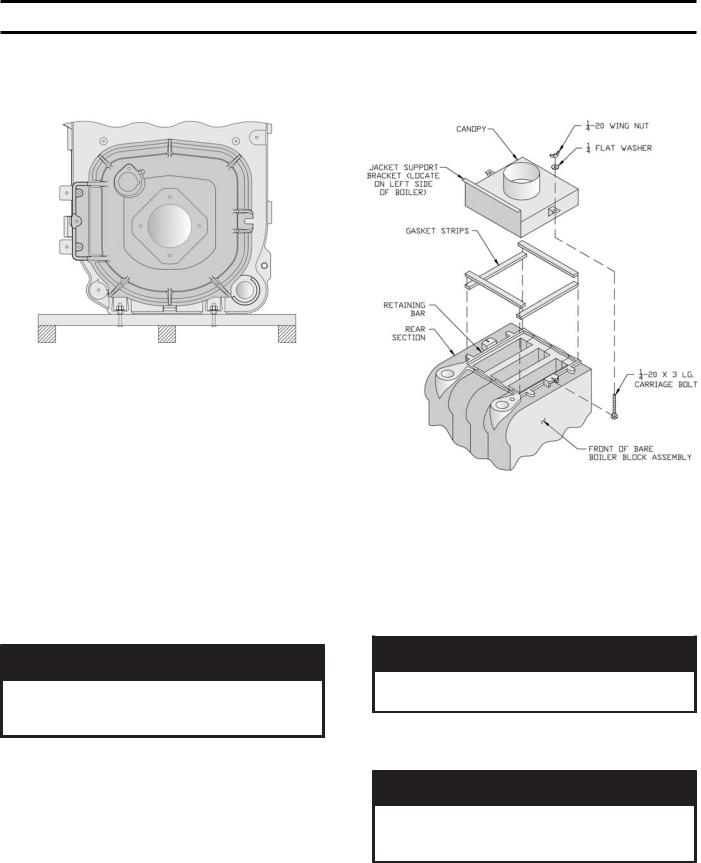
G.INSTALL AND SECURE CANOPY with gasket and hardware provided to ensure gas tight seal — see Figure 4.
Figure 4: Boiler Canopy Installation
1.Cut two (2) strips 13 ¾” long from the roll of gasket insulation. Place one (1) strip across the top of the front section and the other across the rear section as shown in Figure 4.
2.Cut the remainder of the roll into two (2) equal pieces. Place each piece along the sides, allowing the ends to overlap the front and rear pieces.
CAUTION
Do not allow any flueway blockage by gasket.
3.Position canopy body within the retaining bar which borders the flueway openings on top of the bare boiler block assembly.
NOTICE
Jacket support bracket must be facing left side of boiler - see Figure 4. Jacket will not fit if bracket is not oriented correctly.
4.Secure canopy to boiler with two (2) 1/4" - 20 x 3" long carriage bolts, 1/4" flat washers and 1/4" - 20 wing nuts provided.
12
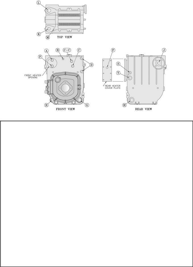
Figure 5: Boiler Tapping Locations and Usage (Knockdown Boilers Only)
PURPOSE OF TAPPINGS
Tapping |
Size |
Steam Boiler |
|
Water Boiler |
|
||
|
|
|
|
|
|||
Location |
NPT |
Non-Heater |
w/Heater |
Non-Heater |
Front Heater |
Rear Heater |
|
|
|
||||||
|
|
|
|
|
|
|
|
A |
¾" |
Pressure Limit (Probe LWCO) |
L8148A |
L8124C |
Flush Plug |
||
Plugged (Float LWCO) |
Operating Control |
Operating Control |
|||||
|
|
|
|||||
|
|
|
|
|
|
|
|
B |
¼" |
Pressure Gauge |
Temperature/Pressure Gauge |
||||
|
|
|
|
|
|
|
|
C |
¾" |
Probe LWCO Std. |
|
N/A |
|
||
Plugged (Float LWCO) |
|
|
|||||
|
|
|
|
|
|||
|
|
|
|
|
|
|
|
C-C |
¾" |
Flush Plug |
Flush Plug |
|
N/A |
|
|
|
|
|
|
|
|
|
|
D |
½" |
Water Gauge Glass (Probe LWCO) |
|
N/A |
|
||
Water Gauge Glass, Pressuretrol, and LWCO (Float) |
|
|
|||||
|
|
|
|
|
|||
|
|
|
|
|
|
|
|
F |
¾" |
N/A |
L4006A Operating Control |
N/A |
N/A |
L8124C |
|
Operating Control |
|||||||
|
|
|
|
|
|
||
|
|
|
|
|
|
|
|
G |
1½" |
Bushed to ¾" for Drain Valve (Optional Return) |
|
Return |
|
||
|
|
|
|
|
|
|
|
H |
1½" |
Return |
|
Plugged |
|
||
|
|
|
|
|
|
|
|
J |
1½" |
Surface Blowoff - Plugged |
|
Flush Plug |
|
||
|
|
|
|
|
|
|
|
K |
2" |
Front Supply (3 thru 9 Section) |
Front Supply (3 thru 9 Section) |
||||
|
|
|
|
|
|
|
|
L |
2" |
Plugged, Optional Second Supply (3 thru 5 Section) |
Plugged (3 thru 9 Section) |
||||
Required Second Supply (6 thru 9 Section) |
|||||||
|
|
|
|
|
|||
|
|
|
|
|
|
|
|
M |
¾" |
Safety Valve |
|
Relief Valve |
|
||
|
|
|
|
|
|
|
|
P |
¾" |
Auxiliary Tapping - Plugged |
Aux. Tapping - |
N/A |
Aux. Tapping - |
||
Plugged |
Plugged |
||||||
|
|
|
|
|
|||
|
|
|
|
|
|
|
|
R |
¾" |
Aux. Tapping - Plugged |
Aux. Tapping - Plugged |
Auxiliary Tapping - Plugged |
|||
(Indirect Return) |
(Indirect Return) * |
||||||
|
|
|
|
|
|||
|
|
|
|
|
|
|
|
S |
½" |
Indirect Limit |
Indirect Limit * |
|
N/A |
|
|
|
|
|
|
|
|
|
|
T |
1" |
Indirect Supply |
Indirect Supply * |
|
N/A |
|
|
|
|
|
|
|
|
|
|
* In lieu of Tankless Heater
13
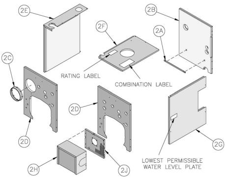
Figure 6: Knockdown Boiler Jacket Assembly
H.INSTALL TRIM. The following steam or water trim will be concealed or inaccessible after boiler jacket is installed, see Figure 5 for boiler tapping locations and usage.
1.STEAM BOILER — Top tappings:
a.Tapping "L" — Install 2" NPT plug in rear section top supply tapping on boiler sizes V83 thru V85, if only one supply riser is used.
b.Tapping “M” — Install ¾” NPT coupling and ¾” NPT x 8” long nipple into ¾” NPT tapping located next to front section top supply tapping
— all boiler sizes.
2.WATER BOILER — Top tappings:
a.Tapping “L” — Install 2” NPT plug in rear section top supply tapping — all boiler sizes.
b.Tapping “M” —Install ¾” NPT x 8” long nipple into ¾” NPT tapping located next to front section top supply tapping — all boiler sizes.
I.INSTALL BOILER JACKET. (See Figure 6).
1.Remove burner swing door and hinge assembly. Remove one (1) 5/16"-18 flange nut and washer from right side latching stud and one (1) 5/16"- 18 x 3½" cap screw on left side used for securing
burner swing door to the boiler section. Swing door open and remove 5/16" hairpin cotter from rear hinge pin. While holding swing door remove hinge pin and set door aside. Remove two (2) 5/16" -
18 x ¾" long cap screws securing the hinge bracket to the boiler section.
2.Install jacket rear panel support bracket. (See Figure 6, Item 2A). Align bracket with two (2) 5/16" - 18 tapped holes in rear section and secure with two (2) 5/16" - 18 x 1/2" long cap screws.
3.Install jacket rear panel. (See Figure 6, Item 2B). Align holes in jacket rear panel and support bracket. Secure with two (2) #8 x 1/2" long sheet metal screws.
4.Jacket Front Panel
a.Install black plastic collar extension to jacket front panels for 7-13/16" diameter tankless heater opening. (See Figure 6, Items 2C and 2D). Engage two (2) of the collar retaining tabs over raw edge of jacket opening. Provide support behind the panel with one hand while applying pressure on collar to snap each tab over edge of opening until all eight (8) tabs are securing collar.
b.Install jacket front panel. Locate two (2) 11/32" diameter holes, one round, one obround, on front panel approximately 16” up from the bottom of the panel. Align these holes with the similarly located 5/16" - 18 tappings on the front section. Secure with two (2) 5/16" - 18 x 1/2" long cap screws.
5.Install jacket left side panel. (See Figure 6, Item 2E). Fold panel at perforation keeping insulation inward. Align left side panel mounting holes with the front and rear panel holes. Secure with #8 x ½” long sheet metal screws.
14
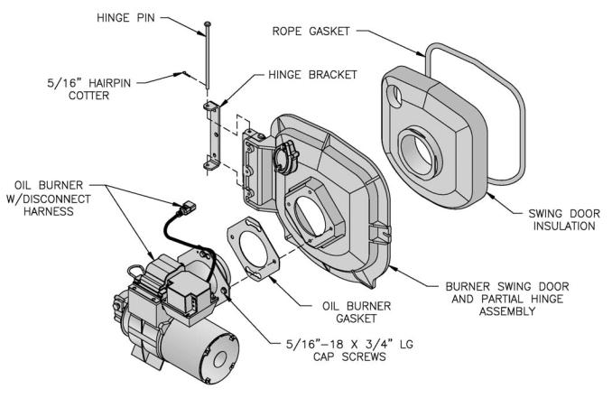
Figure 7: Oil Burner Installation (Beckett Burner Shown)
6.Install jacket top panel. (See Figure 6, Item 2F). Place jacket top panel on boiler and secure to front, rear and left side panels with #8 x ½” long sheet metal screws.
7.Install jacket right side access panel. (See Figure 6, Item 2G). Align right side panel mounting holes with front and rear panel holes. Secure with #8 x ½” long sheet metal screws.
8.Attach the labels shipped in the instruction envelope as follows:
a.Locate both the Rating Label and Combination Warning Label (P/N 8142803). Remove paper backing from the labels and apply to the jacket top panel in approximate locations shown in (Figure 6, Item 2F).
b.On steam boilers only; locate Lowest Permissible Water Level Plate (Form No. 1204 shipped in Steam Trim Carton). Align plate with two 1/8" diameter holes located near the front edge; in line with the lower sight glass tapping, of the jacket right side access panel. Attach plate with two (2) #8 x 1/2" long sheet metal screws. (See Figure 6, Item 2G).
J.INSTALL BECKETT OIL BURNER. (See Figure 7).
1.Check target wall and combustion chamber blanket. If any damage or movement occurred during shipment, replace as needed.
2.Locate burner swing door and hinge assembly removed in Paragraph I, No. 1. Check the burner swing door insulation and rope gasket for damage and adhesion. If damaged, replace insulation or gasket. If insulation or gasket is loose, reattach to swing door with RTV 732 or 736 silicone caulk.
3.Install burner swing door in reverse order from Paragraph I, No. 1.
4.Use the following procedure to properly close and secure the burner swing door after it has been removed and re-installed for Field Assembly (Knockdown Boiler) or opened for inspection, cleaning or field service (refer to Figures 11A and 11B):
Step 1. Lift the door up unto the built-in cast ramp/ door rest (protruding from the bottom of the front section casting - see Figure 11A), while rotating the articulated hinge and door to the right and engaging the slot (on right side of door) unto the 5/16" stud protruding from the front section.
Step 2. Use one hand to help hold door in position by applying pressure directly to the door while re-installing the securing hardware with your opposite hand. Always install right side latching hardware (5/16" flange nut and flat washer) first, then install left side hinge hardware (5/16" x 3-1/2" lg. hex head flange bolt) second. Apply additional pressure while hand tightening the hardware as far as possible,
then release the pressure. |
15 |
|

NOTICE
When securing burner swing door make sure door is drawn-in equally on both sides.
Step 3. Use a hand wrench to tighten door hardware and always start with the right side flange
nut first (see figure 11B). Use an alternating tightening method from right side flange nut to left side flange bolt to tighten door equally until sealed without applying excessive torque.
Never tighten left side flange bolt first or tighten either piece of hardware 100% without using the alternating tightening method described above.
5. Place oil burner gasket on burner and align holes.
CAUTION
Do not install burner without gasket.
6.Insert oil burner into the opening of the burner swing door. Align holes and install four (4) 5/16” - 18 x ¾” long cap screws. Level burner and fully tighten all four (4) screws.
7.Install oil nozzle in burner, inspect electrodes and head setting.
DANGER
The burner does not have an oil nozzle installed. The proper oil nozzle, supplied loose, must be installed in the nozzle adaptor. Do not operate burner without the proper oil nozzle installed in the burner.
a.Select the proper oil nozzle for the installation. Two (2) oil nozzles are supplied loose with each knockdown V83 - V86 boiler. Either nozzle may be used with water boilers. Steam boilers must use the lower input nozzle. The lower input nozzle will provide greater boiler efficiency
and for steam boilers, reduce boiler corrosion. However, boiler output will be reduced. Refer to Table 1B for ratings. The nozzle input is stamped on the hex flat of the nozzle.
CAUTION
Steam boilers must only be operated at the lower input. Increasing the firing rate above this input will result in accelerated boiler corrosion and will void the warranty provided with the boiler.
b.Loosen burner cover knobs and remove cover.
c.Loosen two (2) igniter latching screws, rotate tabs and swing open igniter about hinge.
d.Loosen knurled nut and disconnect copper connector tube.
e.Remove nozzle line electrode assembly.
f.Remove Beckett MD(V1) or MB(L1) Head.
g.Remove plug from nozzle adapter and install the proper nozzle. Refer to Table 6 for proper nozzle. The nozzle must be securely installed to assure leak free joints between the nozzle and adapter. When installing the nozzle, be careful not to bump or move the burner electrodes.
h.Inspect and measure burner electrodes. Refer to Figure 27A for the proper electrode setting. Readjust electrode setting to the proper dimensions if necessary.
i.Reinstall Beckett MD(V1) or MB(L1) Head.
j.Reinstall nozzle line electrode assembly.
k.Connect copper connector tube.
l.Inspect Beckett head setting on left side of burner by insuring the blue line MD(V1) or the line on the label MB(L1) are aligned, readjust if necessary.
m.Tighten knurled nut.
n.Swing igniter closed, rotate tabs and tighten two
(2) igniter screws.
o.Replace burner cover and tighten burner cover knobs.
K.INSTALL CARLIN 102CRD OIL BURNER. (See Figure 7).
Follow instructions in Paragraph J, Steps 1 through 6.
7.Install oil nozzle in burner, inspect electrodes and head setting.
DANGER
The burner does not have an oil nozzle installed. The proper oil nozzle, supplied loose, must be installed in the nozzle adaptor. Do not operate burner without the proper oil nozzle installed in the burner.
CAUTION
Steam boilers must only be operated at the lower input. Increasing the firing rate above this input will result in accelerated boiler corrosion and will void the warranty provided with the boiler.
Steam Boilers Only
Knockdown V87 - V89 boilers are provided with one nozzle, installed in the burner, that provides the same firing rate as the water boiler of the same size.
a.Installation/Removal of Drawer Assembly
i.Loosen screws, rotate latches and swing open the transformer.
16
Disconnect the flared fitting to the oil line and remove the aluminum thumb-nut from the nozzle line. Remove the combustion head assembly from the air tube. Rotating the assembly upside down will ease removal. Inspect the nozzle for size and type, refer to Table 6 of this manual.
ii.To change a nozzle, loosen the clamp screw on the retention ring assembly and slide the retention ring off the adaptor.
Install and tighten the proper nozzle in the adaptor. See Table 6 of this manual. Be careful not to damage the electrode insulators or to bend the wires.
iii.Replace the retention ring assembly, slipping one of the riveted arms through the 1/8-inch gap between the electrode tips. This arm should be straight up. Also, be sure that the retention ring clamp is tight against the shoulder on the adaptor. Then tighten the clamping screw.
iv.Check the electrode settings specified as follows and shown in Figure 27B. 1/8-inch gap, 1/4-inch above the nozzle centerline, and 3/16-inch ahead of the nozzle tip.
v.Re-install the combustion head assembly into the air tube. It may be necessary to turn nozzle line assembly upside down to ease insertion into the air tube. Then the threaded adapter on the end of the nozzle line is passed through the opening in the left side of the housing.
vi. Run the aluminum (knurled) thumb-nut onto the nozzle line and tighten hand-tight.
vii. Connect the flared fitting on the copper oil line to the nozzle line and tighten.
viii.Swing the transformer to the closed position, rotate latches and tighten screws.
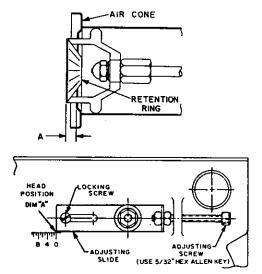
b.Combustion Head Setting/Adjustment
i.Verify combustion head setting, refer to Table 6 of this supplement. Read the scale embossed in the housing, which is calibrated in 1/16-inch divisions (dimension ‘A’)
the position of the flame retention ring in relation to the air cone can be determined at a glance. Refer to Figure X.
ii.By moving the electrode and combustion head assembly forward or backward, the location of the flame retention ring relative to the throttle ring can be controlled. Refer to Figure 7A.
By loosening the locking screw and thumbnut and turning the adjusting screw using a 5/32-inch allen wrench, the assembly can be
Figure 7A: Combustion Head Adjustment
moved to the required position.
Turn the adjusting crew clockwise to move the combustion head forward, increasing the ‘A’ dimension, counterclockwise will pull the head back, decreasing the ‘A dimension. To lock in place, first tighten the thumb-nut and then the locking screw.
c.Initial Air Shutter/Band Setting
i.The air shutter has a pointer which indicated the percent of opening against a calibrated scale (9 = 90%, fully open = 100%). The setting is locked in place by a screw just above the fuel unit.
ii.The air band is adjusted by loosening the screw, rotating the air band and then locked in place after final adjustment. Refer to Table 6 of this manual for initial settings.
iii.The burner is now set at the approximate air band setting for the gallonage indicated. During final adjustment, using combustion testing equipment, the air band may need minor adjustment to achieve the desired efficiency.
Water Boilers Only
Knockdown V87 - V89 boilers are provided with one nozzle, installed in the burner, that provides the same firing rate as the steam boiler of the same size.
Inspect the installed nozzle and assure that the nozzle is the correct size and type as specified in Table 6 of this manual. The nozzle input is stamped on the hex flat of the nozzle.
Refer to Paragraph K, 7, a for burner drawer assembly removal.
17

L.INSTALL CARLIN ELITE EZ OIL BURNER.
(See Figure 7).
Follow instructions in Paragraph J, Steps 1 through 6.
7.Inspect oil nozzle, electrodes and head setting/ change firing rate.
DANGER
The burner does not have an oil nozzle installed. The proper oil nozzle, supplied loose, must be installed in the nozzle adaptor. Do not operate burner without the proper oil nozzle installed in the burner.
CAUTION
Steam boilers must only be operated at the lower input. Increasing the firing rate above this input will result in accelerated boiler corrosion and will void the warranty provided with the boiler.
Steam Boilers Only
Steam boilers must use the lower input nozzle. The lower input nozzle will provide greater boiler efficiency and for steam boilers, reduce boiler corrosion. However, boiler output will be reduced.
Burners for knockdown V83 - V86 steam boilers are shipped with the lower (standard) firing rate nozzle installed. Knockdown V87 - V89 boilers are provided with one nozzle, installed in the burner, that provides the same firing rate as the water boiler of the same size.
a.Installation/Removal of Drawer Assembly
i.Loosen screws, rotate latches and swing open the transformer.
ii.The combustion head assembly can be removed with the blower wheel access cover in place or removed. If the access cover is removed, the head assembly will not have to be rotated.
Disconnect the flared fitting to the oil line and remove the aluminum thumb-nut from the nozzle line. Remove the combustion head assembly from the air tube. Rotating the assembly upside down will ease removal.
iii.Loosen the clamp screw on the retention ring assembly and slide the retention ring off the adaptor.
Install and tighten the proper nozzle in the adaptor. See Table 6 of this manual. Be careful not to damage the electrode insulators or to bend the wires.
iv.Replace the retention ring assembly, slipping one of the riveted arms through the 1/8-inch gap between the electrode tips. This arm should be straight up. Also, be sure that
the retention ring clamp is tight against the shoulder on the adaptor. Then tighten the clamping screw.
v.Check the electrode settings specified as follows and shown in Figure 27C. 1/8-inch gap, 1/4 to 5/16-inch above the nozzle centerline, and flush to 1/16-inch ahead of the nozzle tip.
vi.Re-install the combustion head assembly holding it upside down while inserting into the housing. The flame retention ring end of the assembly must be lifted and guided through the throttle cone (a reduced diameter) in the end of the air tube. DO NOT FORCE IT.
vii.After attaching the proper positioning bar, refer to Paragraph 7,b, run the thumb-nut onto the nozzle line and tighten it lightly. Connect the flared fitting on the copper oil line to the nozzle line and tighten.
b.Combustion Head Positioning Bars
i.The Elite EZ-1HP and EZ-2HP burners are supplied with the proper positioning bar installed onto the housing that matches the high (standard) input oil nozzle installed in the burner. A second positioning bar and nozzle for the lower (minimum) firing rate is shipped loose for the V83-V86 models, attached the burner.
Verify that the installed positioning bar matches the high input oil nozzle installed in the burner or replace them both with the nozzle and positioning bar that matches the lower firing rate, refer to Table 6 of this manual.
The remaining bar(s) should be placed in the rear of the housing or junction box for future use in the event the firing rate must be changed.
In the case of the EZ-1HP, the proper head positioning bar is still matched by the size of the nozzle, not the input. For example, if nozzle size is 0.75 GPH, input @ 150 psi is approximately 0.90 GPH and the proper bar is 0.75 GPH.
ii.Model EZ-1HP Positioning Bars: 0.50 GPH, 0.60-0.65 GPH, 0.75 GPH, 0.85-1.00 GPH, 1.10-1.25 GPH, 1.35-1.50 GPH, 1.65 GPH.
iii.Model EZ-2HP Positioning Bars: 1.50 GPH, 1.65-1.75 GPH, 2.00 GPH, 2.25 GPH.
18

c.Initial Air Band Setting
i.The nozzle size in GPH INPUT is printed directly on the air band. Loosen the locking screw, move the air band until the pointer on the air shutter and housing lines up with the appropriate GPH INPUT. Tighten the locking screws.
ii.The Elite burners use calibrated air bands marked in nozzle sizes. Models EZ-1HP and EZ-2HP have air bands calibrated to deliver the proper amount of air for their specific pump pressure. The air bands on H.P. models are designed to be set by the rating stamped on the nozzle.
iii.The burner is now set at the approximate air band setting for the gallonage indicated. During final adjustment, using combustion testing equipment, the air band may need minor adjustment to achieve the desired efficiency.
Water Boilers Only
Select the proper oil nozzle for the installation. Burners for knockdown V8 water boilers are shipped with the high (standard) input oil nozzle installed in the burner.
A second oil nozzle for the lower (minimum) firing rate is shipped loose for the V83 - V86 models, attached to the burner. Either nozzle may be used with water boilers. The lower (minimum) input nozzle will provide greater boiler efficiency. However, boiler output will be reduced. Refer to Table 1B for firing rates. If the higher rate is desired, inspect the installed nozzle and assure that the nozzle is the correct size and type as specified in Table 6 of this manual. The nozzle input is stamped on the hex flat of the nozzle.
If the lower (minimum) input is desired, remove the nozzle which was factory installed. Locate the lower (minimum) firing rate nozzle that is supplied loose. Confirm the nozzle is the proper size and type for the lower firing rate as specified in Table 6 of this manual. Install the proper nozzle in the burner nozzle adaptor.
Refer to Step 7a for burner drawer assembly removal.
M.INSTALL RIELLO OIL BURNER. (See Figure 7). Follow instructions in Paragraph J, Steps 1 through 6.
7.Install oil nozzle in burner, inspect electrodes and head setting.
DANGER
The burner does not have an oil nozzle installed. The proper oil nozzle, supplied loose, must be installed in the nozzle adaptor. Do not operate burner without the proper oil nozzle installed in the burner.
CAUTION
Steam boilers must only be operated at the lower input. Increasing the firing rate above this input will result in accelerated boiler corrosion and will void the warranty provided with the boiler.
Steam Boilers Only
Steam boilers must use the lower input nozzle. The lower input nozzle will provide greater boiler efficiency and for steam boilers, reduce boiler corrosion. However, boiler output will be reduced.
Burners for knockdown V83 - V86 steam boilers are shipped with the lower (standard) firing rate nozzle installed. Knockdown V87 - V89 boilers are provided with one nozzle, installed in the burner, that provides the same firing rate as the water boiler of the same size.
a.Installation/Removal of Drawer assembly, refer to Figure 7B.
Figure 7B: Installation/Removal of Drawer Assembly
i.Removal:
•Disconnect oil delivery tube nut from pump.
•Loosen SCREW (3), and then unplug PRIMARY CONTROL (1) by carefully pulling it back and then up.
•Remove the AIR TUBE COVER PLATE (5) by loosening the retaining SCREW (4) (Two SCREWS-Model F5).
•Loosen SCREW (2), and then slide the complete drawer assembly out of the
combustion head as shown. ii. Installation:
To insert drawer assembly, reverse the procedure in Step i above.
b. Nozzle Replacement, refer to Figure 7C.
19
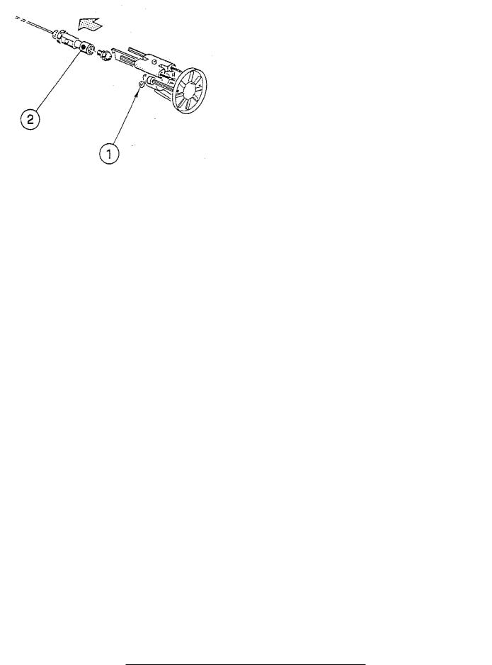
Figure 7C: Nozzle Replacement
i.Remove the nozzle adapter (2) from the drawer assembly by loosening the screw (1).
ii.Remove existing nozzle from nozzle adapter.
iii.Insert the proper nozzle into nozzle adapter and tighten securely (Do not over tighten).
iv.Replace adapter, with nozzle installed, into drawer assembly and secure with screw (1).
c.Inspect and measure burner electrodes. Refer to Figure 27D for the proper electrode settings.
d.Re-install Drawer Assembly into Comustion Head per Step 7c above.
e.Insertion Depth, verify the distance between the tip of the end cone is equal to the distance specified in Table 6 of this manual.
f.Turbulator Setting, refer to Figure 7D.
i.Confirm the turbulator setting is correct for standard higher (maximum) input oil nozzle installed in the burner. If the
lower (minimum) input is desired, readjust turbulator setting to index mark specified in Table 6 of this manual.
ii.Loosen nut (1) and turn screw (2) until the index marker (3) is aligned with the correct index number in the Burner Setup Chart (Table 6).
Figure 7D: Turbulator Setting
iii. Retighten the retaining nut (1).
MODEL F3 NOTE: Zero and three are scale indicators only. From left to right the first line is 3 and the last line 0.
MODEL F5: Same as above, except, scale indicators are 0 and 4.
MODEL F10: Same as above, except, scale indicators are 0 and 5.
i.Pump Connections and Port Identification, refer to Figure 7E.
This burner is shipped with the oil pump set to operate on a single line system. To operate on a two-line system the bypass plug must be installed.
WARNING: Do not operate a single line system with the by-pass plug installed. Operating a single line system with the by-pass plug installed will result in damage to the pump shaft seal.
NOTE: Pump pressure was factory pre-set but must be checked at time of burner start-up. A pressure gauge is attached to the PRESSURE/ BLEEDER PORT (7) for pressure readings. Two PIPE CONNECTORS (4) are supplied with the burner for connection to either a single or twoline system. Also supplied are two ADAPTORS (3), two female ¼” NPT to adapt oil lines to burner pipe connectors. All pump port threads are British Parallel Thread design. Direct connection of NPT threads to the pump will damage the pump body.
Figure 7E: Pump Connections and Port Identification
20
Riello manometers and vacuum gauges do not require any adapters, and can be safely connected to the pump ports. An NPT x metric adapter must be used when connecting other gauge models.
g.Replace Burner Cover and Tighten Burner Cover Screws.
Water Boilers Only
Select the proper oil nozzle for the installation. Burners for knockdown V8 water boilers are shipped with the high (standard) input oil nozzle installed in the burner.
A second oil nozzle for the lower (minimum) firing rate is shipped loose for the V83 - V86 models, attached to the burner. Either nozzle may be used with water boilers. The lower (minimum) input nozzle will provide greater boiler efficiency. However, boiler output will be reduced. Refer to Table 1B for firing rates. If the higher rate is desired, inspect the installed nozzle and assure that the nozzle is the correct size and type as specified in Table 6 of this manual. The nozzle input is stamped on the hex flat of the nozzle.
If the lower (minimum) input is desired, remove the nozzle which was factory installed. Locate the lower (minimum) firing rate nozzle that is supplied loose. Confirm the nozzle is the proper size and type for the lower firing rate as specified in Table 6 of this manual. Install the proper nozzle in the burner nozzle adaptor.
Proceed to Step c for burner drawer assembly removal.
N.INSTALL TRIM AND CONTROLS WITH BECKETT BURNER. - Steam Boiler Only (see Figures 1D & 5).
1.Thread the pressure gauge into the ¼” NPT tapping "B", of the front section. Tighten with wrench applied to the square shank of the gauge.
CAUTION
Do not apply pressure to the gauge case - this may result in inaccurate readings.
2.Thread 1½” NPT x ¾” NPT bushing and a ¾” NPT drain valve into the 1½” NPT tapping located in the lower right corner of the front section. Tighten with wrench.
NOTICE
Lower rear section Tapping "H" is used for standard condensate return on steam boilers.
3.Thread safety valve, as shown in Figure 1D, into ¾" NPT coupling and ¾” NPT x 8” nipple previously installed in Paragraph H, No. 1, step b. Tighten with wrench. Pipe discharge as shown in Figure 14. Installation of the safety (relief) valve must be consistent with ANSI/ASME Boiler and Pressure Vessel Code, Section IV.
WARNING
Safety valve discharge piping must be piped near floor to eliminate potential of severe burns. Do not pipe in any area
where freezing could occur. Do not install any shut-off valves, plugs or caps.
4.Install probe type Low Water Cut-Off (LWCO) if so equipped.
WARNING
Read the manufacturer’s instructions packed with the probe LWCO for proper pipe dope application. DO NOT use Teflon tape on probe threads. Use of teflon can render the probe LWCO inoperational.
a.Thread probe into ¾” NPT tapping "C" located on the front section, down and to the right of the pressure gauge. Slip the low water cut-off (LWCO) control over the probe and clamp in
place. Connect the wire(s) between the probe and control per the manufacturer’s instructions.
b.Install the gauge glass using the two ½” NPT tappings to the right of the probe LWCO.
5.Install float-type LWCO, if so equipped. See Figure 8.
a.Install nipples and unions in "D" Tappings.
b.Mount hardware to low water cut-off body. Install assembly.
c.Install water gage glass on low water cut-off assembly's tee fittings.
6.Install Pressure Limit Control.
a.Float LWCO only: Remove ¼" NPT plug from top of Low Water Cut-Off. Install Syphon and Limit into this tapping. See Figure 8.
b.Probe LWCO only: Install Limit in Tapping "A" using ¾" NPT x 3" long nipple, ¾" NPT elbow, ¾" NPT x ¼" NPT bushing, and syphon. See Figure 9.
c.Do not tighten the limit by holding the case; apply a wrench to the brass hex below the case.
d.Level an L404A pressure limit by carefully bending the syphon until the limit's leveling indicator hangs freely with its pointer directly over the index mark inside the back of the case.
21
Figure 8: Float-Type Low Water Cut-Off and
Pressure Limit Installation
Figure 9: Pressure Limit Installation for Probe LWCO Equipped Boilers
NOTICE
L404A Pressure Limits contain mercury in a sealed tube. Do not place limit in the trash at the end of its useful life.
If this limit is replacing a limit that contains mercury in a sealed tube, do not place your old limit in the trash.
Contact your local waste management authority for instructions regarding recycling and the proper disposal of this limit, or of an old limit containing mercury in a sealed tube.
If you have questions, call Honeywell Inc. at
1-800-468-1502.
e.An L404F pressure limit does not require leveling.
7.On units with a heater opening, install the aquastat controller well in the ½" NPT or ¾” NPT tapping in tankless heater plate or cover plate. Slip the bulb of the aquastat into the well and secure the control in place with the set screw.
WARNING
Aquastat bulb must be fully inserted into the well.
8.Connect the field wiring to the pressure limit, the LWCO, the R8239A Control Center/J-box and the burner J-box or burner disconnect J-box.
If equipped with tankless heater, connect field wiring from the aquastat control to the R8239A Control Center transformer terminals or oil burner primary control's "T-T" terminals.
Make the wiring connections as shown in Figures 19, 20 and 21.
NOTE:
•The R7184P Primary Control has pre-installed "T-T" jumper resistor. To activate "T-T" terminals, "T-T" jumper must be removed. To remove, use side cutting pliers to cut jumper (see Figure 28).
•Do not remove (cut) "T-T" jumper unless wiring diagram indicates a direct connection from thermostat and/or tankless heater aquastat control to the oil burner primary control's "T-T" terminals.
Refer to Paragraph S for details on use of burner disconnect junction box provided with all knockdown boiler builds.
O.INSTALL TRIM AND CONTROLS WITH BECKETT BURNER. - Water Boilers Only (See Figures 1A, 1B, 1C and 5).
1.Thread ½” NPT pipe plugs into gauge glass tappings in the upper right side of front section.
2.Thread ¾” NPT pipe plug in probe low water cut off tapping (just left of gauge glass tappings).
3.Thread combination pressure/temperature gauge into ¼” NPT tapping. Tighten with wrench applied to the square shank of the gauge.
CAUTION
Do not apply pressure to the gauge case - this may result in inaccurate readings.
4.Screw drain valve into ¾" NPT side outlet of the 1½” NPT x 90° elbow (note - lower front section tapping “G” is used for standard return on water boilers).
5.If circulator (not supplied with boiler) is to be mounted directly to 1½" NPT boiler return tapping "G", use the piping arrangements outlined in steps a. thru e. as follows: (see Figures 13A, 13B and 13C)
a.Thread 1½” NPT x 3” long nipple and 1½”
NPT x 90° elbow with ¾" NPT side outlet into the return tapping and tighten with a pipe wrench.
22

b.Thread 1½” NPT x 15” long nipple into the 1½" NPT x 90° elbow and tighten with a pipe wrench.
c.Thread one of the circulator flange onto the nipple and tighten with a pipe wrench. Position flange so that the bolt slots are parallel to the boiler front.
d.Place a circular flange gasket in the flange groove on the circulator and mount the circulator on the flange. Note that this is the return piping and the flow arrow on the circulator should point down Ð. Fasten circulator with 7/16” - 14 x 1½" long cap screws and 7/16" - 14 nuts.
e.Fasten the second circulator flange and gasket to the circulator.
6.Install relief valve, as shown in Figure 1A, 1B, and 1C, onto ¾” NPT x 8” nipple previously installed in Paragraph H, No. 2, step b. Tighten with wrench.
Pipe discharge as shown in Figures 13A, 13B and 13C. Installation of the relief valve must be consistent with ANSI/ASME Boiler and Pressure Vessel Code, Section IV.
WARNING
Safety valve discharge piping must be piped near floor to eliminate potential of severe burns. Do not pipe in any area
where freezing could occur. Do not install any shut-off valves, plugs or caps.
7.On units without a heater opening, install the well into the ¾” NPT tapping "A" located on the front of the boiler in the upper left corner. See Figures 1A and 5. Tighten the well and insert the control’s bulb into the well. Secure control to well with set screw.
WARNING
Aquastat bulb must be fully inserted into the well.
8.On units with a heater opening, install the well in the ½" NPT or ¾” NPT tapping on the tankless heater plate or cover plate. See Figures 1B, 1C and 5. Tighten the well and insert the control’s bulb into the well. Secure control to well with set screw.
9.Connect Field Wiring.
a.Water boilers without tankless heater and with front tankless heater. Connect the field wiring from the circulator to the aquastat control and from the control to the burner disconnect J-box or directly to the burner J-box. Make the wiring connections as shown on Figures 22, 23A and 23D.
b.Water boilers with rear tankless heater. Connect the field wiring from a standard junction box
or burner disconnect J-box to the circulator, aquastat control and burner. Make the wiring connections as shown on Figure 23B.
NOTE:
•Do not remove (cut) "T-T" jumper on R7184P Primary Control for application 9a or 9b above.
c.Refer to Paragraph S for details on use of burner disconnect junction box provided with all knockdown boiler builds.
P.INSTALL TRIM AND CONTROLS WITH CARLIN 102CRD BURNER.
Follow instructions in Paragraph N, Steps 1 through 7. Steam Boilers Only (see Figures 1D and 5).
8.Connect Field Wiring
a.Steam Boiler with Hydrolevel CG450 LWCO, Carlin Burner.
Connect the field wiring to the pressure limit, the LWCO, R8239C Control Center and the burner disconnect J-box or directly to burner J-box on burners less disconnect harness (power cord).
If equipped with tankless heater, connect field wiring from the aquastat control to the R8239C Control Center’s “R-G” terminals. Make the wiring connections as shown in Figure 19A.
b.Steam Boiler with McDonnell & Miller PS-801 or McDonnell & Miller 67 LWCO, Carlin Burner.
Connect the field wiring to the LWCO, the pressure limit and the burner disconnect J-box. If equipped with tankless heater, connect field wiring from the aquastat control to the oil burner primary control’s “T-T” Terminals. Make the wiring connections as shown in Figures 20A, and 21A.
c.Refer to Paragraph S for details on use of burner disconnect junction box provided with all knockdown boiler builds.
Water boilers Only (see Figures 1A, 1B, 1C and 5). Follow instructions in Paragraph O, Steps 1 through 7
9.Connect Field Wiring
a.Water boilers without tankless heater and with front tankless heater. Connect the field wiring from the circulator to the aquastat control and from the control to the burner disconnect J-box or directly to oil burner primary control on burners less disconnect harness (power cord). Make the wiring connections as shown on Figures 22A and 23B .
b.Water boilers with rear tankless heater. Connect the field wiring from a standard junction box
or burner disconnect J-box to the circulator, aquastat control and burner. Make the wiring connections as shown on Figure 23E.
c.Refer to Paragraph S for details on use of burner disconnect junction box provided with all knockdown boiler builds.
23
Q.INSTALL TRIM AND CONTROLS WITH CARLIN ELITE EZ BURNER.
Follow instructions in Paragraph N, Steps 1 through 7. Steam Boilers Only (see Figures 1D and 5).
8.Connect Field Wiring
a.Steam Boiler with Hydrolevel CG450 LWCO, Carlin Burner.
Connect the field wiring to the pressure limit, the LWCO, R8239C Control Center and the burner disconnect J-box or directly to burner J-box on burners less disconnect harness (power cord).
If equipped with tankless heater, connect field wiring from the aquastat control to the R8239C Control Center’s “R-G” terminals. Make the wiring connections as shown in Figure 19.
b.Steam Boiler with McDonnell & Miller PS-801 or McDonnell & Miller 67 LWCO, Carlin Burner.
Connect the field wiring to the pressure limit, the R8239C Control Center, the LWCO and the burner disconnect J-box. If equipped with tankless heater, connect field wiring from
the aquastat control to the oil burner primary control’s “T-T” Terminals. Make the wiring connections as shown in Figures 20 and 21.
c.Refer to Paragraph S for details on use of burner disconnect junction box provided with all knockdown boiler builds.
Water boilers Only (see Figures 1A, 1B, 1C and 5). Follow instructions in Paragraph O, Steps 1 through 7.
9.Connect Field Wiring
a.Water boilers without tankless heater and with front tankless heater. Connect the field wiring from the circulator to the aquastat control and from the control to the burner disconnect J-box or directly to oil burner primary control on burners less disconnect harness (power cord). Make the wiring connections as shown on Figures 22 and 23A.
b.Water boilers with rear tankless heater. Connect the field wiring from a standard junction box
or burner disconnect J-box to the circulator, aquastat control and burner. Make the wiring connections as shown on Figure 23B.
c.Refer to Paragraph S for details on use of burner disconnect junction box provided with all knockdown boiler builds.
R.INSTALL TRIM AND CONTROLS WITH RIELLO BURNER.
Follow instructions in Paragraph N, Steps 1 through 7. Steam Boilers Only (see Figures 1D and 5).
8.Connect Field Wiring
a.Steam boiler with Hydrolevel CG450 or McDonnell & Miller 67 LWCO, Riello Burner.
Connect the field wiring to the pressure limit, the LWCO, R8239C Control Center and the burner disconnect J-box or directly to oil burner primary control on burners less disconnect harness (power cord). If equipped with tankless heater, connect field wiring from the aquastat control to the R8239C Control Center’s “R-G” terminals. Make the wiring connections as shown in Figures 19 and 21.
b.Steam boiler with McDonnell & Miller PS-801 LWCO, Riello Burner.
Connect the filed wiring to the pressure limit, the R8239C Control Center, the LWCO and the burner J-box. If equipped with tankless heater, connect field wiring from the aquastat control to the R8239C Control Center’s “R-G” terminals. Make the wiring connections as shown in Figure 20.
c.Refer to Paragraph S for details on use of burner disconnect junction box provided with all knockdown boiler builds.
Water Boilers Only (see Figures 1A, 1B, 1C and 5). Follow instructions in Paragraph O, Steps 1 through 7. 9. Connect Field Wiring
a.Water boilers without tankless heater and with front tankless heater. Connect the field wiring from the circulator to the aquastat control and from the control to the burner disconnect J-box or directly to oil burner primary control on burners less disconnect harness (power cord). Make the wiring connections as shown on Figures 22 and 23A.
b.Water boilers with rear tankless heater. Connect the field wiring from a standard junction box or burner disconnect J-box to the circulator, aquastat control and burner. Make the wiring connections as shown on Figure 23B.
c.Refer to Paragraph S for details on use of burner disconnect junction box provided with all knockdown boiler builds.
S.BURNERS SUPPLIED BY BURNHAM utilize
aburner disconnect harness that is pre-wired into the burner junction box and primary control. Packed in the canopy carton is the mating burner disconnect junction assembly and mounting hardware for use with these burners.
If you are using a burner with the disconnect harness, complete the following assembly instructions for mounting the mating burner disconnect junction box, see Figure 10.
24
1.Remove (2) #6 x 1/2" lg. machine screws and J-box cover from junction box.
2.Secure 2" x 4" junction box to jacket front panel with (2) #8 x 3/8" lg. sheet metal screws using prepunched holes below tridicator or pressure gauge tapping.
3.Complete the field wiring phase of Paragraphs N & O (Beckett), P (Carlin 102CRD), Q (Carlin Elite EZ) or R (Riello) Install end of harness from low water cut-off (LWCO), R8239A Control Center
or Aquastat Control into appropriate knockout of burner disconnect junction box according to source, refer to Figures 1A thru 1D.
4.Use wire nuts to connect wires from control or power source to (3) pigtail wires connected to spade terminals on rear of power outlet receptacle. Make the connections as shown in appropriate wiring diagram based on boiler configuration, refer to Figures 19 thru 23F.
5.Secure J-box cover to junction box with (2) #6 x ½" lg. machine screws.
6.Insert mating end of burner disconnect harness (power cord) into power outlet receptacle on J-box.
7.Install snap bushing into 7/16" diameter hole in upper right corner of burner enclosure back plate on all Beckett burners, see Figure 10. On certain builds, 18/2 wire from L4006A Aquastat Control mounted in rear heater will pass through this snap bushing and connect to "T-T" terminals on primary control, refer to Figures 20 and 21.
IMPORTANT: Remove (cut) jumper resistor on R7184P Primary Control to activate "T-T" terminals when making a direct connection from thermostat and/or tankless heater aquastat control.
Figure 10: Burner Disconnect Junction Box with Power Outlet Receptacle (Mated to Burners with Disconnect Harness)
25
SECTION III: PACKAGED BOILER ASSEMBLY
A.REMOVE CRATE.
1.Remove all fasteners at crate skid.
2.Lift outside container and remove all other inside protective spacers and bracing. Remove draft regulator box and miscellaneous trim bag containing safety or relief valve, and pipe fittings.
B.REMOVE BOILER FROM SKID.
1.Boiler is secured to base with 4 bolts, 2 in front and 2 in rear of shipping skid, see Figure 11. Remove all bolts.
Figure 11: Packaged Boiler Removal from Skid
2.Tilt boiler to right and to rear. Using right rear leg as pivot, rotate boiler 90° in a clockwise direction, and lower left side of boiler to floor. Tilt boiler and remove crate skid. Care should be exercised to prevent damage to jacket or burner.
CAUTION
Do not drop boiler. Do not bump boiler jacket against floor.
C.MOVE BOILER TO PERMANENT POSITION by sliding or walking.
D.PROCEDURE TO OPEN, CLOSE AND SECURE BURNER SWING DOOR with articulated hinge. Throughout this manual you will be instructed to open and close the burner swing door for various reasons. There is a proper and improper method to closing and securing the burner swing door after it has been removed and re-installed for Field Assembly
(Knockdown Boiler) or opened for inspection, cleaning or field service.
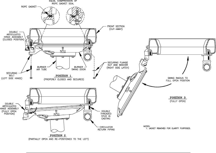
1.TO OPEN BURNER SWING DOOR (see Figures 11A and 11B).
Step 1. Loosen and remove right side latching hardware (5/16" flange nut and washer).
Step 2. Loosen and remove left side hinge hardware (5/16" x 3-1/2" lg. hex head flange bolt).
Step 3. The duel pivot articulated hinge allows right side of door to be pulled outward and rotated
to the left all in one motion. To do so, place your right hand under burner air tube and lift up slightly to help carry the weight of the door and burner. Use your left hand to grasp the door's left side hinge flange, pull outward to rotate the hinge, this motion will move the door outward and to the left approximately 3" (see Figure 11B, Position 2).
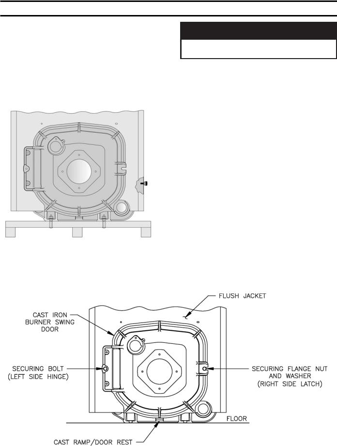
Figure 11A: Partial Front View - Burner Swing Door Mounted to Boiler - Fully Closed and Secured
26
27
Figure 11B: Top View - Burner Swing Door Mounted to Cast Iron Block Assembly (Jacket Removed for Clarity)
Step 4. From this position the door can be swung clear of the vertical circulator return piping to provide full access to the combustion chamber and burner head (see Figure 11B, Position 3).
2.Perform routine inspection, service or cleaning as necessary.
3.To close Burner Swing Door (see Figures 11A and 11B):
Step 1. From the fully open position, rotate Burner Swing Door toward the closed position. Make sure that the articulated hinge is rotated to the extreme left position to allow the door to clear the vertical circulator return piping as shown in Figure 11B, Position 2.
Step 2. Grasp the door's left side hinge flange in your left hand and place your right hand under the burner air tube to lift upward. Lift the door up unto the built-in cast ramp/door rest (protruding from the bottom of the front
section casting - see Figure 11A), while rotating the articulated hinge and door to the right and engaging the slot (on right side of door) unto the 5/16" stud protruding from the front section.
Step 3. Use one hand to help hold door in position by lifting up on rear burner housing or applying pressure directly to the door while re-installing the securing hardware with your opposite hand.
Always install right side latching hardware (5/16" flange nut and flat washer) first, then install left side hinge hardware (5/16" x 3- 1/2" lg. hex head flange bolt) second. Apply additional pressure while hand tightening the hardware as far as possible, then release the pressure.
NOTICE
When securing burner swing door make sure door is drawn-in equally on both sides.
Step 4. Use a hand wrench to tighten door hardware and always start with the right side flange
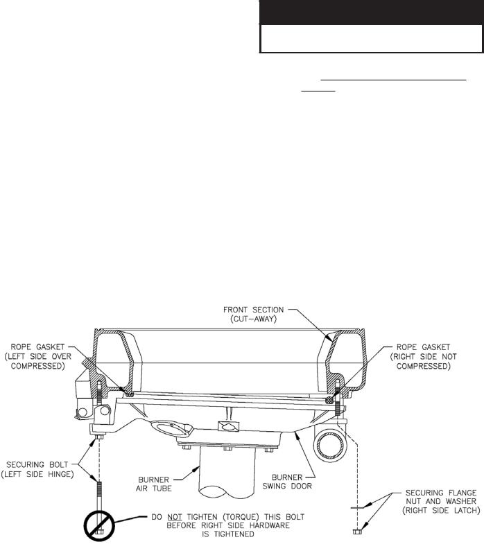
nut first. Use an alternating tightening method from right side flange nut to left side flange bolt to tighten door equally until sealed without applying excessive torque. Never tighten left side flange bolt first or tighten either piece of hardware 100% without using the alternating tightening method described above.
Failure to follow the prescribed procedure could cause thread damage to casting or a leak in the door seal. If left side flange bolt is tightened before right side flange nut, right side of door can not be drawn-in to provide an air tight seal, as shown in Figure 11C. Applying excessive torque will only cause thread damage.
Figure 11C: Top View - Burner Swing Door Fully Closed but Not Properly Secured or Sealed
28
E.INSPECT COMBUSTION CHAMBER TARGET WALL AND LINER, AND SWING DOOR GASKET.
1.Open burner swing door using procedure previously outlined in Paragraph D of this section.
2.Using a flashlight, inspect the rear target wall and liner. The target wall should be rigidly secured to the rear boiler section. The combustion chamber liner should be evenly distributed in the boiler chamber. If either is damaged, they must be replaced.
3.Inspect ceramic rope located on the swing door. The rope must be evenly distributed around the perimeter of the door groove and cannot bunch or overhang. There must not be a gap where the two ends of the rope meet. Repair or replace if the rope is damaged or if there is a gap between the ends.
F.INSPECT NOZZLE AND ELECTRODES / CHANGE FIRING RATE FOR BECKETT BURNERS. Refer to Section II, Paragraph J, No. 7, steps b through o for nozzle installation, electrode and head setting inspection.
Steam Boilers Only
Packaged V83 - V86 steam boilers are shipped with the lower (standard) firing rate nozzle installed.
Packaged V87 - V89 boilers are provided with one nozzle, installed in the burner, that provides the same firing rate as the water boiler of the same size.
Inspect the installed nozzle and assure that the nozzle is the correct size and type as specified in Table 6 of this manual.
Inspect and measure burner electrodes. Refer to Figure 27 of this manual for the proper electrode settings.
Close the burner swing door and securely seal the door to the boiler front section by reinstalling the hardware and securing the door using procedure previously outlined in Paragraph D of this section.
Water Boilers Only
Packaged V8 water boilers are shipped with the higher input oil nozzle installed in the burner.
A second oil nozzle for the lower (minimum) firing rate is shipped loose for the V83 - V86 models, attached to the burner. Select the proper oil nozzle for the installation. The lower (minimum) input nozzle will provide greater boiler efficiency. However, boiler output will be reduced. Refer to Table 1B for ratings. If the higher rate is desired, inspect the installed nozzle and assure that the nozzle is the correct size and type as specified in Table 6 of this manual.
If the lower (minimum) input is desired, remove the nozzle which was factory installed. Locate the lower (minimum) firing rate nozzle that is supplied loose. Confirm the nozzle is the proper size and type for the lower firing rate as specified in Table 6 of this manual. Install the proper nozzle in the burner nozzle adaptor.
G.INSPECT NOZZLE AND ELECTRODES / CHANGE FIRING RATE FOR CARLIN
102CRD BURNERS. Refer to Section II, Paragraph K, No. 7, steps b through d for nozzle installation, electrode and head setting inspection.
Follow instructions in Paragraphs A through E.
Steam or Water Boilers
Packaged V87 - V89 steam boilers are provided with one nozzle, installed in the burner, that provides the same firing rate as the water boiler of the same size.
Inspect the installed nozzle and assure that the nozzle is the correct size and type as specified in Table 6 of this manual.
H.INSPECT NOZZLE AND ELECTRODES / CHANGE FIRING RATE FOR CARLIN ELITE EZ BURNERS. Refer to Section II, Paragraph L, No. 7, steps a through c for nozzle installation, electrode and head setting inspection.
Follow instructions in Section III, Paragraphs A through E.
Steam Boilers Only
Packaged V83 - V86 steam boilers are shipped with the lower (standard) firing rate nozzle installed. Packaged V87 - V89 boilers are provided with one nozzle, installed in the burner, that provides the same firing rate as the water boiler of the same size. Inspect the installed nozzle and assure that the nozzle is the correct size and type as specified in Table 6.
Water Boilers Only
Packaged V8 water boilers are shipped with the higher input oil nozzle installed in the burner.
A second oil nozzle for the lower (minimum) firing rate is shipped loose for the V83 - V86 models, attached to the burner. Select the proper oil nozzle for the installation. The lower (minimum) input nozzle will provide greater boiler efficiency. However, boiler output will be reduced. Refer
to Table 1B For firing rates. If the higher rate is desired, inspect the installed nozzle and assure that the nozzle is the correct size and type as specified in Table 6.
29

If the lower (minimum) input is desired, remove the nozzle which was factory installed. Locate the lower (minimum) firing rate nozzle that is supplied loose. Confirm the nozzle is the proper size and type for the lower firing rate as specified in Table 6. Install the proper nozzle in the burner nozzle adaptor.
I.INSPECT NOZZLE AND ELECTRODES / CHANGE FIRING RATE FOR RIELLO
BURNERS. Refer to Section II, Paragraph M, No. 7, steps a through g for nozzle installation, electrode and head setting inspection.
Steam Boilers Only
Packaged V83 - V86 steam boilers are shipped with the lower (standard) firing rate nozzle installed. Packaged V87 - V89 boilers are provided with one nozzle, installed in the burner, that provides the same firing rate as the water boiler of the same size. Inspect the installed nozzle and assure that the nozzle is the correct size and type as specified in Table 6 of this supplement.
Water Boilers Only
Packaged V8 water boilers are shipped with the higher input oil nozzle installed in the burner.
A second oil nozzle for the lower (minimum) firing rate is shipped loose for the V83 - V86 models, attached to the burner. Select the proper oil nozzle for the installation. The lower (minimum) input nozzle will provide greater boiler efficiency. However, boiler output will be reduced. Refer
to Table 1B for firing rates. If the higher rate is desired, inspect the installed nozzle and assure that the nozzle is the correct size and type as specified in Table 6.
If the lower (minimum) input is desired, remove the nozzle which was factory installed. Locate the lower (minimum) firing rate nozzle that is supplied loose. Confirm the nozzle is the proper size and type for the lower firing rate as specified in Table 6. Install the proper nozzle in the burner nozzle adaptor.
J.INSTALL SAFETY OR RELIEF VALVE IN TAPPING "M".
Use ¾" NPT x 8" nipple and/or ¾" NPT coupling included in trim bag. Safety or Relief Valve must be installed with spindle in vertical position. Pipe discharge as shown in Figures 13A, 13B, 13C and 14. Installation of the safety or relief valve must be consistent with ANSI/ASME Boiler and Pressure Vessel Code, Section IV.
WARNING
Safety or relief valve discharge piping must be piped near floor to eliminate potential of severe burns. Do not pipe in any area
where freezing could occur. Do not install any shut-off valves, plugs or caps.
K.PACKAGED BOILERS WITH PROBE STYLE LWCO. Install Limit in Tapping "A" using ¾" NPT x 2" nipple, ¾" NPT elbow, ¾" NPT x ¼" NPT bushing, and syphon included in trim bag. See Figure 9.
1.Do not tighten the limit by holding the case; apply a wrench to the brass hex below the case.
2.Connect wiring harness from Low Water Cut-Off to steam pressure limit.
3.Level an L404A pressure limit by carefully bending the syphon until the limit's leveling indicator hangs freely with its pointer directly over the index mark inside the back of the case.
NOTICE
L404A Pressure Limits contain mercury in a sealed tube. Do not place limit in the trash at the end of its useful life.
If this limit is replacing a limit that contains mercury in a sealed tube, do not place your old limit in the trash.
Contact your local waste management authority for instructions regarding recycling and the proper disposal of this limit, or of an old limit containing mercury in a sealed tube.
If you have questions, call Honeywell Inc. at
1-800-468-1502.
4.An L404F pressure limit does not require leveling.
30
 Loading...