


Black Box ACX288-CTL, ACXIO8-C, ACXSFPC, ACX288-PS, ACXSFPS User Manual
...
|
|
ACX048 |
ACXIO8-C |
ACX288-CTL |
ACX080-PS |
|
|
ACX080 |
ACXIO8-SM |
ACXSFPC |
ACX160-PS |
|
|
ACX160 |
ACXIO8-SPF |
ACXSFPS |
ACX288-PS |
|
|
ACX288 |
|
|
|
|
|
|
|
|
|
|
|
|
|
|
|
|
|
|
|
|
|
ServSwitch™ DKM FX
Provides flexible and super-fast crosspoint switching of Full HD video in KVM enterprises.
Customer |
Order toll-free in the U.S.: Call 877-877-BBOX (outside U.S. call 724-746-5500) |
Support |
FREE technical support 24 hours a day, 7 days a week: Call 724-746-5500 or fax |
Information |
724-746-0746 • Mailing address: Black Box Corporation, 1000 Park Drive, Lawrence, |
|
PA 15055-1018 • Web site: www.blackbox.com • E-mail: info@blackbox.com |
|
|

Trademarks Used in this Manual
Trademarks Used in this Manual
Black Box and the Double Diamond logo are registered trademarks, and ServSwitch is a trademark, of BB Technologies, Inc.
Mac is a registered trademark of Apple Computer, Inc.
IBM is a registered trademark of International Business Machines Corporation.
Java is a registered trademark of Oracle Corporation.
TOSLINK is a registered trademark of Toshiba Corporation.
Any other trademarks mentioned in this manual are acknowledged to be the property of the trademark owners.
Page 2 |
724-746-5500 | blackbox.com |

FCC and IC RFI Statements/NOM Statement
FEDERAL COMMUNICATIONS COMMISSION AND
INDUSTRY CANADA RADIO FREQUENCY INTERFERENCE STATEMENTS
This equipment generates, uses, and can radiate radio-frequency energy, and if not installed and used properly, that is, in strict accordance with the manufacturer’s instructions, may cause interference to radio communication.
It has been tested and found to comply with the limits for a Class A computing device in accordance with the specifications in Subpart B of Part 15 of FCC rules, which are designed to provide reasonable protection against such interference when the equipment is operated in a commercial environment. Operation of this equipment in a residential area is likely to cause interference, in which case the user at his own expense will be required to take whatever measures may be necessary to correct the interference.
Changes or modifications not expressly approved by the party responsible for compliance could void the user’s authority to operate the equipment.
This digital apparatus does not exceed the Class A limits for radio noise emission from digital apparatus set out in the Radio Interference Regulation of Industry Canada.
Le présent appareil numérique n’émet pas de bruits radioélectriques dépassant les limites applicables aux appareils numériques de la classe A prescrites dans le Règlement sur le brouillage radioélectrique publié par Industrie Canada.
Normas Oficiales Mexicanas (NOM)
Electrical Safety Statement
INSTRUCCIONES DE SEGURIDAD
1.Todas las instrucciones de seguridad y operación deberán ser leídas antes de que el aparato eléctrico sea operado.
2.Las instrucciones de seguridad y operación deberán ser guardadas para referencia futura.
3.Todas las advertencias en el aparato eléctrico y en sus instrucciones de operación deben ser respetadas.
724-746-5500 | blackbox.com |
Page 3 |

NOM Statement
4.Todas las instrucciones de operación y uso deben ser seguidas.
5.El aparato eléctrico no deberá ser usado cerca del agua—por ejemplo, cerca de la tina de baño, lavabo, sótano mojado o cerca de una alberca, etc.
6.El aparato eléctrico debe ser usado únicamente con carritos o pedestales que sean recomendados por el fabricante.
7.El aparato eléctrico debe ser montado a la pared o al techo sólo como sea recomendado por el fabricante.
8.Servicio—El usuario no debe intentar dar servicio al equipo eléctrico más allá lo descrito en las instrucciones de operación. Todo otro servicio deberá ser referido a personal de servicio calificado.
9.El aparato eléctrico debe ser situado de tal manera que su posición no interfiera su uso. La colocación del aparato eléctrico sobre una cama, sofá, alfombra o superficie similar puede bloquea la ventilación, no se debe colocar en libreros o gabinetes que impidan el flujo de aire por los orificios de ventilación.
10.El equipo eléctrico deber ser situado fuera del alcance de fuentes de calor como radiadores, registros de calor, estufas u otros aparatos (incluyendo amplificadores) que producen calor.
11.El aparato eléctrico deberá ser connectado a una fuente de poder sólo del tipo descrito en el instructivo de operación, o como se indique en el aparato.
12.Precaución debe ser tomada de tal manera que la tierra fisica y la polarización del equipo no sea eliminada.
13.Los cables de la fuente de poder deben ser guiados de tal manera que no sean pisados ni pellizcados por objetos colocados sobre o contra ellos, poniendo particular atención a los contactos y receptáculos donde salen del aparato.
14.El equipo eléctrico debe ser limpiado únicamente de acuerdo a las recomendaciones del fabricante.
15.En caso de existir, una antena externa deberá ser localizada lejos de las lineas de energia.
16.El cable de corriente deberá ser desconectado del cuando el equipo no sea usado por un largo periodo de tiempo.
Page 4 |
724-746-5500 | blackbox.com |

NOM Statement
17.Cuidado debe ser tomado de tal manera que objectos liquidos no sean derramados sobre la cubierta u orificios de ventilación.
18.Servicio por personal calificado deberá ser provisto cuando:
A:El cable de poder o el contacto ha sido dañado; u
B:Objectos han caído o líquido ha sido derramado dentro del aparato; o
C:El aparato ha sido expuesto a la lluvia; o
D:El aparato parece no operar normalmente o muestra un cambio en su desempeño; o
E:El aparato ha sido tirado o su cubierta ha sido dañada.
724-746-5500 | blackbox.com |
Page 5 |

Safety Instructions
Safety Instructions
For reliable and safe long-term operation of your ServSwitch DKM FX, follow these guidelines:
Installation
•Only use in dry, indoor environments.
•The ServSwitch DKM FX and the power supply units can get warm. Don’t put them in an enclosed space without any airflow.
•Do not obscure ventilation holes.
•Only use power supplies originally supplied with the product or manufacturerapproved replacements. Do not use a power supply if it appears to be defective or has a damaged case.
•Connect all power supplies to grounded outlets. In each case, make sure that the ground connection is maintained from the outlet socket to the power supply’s AC power input.
•Do not connect the link interface to any other equipment, particularly network or telecommunications equipment.
•Take any required ESD precautions.
Repair
•Do not attempt to open or repair a power supply unit.
•Do not attempt to open or repair the ServSwitch DKM FX. There are no user-serviceable parts inside.
•Contact Black Box Technical Support at 724-746-5500 or info@blackbox.com if there is a fault.
Page 6 |
724-746-5500 | blackbox.com |

|
|
|
|
Table of Contents |
|
|
|
||
Chapter |
|
Page |
||
1. |
Specifications.......................................................................................... |
10 |
||
|
1.1 |
Interfaces......................................................................................... |
10 |
|
|
|
1.1.1 |
DVI-D Single Link................................................................... |
10 |
|
|
1.1.2 |
USB HID................................................................................. |
10 |
|
|
1.1.3 |
RJ-45 (Network).................................................................... |
10 |
|
|
1.1.4 |
RS-232 (Serial)....................................................................... |
11 |
|
|
1.1.5 |
RJ-45 (Interconnect).............................................................. |
11 |
|
|
1.1.6 |
Fiber SFP Type LC (Interconnect)............................................ |
11 |
|
|
1.1.7 |
SDI (Interconnect).................................................................. |
11 |
|
1.2 |
Interconnect Cable........................................................................... |
11 |
|
|
|
1.2.1 |
CATx...................................................................................... |
11 |
|
|
1.2.2 |
Fiber....................................................................................... |
12 |
|
|
1.2.3 |
Coaxial................................................................................... |
13 |
|
1.3 |
Supported Peripherals...................................................................... |
14 |
|
|
1.4 |
Connector Pinouts........................................................................... |
14 |
|
|
|
1.4.1 |
CPU Board............................................................................. |
14 |
|
|
1.4.2 |
I/O Board CATx...................................................................... |
16 |
|
|
1.4.3 |
I/O Board SFP......................................................................... |
16 |
|
|
1.4.4 |
I/O Board SDI......................................................................... |
16 |
|
1.5 |
Power Supply................................................................................... |
17 |
|
|
1.6 |
Environmental Conditions................................................................ |
17 |
|
|
1.7 |
Size......... |
.......................................................................................... |
17 |
|
1.8 |
Shipping Weight.............................................................................. |
17 |
|
2. |
Overview.................................................................................................. |
|
18 |
|
|
2.1 |
Description....................................................................................... |
18 |
|
|
|
2.1.1 |
Application............................................................................ |
18 |
|
|
2.1.2 |
Access Options...................................................................... |
18 |
|
2.2 |
System Overview.............................................................................. |
19 |
|
|
2.3 |
Available Products........................................................................... |
20 |
|
|
2.4 |
What’s Included.............................................................................. |
20 |
|
|
2.5 |
Device Views.................................................................................... |
21 |
|
|
|
2.5.1 |
ServSwitch DKM FX 288-Port................................................ |
21 |
|
|
2.5.2 |
ServSwitch DKM FX 160-Port............................................... |
22 |
|
|
2.5.3 |
ServSwitch DKM FX 80-Port................................................. |
23 |
|
|
2.5.4 |
ServSwitch DKM FX 48-Port.................................................. |
24 |
724-746-5500 | blackbox.com |
Page 7 |

Table of Contents
Chapter |
|
Page |
||
|
2.6 |
Diagnostics and Status..................................................................... |
24 |
|
|
|
2.6.1 |
Status LEDs............................................................................ |
24 |
|
|
2.6.2 |
Port Status............................................................................ |
30 |
|
|
2.6.3 |
Network Status..................................................................... |
33 |
|
|
2.6.4 |
Firmware Status.................................................................... |
35 |
|
2.7 |
Trace Function.................................................................................. |
37 |
|
3. |
Installation |
............................................................................................. |
39 |
|
|
3.1 |
System Setup.................................................................................. |
39 |
|
|
3.2 |
Example Applications...................................................................... |
40 |
|
|
|
3.2.1 |
KVM Matrix.......................................................................... |
40 |
|
|
3.2.2 |
Video Matrix.......................................................................... |
41 |
|
|
3.2.3 |
Parallel Operation (Stacking)................................................. |
42 |
|
|
3.2.4 |
Cascading............................................................................. |
43 |
4. |
Configuration......................................................................................... |
45 |
||
|
4.1 |
Command Mode............................................................................ |
45 |
|
|
4.2 |
Control Options.............................................................................. |
46 |
|
|
|
4.2.1 |
Control via OSD.................................................................... |
46 |
|
|
4.2.2 |
Control via Java Tool............................................................. |
50 |
|
|
4.2.3 |
Control via Serial Interface.................................................... |
56 |
|
4.3 |
Assignment..................................................................................... |
56 |
|
|
|
4.3.1 |
Virtual CPU to Real CPU....................................................... |
56 |
|
|
4.3.2 |
Real Console to Virtual Console............................................ |
58 |
|
4.4 |
System Settings................................................................................ |
59 |
|
|
|
4.4.1 |
System Data........................................................................... |
59 |
|
|
4.4.2 |
Automatic ID........................................................................ |
62 |
|
|
4.4.3 |
Access................................................................................... |
64 |
|
|
4.4.4 |
Switch................................................................................... |
67 |
|
|
4.4.5 |
Network................................................................................. |
70 |
|
|
4.4.6 |
Date and Time...................................................................... |
72 |
|
4.5 User Settings..................................................................................... |
74 |
||
|
4.6 |
Extender Settings............................................................................ |
77 |
|
|
4.7 |
CPU Settings.................................................................................... |
81 |
|
|
4.8 |
Console Settings............................................................................. |
84 |
|
|
|
4.8.1 |
CON Devices......................................................................... |
84 |
|
|
4.8.2 |
Mouse and Keyboard........................................................... |
88 |
|
4.9 |
Saving and Loading of Configurations............................................ |
90 |
|
|
|
4.9.1 |
Active Configuration............................................................. |
90 |
Page 8 |
724-746-5500 | blackbox.com |

|
|
|
|
Table of Contents |
|
|
|
||
Chapter |
|
Page |
||
|
|
4.9.2 |
Saving of Configurations (Internal)......................................... |
91 |
|
|
4.9.3 |
Loading of Configurations (Internal)...................................... |
93 |
|
|
4.9.4 |
Saving of Configurations (External)....................................... |
95 |
|
|
4.9.5 Loading of Configurations (External).................................... |
96 |
|
|
4.10 |
Export and Import Options............................................................ |
97 |
|
|
|
4.10.1 Export Options...................................................................... |
97 |
|
|
|
4.10.2 Import Options..................................................................... |
98 |
|
|
4.11 Firmware Update............................................................................ |
99 |
||
5. |
Operation |
......................................................................................... |
101 |
|
|
5.1 |
Operation via Hotkeys.................................................................. |
101 |
|
|
|
5.1.1 |
Direct Switching............................................................... |
101 |
|
|
5.1.2 |
Scan Mode....................................................................... |
102 |
|
|
5.1.3 Addressing of Master and Slave....................................... |
102 |
|
|
|
5.1.4 |
Function Keys <F1>–<F12>............................................. |
103 |
|
5.2 |
KVM Switching............................................................................ |
103 |
|
|
5.3 |
Serial Interface............................................................................. |
106 |
|
|
5.4 Power On and Power Down Functions........................................ |
107 |
||
|
|
5.4.1 |
Restart.............................................................................. |
107 |
|
|
5.4.2 |
Reset................................................................................ |
107 |
|
|
5.4.3 |
Power Down.................................................................... |
107 |
6. |
Serial Control....................................................................................... |
108 |
||
7. |
Troubleshooting.................................................................................... |
120 |
||
|
7.1 |
External Failure............................................................................... |
120 |
|
|
7.2 |
Video Interference.......................................................................... |
120 |
|
|
7.3 |
Fans Malfunction........................................................................... |
120 |
|
|
7.4 |
Power Supply Units Malfunction.................................................... |
121 |
|
|
7.5 |
Network Error................................................................................ |
121 |
|
|
7.6 |
ServSwitch DKM FX Failure............................................................ |
121 |
|
|
7.7 |
Blank Screen.................................................................................. |
122 |
|
|
7.8 |
Contacting Black Box..................................................................... |
122 |
|
|
7.9 |
Shipping and Packaging................................................................. |
123 |
|
Appendix. Glossary...................................................................................... |
124 |
|||
724-746-5500 | blackbox.com |
Page 9 |

Chapter 1: Specifications
1. Specifications
1.1 Interfaces
1.1.1 DVI-D Single Link
The video interface supports the DVI-D protocol. All signals that comply with DVI-D single-link standard can be transmitted. This includes, for example, monitor resolutions such as 1920 x 1200 @ 60 Hz, Full HD (1080p), or 2K HD (up to 2048 x 1152). Data rate is limited to 165 MPixel/s.
1.1.2 USB HID
Devices with USB HID interface support a maximum of two devices with
USB HID protocol. Each USB HID port provides a maximum current of 100 mA.
Keyboard
Compatible with most USB keyboards. Certain keyboards with additional functions may require custom firmware to operate. Keyboards with an integral USB Hub (Mac® keyboards, for example) are also supported.
Mouse
Compatible with most 2-button, 3-button, and scroll mice.
Other USB HID devices
The proprietary USB emulation also supports certain other USB HID devices, such as specific touchscreens, graphics tablets, bar-code scanners, or special keyboards. Support cannot be guaranteed, however, for every USB HID device.
NOTE: Only two USB HID devices are supported concurrently, such as keyboard and mouse or keyboard and touchscreen. A hub is allowed, but it does not increase the number of HID devices allowed.
To support other USB “non-HID” devices, such as scanners, Web cams or memory devices, choose our devices with transparent USB support.
1.1.3 RJ-45 (Network)
CATx device communication requires a 1000BASE-T connection. Pin the cable according to EIA/TIA-568-B (1000BASE-T) standard with RJ-45 connectors at both ends. All four wire pairs are used in both directions. The cabling is suitable for full-duplex operation. For the cable connection to a source (computer, CPU), use a cross-pinned network cable.
Page 10 |
724-746-5500 | blackbox.com |
Chapter 1: Specifications
1.1.4 RS-232 (Serial)
The communication takes place with a transmission speed of up to 115.2 kbps, regardless of the file format. The transmission takes place with eight data bits and a stop bit, but without a parity bit. Limited hardware handshake (DSR) is possible.
1.1.5 RJ-45 (Interconnect)
CATx device communication requires a 1000BASE-T connection.
Connector wiring must comply with EIA/TIA-568-B (1000BASE-T), with RJ-45 connectors at both ends. All four wire pairs are used.
1.1.6 Fiber SFP Type LC (Interconnect)
Fiber device communication is performed via Gigabit SFPs connected to suitable fibers fitted with LC connectors (see Section 1.2.2).
NOTE: The correct function of the device can only be guaranteed with SFPs provided by Black Box.
CAUTION: SFP modules can be damaged by electrostatic discharge (ESD). Follow ESD handling precautions.
1.1.7 SDI (Interconnect)
SDI device communication requires a mini coax connection with mini BNC connectors or 3G SFPs with transmission speeds of 0.360 Gbps (SD-SDI, SMPTE 259M), 1.485 Gbps (HD-SDI, SMPTE 292M), and 2.70 Gbps (3G SDI).
1.2 Interconnect Cable 1.2.1 CATx
NOTE: A point-to-point connection is required. Operation with several patch fields is possible. Routing over an active network component, such as an Ethernet hub, router, or ServSwitch DKM FX, is not allowed.
•Avoid routing CATx cables along power cables.
•If the site has three-phase AC power, make sure that the CPU Unit and
CON Unit are on the same phase.
NOTE: To maintain regulatory EMC compliance, use correctly installed shielded CATx cable throughout the interconnection link.
NOTE: To maintain regulatory EMC compliance, all CATx cables need to carry ferrites on both cable ends close to the device.
Type of Interconnect Cable
The ServSwitch DKM FX requires interconnect cabling specified for Gigabit Ethernet (1000BASE-T). Use solid-core (24 AWG), shielded, CAT5e (or better) cable.
724-746-5500 | blackbox.com |
Page 11 |

Chapter 1: Specifications
Table 1-1. CATx interconnect cable.
Cable Type |
Description |
|
|
This S/UTP (CAT5e) cable confoms to EIA/TIA-568-B. CATx solid-core 24 AWG cable Uses four pairs of 24 AWG wires. Connects according
to EIA/TIA-568-B (1000BASE-T).
This S/UTP (CAT5e) cable confoms to EIA/TIA-568-B. CATx solid-core 26/8 AWG cable Uses four pairs of 26/8 AWG wires. Connects according
to EIA/TIA-568-B (1000BASE-T).
NOTE: You can use use type 26/8 AWG flexible cables (patch cables), but the maximum possible extension distance is cut in half.
Table 1-2. Maximum acceptable cable length.
Cable Type |
Distance |
|
|
CATx 24 AWG installation cable |
400 ft. (140 m) |
|
|
CATx 26/8 AWG patch cable |
200 ft. (70 m) |
|
|
1.2.2 Fiber
NOTE: A point-to-point connection is necessary. Operation with multiple patch panels is allowed. Routing over active network components, such as Ethernet hubs, ServSwitch DKM FXes, or routers, is not allowed.
Type of Interconnect Cable
|
Table 1-3. Fiber interconnect cable. |
|
|
|
|
Cable Type |
Description |
|
|
|
|
Single-mode, 9-µm |
• Two fibers, 9-µm |
|
• In-house patch cable (EFN092) |
||
|
||
|
|
|
Multimode 50-µm |
• Two fibers, 50-µm |
|
• In-house patch cable (EFN6020) |
||
|
||
|
|
|
Multimode 62.5-µm |
• Two fibers, 62.5-µm |
|
• In-house patch cable (EFN116-LCLC) |
||
|
||
|
|
NOTE: Only use single-mode cables for fiber connections that are based on 3G SFPs.
Page 12 |
724-746-5500 | blackbox.com |

Chapter 1: Specifications
Table 1-4. Maximum acceptable fiber cable length.
Cable Type |
Distance |
|
|
Single-mode 9-µm |
32,800 ft. (10,000 m) |
|
|
Multimode 50-µm (OM3) |
3280 ft. (1000 m) |
|
|
Multimode 50-µm |
1300 ft. (400 m) |
|
|
Multimode 62.5µm |
650 ft. (200 m) |
|
|
NOTE: If you use single-mode SFPs with multimode fiber optic cable, you can double the maximum acceptable cable length.
Type of Connector
The fiber cable uses LC connectors.
1.2.3 Coaxial
NOTE: A point-to-point connection is necessary.
Table 1-5. Coaxial interconnect cable.
Cable Type |
Description |
|
|
|
|
Mini coaxial cable, 18 AWG |
RG-6 |
|
Impedance: 75 ohms |
||
|
||
|
|
Table 1-6. Maximum acceptable coaxial cable length.
Bandwidth |
Distance |
|
|
0.270 Gbps |
1312 ft. (400 m) |
|
|
1.485 Gbps |
459 ft. (140 m) |
|
|
2.970 Gbps |
394 ft. (120 m) |
|
|
Type of Connector
The coaxial cable uses mini BNC connectors.
724-746-5500 | blackbox.com |
Page 13 |
Chapter 1: Specifications
1.3 Supported Peripherals
You can use the KVM extenders described in Tables 1-7 and 1-8 with the ServSwitch DKM FX:
Table 1-7. KVM extender with CATx connection.
Product Code |
Description |
|
|
ACX1T-11-C |
KVM CPU unit, single-head, 2x USB HID |
|
|
ACX1R-11-C |
KVM CON unit, single-head, 2x USB HID |
|
|
ACX1T-11V-C |
KVM CPU unit, single-head, DVI-I input (VGA), 2x USB HID |
|
|
ACX1R-11V-C |
KVM CON unit, single-head, IR receiver, 2x USB HID |
|
|
Table 1-8. KVM extender with fiber (single-mode) connection.
Product Code |
Description |
|
|
ACX1T-11-SM |
KVM CPU unit, single-head, 2x USB HID |
|
|
ACX1R-11-SM |
KVM CON unit, single-head, 2x USB HID |
|
|
ACX1T-11V-SM |
KVM CPU unit, single-head, DVI-I input (VGA), 2x USB HID |
|
|
ACX1R-11V-SM |
KVM CON unit, single-head, IR receiver, 2x USB HID |
|
|
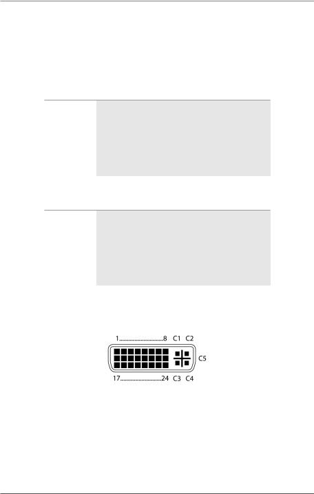
1.4 Connector Pinouts
1.4.1 CPU Board
Figure 1-1. DVI-D single-link connector.
Page 14 |
724-746-5500 | blackbox.com |
Chapter 1: Specifications
Table 1-9. DVI-D single-link connector pinout.
Pin |
Signal |
Pin |
Signal |
Pin |
Signal |
|
|
|
|
|
|
1 |
T.M.D.S. data 2- |
9 |
T.M.D.S. data 1- |
17 |
T.M.D.S. data 0- |
|
|
|
|
|
|
2 |
T.M.D.S. data 2+ |
10 |
T.M.D.S. data 1+ |
18 |
T.M.D.S. data 0+ |
|
|
|
|
|
|
3 |
T.M.D.S. data 2 GND |
11 |
T.M.D.S. data 1 GND |
19 |
T.M.D.S. data 0 GND |
|
|
|
|
|
|
4 |
Not connnected |
12 |
Not connected |
20 |
Not connected |
|
|
|
|
|
|
5 |
Not connected |
13 |
Not connected |
21 |
Not connected |
|
|
|
|
|
|
6 |
DDC input (SCL) |
14 |
+5 VDC high impedance |
22 |
T.M.D.S. GND |
|
|
|
|
|
|
7 |
DDC output (SDA) |
15 |
GND |
23 |
T.M.D.S. clock+ |
|
|
|
|
|
|
8 |
Internal use |
16 |
Hot plug recognition |
24 |
T.M.D.S. clock- |
|
|
|
|
|
|
C1 |
Internal use |
— |
— |
C3 |
Internal use |
|
|
|
|
|
|
C2 |
Not connected |
C5 |
GND |
C4 |
Internal use |
|
|
|
|
|
|
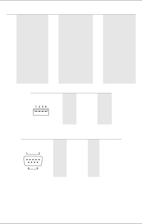
Table 1-10. USB Type A connector.
Picture |
Pin |
Signal |
Color |
|
|
|
|
|
1 |
VCC (+5 VDC) |
Red |
|
|
|
|
|
2 |
Data - |
White |
|
|
|
|
|
3 |
Data + |
Green |
|
|
|
|
|
4 |
GND |
Black |
|
|
|
|
Table 1-11. DB9 connector.
Picture |
Pin |
Signal |
Color |
Signal |
|
|
|
|
|
|
1 |
Not connected |
6 |
DTR |
|
|
|
|
|
|
2 |
CTS |
7 |
TxD |
|
|
|
|
|
|
3 |
RTS |
8 |
RxD |
|
|
|
|
|
|
4 |
DSR |
9 |
Not connected |
|
|
|
|
|
|
5 |
GND |
— |
— |
|
|
|
|
|
724-746-5500 | blackbox.com |
Page 15 |
Chapter 1: Specifications
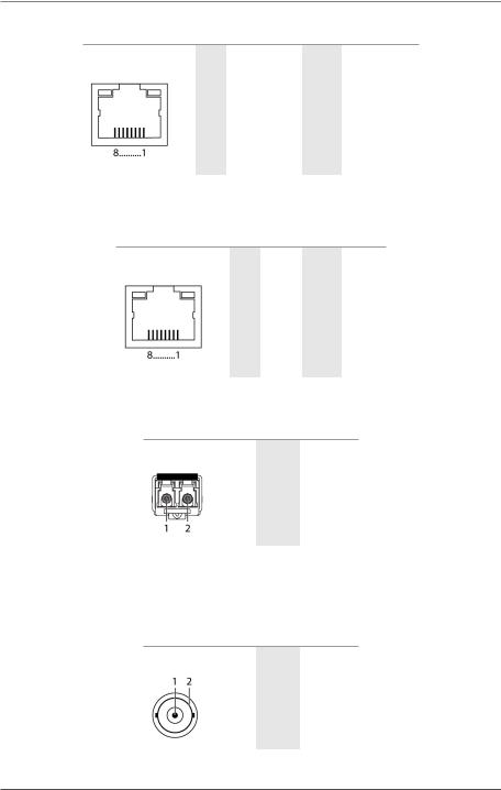
Table 1-12. RJ-45 connector.
Picture |
Pin |
Signal |
Color |
Signal |
|
|
|
|
|
|
1 |
D1+ |
5 |
Not connected |
|
|
|
|
|
|
2 |
D1- |
6 |
D2- |
|
|
|
|
|
|
3 |
D2+ |
7 |
Not connected |
|
|
|
|
|
|
4 |
Not connected |
8 |
Not connected |
|
|
|
|
|
1.4.2 I/O Board CATx
Table 1-13. RJ-45 CATx connector.
Picture |
Pin |
Signal |
Color |
Signal |
|
|
|
|
|
|
1 |
D1+ |
5 |
D3- |
|
|
|
|
|
|
2 |
D1- |
6 |
D2- |
|
|
|
|
|
|
3 |
D2+ |
7 |
D4+ |
|
|
|
|
|
|
4 |
D3+ |
8 |
D4- |
|
|
|
|
|
1.4.3 I/O Board SFP
Table 1-14. RJ-45 connector.
Picture |
Diode |
Signal |
|
|
|
|
1 |
Data OUT |
|
|
|
|
2 |
Data IN |
|
|
|
1.4.4 I/O Board SDI
Table 1-15. RJ-45 connector.
Picture |
Pin |
Signal |
|
|
|
|
1 |
Data In |
|
|
|
|
2 |
GND |
|
|
|
Page 16 |
724-746-5500 | blackbox.com |

Chapter 1: Specifications
1.5 Power Supply
Power — All models: Voltage: 100–240 VAC, 50–60 Hz; ACX288, ACX288-PS: 202 W max. without I/O boards; ACX160, ACX160-PS: 188 W max. without I/O boards; ACX080, ACX080-PS: 99 W max. without I/O boards; ACX048: 94 W max. without I/O boards;
I/O boards (ACXI08-C, ACXI08-SM, ACXI08-SPF): 13 W max.
1.6 Environmental Conditions
Temperature Tolerance — +41 to +113° F (+5 to +45° C)
Storage Temperature — -13 to +140° F (-25 to +60° C)
Relative Humidity — Max. 80%, non-condensing
1.7 Size
Size — ACX288: 19"H x 22.8"W x 12"D (48.3 x 57.8 x 33 cm), Shipping box: 25.6"H x 26.8"W x 29.9"D (65 x 68 x 76 cm);
ACX160: 19"H x 15.8"W x 12"D (48.3 x 40 x 33 cm), Shipping box: 25.6"H x 26.8"W x 12"D (65 x 68 x 54 cm);
ACX080: 19"H x 7"W x 9.1"D (64 x 57 x 36 cm),
Shipping box: 25.2"H x 22.4"W x 21.3"D (64 x 57 x 36 cm); ACX048: 19"H x 5.3"W x 9.1"D,
Shipping box: 25.2" x 22.4"W x 12.4"D (64 x 57 x 23.1 cm)
1.8 Shipping Weight
Weight — ACX288: 76.2 lb (34.6 kg) fully equipped, Shipping box: 90.6 lb. (41.1 kg);
ACX160: 60 lb. (26.3 kg) fully equipped, Shipping box: 69.9 lb. (31.7 kg);
ACX080: 24.5 lb. (11.1 kg) fully equipped, Shipping box: 34.4 lb. (15.6 kg);
ACX048: 19.6 lb. (8.9 kg), Shipping box: 26.7 lb. (12.1 kg)
724-746-5500 | blackbox.com |
Page 17 |
Chapter 2: Overview
2. Overview
2.1 Description
2.1.1 Application
The ServSwitch DKM FX is used to establish connections from consoles (monitor, keyboard, mouse, and other peripheral devices) to various sources (computer, CPU).
In a maximum configuration, up to 288 independent ports can be defined and switched either as a console or a CPU.
The ServSwitch DKM FX is mainly specified for the use with extenders that are able to transmit video, KVM, and USB 2.0 signals. You can also use it as a video matrix.
For the connection between the ServSwitch DKM FX and the peripheral devices, such as KVM extenders or video sources, you can use CATx, fiber, or coaxial cables.
The ServSwitch DKM FX serves as a repeater. You can place it up to 6.2 miles (10 km) from the consoles and 6.2 miles (10 km) from the sources.
2.1.2 Access Options
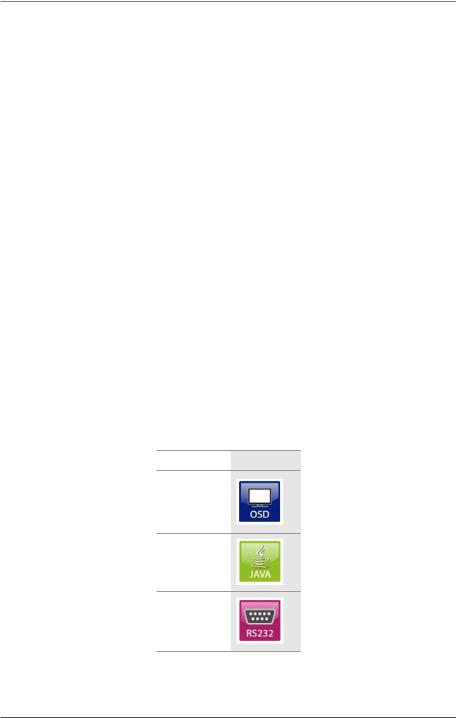
You have the following options to access the ServSwitch DKM FX for configuration and operation:
Table 2-1. Access options.
Access option Symbol
OSD
Java tool
Serial interface
Page 18 |
724-746-5500 | blackbox.com |
Chapter 2: Overview
2.2 System Overview
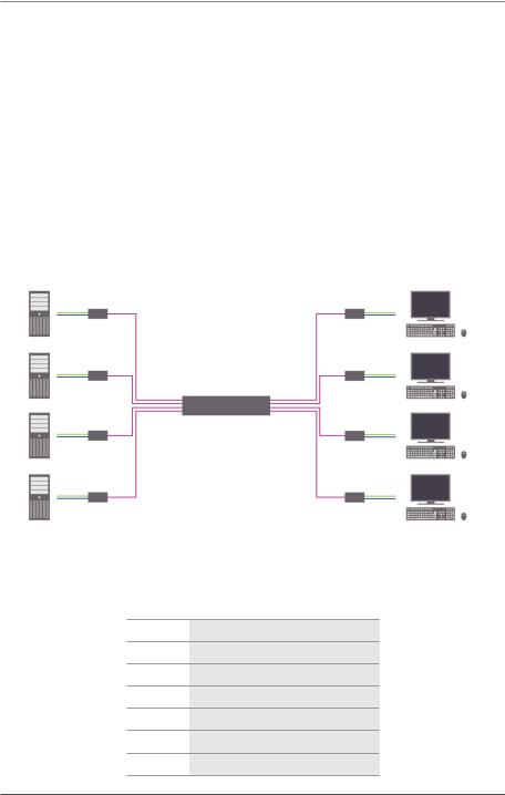
A ServSwitch DKM FX system consists of a ServSwitch DKM FX and, for KVM applications, one or more CPU units/CON units. The ServSwitch DKM FX is connected to the CPU units/CON units by interconnect cables or is connected directly to the video devices when used as a video matrix.
The CPU units connect directly to the sources (computer, CPU), using the included cables.
Monitor(s), keyboard, and mouse connect to the CON units.
The ServSwitch DKM FX and the CPU units/CON units communicate over CATx, fiber, or coaxial interconnect cables.
Figure 2-1 shows the system overview. Table 2-2 describes its components.
|
|
|
|
|
|
|
|
|
|
|
|
|
|
|
|
|
|
|
|
|
|
|
|
|
|
|
|
|
|
|
|
|
|
|
|
|
|
|
|
|
|
|
|
|
|
|
|
|
|
|
|
|
|
|
|
1 |
2 |
3 |
4 |
3 |
5 |
6 |
|||||||
Figure 2-1. System overview.
Table 2-2. System components.
Number Component
1Source (computer, CPU)
2CPU units
3Interconnect cable
4ServSwitch DKM FX
5CON units
6Console (monitor, keyboard, mouse)
724-746-5500 | blackbox.com |
Page 19 |

Chapter 2: Overview
See Section 3.2 for installation examples.
2.3 Available Products
|
Table 2-3. Available products. |
|
|
Number |
Description |
|
|
ServSwitch DKM FX |
|
|
|
ACX048 |
ServSwitch DKM FX 48-port with control card and power supply |
|
|
ACX080 |
ServSwitch DKM FX 80-port with control card and power supply |
|
|
ACX160 |
ServSwitch DKM FX 160-port with control card and power supply |
|
|
ACX288 |
ServSwitch DKM FX 288-port with control card and power supply |
|
|
Accessories |
|
|
|
ACXIO8-C |
8-port CATx input/output (I/O) module |
|
|
ACXIO8-SM |
8-port single-mode fiber input/output (I/O) module |
|
|
ACXIO8-SFP |
8-port single-mode fiber SFP input/output (I/O) module |
|
|
ACX288-CTL |
ServSwitch DKM FX controller card |
|
|
ACXSFPC |
CATx SFP module |
|
|
ACXSFPS |
Single-mode fiber SFP module |
|
|
ACX080-PS |
Power supply for ACX048 and ACX080 |
|
|
ACX160-PS |
Power supply for ACX160 |
|
|
ACX288-PS |
Power supply for ACX288 |
|
|
ACX080-FAN |
Tray for 48/80 port console |
|
|
ACX288-FAN |
Tray for 160/288 port console |
|
|
2.4 What’s Included
Your package should contain the following items. If anything is missing or damaged, contact Black Box Technical Support at 724-746-5500
or info@blackbox.com.
•(1) ServSwitch DKM FX (ACX048, ACX080, ACX160, or ACX288)
•(1) power cord per built-in power supply unit
•(1) DKM FX controller card
•(1) serial control cable
•(1) set of mounting accessories
•This users’ manual in PDF format and Java tool on CD-ROM
Page 20 |
724-746-5500 | blackbox.com |

Chapter 2: Overview
• (1) cross-wired CATx network cable
2.5 Device Views
In Sections 2.5.1 through 2.5.5, Figures 2-2 through 2-5 illustrate the ServSwitch DKM FX chassis models. Tables 2-4 through 2-8 describe their components.
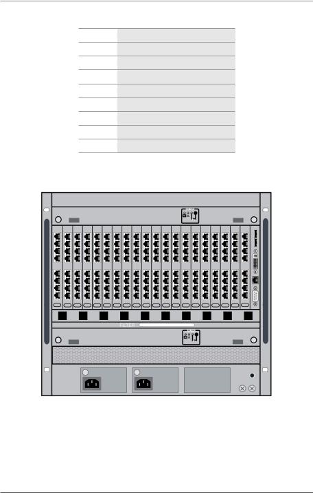
2.5.1 ServSwitch DKM FX 288-Port
|
|
|
|
|
|
|
|
|
|
|
|
|
|
|
|
|
|
|
|
|
|
|
|
|
|
|
|
|
|
|
|
|
|
|
|
|
|
|
|
|
|
|
|
|
|
|
|
|
|
|
|
|
|
|
|
|
|
|
|
|
|
|
|
|
|
|
|
|
|
|
|
|
|
|
|
|
|
|
|
1 |
2 |
3 |
4 |
5 |
6 |
7 |
8 |
||||||||
Figure 2-2. Front view, ACX288.
724-746-5500 | blackbox.com |
Page 21 |
Chapter 2: Overview
Table 2-4. ACX288 components.
Number Component
1Slot for Power Supply Unit 1
2Slot for Fan Tray 1
3Slot for Power Supply Unit 2
4Slot for Fan Tray 2
5Slot for I/O Boards 1–36
6Slot for Power Supply Unit 3
7Slot for CPU board
8Grounding
2.5.2ServSwitch DKM FX 160-Port
|
|
|
|
|
|
|
|
|
|
|
|
|
|
|
|
|
|
|
|
|
|
|
|
|
|
|
|
|
|
|
|
|
|
|
|
|
|
|
|
|
|
|
|
|
|
|
|
|
|
|
|
|
|
|
|
|
|
|
|
|
|
|
|
|
|
|
|
|
|
|
|
|
|
|
|
|
|
|
|
|
|
|
|
|
|
|
|
|
|
|
|
|
|
|
|
1 |
2 |
3 |
4 |
5 |
6 |
7 |
8 |
||||||||
Figure 2-3. Front view, ACX160.
Page 22 |
724-746-5500 | blackbox.com |
Chapter 2: Overview
Table 2-5. ACX160 components.
Number Component
1Slot for Power Supply Unit 1
2Slot for Fan Tray 1
3Slot for Power Supply Unit 2
4Slot for Fan Tray 2
5Slot for I/O Boards 1–20
6Slot for Power Supply Unit 3
7Slot for CPU board
8Grounding
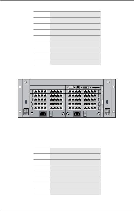
2.5.3ServSwitch DKM FX 80-Port
|
|
|
|
|
|
|
|
|
|
|
|
|
|
|
|
|
|
|
|
|
|
|
|
|
|
|
|
|
|
|
|
|
|
|
|
1 |
2 |
3 |
4 |
5 |
6 |
7 |
|||||
|
|
Figure 2-4. Front view, ACX080. |
|
|
|
||||||
Table 2-6. ACX080 components.
Number Component
1Slot for fan tray
2Slot for Power Supply Unit 1
3Slot for I/O Boards 1–10
4Slot for Power Supply Unit 2
5Slot for CPU board
6Slot for air filter
7Slot for Fan Tray 2
724-746-5500 | blackbox.com |
Page 23 |
Chapter 2: Overview
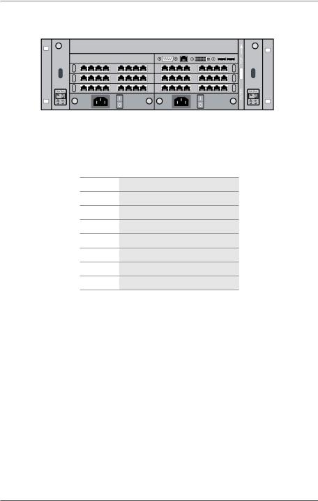
2.5.4 ServSwitch DKM FX 48-Port
|
|
|
|
|
|
|
|
|
|
|
|
|
|
|
|
|
|
|
|
|
|
|
|
|
|
|
|
|
|
|
|
|
|
|
|
|
|
|
|
|
|
1 |
|
2 |
3 |
4 |
5 |
6 |
7 |
||||||
Figure 2-5. Front view, ACX048.
Table 2-7. ACX048 components.
Number Component
1Slot for fan tray
2Slot for Power Supply Unit 1
3Slot for I/O Boards 1–10
4Slot for Power Supply Unit 2
5Slot for CPU board
6Slot for air filter
7Slot for Fan Tray 2
2.6Diagnostics and Status
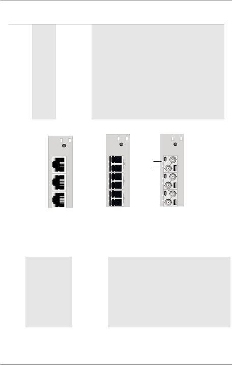
2.6.1 Status LEDs
The ServSwitch DKM FX components LED indicators are shown in Figures 2-6 through 2-11, and described in Tables 2-8 through 2-13.
Page 24 |
724-746-5500 | blackbox.com |

Chapter 2: Overview
1
2
Figure 2-6. CPU board, front view.
724-746-5500 | blackbox.com |
Page 25 |

Chapter 2: Overview
Table 2-8. Status LEDs on the CPU board.
Number |
LED |
Status |
Description |
|
|
|
|
|
|
White |
CPU board is in registration process |
|
|
|
|
|
|
Blue flashing |
Registration at the matrix is started |
|
|
|
|
1 |
Status 1 |
Red flashing |
Registration is in progess |
|
|
|
|
|
|
Green flashing |
Operating condition |
|
|
|
|
|
|
Green |
CPU board de-registered |
|
|
|
|
|
|
White |
CPU board is in registration process |
|
|
|
|
2 |
Status 2 |
Red flashing |
Registration at the matrix is started |
|
|
|
|
|
|
Off |
Operating condition |
|
|
|
|
NOTE: Because of variations in the LED type, “white” may also appear as light purple or light blue.
Page 26 |
724-746-5500 | blackbox.com |

Chapter 2: Overview
1 |
|
1 |
|
1 |
|
|
|
|
2 |
|
|
2 |
|
|
2 |
|
|
|
|
|||||
CATx |
SFP fiber |
SFP coax |
||||||
Figure 2-7. LEDs on the I/O boards.
724-746-5500 | blackbox.com |
Page 27 |
Chapter 2: Overview
Table 2-9. Status LEDs on the I/O boards.
Number |
LED |
Status |
Description |
|
|
|
|
|
|
|
|
Light blue |
I/O board in boot process |
|
|
|
|
|
|
1 |
Status 1 |
Red flashing |
I/O board in registration process |
|
|
|
|||
Green flashing |
Operating condition, I/O board registered at the matrix |
|||
|
|
|||
|
|
|
|
|
|
|
Green |
I/O board de-registered (locking pin pulled out) |
|
|
|
|
|
|
|
|
White |
I/O board in boot process |
|
|
|
|
|
|
|
|
Blue |
I/O board in registration process |
|
2 |
Status 2 |
|
|
|
Blue flashing |
Operating condition, communication active with CPU board |
|||
|
|
|||
|
|
active |
||
|
|
|
||
|
|
|
|
|
|
|
Red flashing |
I/O board de-registered (locking pin pulled out) |
|
|
|
|
|
1 |
|
|
1 |
|
|
|
1 |
|
|||||||
|
|
|
|
||||
2 |
|
2 |
|
|
2 |
||
|
|
|
|||||
|
|
|
|
|
|
|
|
|
CATx |
|
SFP fiber |
SFP coax |
|
Figure 2-8. Ports status LEDs on the I/O boards. |
|||
|
Table 2-10. Port status LEDs on the I/O boards. |
|||
|
|
|
|
|
Number |
LED |
Status |
Description |
|
|
|
|
|
|
|
|
Off |
Port not activated |
|
|
|
|
|
|
1 |
Link status (green) |
Flashing |
Port activated, no connection via interconnect cable |
|
|
|
|
|
|
|
|
On |
Connection via interconnect cable OK, data traffic active |
|
|
|
|
|
|
|
|
Off |
Port not activated |
|
|
|
|
|
|
2 |
Link status (orange) |
Flashing |
Port activated, no connection via interconnect cable |
|
|
|
|
|
|
|
|
On |
Connection via interconnect cable OK, data traffic active |
|
|
|
|
|
|
Page 28 |
724-746-5500 | blackbox.com |
Chapter 2: Overview
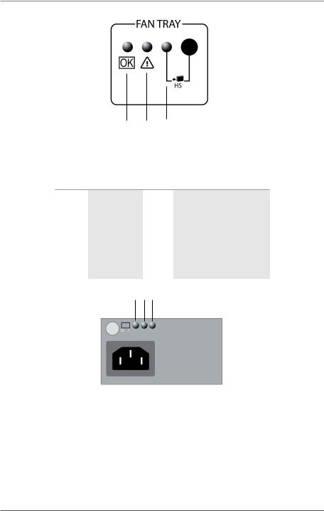
1 2 3
Figure 2-9. Status LEDs on the fan tray.
Table 2-11. Status LEDs on the fan tray.
Number |
LED |
|
Status |
Description |
|
|
|
|
|
|
|
1 |
Status 1 |
(green) On |
Operating condition |
||
|
|
|
|
|
|
2 |
Status 2 |
(blue) |
Off |
Operating condition |
|
|
|
||||
On |
Error indication |
||||
|
|
|
|||
|
|
|
|
|
|
3 |
Hot swap (blue) |
Off |
Hot swap option deactivated |
||
|
|
||||
On |
Hot swap option activated |
||||
|
|
|
|||
|
|
|
|
|
|
1 2 3
Figure 2-10. Status LEDs on the power supply unit (ACX288-PS or ACX160-PS).
724-746-5500 | blackbox.com |
Page 29 |
Chapter 2: Overview
Table 2-12. Status LEDs on the power supply unit (ACX288-PS or ACX160-PS).
Number |
LED |
Status |
Description |
|
|
|
|
|
|
1 |
AC input OK (green) |
On |
Operating condition |
|
|
|
|
|
|
2 |
DC output OK (green) |
On |
Operating condition |
|
|
|
|
|
|
3 |
O/T (yellow) |
Off |
Normal temperature |
|
|
|
|||
On |
High temperature |
|||
|
|
|||
|
|
|
|
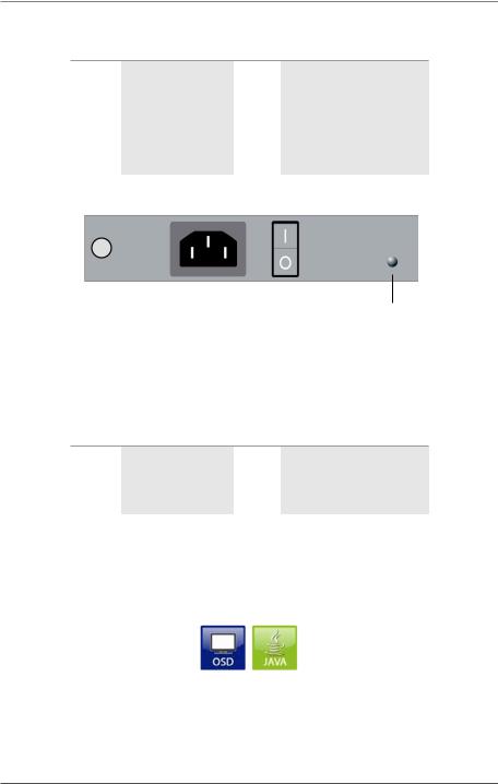
1
Figure 2-11. Status LEDs on the power supply unit (ACX080-PS).
Table 2-13. Status LEDs on the power supply unit (ACX080-PS).
Number LED |
Status |
Description |
||
|
|
|
|
|
1 |
DC input OK (green) |
On |
Operating condition |
|
|
|
|
||
DC output OK (green) |
Off |
No power supply |
||
|
||||
|
|
|
|
|
2.6.2 Port Status
The connections and the switching status between the various consoles and CPUs are shown in this menu.
You have the following possibilities to access the menu:
Figure 2-12. OSD and Java icons.
Page 30 |
724-746-5500 | blackbox.com |
 Loading...