

Page 1
Network Address Translation (NAT)
17.1 Overview
NAT (Network Address Translation - NAT, RFC 1631) is the translation of the IP address of a host in
a packet. For example, the source address of an outgoing packet, used within one network is
changed to a different IP address known within another network.
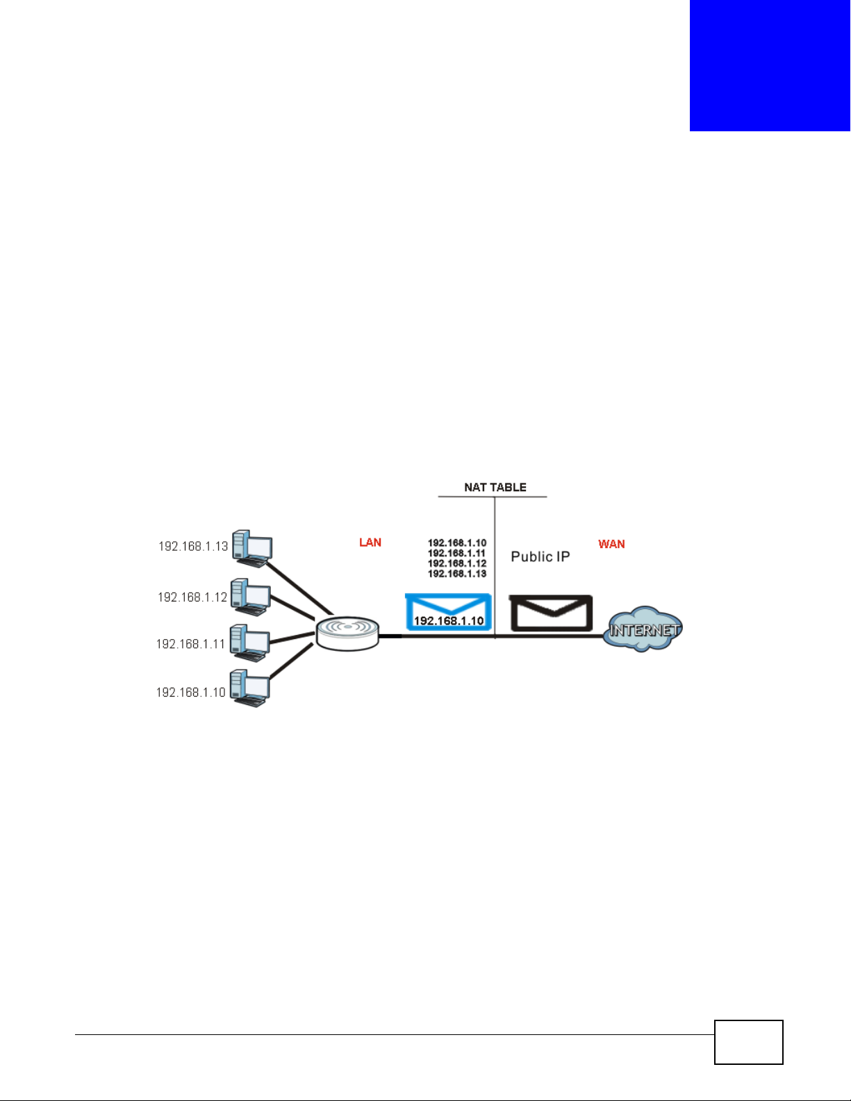
Each packet has two addresses – a source address and a destination address. For outgoing packets,
NAT maps private (local) IP addresses to globally unique ones required for communication with
hosts on other networks. It replaces the original IP source address in each packet and then
forwards it to the Internet. The Router keeps track of the original addresses and port numbers so
incoming reply packets can have their original values restored. The following figure illustrates this.
Figure 99 NAT Example
CHAPTER 17
For more information on IP address translation, refer to RFC 1631, The IP Network Address
Translator (NAT).
17.2 What You Can Do
•Use the General screen (Section 17.3 on page 142) to enable NAT and set a default server.
•Use the Application screen (Section 17.4 on page 142) o forward incoming service requests to
the server(s) on your local network.
•Use the Advanced screen (Section 17.5 on page 144) to change your Router’s trigger port
settings.
NBG-419N v2 User’s Guide 141
Page 2
Chapter 17 Network Address Translation (NAT)
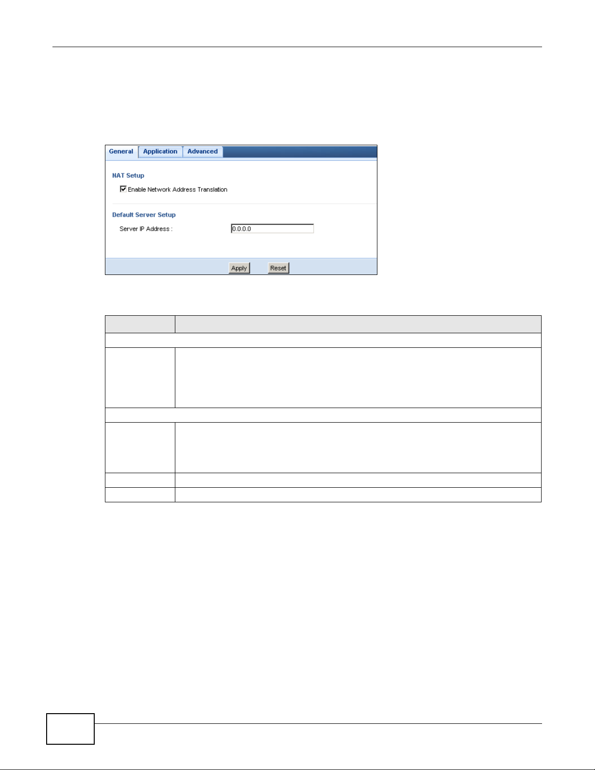
17.3 General NAT Screen
Use this screen to enable NAT and set a default server. Click Network > NAT > General to open
the following screen.
Figure 100 Network > NAT > General
The following table describes the labels in this screen.
Table 62 Network > NAT > General
LABEL DESCRIPTION
NAT Setup
Enable Network
Address
Tra n s l a tion
Network Address Translation (NAT) allows the translation of an Internet protocol address
used within one network (for example a private IP address used in a local network) to a
different IP address known within another network (for example a public IP address used on
the Internet).
Select the check box to enable NAT.
Default Server Setup
Server IP
Address
Apply Click Apply to save your changes back to the Router.
Reset Click Reset to begin configuring this screen afresh.
In addition to the servers for specified services, NAT supports a default server. A default
server receives packets from ports that are not specified in the Application screen.
If you do not assign a Default Server IP address, the Router discards all packets received
for ports that are not specified in the Application screen or remote management.
17.4 NAT Application Screen
Use the Application screen to forward incoming service requests to the server(s) on your local
network. You may enter a single port number or a range of port numbers to be forwarded, and the
local IP address of the desired server. The port number identifies a service; for example, web
service is on port 80 and FTP on port 21. In some cases, such as for unknown services or where one
server can support more than one service (for example both FTP and web service), it might be
better to specify a range of port numbers.
In addition to the servers for specified services, NAT supports a default server. A service request
that does not have a server explicitly designated for it is forwarded to the default server. If the
default is not defined, the service request is simply discarded.
142
NBG-419N v2 User’s Guide
Page 3
Chapter 17 Network Address Translation (NAT)
Note: Many residential broadband ISP accounts do not allow you to run any server
processes (such as a Web or FTP server) from your location. Your ISP may
periodically check for servers and may suspend your account if it discovers any
active services at your location. If you are unsure, refer to your ISP.
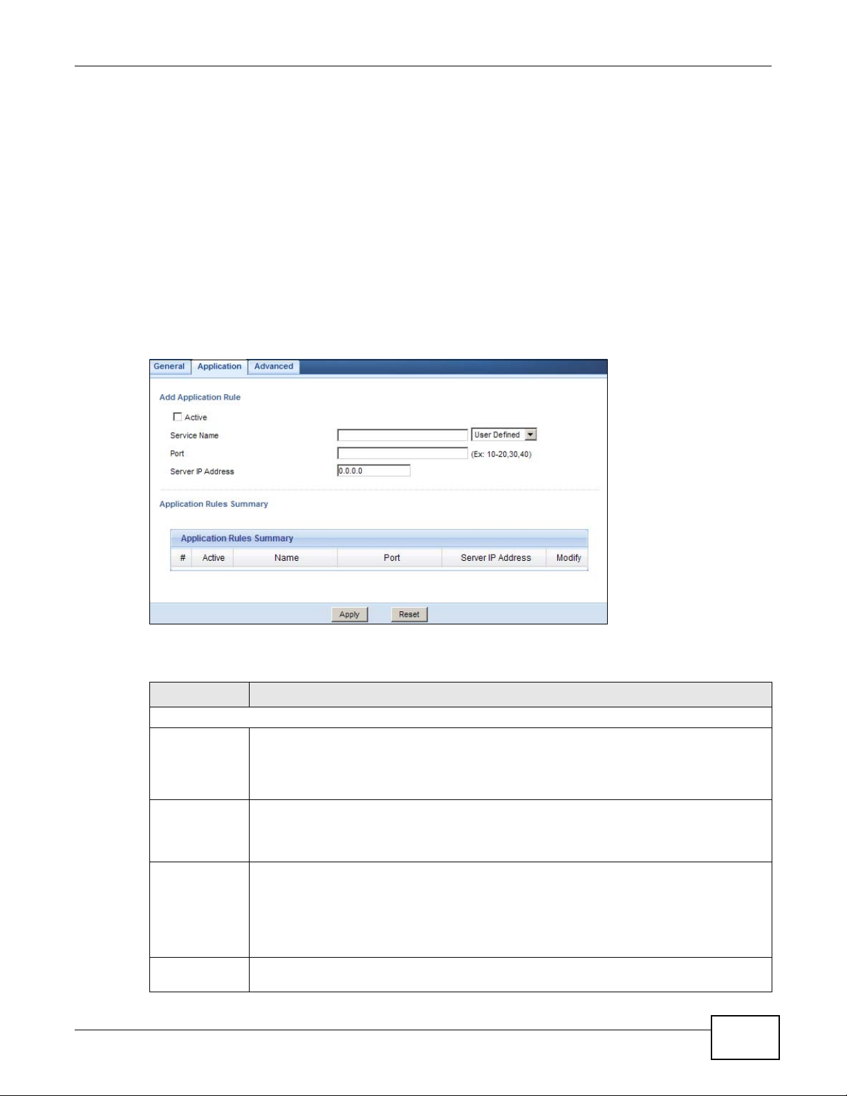
Port forwarding allows you to define the local servers to which the incoming services will be
forwarded. To change your Router’s port forwarding settings, click Network > NAT > Application.
The screen appears as shown.
Note: If you do not assign a Default Server IP address in the NAT > General screen,
the Router discards all packets received for ports that are not specified in this
screen or remote management.
Refer to Appendix E on page 263 for port numbers commonly used for particular services.
Figure 101 Network > NAT > Application
The following table describes the labels in this screen.
Table 63 Network > NAT > Application
LABEL DESCRIPTION
Add Application Rule
Active Select the check box to enable this rule and the requested service can be forwarded to the
Service Name Type a name (of up to 31 printable characters) to identify this rule in the first field next to
Port Type a port number(s) to define the service to be forwarded to the specified server.
Server IP
Address
NBG-419N v2 User’s Guide
host with a specified internal IP address.
Clear the checkbox to disallow forwarding of these ports to an inside server without having
to delete the entry.
Service Name. Otherwise, select a predefined service in the second field next to Service
Name. The predefined service name and port number(s) will display in the Service Name
and Port fields.
To specify a range of ports, enter a hyphen (-) between the first port and the last port, such
as 10-20.
To specify two or more non-consecutive port numbers, separate them by a comma without
spaces, such as 123,567.
Type the IP address of the server on your LAN that receives packets from the port(s)
specified in the Port field.
143
Page 4
Chapter 17 Network Address Translation (NAT)
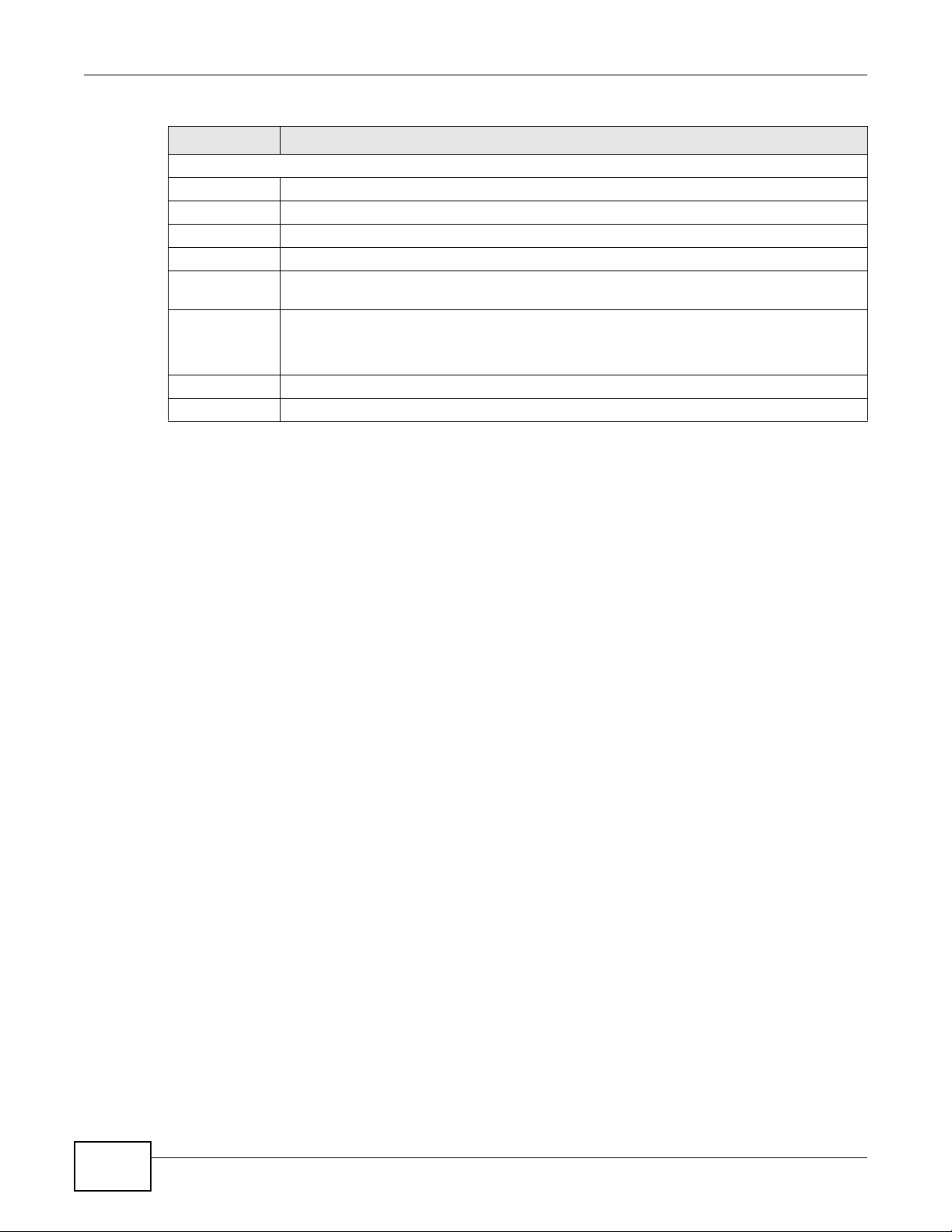
Table 63 Network > NAT > Application (continued)
LABEL DESCRIPTION
Application Rules Summary
# This is the number of an individual port forwarding server entry.
Active This icon is turned on when the rule is enabled.
Name This field displays a name to identify this rule.
Port This field displays the port number(s).
Server IP
Address
Modify Click the Edit icon to display and modify an existing rule setting in the fields under Add
Apply Click Apply to save your changes back to the Router.
Reset Click Reset to begin configuring this screen afresh.
This field displays the inside IP address of the server.
Application Rule.
Click the Remove icon to delete a rule.
17.5 NAT Advanced Screen
Some services use a dedicated range of ports on the client side and a dedicated range of ports on
the server side. With regular port forwarding you set a forwarding port in NAT to forward a service
(coming in from the server on the WAN) to the IP address of a computer on the client side (LAN).
The problem is that port forwarding only forwards a service to a single LAN IP address. In order to
use the same service on a different LAN computer, you have to manually replace the LAN
computer's IP address in the forwarding port with another LAN computer's IP address.
Trigger port forwarding solves this problem by allowing computers on the LAN to dynamically take
turns using the service. The Router records the IP address of a LAN computer that sends traffic to
the WAN to request a service with a specific port number and protocol (a "trigger" port). When the
Router's WAN port receives a response with a specific port number and protocol ("incoming" port),
the Router forwards the traffic to the LAN IP address of the computer that sent the request. After
that computer’s connection for that service closes, another computer on the LAN can use the
service in the same manner. This way you do not need to configure a new IP address each time you
want a different LAN computer to use the application.
To change your Router’s trigger port settings, click Network > NAT > Advanced. The screen
appears as shown.
144
NBG-419N v2 User’s Guide
Page 5
Chapter 17 Network Address Translation (NAT)
Note: Only one LAN computer can use a trigger port (range) at a time.
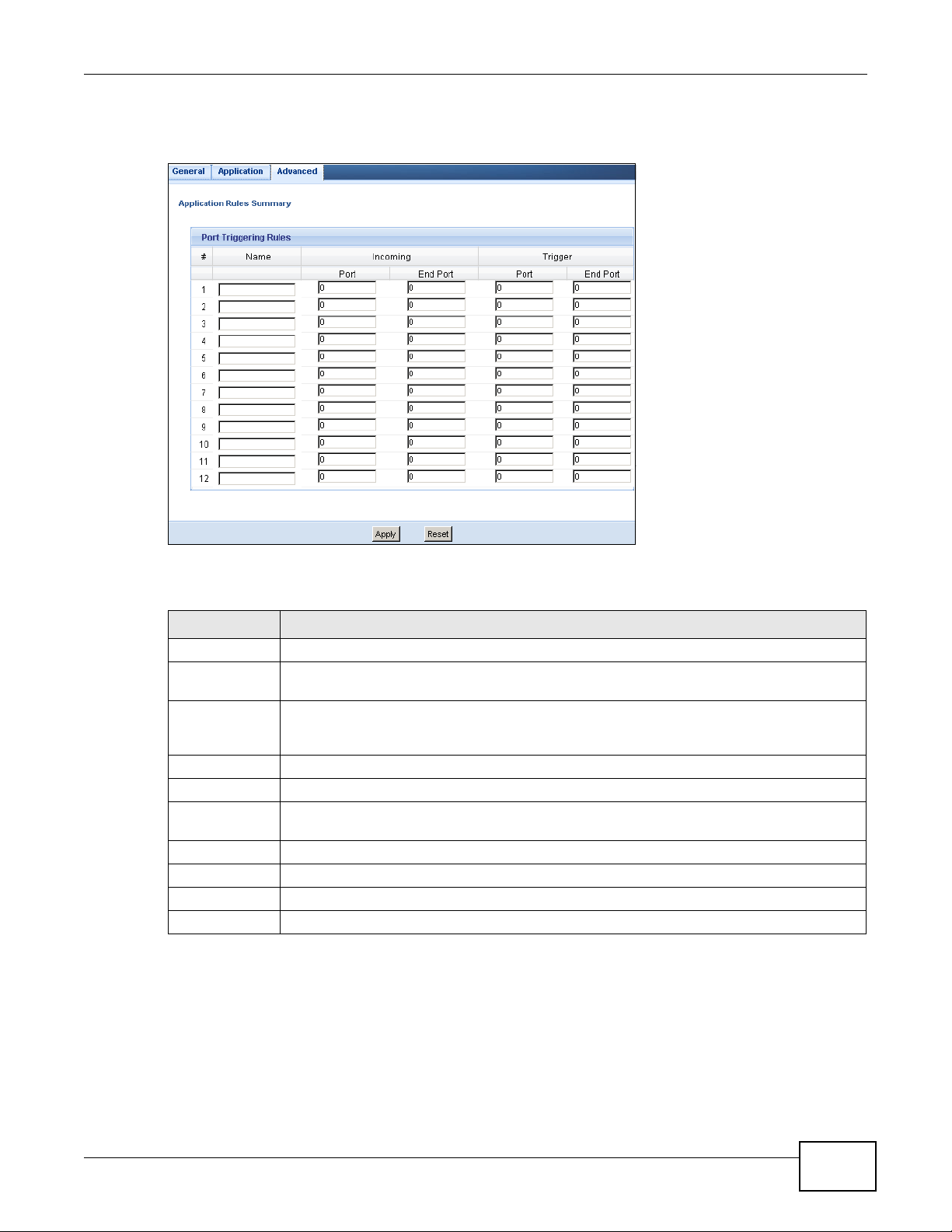
Figure 102 Network > NAT > Advanced
The following table describes the labels in this screen.
Table 64 Network > NAT > Advanced
LABEL DESCRIPTION
# This is the rule index number (read-only).
Name Type a unique name (up to 15 characters) for identification purposes. All characters are
permitted - including spaces.
Incoming Incoming is a port (or a range of ports) that a server on the WAN uses when it sends out a
Start Port Type a port number or the starting port number in a range of port numbers.
End Port Type a port number or the ending port number in a range of port numbers.
Trigger The trigger port is a port (or a range of ports) that causes (or triggers) the Router to record
Start Port Type a port number or the starting port number in a range of port numbers.
End Port Type a port number or the ending port number in a range of port numbers.
Apply Click Apply to save your changes back to the Router.
Reset Click Reset to begin configuring this screen afresh.
particular service. The Router forwards the traffic with this port (or range of ports) to the
client computer on the LAN that requested the service.
the IP address of the LAN computer that sent the traffic to a server on the WAN.
NBG-419N v2 User’s Guide
145
Page 6
Chapter 17 Network Address Translation (NAT)
Router
Router
17.5.1 Trigger Port Forwarding Example
The following is an example of trigger port forwarding.
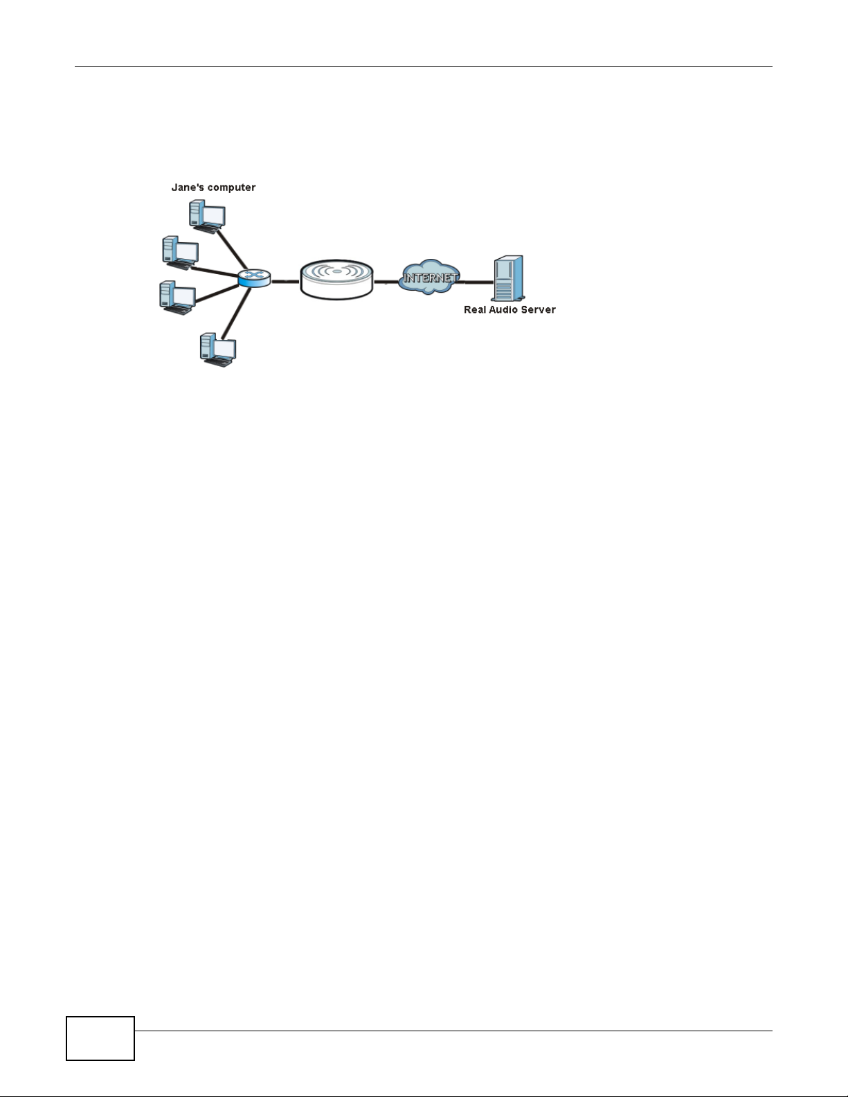
Figure 103 Trigger Port Forwarding Process: Example
1 Jane requests a file from the Real Audio server (port 7070).
2 Port 7070 is a “trigger” port and causes the Router to record Jane’s computer IP address. The
Router associates Jane's computer IP address with the "incoming" port range of 6970-7170.
3 The Real Audio server responds using a port number ranging between 6970-7170.
4 The Router forwards the traffic to Jane’s computer IP address.
5 Only Jane can connect to the Real Audio server until the connection is closed or times out. The
Router times out in three minutes with UDP (User Datagram Protocol), or two hours with TCP/IP
(Transfer Control Protocol/Internet Protocol).
17.5.2 Two Points To Remember About Trigger Ports
1 Trigger events only happen on data that is going coming from inside the Router and going to the
outside.
If an application needs a continuous data stream, that port (range) will be tied up so that another
computer on the LAN can’t trigger it.
146
NBG-419N v2 User’s Guide
Page 7
CHAPTER 18
18.1 Overview
Dynamic DNS (DDNS) services let you use a domain name with a dynamic IP address.
18.2 What You Can Do
Use the Dynamic DNS screen (Section 18.4 on page 147) to enable DDNS and configure the DDNS
settings on the Router.
18.3 What You Need To Know
Dynamic DNS
Dynamic DNS allows you to update your current dynamic IP address with one or many dynamic
DNS services so that anyone can contact you (in NetMeeting, CU-SeeMe, etc.). You can also access
your FTP server or Web site on your own computer using a domain name (for instance
myhost.dhs.org, where myhost is a name of your choice) that will never change instead of using an
IP address that changes each time you reconnect. Your friends or relatives will always be able to
call you even if they don't know your IP address.
18.4 Dynamic DNS Screen
To change your Router’s DDNS, click Network > DDNS. The screen appears as shown.
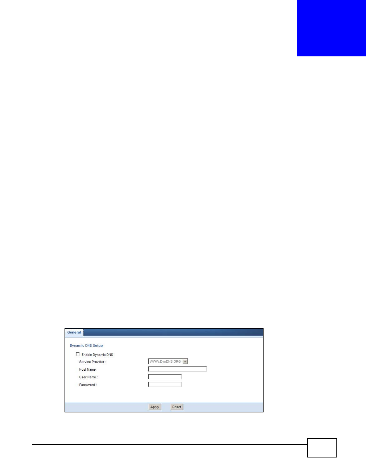
Figure 104 Network > DDNS
NBG-419N v2 User’s Guide 147
Page 8
Chapter 18 Dynamic DNS
The following table describes the labels in this screen.
Table 65 Network > DDNS
LABEL DESCRIPTION
Enable
Dynamic DNS
Service
Provider
Host Name Enter a host names in the field provided. You can specify up to two host names in the field
User Name Enter your user name.
Password Enter the password assigned to you.
Apply Click Apply to save your changes back to the Router.
Reset Click Reset to begin configuring this screen afresh.
Select this check box to use dynamic DNS.
Select the name of your Dynamic DNS service provider.
separated by a comma (",").
148
NBG-419N v2 User’s Guide
Page 9
19.1 Overview
This chapter shows you how to configure static routes for your Router.
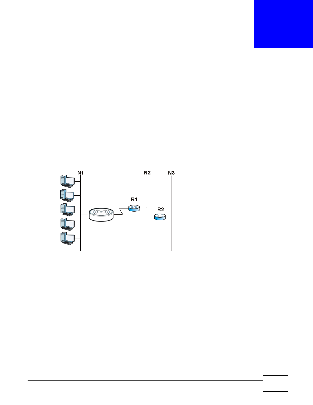
Each remote node specifies only the network to which the gateway is directly connected, and the
Router has no knowledge of the networks beyond. For instance, the Router knows about network
N2 in the following figure through remote node Router 1. However, the Router is unable to route a
packet to network N3 because it doesn't know that there is a route through the same remote node
Router 1 (via gateway Router 2). The static routes are for you to tell the Router about the networks
beyond the remote nodes.
Figure 105 Example of Static Routing Topology
CHAPTER 19
Static Route
19.2 What You Can Do
Use the IP Static Route screen (Section 19.3 on page 150) to view, add and delete routes.
NBG-419N v2 User’s Guide 149
Page 10
Chapter 19 Static Route
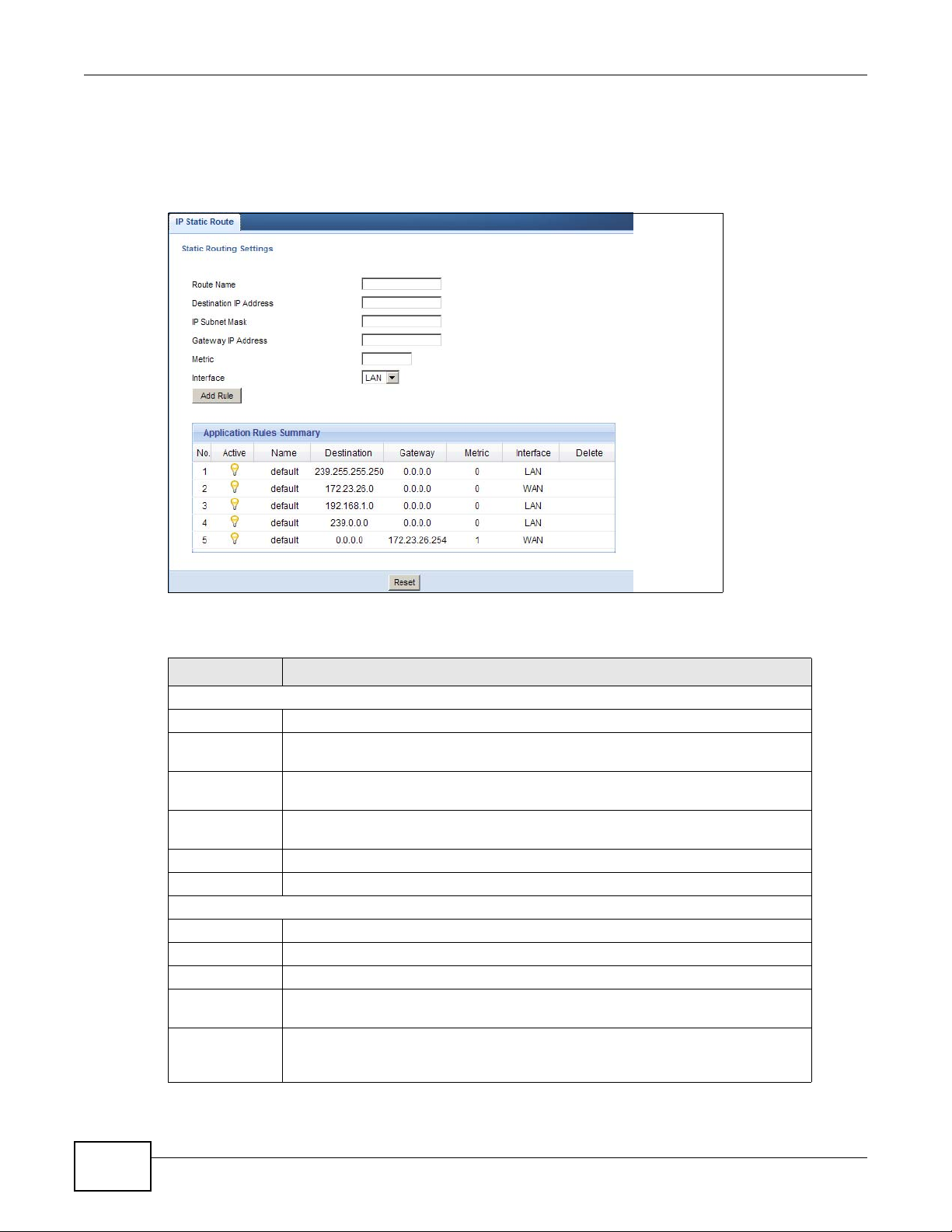
19.3 IP Static Route Screen
Click Network > Static Route to open the IP Static Route screen.
Figure 106 Network > Static Route
The following table describes the labels in this screen.
Table 66 Network > Static Route
LABEL DESCRIPTION
Static Routing Settings
Route Name Enter a the name that describes or identifies this route.
Destination IP
Address
IP Subnet
Netmask
Gateway IP
Address
Metric Assign a number to identify the route.
Add Rule Click this to add the IP static route.
Application Rules Summary
No. This is the number of an individual static route.
Active The rules are always on and this is indicated by the icon.
Name This is the name that describes or identifies this route.
Destination This parameter specifies the IP network address of the final destination. Routing is
Gateway This is the IP address of the gateway. The gateway is a router or switch on the
Enter the IP network address of the final destination.
This is the subnet to which the route’s final destination belongs.
Enter the the IP address of the gateway.
always based on network number.
same network segment as the device's LAN or WAN port. The gateway helps
forward packets to their destinations.
150
NBG-419N v2 User’s Guide
Page 11

Chapter 19 Static Route
Table 66 Network > Static Route
LABEL DESCRIPTION
Metric This is the number assigned to the route.
Delete Click the Delete icon to remove a static route from the Router. A window displays
asking you to confirm that you want to delete the route.
NBG-419N v2 User’s Guide
151
Page 12

Chapter 19 Static Route
152
NBG-419N v2 User’s Guide
Page 13
20.1 Overview
Routing Information Protocol (RIP) is an interior or intra-domain routing protocol that uses
distance-vector routing algorithms. RIP is used on the Internet and is common in the NetWare
environment as a method for exchanging routing information between routers.
20.2 What You Can Do
Use the RIP screen (Section 20.3 on page 153) to enable RIPv1 or RIPv2, which are LAN broadcast
protocols.
CHAPTER 20
RIP
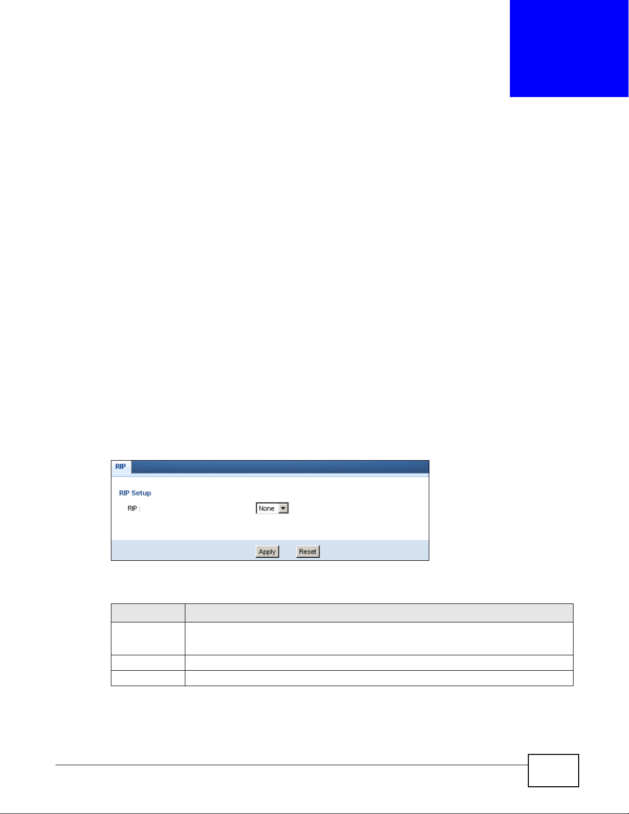
20.3 RIP Screen
Use this screen to enable RIPv1 or RIPv2, which are LAN broadcast protocols. Click Network >
RIP. The screen appears as shown.
Figure 107 Network > RIP
The following table describes the labels in this screen.
Table 67 Network > RIP
LABEL DESCRIPTION
RIP Select the RIPv1 or RIPv2 you want the Router to use.
Otherwise select None.
Apply Click Apply to save your changes back to the Router.
Reset Click Reset to begin configuring this screen afresh.
NBG-419N v2 User’s Guide 153
Page 14

Chapter 20 RIP
154
NBG-419N v2 User’s Guide
Page 15
21.1 Overview
This chapter shows you how to enable and configure the firewall that protects your Router and your
LAN from unwanted or malicious traffic.
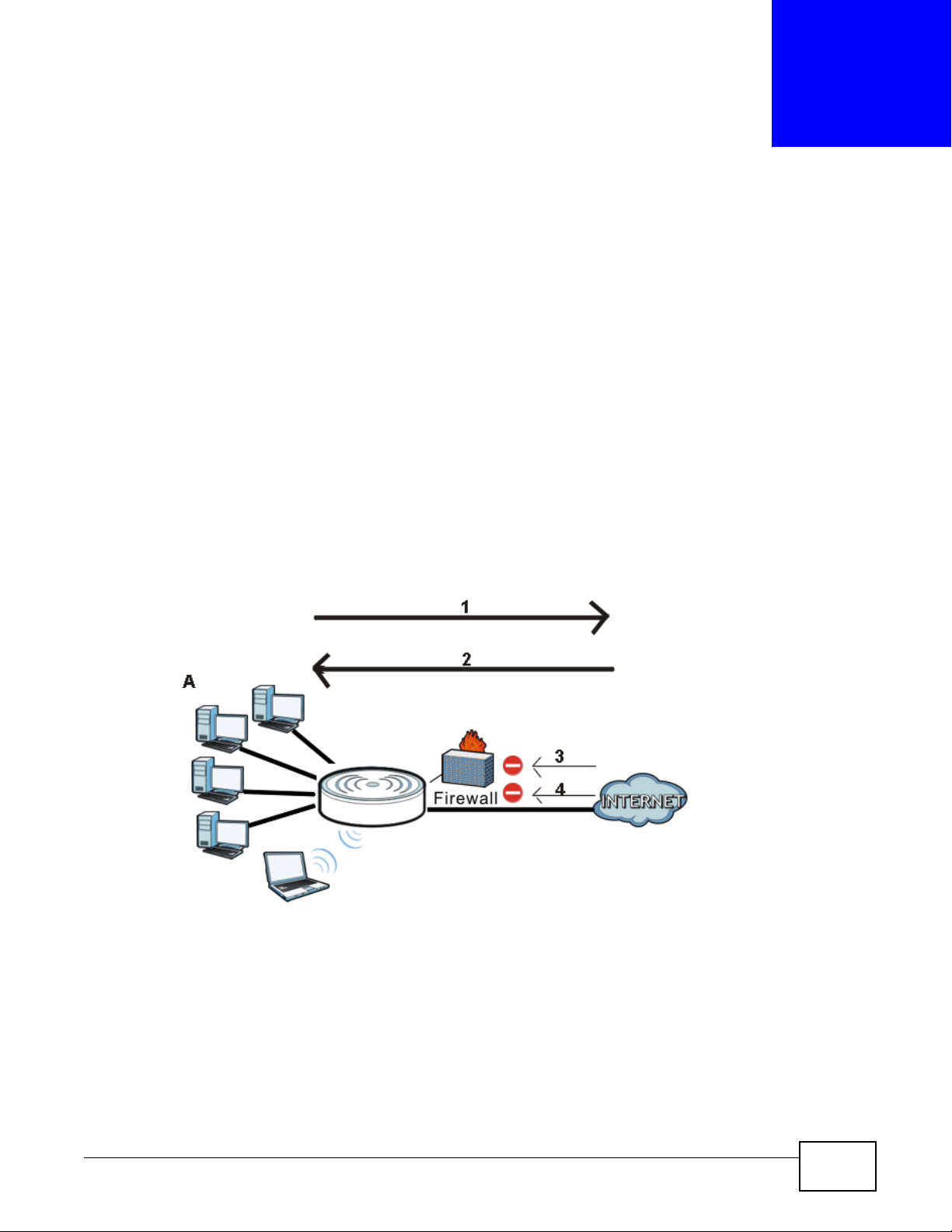
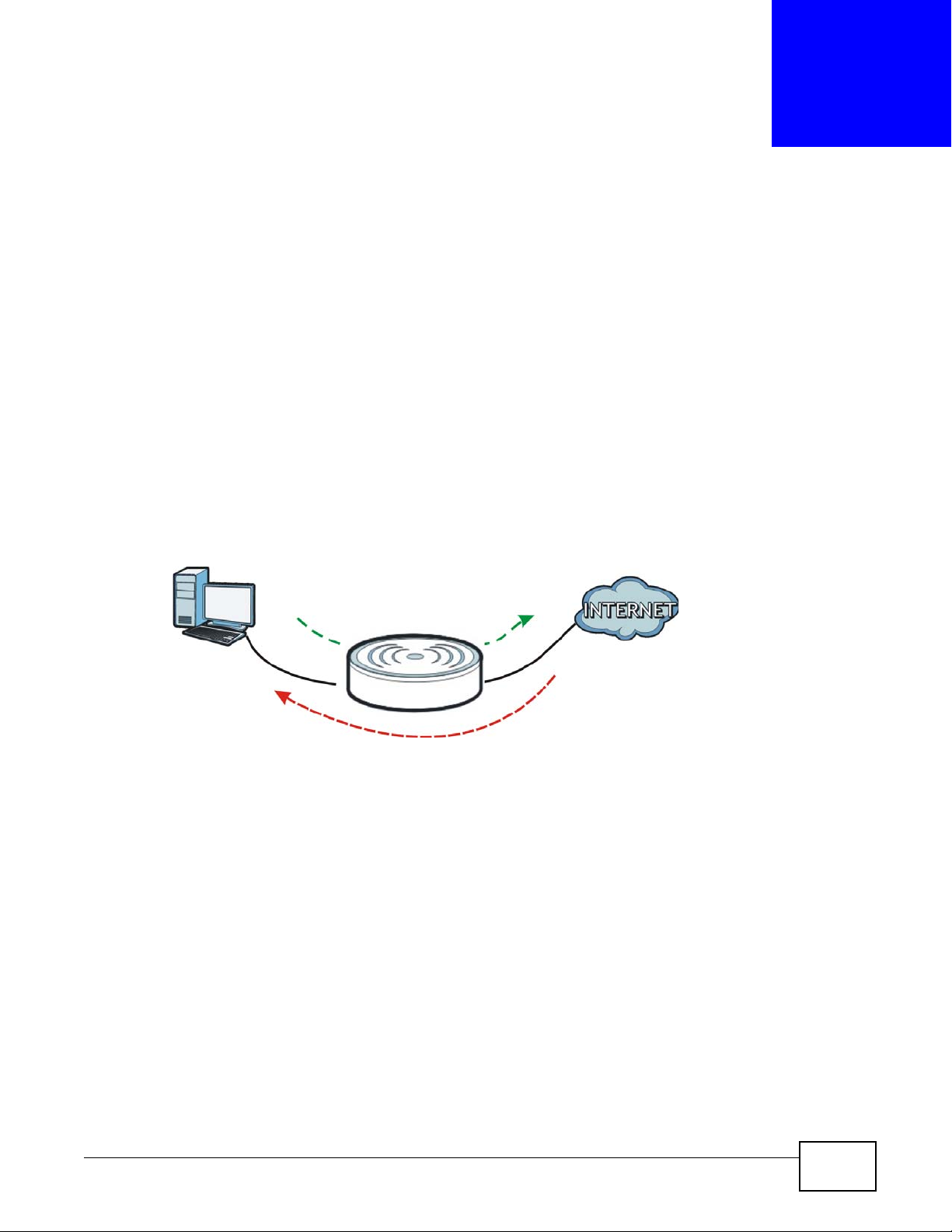
Enable the firewall to protect your LAN computers from attacks by hackers on the Internet and
control access between the LAN and WAN. By default the firewall:
• allows traffic that originates from your LAN computers to go to all of the networks.
• blocks traffic that originates on the other networks from going to the LAN.
The following figure illustrates the default firewall action. User A can initiate an IM (Instant
Messaging) session from the LAN to the WAN (1). Return traffic for this session is also allowed (2).
However other traffic initiated from the WAN is blocked (3 and 4).
CHAPTER 21
Firewall
Figure 108 Default Firewall Action
21.2 What You Can Do
•Use the General (Section 21.4 on page 156) screen to enable or disable the Router’s firewall.
•Use the Services screen (Section 21.5 on page 157) screen enable service blocking, enter/
delete/modify the services you want to block and the date/time you want to block them.
NBG-419N v2 User’s Guide 155
Page 16
Chapter 21 Firewall
21.3 What You Need To Know
The Router’s firewall feature physically separates the LAN and the WAN and acts as a secure
gateway for all data passing between the networks.
It is designed to protect against Denial of Service (DoS) attacks when activated (click the General
tab under Firewall and then click the Enable Firewall check box). The Router's purpose is to
allow a private Local Area Network (LAN) to be securely connected to the Internet. The Router can
be used to prevent theft, destruction and modification of data, as well as log events, which may be
important to the security of your network.
The Router is installed between the LAN and a broadband modem connecting to the Internet. This
allows it to act as a secure gateway for all data passing between the Internet and the LAN.
The Router has one Ethernet WAN port and four Ethernet LAN ports, which are used to physically
separate the network into two areas.The WAN (Wide Area Network) port attaches to the broadband
(cable or DSL) modem to the Internet.
The LAN (Local Area Network) port attaches to a network of computers, which needs security from
the outside world. These computers will have access to Internet services such as e-mail, FTP and
the World Wide Web. However, "inbound access" is not allowed (by default) unless the remote host
is authorized to use a specific service.
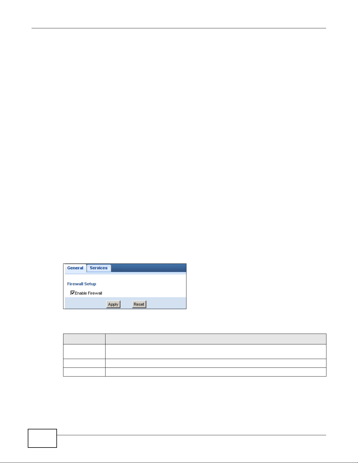
21.4 General Firewall Screen
Use this screen to enable or disable the Router’s firewall, and set up firewall logs. Click Security >
Firewall to open the General screen.
Figure 109 Security > Firewall > General
The following table describes the labels in this screen.
Table 68 Security > Firewall > General
LABEL DESCRIPTION
Enable Firewall Select this check box to activate the firewall. The Router performs access control and
protects against Denial of Service (DoS) attacks when the firewall is activated.
Apply Click Apply to save the settings.
Reset Click Reset to start configuring this screen again.
156
NBG-419N v2 User’s Guide
Page 17
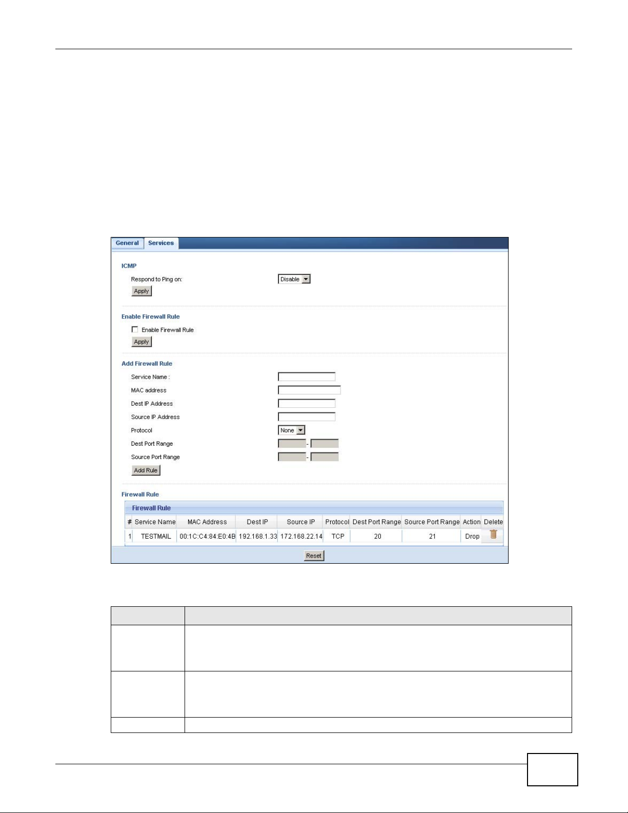
21.5 Services Screen
If an outside user attempts to probe an unsupported port on your Router, an ICMP response packet
is automatically returned. This allows the outside user to know the Router exists. Use this screen to
prevent the ICMP response packet from being sent. This keeps outsiders from discovering your
Router when unsupported ports are probed.
You can also use this screen to enable service blocking, enter/delete/modify the services you want
to block and the date/time you want to block them.
Click Security > Firewall > Services. The screen appears as shown next.
Figure 110 Security > Firewall > Services
Chapter 21 Firewall
The following table describes the labels in this screen.
Table 69 Security > Firewall > Services
LABEL DESCRIPTION
ICMP Internet Control Message Protocol is a message control and error-reporting protocol
Respond to
Ping on
Apply Click Apply to save the settings.
NBG-419N v2 User’s Guide
between a host server and a gateway to the Internet. ICMP uses Internet Protocol (IP)
datagrams, but the messages are processed by the TCP/IP software and directly apparent
to the application user.
The Router will not respond to any incoming Ping requests when Disable is selected. Select
LAN to reply to incoming LAN Ping requests. Select WAN to reply to incoming WAN Ping
requests. Otherwise select LAN & WAN to reply to all incoming LAN and WAN Ping
requests.
157
Page 18

Chapter 21 Firewall
Table 69 Security > Firewall > Services (continued)
LABEL DESCRIPTION
Enable Firewall Rule
Enable Firewall
Rule
Apply Click Apply to save the settings.
Add Firewall Rule
Service Name Enter a name that identifies or describes the firewall rule.
MAC Address Enter the MAC address of the computer for which the firewall rule applies.
Dest IP Address Enter the IP address of the computer to which traffic for the application or service is
Source IP
Address
Protocol Select the protocol (TCP, UDP, ICMP or None) used to transport the packets for which you
Dest Port
Range
Source Port
Range
Add Rule Click Add to save the firewall rule.
Firewall Rule
# This is your firewall rule number. The ordering of your rules is important as rules are applied
Service Name This is a name that identifies or describes the firewall rule.
MAC Address This is the MAC address of the computer for which the firewall rule applies.
Dest IP Address This is the IP address of the computer to which traffic for the application or service is
Source IP
Address
Protocol This is the protocol (TCP, UDP, ICMP or None) used to transport the packets for which you
Dest Port
Range
Source Port
Range
Action Drop - Traffic matching the conditions of the firewall rule are stopped.
Delete Click this to remove the firewall rule.
Reset Click Reset to start configuring this screen again.
Select this check box to activate the firewall rules that you define (see Add Firewall Rule
below)
entering.
The Router applies the firewall rule to traffic initiating from this computer.
Enter the IP address of the computer that initializes traffic for the application or service.
The Router applies the firewall rule to traffic initiating from this computer.
want to apply the firewall rule.
Enter the port number/range of the destination that define the traffic type, for example TCP
port 80 defines web traffic.
Enter the port number/range of the source that define the traffic type, for example TCP port
80 defines web traffic.
in turn.
entering.
This is the IP address of the computer from which traffic for the application or service is
initialized.
want to apply the firewall rule.
This is the port number/range of the destination that define the traffic type, for example
TCP port 80 defines web traffic.
This is the port number/range of the source that define the traffic type, for example TCP
port 80 defines web traffic.
158
See Appendix E on page 263 for commonly used services and port numbers.
NBG-419N v2 User’s Guide
Page 19

22.1 Overview
This chapter provides a brief overview of content filtering using the embedded web GUI.
Internet content filtering allows you to create and enforce Internet access policies tailored to your
needs. Content filtering is the ability to block certain web features or specific URL keywords.
22.2 What You Can Do
Use the Content Filter (Section 22.4 on page 160) screen to restrict web features, add
keywords for blocking and designate a trusted computer.
CHAPTER 22
Content Filter
22.3 What You Need To Know
Content filtering allows you to block certain web features, such as cookies, and/or block access to
specific web sites. For example, you can configure one policy that blocks John Doe’s access to arts
and entertainment web pages.
22.3.1 Content Filtering Profiles
A content filtering profile conveniently stores your custom settings for the following features.
Restrict Web Features
The Router can disable web proxies and block web features such as ActiveX controls, Java applets
and cookies.
Keyword Blocking URL Checking
The Router checks the URL’s domain name (or IP address) and file path separately when performing
keyword blocking.
The URL’s domain name or IP address is the characters that come before the first slash in the URL.
For example, with the URL www.zyxel.com.tw/news/pressroom.php
www.zyxel.com.tw
.
, the domain name is
The file path is the characters that come after the first slash in the URL. For example, with the URL
www.zyxel.com.tw/news/pressroom.php
NBG-419N v2 User’s Guide 159
, the file path is news/pressroom.php.
Page 20
Chapter 22 Content Filter
Since the Router checks the URL’s domain name (or IP address) and file path separately, it will not
find items that go across the two. For example, with the URL www.zyxel.com.tw/news/
pressroom.php, the Router would find “tw” in the domain name (www.zyxel.com.tw). It would also
find “news” in the file path (news/pressroom.php
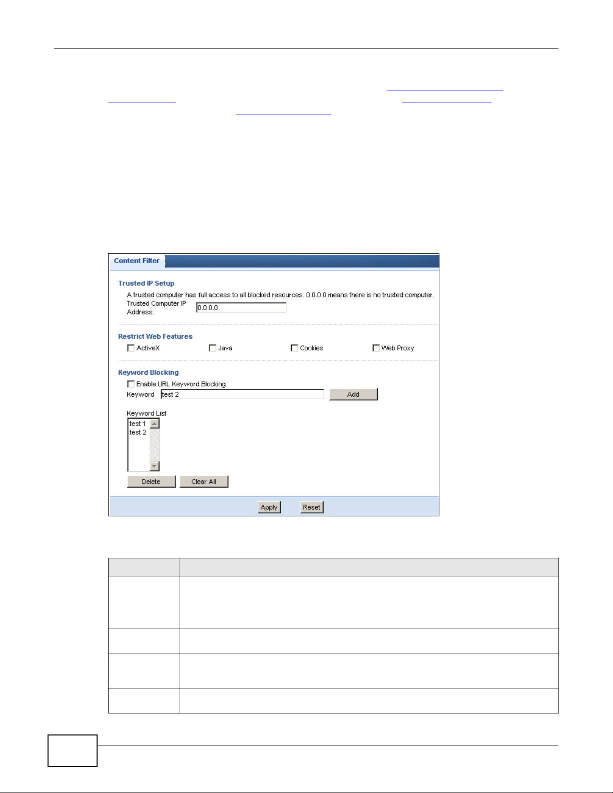
22.4 Content Filter Screen
Use this screen to restrict web features, add keywords for blocking and designate a trusted
computer.
Click Security > Content Filter to open the Content Filter screen.
Figure 111 Security > Content Filter > Content Filter
) but it would not find “tw/news”.
160
The following table describes the labels in this screen.
Table 70 Security > Content Filter > Content Filter
LABEL DESCRIPTION
Trusted IP
Setup
Restrict Web
Features
ActiveX A tool for building dynamic and active Web pages and distributed object applications. When
Java A programming language and development environment for building downloadable Web
To enable this feature, type an IP address of any one of the computers in your network that
you want to have as a trusted computer. This allows the trusted computer to have full
access to all features that are configured to be blocked by content filtering.
Leave this field blank to have no trusted computers.
Select the box(es) to restrict a feature. When you download a page containing a restricted
feature, that part of the web page will appear blank or grayed out.
you visit an ActiveX Web site, ActiveX controls are downloaded to your browser, where they
remain in case you visit the site again.
components or Internet and intranet business applications of all kinds.
NBG-419N v2 User’s Guide
Page 21

Chapter 22 Content Filter
Table 70 Security > Content Filter > Content Filter (continued)
LABEL DESCRIPTION
Cookies Used by Web servers to track usage and provide service based on ID.
Web Proxy A server that acts as an intermediary between a user and the Internet to provide security,
administrative control, and caching service. When a proxy server is located on the WAN it is
possible for LAN users to circumvent content filtering by pointing to this proxy server.
Enable URL
Keyword
Blocking
Keyword Type a keyword in this field. You may use any character (up to 64 characters). Wildcards are
Keyword List This list displays the keywords already added.
Add Click Add after you have typed a keyword.
Delete Highlight a keyword in the lower box and click Delete to remove it. The keyword disappears
Clear All Click this button to remove all of the listed keywords.
Apply Click Apply to save your changes.
Reset Click Reset to begin configuring this screen afresh
The Router can block Web sites with URLs that contain certain keywords in the domain name
or IP address. For example, if the keyword "bad" was enabled, all sites containing this
keyword in the domain name or IP address will be blocked, e.g., URL http://
www.website.com/bad.html would be blocked. Select this check box to enable this feature.
not allowed. You can also enter a numerical IP address.
Repeat this procedure to add other keywords. Up to 64 keywords are allowed.
When you try to access a web page containing a keyword, you will get a message telling you
that the content filter is blocking this request.
from the text box after you click Apply.
NBG-419N v2 User’s Guide
161
Page 22

Chapter 22 Content Filter
162
NBG-419N v2 User’s Guide
Page 23
23.1 Overview
A
B
-> VOIP
-> FTP
-> HTTP
-> Chat, Email
This chapter contains information about configuring bandwidth management and editing rules.
ZyXEL’s Bandwidth Management allows you to specify bandwidth management rules based on an
application.
In the figure below, uplink traffic goes from the LAN device (A) to the WAN device (B). Bandwidth
management is applied before sending the packets out to the WAN. Downlink traffic comes back
from the WAN device (B) to the LAN device (A). Bandwidth management is applied before sending
the traffic out to LAN.
Figure 112 Bandwidth Management Example
CHAPTER 23
Bandwidth Management
You can allocate specific amounts of bandwidth capacity (bandwidth budgets) to individual
applications (like VoIP, Web, FTP, and E-mail for example).
23.2 What You Can Do
•Use the General screen (Section 23.4 on page 164) to enable bandwidth management and
assign bandwidth values.
•Use the Advanced screen (Section 23.5 on page 164) to configure bandwidth managements rule
for the pre-defined services and applications.
•Use the Monitor screen (Section 23.6 on page 168) to view the amount of network bandwidth
that applications running in the network are using.
NBG-419N v2 User’s Guide 163
Page 24
Chapter 23 Bandwidth Management
23.3 What You Need To Know
The sum of the bandwidth allotments that apply to the WAN interface (LAN to WAN, WLAN to WAN)
must be less than or equal to the Upstream Bandwidth that you configure in the Bandwidth
Management Advanced screen (Section 23.5 on page 164).
The sum of the bandwidth allotments that apply to the LAN interface (WAN to LAN, WAN to WLAN)
must be less than or equal to the Downstream Bandwidth that you configure in the Bandwidth
Management Advanced screen Section 23.5 on page 164.
23.4 General Screen
Use this screen to have the Router apply bandwidth management.
Click Management > Bandwidth Management to open the bandwidth management General
screen.
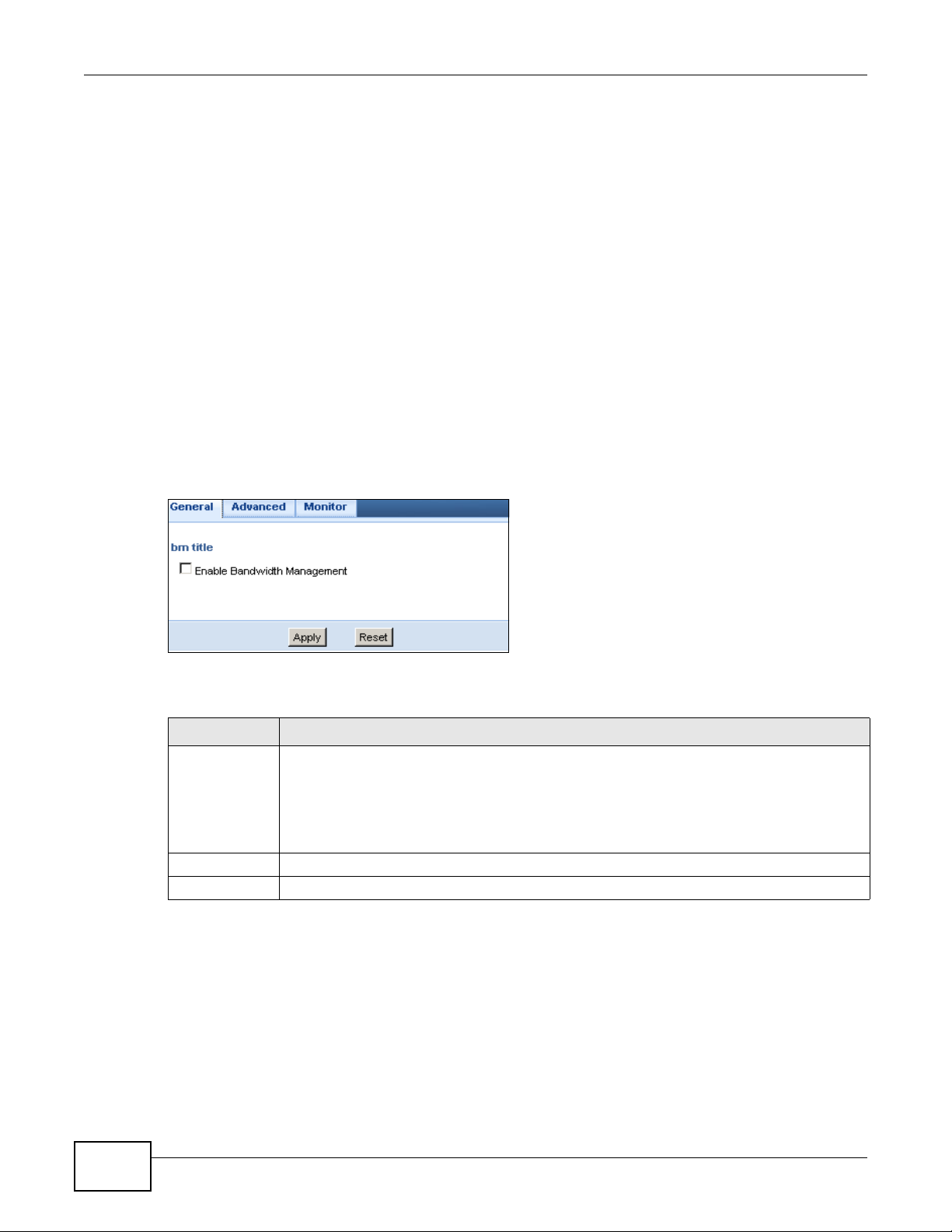
Figure 113 Management > Bandwidth Management > General
The following table describes the labels in this screen.
Table 71 Management > Bandwidth Management > General
LABEL DESCRIPTION
Enable
Bandwidth
Management
Apply Click Apply to save your customized settings.
Reset Click Reset to begin configuring this screen afresh.
This field allows you to have Router apply bandwidth management.
Enable bandwidth management to give traffic that matches a bandwidth rule priority over
traffic that does not match a bandwidth rule.
Enabling bandwidth management also allows you to control the maximum or minimum
amounts of bandwidth that can be used by traffic that matches a bandwidth rule.
23.5 Advanced Screen
Use this screen to configure bandwidth management rules for the pre-defined services or
applications.
You can also use this screen to configure bandwidth management rule for other services or
applications that are not on the pre-defined list of Router. Additionally, you can define the source
and destination IP addresses and port for a service or application.
164
NBG-419N v2 User’s Guide
Page 25
Chapter 23 Bandwidth Management
Note: The two tables shown in this screen can be configured and applied at the same
time.
Click Management > Bandwidth Management > Advanced to open the bandwidth
management Advanced screen.
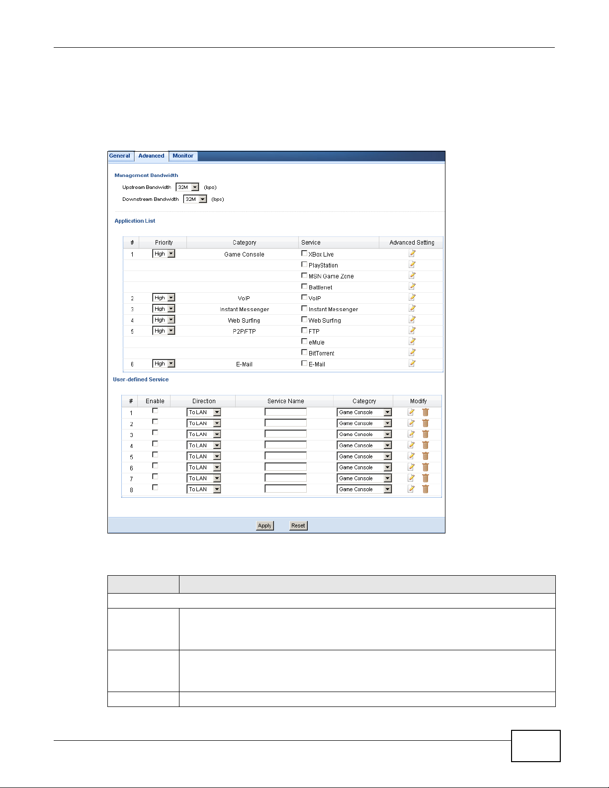
Figure 114 Management > Bandwidth Management > Advanced
The following table describes the labels in this screen.
Table 72 Management > Bandwidth Management > Advanced
LABEL DESCRIPTION
Management Bandwidth
Upstream
Bandwidth
Downstream
Bandwidth
Application List Use this table to allocate specific amounts of bandwidth based on a pre-defined service.
NBG-419N v2 User’s Guide
Select the total amount of bandwidth (from 64 Kilobits to 32 Megabits) that you want to
dedicate to uplink traffic.
This is traffic from LAN/WLAN to WAN.
Select the total amount of bandwidth (from 64 Kilobits to 32 Megabits) that you want to
dedicate to uplink traffic.
This is traffic from WAN to LAN/WLAN.
165
Page 26

Chapter 23 Bandwidth Management
Table 72 Management > Bandwidth Management > Advanced (continued)
LABEL DESCRIPTION
# This is the number of an individual bandwidth management rule.
Priority Select a priority from the drop down list box. Choose High, Mid or Low.
• High - Select this for voice traffic or video that is especially sensitive to jitter (jitter is
• Mid - Select this for "excellent effort" or better than best effort and would include
• Low - Select this for non-critical "background" traffic such as bulk transfers that are
Category This is the category where a service belongs.
Service This is the name of the service.
Select the check box to have the Router apply this bandwidth management rule.
Advanced
Setting
User-defined
Service
# This is the number of an individual bandwidth management rule.
Enable Select this check box to have the Router apply this bandwidth management rule.
Direction Select LAN to apply bandwidth management to traffic from WAN to LAN.
Click the Edit icon to open the Rule Configuration screen where you can modify the rule.
Use this table to allocate specific amounts of bandwidth to specific applications or services
you specify.
the variations in delay).
important business traffic that can tolerate some delay.
allowed but that should not affect other applications and users.
Select WAN to apply bandwidth management to traffic from LAN/WLAN to WAN.
Select WLAN to apply bandwidth management to traffic from WAN to WLAN.
Service Name Enter a descriptive name for the bandwidth management rule.
Category This is the category where a service belongs.
Modify Click the Edit icon to open the Rule Configuration screen. Modify an existing rule or
create a new rule in the Rule Configuration screen. See Section 23.5.2 on page 167 for
more information.
Click the Remove icon to delete a rule.
Apply Click Apply to save your customized settings.
Reset Click Reset to begin configuring this screen afresh.
23.5.1 Rule Configuration: Application Rule Configuration
If you want to edit a bandwidth management rule for a pre-defined service or application, click the
Edit icon in the Application List table of the Advanced screen. The following screen displays.
Figure 115 Bandwidth Management Rule Configuration: Application List
166
NBG-419N v2 User’s Guide
Page 27
Chapter 23 Bandwidth Management
The following table describes the labels in this screen.
Table 73 Bandwidth Management Rule Configuration: Application List
LABEL DESCRIPTION
# This is the number of an individual bandwidth management rule.
Enable Select an interface’s check box to enable bandwidth management on that interface.
Direction These read-only labels represent the physical interfaces. Bandwidth management applies to
all traffic flowing out of the router through the interface, regardless of the traffic’s source.
Traffic redirect or IP alias may cause LAN-to-LAN traffic to pass through the Router and be
managed by bandwidth management.
Bandwidth Select Maximum Bandwidth or Minimum Bandwidth and specify the maximum or
minimum bandwidth allowed for the rule in kilobits per second.
Destination Port This is the port number of the destination that define the traffic type, for example TCP port
80 defines web traffic.
See Appendix E on page 263 for some common services and port numbers.
Source Port This is the port number of the source that define the traffic type, for example TCP port 80
defines web traffic.
See Appendix E on page 263 for some common services and port numbers.
Protocol This is the protocol (TCP, UDP or user-defined) used for the service.
Apply Click Apply to save your customized settings.
Cancel Click Cancel to exit this screen without saving.
23.5.2 Rule Configuration: User Defined Service Rule Configuration
If you want to edit a bandwidth management rule for other applications or services, click the Edit
icon in the User-defined Service table of the Advanced screen. The following screen displays.
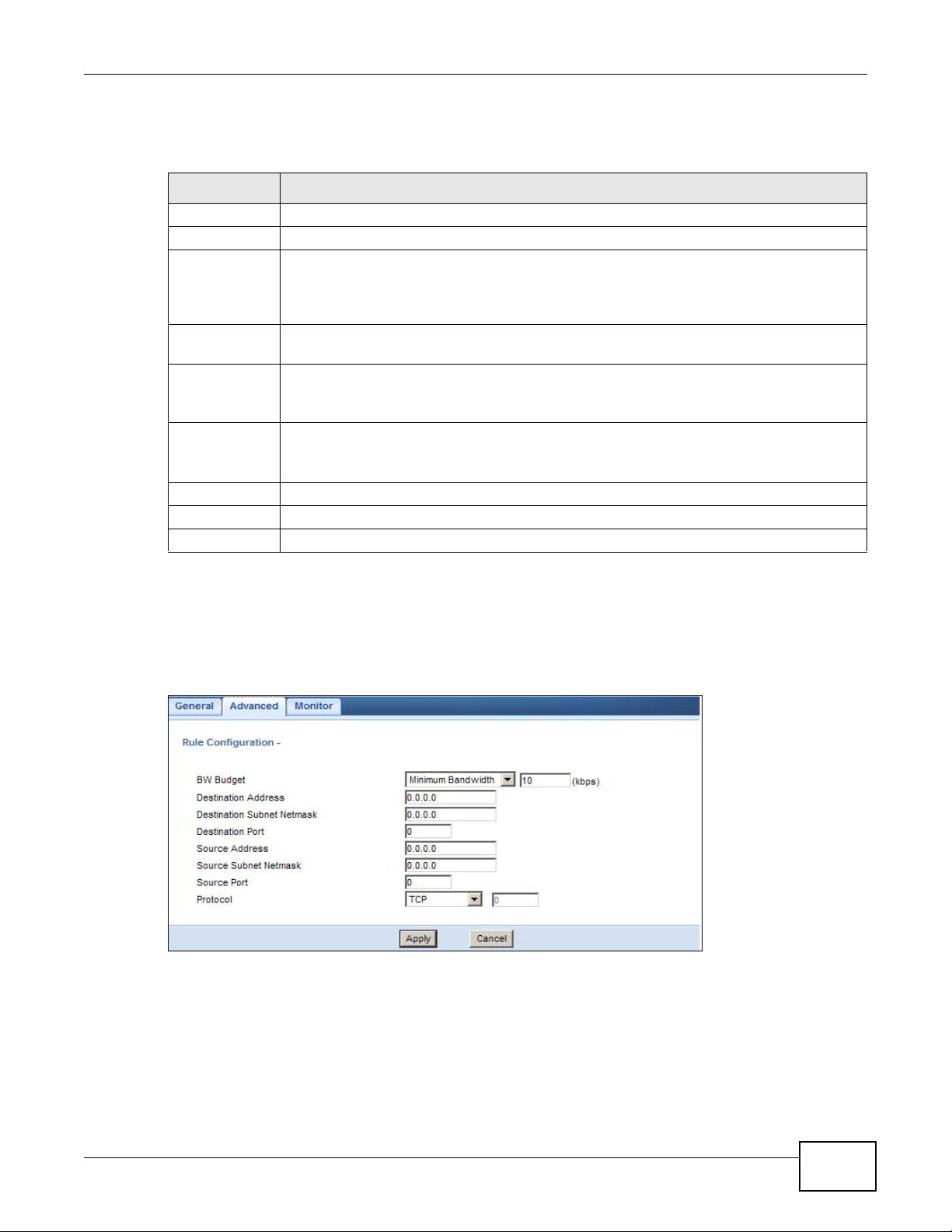
Figure 116 Bandwidth Management Rule Configuration: User-defined Service
The following table describes the labels in this screen
NBG-419N v2 User’s Guide
167
Page 28

Chapter 23 Bandwidth Management
Table 74 Bandwidth Management Rule Configuration: User-defined Service
LABEL DESCRIPTION
BW Budget Select Maximum Bandwidth or Minimum Bandwidth and specify the maximum or
Destination
Address
Destination
Subnet
Netmask
Destination
Port
Source Address Enter the IP address of the computer that initializes traffic for the application or service.
Source Subnet
Netmask
Source Port This is the port number of the source that define the traffic type, for example TCP port 80
Protocol Select the protocol (TCP, UDP, User defined) for which the bandwidth management rule
Apply Click Apply to save your customized settings.
Cancel Click Cancel to exit this screen without saving.
minimum bandwidth allowed for the rule in kilobits per second.
Enter the IP address of the destination computer.
The Router applies bandwidth management to the service or application that is entering this
computer.
Enter the subnet netmask of the destination of the traffic for which the bandwidth
management rule applies.
This is the port number of the destination that define the traffic type, for example TCP port
80 defines web traffic.
The Router applies bandwidth management to traffic initiating from this computer.
Enter the subnet netmask of the computer initiating the traffic for which the bandwidth
management rule applies.
defines web traffic.
applies.
If you select User-defined, enter the protocol for which the bandwidth management rule
applies. For example, ICMP for ping traffic.
See Appendix E on page 263 for commonly used services and port numbers.
23.6 Monitor Screen
Use this screen to view the amount of network bandwidth that applications running in the network
are using.
The bandwidth is measured in kilobits per second (kbps).
168
NBG-419N v2 User’s Guide
Page 29
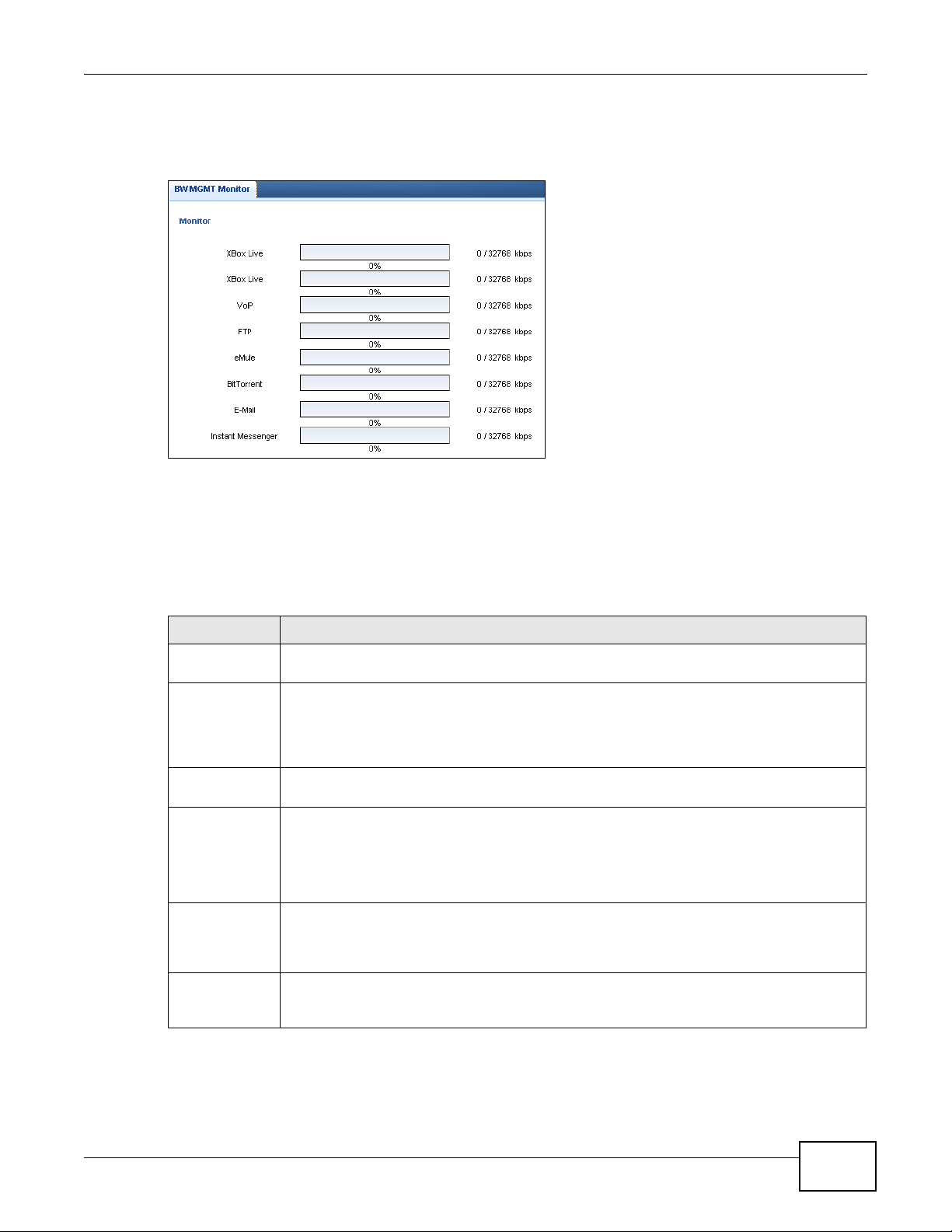
The monitor shows what kinds of applications are running in the network, the maximum kbps that
each application can use, as well as the percentage of bandwidth it is using.
Figure 117 Management > Bandwidth Management > Monitor
23.6.1 Predefined Bandwidth Management Services
Chapter 23 Bandwidth Management
The following is a description of some services that you can select and to which you can apply
media bandwidth management in the Management > Bandwidth Management > Advanced
screen.
Table 75 Media Bandwidth Management Setup: Services
SERVICE DESCRIPTION
FTP File Transfer Program enables fast transfer of files, including large files that may not be
WWW The World Wide Web (WWW) is an Internet system to distribute graphical, hyper-linked
E-Mail Electronic mail consists of messages sent through a computer network to specific groups or
VoIP (SIP) Sending voice signals over the Internet is called Voice over IP or VoIP. Session Initiated
BitTorrent BitTorrent is a free P2P (peer-to-peer) sharing tool allowing you to distribute large software
Gaming Online gaming services lets you play multiplayer games on the Internet via broadband
possible by e-mail.
information, based on Hyper Text Transfer Protocol (HTTP) - a client/server protocol for the
World Wide Web. The Web is not synonymous with the Internet; rather, it is just one service
on the Internet. Other services on the Internet include Internet Relay Chat and
Newsgroups. The Web is accessed through use of a browser.
individuals. Here are some default ports for e-mail:
Protocol (SIP) is an internationally recognized standard for implementing VoIP. SIP is an
application-layer control (signaling) protocol that handles the setting up, altering and
tearing down of voice and multimedia sessions over the Internet.
SIP is transported primarily over UDP but can also be transported over TCP.
and media files. BitTorrent requires you to search for a file with a searching engine yourself.
It distributes files by corporation and trading, that is, the client downloads the file in small
pieces and share the pieces with other peers to get other half of the file.
technology. As of this writing, your Router supports Xbox, Playstation, Battlenet and MSN
Game Zone.
NBG-419N v2 User’s Guide
169
Page 30

24.1 Overview
This chapter provides information on the Remote Management screens.
Remote Management allows you to manage your Router from a remote location through the
following interfaces:
•LAN and WAN
•LAN only
•WAN only
Note: The Router is managed using the Web Configurator.
CHAPTER 24
Remote Management
24.2 What You Can Do
Use the WWW screen (Section 24.4 on page 171) to define the interface/s from which the Router
can be managed remotely and specify a secure client that can manage the Router.
24.3 What You Need to Know
Remote management over LAN or WAN will not work when:
1 The IP address in the Secured Client IP Address field (Section 24.4 on page 171) does not
match the client IP address. If it does not match, the Router will disconnect the session
immediately.
2 There is already another remote management session. You may only have one remote
management session running at one time.
3 There is a firewall rule that blocks it.
24.3.1 Remote Management and NAT
When NAT is enabled:
• Use the Router’s WAN IP address when configuring from the WAN.
• Use the Router’s LAN IP address when configuring from the LAN.
NBG-419N v2 User’s Guide 170
Page 31

24.3.2 System Timeout
There is a default system management idle timeout of five minutes (three hundred seconds). The
Router automatically logs you out if the management session remains idle for longer than this
timeout period. The management session does not time out when a statistics screen is polling. You
can change the timeout period in the System screen
24.4 WWW Screen
To change your Router’s remote management settings, click Management > Remote
Management > WWW.
Figure 118 Management > Remote Management > WWW
Chapter 24 Remote Management
The following table describes the labels in this screen
Table 76 Management > Remote Management > WWW
LABEL DESCRIPTION
Server Port You may change the server port number for a service if needed, however you must use the
Server Access Select the interface(s) through which a computer may access the Router using this service.
Secured Client
IP Address
Apply Click Apply to save your customized settings and exit this screen.
Reset Click Reset to begin configuring this screen afresh.
same port number in order to use that service for remote management.
Select All to allow all computes to access the Router.
Otherwise, check Selected and specify the IP address of the computer that can access the
Router.
NBG-419N v2 User’s Guide
171
Page 32

Chapter 24 Remote Management
172
NBG-419N v2 User’s Guide
Page 33

Universal Plug-and-Play (UPnP)
25.1 Overview
This chapter introduces the UPnP feature in the web configurator.
Universal Plug and Play (UPnP) is a distributed, open networking standard that uses TCP/IP for
simple peer-to-peer network connectivity between devices. A UPnP device can dynamically join a
network, obtain an IP address, convey its capabilities and learn about other devices on the network.
In turn, a device can leave a network smoothly and automatically when it is no longer in use.
25.2 What You Can Do
Use the UPnP screen (Section 25.4 on page 174) to enable UPnP on your Router.
CHAPTER 25
25.3 What You Need to Know
UPnP hardware is identified as an icon in the Network Connections folder (Windows XP). Each UPnP
compatible device installed on your network will appear as a separate icon. Selecting the icon of a
UPnP device will allow you to access the information and properties of that device.
25.3.1 NAT Traversal
UPnP NAT traversal automates the process of allowing an application to operate through NAT. UPnP
network devices can automatically configure network addressing, announce their presence in the
network to other UPnP devices and enable exchange of simple product and service descriptions.
NAT traversal allows the following:
• Dynamic port mapping
• Learning public IP addresses
• Assigning lease times to mappings
Windows Messenger is an example of an application that supports NAT traversal and UPnP.
See the NAT chapter for more information on NAT.
NBG-419N v2 User’s Guide 173
Page 34

Chapter 25 Universal Plug-and-Pla y (UPn P)
25.3.2 Cautions with UPnP
The automated nature of NAT traversal applications in establishing their own services and opening
firewall ports may present network security issues. Network information and configuration may also
be obtained and modified by users in some network environments.
When a UPnP device joins a network, it announces its presence with a multicast message. For
security reasons, the Router allows multicast messages on the LAN only.
All UPnP-enabled devices may communicate freely with each other without additional configuration.
Disable UPnP if this is not your intention.
25.4 UPnP Screen
Use this screen to enable UPnP on your Router.
Click Management > UPnP to display the screen shown next.
Figure 119 Management > UPnP
The following table describes the fields in this screen.
Table 77 Management > UPnP
LABEL DESCRIPTION
Enable the
Universal Plug
and Play
(UPnP) Feature
Apply Click Apply to save the setting to the Router.
Reset Click Reset to return to the previously saved settings.
Select this check box to activate UPnP. Be aware that anyone could use a UPnP application
to open the web configurator's login screen without entering the Router's IP address
(although you must still enter the password to access the web configurator).
25.5 Technical Refereance
The sections show examples of using UPnP.
25.5.1 Using UPnP in Windows XP Example
This section shows you how to use the UPnP feature in Windows XP. You must already have UPnP
installed in Windows XP and UPnP activated on the Router.
174
NBG-419N v2 User’s Guide
Page 35

Chapter 25 Universal Plug-and-Play (UPnP)
Make sure the computer is connected to a LAN port of the Router. Turn on your computer and the
Router.
25.5.1.1 Auto-discover Your UPnP-enabled Network Device
1 Click start and Control Panel. Double-click Network Connections. An icon displays under
Internet Gateway.
2 Right-click the icon and select Properties.
Figure 120 Network Connections
3 In the Internet Connection Properties window, click Settings to see the port mappings there
were automatically created.
Figure 121 Internet Connection Properties
NBG-419N v2 User’s Guide
175
Page 36

Chapter 25 Universal Plug-and-Pla y (UPn P)
4 You may edit or delete the port mappings or click Add to manually add port mappings.
Figure 122 Internet Connection Properties: Advanced Settings
Figure 123 Internet Connection Properties: Advanced Settings: Add
Note: When the UPnP-enabled device is disconnected from your computer, all port
mappings will be deleted automatically.
5 Select Show icon in notification area when connected option and click OK. An icon displays in
the system tray.
Figure 124 System Tray Icon
176
NBG-419N v2 User’s Guide
Page 37

6 Double-click on the icon to display your current Internet connection status.
Figure 125 Internet Connection Status
25.5.2 Web Configurator Easy Access
With UPnP, you can access the web-based configurator on the Router without finding out the IP
address of the Router first. This comes helpful if you do not know the IP address of the Router.
Chapter 25 Universal Plug-and-Play (UPnP)
Follow the steps below to access the web configurator.
1 Click Start and then Control Panel.
2 Double-click Network Connections.
NBG-419N v2 User’s Guide
177
Page 38

Chapter 25 Universal Plug-and-Pla y (UPn P)
3 Select My Network Places under Other Places.
Figure 126 Network Connections
4 An icon with the description for each UPnP-enabled device displays under Local Network.
5 Right-click on the icon for your Router and select Invoke. The web configurator login screen
displays.
Figure 127 Network Connections: My Network Places
178
NBG-419N v2 User’s Guide
Page 39

Chapter 25 Universal Plug-and-Play (UPnP)
6 Right-click on the icon for your Router and select Properties. A properties window displays with
basic information about the Router.
Figure 128 Network Connections: My Network Places: Properties: Example
NBG-419N v2 User’s Guide
179
Page 40

Chapter 25 Universal Plug-and-Pla y (UPn P)
180
NBG-419N v2 User’s Guide
Page 41

26.1 Overview
This chapter provides information on the Maintenance screens.
26.2 What You Can Do
•Use the General screen to configure system and domain name. You can also set the timeout
period of the management session (Section 26.3 on page 181).
•Use the Password screen to change your Router’s system password (Section 26.4 on page 182).
•Use the Time screen to change your Router’s time and date (Section 26.5 on page 183).
•Use the Firmware Upgrade screen to upload firmware to your Router (Section 26.6 on page
184).
•Use the Backup/Restore screen to view information related to factory defaults, backup
configuration, and restoring configuration (Section 26.8 on page 187).
•Use the Reset/Restart screen to reboot the Router without turning the power off (Section 26.8
on page 187).
•Use the Sys OP Mode screen to select how you want to use your Router (Section 26.10 on page
189).
CHAPTER 26
Maintenance
26.3 General Screen
Use this screen to set the configure system and domain name as well as management session
timeout period. Click Maintenance > General. The following screen displays.
Figure 129 Maintenance > General
NBG-419N v2 User’s Guide 181
Page 42

Chapter 26 Maintenance
The following table describes the labels in this screen.
Table 78 Maintenance > General
LABEL DESCRIPTION
System Setup
System Name System Name is a unique name to identify the Router in an Ethernet network.
Domain Name Enter the domain name you want to give to the Router.
Administrator
Inactivity Timer
Apply Click Apply to save your changes back to the Router.
Cancel Click Cancel to begin configuring this screen afresh.
Type how many minutes a management session can be left idle before the
session times out. The default is 5 minutes. After it times out you have to log in
with your password again. Very long idle timeouts may have security risks. A
value of "0" means a management session never times out, no matter how long
it has been left idle (not recommended).
26.4 Password Screen
It is strongly recommended that you change your Router's password.
If you forget your Router's password (or IP address), you will need to reset the device. See Section
26.8 on page 187 for details.
Click Maintenance > Password. The screen appears as shown.
Figure 130 Maintenance > Password
The following table describes the labels in this screen.
Table 79 Maintenance > Password
LABEL DESCRIPTION
Password Setup Change your Router’s password (recommended) using the fields as shown.
Old Password Type the default password or the existing password you use to access the system in this
field.
New Password Type your new system password (up to 30 characters). Note that as you type a password,
the screen displays an asterisk (*) for each character you type.
Retype to
Confirm
Apply Click Apply to save your changes back to the Router.
Reset Click Reset to begin configuring this screen afresh.
Type the new password again in this field.
182
NBG-419N v2 User’s Guide
Page 43

26.5 Time Setting Screen
Use this screen to configure the Router’s time based on your local time zone. To change your
Router’s time and date, click Maintenance > Time. The screen appears as shown.
Figure 131 Maintenance > Time
Chapter 26 Maintenance
The following table describes the labels in this screen.
Table 80 Maintenance > Time
LABEL DESCRIPTION
Current Time and Date
Current Time This field displays the time of your Router.
Each time you reload this page, the Router synchronizes the time with the time server.
Current Date This field displays the date of your Router.
Each time you reload this page, the Router synchronizes the date with the time server.
Current Time and Date
Manual Select this radio button to enter the time and date manually. If you configure a new time
and date, Time Zone and Daylight Saving at the same time, the new time and date you
entered has priority and the Time Zone and Daylight Saving settings do not affect it.
New Time
(hh:mm:ss)
New Date
(yyyy/mm/dd)
This field displays the last updated time from the time server or the last time configured
manually.
When you select Manual, enter the new time in this field and then click Apply.
This field displays the last updated date from the time server or the last date configured
manually.
When you select Manual, enter the new date in this field and then click Apply.
NBG-419N v2 User’s Guide
183
Page 44

Chapter 26 Maintenance
Table 80 Maintenance > Time (continued)
LABEL DESCRIPTION
Get from Time
Server
Auto Select Auto to have the Router automatically search for an available time server and
User Defined Time
Server Address
Time Zone Setup
Time Zone Choose the time zone of your location. This will set the time difference between your time
Daylight Savings Daylight saving is a period from late spring to early fall when many countries set their
Start Date Configure the day and time when Daylight Saving Time starts if you selected Daylight
End Date Configure the day and time when Daylight Saving Time ends if you selected Daylight
Select this radio button to have the Router get the time and date from the time server
you specified below.
synchronize the date and time with the time server after you click Apply.
Select User Defined Time Server Address and enter the IP address or URL (up to 20
extended ASCII characters in length) of your time server. Check with your ISP/network
administrator if you are unsure of this information.
zone and Greenwich Mean Time (GMT).
clocks ahead of normal local time by one hour to give more daytime light in the evening.
Select this option if you use Daylight Saving Time.
Savings. The o'clock field uses the 24 hour format. Here are a couple of examples:
Daylight Saving Time starts in most parts of the United States on the first Sunday of
April. Each time zone in the United States starts using Daylight Saving Time at 2 A.M.
local time. So in the United States you would select First, Sunday, April and type 2 in
the o'clock field.
Daylight Saving Time starts in the European Union on the last Sunday of March. All of the
time zones in the European Union start using Daylight Saving Time at the same moment
(1 A.M. GMT or UTC). So in the European Union you would select Last, Sunday, March.
The time you type in the o'clock field depends on your time zone. In Germany for
instance, you would type 2 because Germany's time zone is one hour ahead of GMT or
UTC (GMT+1).
Savings. The o'clock field uses the 24 hour format. Here are a couple of examples:
Daylight Saving Time ends in the United States on the last Sunday of October. Each time
zone in the United States stops using Daylight Saving Time at 2 A.M. local time. So in the
United States you would select Last, Sunday, October and type 2 in the o'clock field.
Daylight Saving Time ends in the European Union on the last Sunday of October. All of the
time zones in the European Union stop using Daylight Saving Time at the same moment
(1 A.M. GMT or UTC). So in the European Union you would select Last, Sunday,
October. The time you type in the o'clock field depends on your time zone. In Germany
for instance, you would type 2 because Germany's time zone is one hour ahead of GMT or
UTC (GMT+1).
Apply Click Apply to save your changes back to the Router.
Cancel Click Cancel to begin configuring this screen afresh.
26.6 Firmware Upgrade Screen
Find firmware at www.zyxel.com in a file that (usually) uses the system model name with a “*.bin”
extension, e.g., “Router.bin”. The upload process uses HTTP (Hypertext Transfer Protocol) and may
take up to two minutes. After a successful upload, the system will reboot.
184
NBG-419N v2 User’s Guide
Page 45

Chapter 26 Maintenance
Click Maintenance > Firmware Upgrade. Follow the instructions in this screen to upload
firmware to your Router.
Figure 132 Maintenance > Firmware Upgrade
The following table describes the labels in this screen.
Table 81 Maintenance > Firmware Upgrade
LABEL DESCRIPTION
File Path Type in the location of the file you want to upload in this field or click Browse... to find it.
Browse... Click Browse... to find the .bin file you want to upload. Remember that you must
Upload Click Upload to begin the upload process. This process may take up to two minutes.
Check for
Latest
Firmware Now
decompress compressed (.zip) files before you can upload them.
Click this to check for the latest updated firmware.
Note: Do not turn off the Router while firmware upload is in progress!
After you see the Firmware Upload In Process screen, wait two minutes before logging into the
Router again.
The Router automatically restarts in this time causing a temporary network disconnect. In some
operating systems, you may see the following icon on your desktop.
Figure 133 Network Temporarily Disconnected
After two minutes, log in again and check your new firmware version in the Status screen.
If the upload was not successful, an error message appears. Click Return to go back to the
Firmware Upgrade screen.
NBG-419N v2 User’s Guide
185
Page 46

Chapter 26 Maintenance
26.7 Configuration Backup/Restore Screen
Backup configuration allows you to back up (save) the Router’s current configuration to a file on
your computer. Once your Router is configured and functioning properly, it is highly recommended
that you back up your configuration file before making configuration changes. The backup
configuration file will be useful in case you need to return to your previous settings.
Restore configuration allows you to upload a new or previously saved configuration file from your
computer to your Router.
Click Maintenance > Backup/Restore. Information related to factory defaults, backup
configuration, and restoring configuration appears as shown next.
Figure 134 Maintenance > Backup/Restore
186
The following table describes the labels in this screen.
Table 82 Maintenance > Backup/Restore
LABEL DESCRIPTION
Backup Click Backup to save the Router’s current configuration to your computer.
File Path Type in the location of the file you want to upload in this field or click Browse... to find it.
Browse... Click Browse... to find the file you want to upload. Remember that you must decompress
compressed (.ZIP) files before you can upload them.
NBG-419N v2 User’s Guide
Page 47

Chapter 26 Maintenance
Table 82 Maintenance > Backup/Restore (continued)
LABEL DESCRIPTION
Upload Click Upload to begin the upload process.
Note: Do not turn off the Router while configuration file upload is in progress.
After you see a “configuration upload successful” screen, you must then wait one minute
before logging into the Router again. The Router automatically restarts in this time causing
a temporary network disconnect.
If you see an error screen, click Back to return to the Backup/Restore screen.
Reset Pressing the Reset button in this section clears all user-entered configuration information
and returns the Router to its factory defaults.
You can also press the RESET button on the rear panel to reset the factory defaults of your
Router. Refer to the chapter about introducing the Web Configurator for more information
on the RESET button.
Note: If you uploaded the default configuration file you may need to change the IP
address of your computer to be in the same subnet as that of the default Router IP
address (192.168.1.2). See Appendix C on page 221 for details on how to set up
your computer’s IP address.
26.8 Reset/Restart Screen
System restart allows you to reboot the Router without turning the power off.
Click Maintenance > Reset/Restart to open the following screen.
Figure 135 Maintenance > Reset/Restart
Click Restart to have the Router reboot. This does not affect the Router's configuration.
26.9 System Operation Mode Overview
The Sys OP Mode (System Operation Mode) function lets you configure your Router as an access
point, wireless client or both at the same time. You can choose between Router, Access Point
Mode, and WISP Mode depending on your network topology and the features you require from
your device.
The following describes the device modes available in your Router.
NBG-419N v2 User’s Guide
187
Page 48

Chapter 26 Maintenance
Access Point
Wireless Client
Router
A router connects your local network with another network, such as the Internet. The router has
two IP addresses, the LAN IP address and the WAN IP address.
Figure 136 LAN and WAN IP Addresses in Router Mode
Access Point
An access point enabled all ethernet ports to be bridged together and be in the same subnet. To
connect to the Internet, another device, such as a router, is required.
Figure 137 Access Point Mode
WISP
A WISP client connects to an existing access point wirelessly. It acts just like a wireless client in
notebooks/computers.
Figure 138 IP Address in Access Point Mode
188
NBG-419N v2 User’s Guide
Page 49

26.10 Sys OP Mode Screen
Use this screen to select how you want to use your Router.
Figure 139 Maintenance > Sys OP Mode
Chapter 26 Maintenance
The following table describes the labels in the General screen.
Table 83 Maintenance > Sys OP Mode
LABEL DESCRIPTION
System Operation Mode
Router Select Router Mode if your device routes traffic between a local network and another
network such as the Internet. This mode offers services such as a firewall or bandwidth
management.
You can configure the IP address settings on your WAN port. Contact your ISP or system
administrator for more information on appropriate settings.
Access Point Select Access Point Mode if your device bridges traffic between clients on the same
WISP Mode Select WISP Mode if your device needs a wireless client to connect to an existing access
Apply Click Apply to save your settings.
Cancel Click Cancel to return your settings to the default (Router).
network.
•In Access Point Mode, all Ethernet ports have the same IP address.
• All ports on the rear panel of the device are LAN ports, including the port labeled WAN.
There is no WAN port.
• The DHCP server on your device is disabled.
• The IP address of the device on the local network is set to 192.168.1.2.
point.
• You cannot configure Wireless LAN settings (including WPS) and scheduling in the WISP
Mode.
• The IP address of the device on the local network is the same as the IP address given to
the Router while in router mode (default is 192.168.1.1).
Note: If you select the incorrect System Operation Mode you may not be able to connect
to the Internet.
NBG-419N v2 User’s Guide
189
Page 50

Chapter 26 Maintenance
190
NBG-419N v2 User’s Guide
Page 51

CHAPTER 27
Troubleshooting
This chapter offers some suggestions to solve problems you might encounter. The potential
problems are divided into the following categories.
• Power, Hardware Connections, and LEDs
• Router Access and Login
• Internet Access
• Resetting the Router to Its Factory Defaults
• Wireless Router/AP Troubleshooting
• ZyXEL Share Center Utility Problems
27.1 Power, Hardware Connections, and LEDs
The Router does not turn on. None of the LEDs turn on.
1 Make sure you are using the power adaptor or cord included with the Router.
2 Make sure the power adaptor or cord is connected to the Router and plugged in to an appropriate
power source. Make sure the power source is turned on.
3 Disconnect and re-connect the power adaptor or cord to the Router.
4 If the problem continues, contact the vendor.
One of the LEDs does not behave as expected.
1 Make sure you understand the normal behavior of the LED. See Section 1.5 on page 17.
2 Check the hardware connections. See the Quick Start Guide.
3 Inspect your cables for damage. Contact the vendor to replace any damaged cables.
4 Disconnect and re-connect the power adaptor to the Router.
5 If the problem continues, contact the vendor.
NBG-419N v2 User’s Guide 191
Page 52

Chapter 27 Troubleshooting
27.2 Router Access and Login
I don’t know the IP address of my Router.
1 The default IP address is 192.168.1.1.
2 If you changed the IP address and have forgotten it, you might get the IP address of the Router by
looking up the IP address of the default gateway for your computer. To do this in most Windows
computers, click Start > Run, enter cmd, and then enter ipconfig. The IP address of the Default
Gateway might be the IP address of the Router (it depends on the network), so enter this IP
address in your Internet browser.Set your device to Router Mode, login (see the Quick Start Guide
for instructions) and go to the Device Information table in the Status screen. Your Router’s IP
address is available in the Device Information table.
•If the DHCP setting under LAN information is None, your device has a fixed IP address.
•If the DHCP setting under LAN information is Client, then your device receives an IP
address from a DHCP server on the network.
3 If your Router is a DHCP client, you can find your IP address from the DHCP server. This information
is only available from the DHCP server which allocates IP addresses on your network. Find this
information directly from the DHCP server or contact your system administrator for more
information.
4 Reset your Router to change all settings back to their default. This means your current settings are
lost. See Section 27.4 on page 195 in the Troubleshooting for information on resetting your
Router.
I forgot the password.
1 The default password is 1234.
2 If this does not work, you have to reset the device to its factory defaults. See Section 27.4 on page
195.
I cannot see or access the Login screen in the Web Configurator.
1 Make sure you are using the correct IP address.
• The default IP address is 192.168.1.1.
• If you changed the IP address (Section 15.4 on page 135), use the new IP address.
• If you changed the IP address and have forgotten it, see the troubleshooting suggestions for I
don’t know the IP address of my Router.
192
NBG-419N v2 User’s Guide
Page 53

Chapter 27 Troubleshooting
2 Check the hardware connections, and make sure the LEDs are behaving as expected. See the Quick
Start Guide.
3 Make sure your Internet browser does not block pop-up windows and has JavaScript and Java
enabled. See Appendix A on page 199.
4 Make sure your computer is in the same subnet as the Router. (If you know that there are routers
between your computer and the Router, skip this step.)
• If there is a DHCP server on your network, make sure your computer is using a dynamic IP
address. See Appendix C on page 221.
• If there is no DHCP server on your network, make sure your computer’s IP address is in the
same subnet as the Router. See Appendix C on page 221.
5 Reset the device to its factory defaults, and try to access the Router with the default IP address.
See Section 5.3 on page 43.
6 If the problem continues, contact the network administrator or vendor, or try one of the advanced
suggestions.
Advanced Suggestion
• If your computer is connected to the WAN port or is connected wirelessly, use a computer that is
connected to a LAN/ETHERNET port.
I can see the Login screen, but I cannot log in to the Router.
1 Make sure you have entered the password correctly. The default password is 1234. This field is
case-sensitive, so make sure [Caps Lock] is not on.
2 This can happen when you fail to log out properly from your last session. Try logging in again after
5 minutes.
3 Disconnect and re-connect the power adaptor or cord to the Router.
4 If this does not work, you have to reset the device to its factory defaults. See Section 27.4 on page
195.
27.3 Internet Access
I cannot access the Internet.
1 Check the hardware connections, and make sure the LEDs are behaving as expected. See the Quick
Start Guide.
NBG-419N v2 User’s Guide
193
Page 54

Chapter 27 Troubleshooting
2 Make sure you entered your ISP account information correctly in the wizard. These fields are case-
sensitive, so make sure [Caps Lock] is not on.
3 If you are trying to access the Internet wirelessly, make sure the wireless settings in the wireless
client are the same as the settings in the AP.
•Go to Network > Wireless LAN > General > WDS and check if the Router is set to bridge
mode. Select Disable and try to connect to the Internet again.
4 Disconnect all the cables from your device, and follow the directions in the Quick Start Guide again.
5 Go to Maintenance > Sys OP Mode. Check your System Operation Mode setting.
•Select Router if your device routes traffic between a local network and another network such
as the Internet.
•Select Access Point if your device bridges traffic between clients on the same network.
6 If the problem continues, contact your ISP.
I cannot access the Internet anymore. I had access to the Internet (with the Router), but my
Internet connection is not available anymore.
1 Check the hardware connections, and make sure the LEDs are behaving as expected. See the Quick
Start Guide and Section 1.5 on page 17.
2 Reboot the Router.
3 If the problem continues, contact your ISP.
The Internet connection is slow or intermittent.
1 There might be a lot of traffic on the network. Look at the LEDs, and check Section 1.5 on page 17.
If the Router is sending or receiving a lot of information, try closing some programs that use the
Internet, especially peer-to-peer applications.
2 Check the signal strength. If the signal strength is low, try moving the Router closer to the AP if
possible, and look around to see if there are any devices that might be interfering with the wireless
network (for example, microwaves, other wireless networks, and so on).
3 Reboot the Router.
4 If the problem continues, contact the network administrator or vendor, or try one of the advanced
suggestions.
194
Advanced Suggestions
• Check the settings for bandwidth management. If it is disabled, you might consider activating it.
If it is enabled, you might consider changing the allocations.
NBG-419N v2 User’s Guide
Page 55

Chapter 27 Troubleshooting
• Check the settings for QoS. If it is disabled, you might consider activating it. If it is enabled, you
might consider raising or lowering the priority for some applications.
27.4 Resetting the Router to Its Factory Defaults
If you reset the Router, you lose all of the changes you have made. The Router re-loads its default
settings, and the password resets to 1234. You have to make all of your changes again.
You will lose all of your changes when you push the RESET button.
To reset the Router,
1 Make sure the power LED is on.
2 Press the RESET button for longer than 1 second to restart/reboot the Router.
3 Press the RESET button for longer than five seconds to set the Router back to its factory-default
configurations.
If the Router restarts automatically, wait for the Router to finish restarting, and log in to the Web
Configurator. The password is “1234”.
If the Router does not restart automatically, disconnect and reconnect the Router’s power. Then,
follow the directions above again.
27.5 Wireless Router/AP Troubleshooting
I cannot access the Router or ping any computer from the WLAN (wireless AP or router).
1 Make sure the wireless LAN is enabled on the Router
2 Make sure the wireless adapter on the wireless station is working properly.
3 Make sure the wireless adapter installed on your computer is IEEE 802.11 compatible and supports
the same wireless standard as the Router.
4 Make sure your computer (with a wireless adapter installed) is within the transmission range of the
Router.
5 Check that both the Router and your wireless station are using the same wireless and wireless
security settings.
6 Make sure traffic between the WLAN and the LAN is not blocked by the firewall on the Router.
NBG-419N v2 User’s Guide
195
Page 56

Chapter 27 Troubleshooting
7 Make sure you allow the Router to be remotely accessed through the WLAN interface. Check your
remote management settings.
• See the chapter on Wireless LAN in the User’s Guide for more information.
I set up URL keyword blocking, but I can still access a website that should be blocked.
Make sure that you select the Enable URL Keyword Blocking check box in the Content Filtering
screen. Make sure that the keywords that you type are listed in the Keyword List.
If a keyword that is listed in the Keyword List is not blocked when it is found in a URL, customize
the keyword blocking using commands. See the Customizing Keyword Blocking URL Checking
section in the Content Filter chapter.
I can access the Web Configurator after I switched to AP mode.
When you change from router mode to AP mode, your computer must have an IP address in the
range between “192.168.1.3” and “192.168.1.254”.
Refer to Appendix C on page 221 for instructions on how to change your computer’s IP address.
27.6 ZyXEL Share Center Utility Problems
I cannot access or see a USB device that is connected to the Router.
1 Disconnect the problematic USB device, then reconnect it to the Router.
2 Ensure that the USB device in question has power.
3 Check your cable connections.
4 Restart the Router by disconnecting the power and then reconnecting it.
5 If the USB device requires a special driver, install the driver from the installation disc that came
with the device. After driver installation, reconnect the USB device to the Router and try to connect
to it again with your computer.
6 If the problem persists, contact your vendor.
I cannot install the ZyXEL Share Center Utility.
196
NBG-419N v2 User’s Guide
Page 57

Chapter 27 Troubleshooting
1 Make sure that the set up program is one required for your operating system.
2 Install the latest patches and updates for your operating system.
3 Check the zyxel.com download site for a newer version of the utility.
Two computers cannot connect the USB storage at the same time using the ZyXEL Share
Center Utility.
Only one computer can connect to the USB storage through the ZyXEL Share Center Utlity at a
time. If two computers (A and B) want to connect to the USB storage by using the Utility, do the
following:
1 After A finishes connection to the USB storage, disconnect it by clicking Disconnect in A’s Utlity.
2 Connect B to the USB storage (through the Utility) by clicking Connect in B’s Utility.
3 If A does not disconnect the USB storage, B should click Request to Connect in the Utility to
request A to disconnect. B cannot access the USB storage until A disconnects.
•See Chapter 12 on page 89 for more details on connecting to USB storage by the Utility.
NBG-419N v2 User’s Guide
197
Page 58

Chapter 27 Troubleshooting
198
NBG-419N v2 User’s Guide
Page 59

Pop-up Windows, JavaScript and Java
In order to use the web configurator you need to allow:
• Web browser pop-up windows from your device.
• JavaScript (enabled by default).
• Java permissions (enabled by default).
Note: The screens used below belong to Internet Explorer version 6, 7 and 8. Screens for
other Internet Explorer versions may vary.
Internet Explorer Pop-up Blockers
You may have to disable pop-up blocking to log into your device.
APPENDIX A
Permissions
Either disable pop-up blocking (enabled by default in Windows XP SP (Service Pack) 2) or allow
pop-up blocking and create an exception for your device’s IP address.
Disable Pop-up Blockers
1 In Internet Explorer, select Tools, Pop-up Blocker and then select Turn Off Pop-up Blocker.
Figure 140 Pop-up Blocker
You can also check if pop-up blocking is disabled in the Pop-up Blocker section in the Privacy tab.
1 In Internet Explorer, select Tools, Internet Options, Privacy.
NBG-419N v2 User’s Guide 199
Page 60

Appendix A Pop-up Windows, JavaScript and Java Permissions
2 Clear the Block pop-ups check box in the Pop-up Blocker section of the screen. This disables any
web pop-up blockers you may have enabled.
Figure 141 Internet Options: Privacy
3 Click Apply to save this setting.
Enable Pop-up Blockers with Exceptions
Alternatively, if you only want to allow pop-up windows from your device, see the following steps.
1 In Internet Explorer, select Tools, Internet Options and then the Privacy tab.
200
NBG-419N v2 User’s Guide
Page 61

Appendix A Pop-up Windows, JavaScript and Java Permissions
2 Select Settings…to open the Pop-up Blocker Settings screen.
Figure 142 Internet Options: Privacy
3 Type the IP address of your device (the web page that you do not want to have blocked) with the
prefix “http://”. For example, http://192.168.167.1.
NBG-419N v2 User’s Guide
201
Page 62

Appendix A Pop-up Windows, JavaScript and Java Permissions
4 Click Add to move the IP address to the list of Allowed sites.
Figure 143 Pop-up Blocker Settings
5 Click Close to return to the Privacy screen.
6 Click Apply to save this setting.
JavaScript
If pages of the web configurator do not display properly in Internet Explorer, check that JavaScript
are allowed.
202
NBG-419N v2 User’s Guide
Page 63

Appendix A Pop-up Windows, JavaScript and Java Permissions
1 In Internet Explorer, click Tools, Internet Options and then the Security tab.
Figure 144 Internet Options: Security
2 Click the Custom Level... button.
3 Scroll down to Scripting.
4 Under Active scripting make sure that Enable is selected (the default).
5 Under Scripting of Java applets make sure that Enable is selected (the default).
NBG-419N v2 User’s Guide
203
Page 64

Appendix A Pop-up Windows, JavaScript and Java Permissions
6 Click OK to close the window.
Figure 145 Security Settings - Java Scripting
Java Permissions
1 From Internet Explorer, click Tools, Internet Options and then the Security tab.
2 Click the Custom Level... button.
3 Scroll down to Microsoft VM.
4 Under Java permissions make sure that a safety level is selected.
204
NBG-419N v2 User’s Guide
Page 65

5 Click OK to close the window.
Figure 146 Security Settings - Java
Appendix A Pop-up Windows, JavaScript and Java Permissions
JAVA (Sun)
1 From Internet Explorer, click Tools, Internet Options and then the Advanced tab.
2 Make sure that Use Java 2 for <applet> under Java (Sun) is selected.
NBG-419N v2 User’s Guide
205
Page 66

Appendix A Pop-up Windows, JavaScript and Java Permissions
3 Click OK to close the window.
Figure 147 Java (Sun)
Mozilla Firefox
Mozilla Firefox 2.0 screens are used here. Screens for other versions may vary slightly. The steps
below apply to Mozilla Firefox 3.0 as well.
You can enable Java, Javascript and pop-ups in one screen. Click Tools, then click Options in the
screen that appears.
Figure 148 Mozilla Firefox: TOOLS > Options
206
NBG-419N v2 User’s Guide
Page 67

Appendix A Pop-up Windows, JavaScript and Java Permissions
Click Content to show the screen below. Select the check boxes as shown in the following screen.
Figure 149 Mozilla Firefox Content Security
Opera
Opera 10 screens are used here. Screens for other versions may vary slightly.
NBG-419N v2 User’s Guide
207
Page 68

Appendix A Pop-up Windows, JavaScript and Java Permissions
Allowing Pop-Ups
From Opera, click Tools, then Preferences. In the General tab, go to Choose how you prefer
to handle pop-ups and select Open all pop-ups.
Figure 150 Opera: Allowing Pop-Ups
Enabling Java
From Opera, click Tools, then Preferences. In the Advanced tab, select Content from the leftside menu. Select the check boxes as shown in the following screen.
Figure 151 Opera: Enabling Java
208
NBG-419N v2 User’s Guide
Page 69

Appendix A Pop-up Windows, JavaScript and Java Permissions
To customize JavaScript behavior in the Opera browser, click JavaScript Options.
Figure 152 Opera: JavaScript Options
Select the items you want Opera’s JavaScript to apply.
NBG-419N v2 User’s Guide
209
Page 70

Appendix A Pop-up Windows, JavaScript and Java Permissions
210
NBG-419N v2 User’s Guide
Page 71

This appendix introduces IP addresses and subnet masks.
IP addresses identify individual devices on a network. Every networking device (including
computers, servers, routers, printers, etc.) needs an IP address to communicate across the
network. These networking devices are also known as hosts.
Subnet masks determine the maximum number of possible hosts on a network. You can also use
subnet masks to divide one network into multiple sub-networks.
Introduction to IP Addresses
One part of the IP address is the network number, and the other part is the host ID. In the same
way that houses on a street share a common street name, the hosts on a network share a common
network number. Similarly, as each house has its own house number, each host on the network has
its own unique identifying number - the host ID. Routers use the network number to send packets
to the correct network, while the host ID determines to which host on the network the packets are
delivered.
APPENDIX B
IP Addresses and Subnetting
Structure
An IP address is made up of four parts, written in dotted decimal notation (for example,
192.168.1.1). Each of these four parts is known as an octet. An octet is an eight-digit binary
number (for example 11000000, which is 192 in decimal notation).
Therefore, each octet has a possible range of 00000000 to 11111111 in binary, or 0 to 255 in
decimal.
NBG-419N v2 User’s Guide 211
Page 72

Appendix B IP Addresses and Subnetting
The following figure shows an example IP address in which the first three octets (192.168.1) are
the network number, and the fourth octet (16) is the host ID.
Figure 153 Network Number and Host ID
How much of the IP address is the network number and how much is the host ID varies according
to the subnet mask.
Subnet Masks
A subnet mask is used to determine which bits are part of the network number, and which bits are
part of the host ID (using a logical AND operation). The term “subnet” is short for “sub-network”.
A subnet mask has 32 bits. If a bit in the subnet mask is a “1” then the corresponding bit in the IP
address is part of the network number. If a bit in the subnet mask is “0” then the corresponding bit
in the IP address is part of the host ID.
The following example shows a subnet mask identifying the network number (in bold text) and host
ID of an IP address (192.168.1.2 in decimal).
Table 84 IP Address Network Number and Host ID Example
IP Address (Binary) 11000000 10101000 00000001 00000010
Subnet Mask (Binary) 11111111 11111111 11111111 00000000
Network Number 11000000 10101000 00000001
Host ID 00000010
1ST OCTET:
(192)
2ND
OCTET:
(168)
3RD
OCTET:
(1)
4TH OCTET
(2)
212
By convention, subnet masks always consist of a continuous sequence of ones beginning from the
leftmost bit of the mask, followed by a continuous sequence of zeros, for a total number of 32 bits.
Subnet masks can be referred to by the size of the network number part (the bits with a “1” value).
For example, an “8-bit mask” means that the first 8 bits of the mask are ones and the remaining 24
bits are zeroes.
NBG-419N v2 User’s Guide
Page 73

Subnet masks are expressed in dotted decimal notation just like IP addresses. The following
examples show the binary and decimal notation for 8-bit, 16-bit, 24-bit and 29-bit subnet masks.
Table 85 Subnet Masks
8-bit mask 11111111 00000000 00000000 00000000 255.0.0.0
16-bit mask 11111111 11111111 00000000 00000000 255.255.0.0
24-bit mask 11111111 11111111 11111111 00000000 255.255.255.0
29-bit mask 11111111 11111111 11111111 11111000 255.255.255.248
Network Size
The size of the network number determines the maximum number of possible hosts you can have
on your network. The larger the number of network number bits, the smaller the number of
remaining host ID bits.
An IP address with host IDs of all zeros is the IP address of the network (192.168.1.0 with a 24-bit
subnet mask, for example). An IP address with host IDs of all ones is the broadcast address for that
network (192.168.1.255 with a 24-bit subnet mask, for example).
BINARY
1ST
OCTET
2ND
OCTET
3RD
OCTET
Appendix B IP Addresses and Subnetting
DECIMAL
4TH OCTET
Notation
As these two IP addresses cannot be used for individual hosts, calculate the maximum number of
possible hosts in a network as follows:
Table 86 Maximum Host Numbers
SUBNET MASK HOST ID SIZE
8 bits 255.0.0.0 24 bits 224 – 2 16777214
16
16 bits 255.255.0.0 16 bits 2
24 bits 255.255.255.0 8 bits 2
29 bits 255.255.255.248 3 bits 2
– 2 65534
8
– 2 254
3
– 2 6
MAXIMUM NUMBER OF
HOSTS
Since the mask is always a continuous number of ones beginning from the left, followed by a
continuous number of zeros for the remainder of the 32 bit mask, you can simply specify the
number of ones instead of writing the value of each octet. This is usually specified by writing a “/”
followed by the number of bits in the mask after the address.
For example, 192.1.1.0 /25 is equivalent to saying 192.1.1.0 with subnet mask 255.255.255.128.
The following table shows some possible subnet masks using both notations.
Table 87 Alternative Subnet Mask Notation
SUBNET MASK
255.255.255.0 /24 0000 0000 0
255.255.255.128 /25 1000 0000 128
255.255.255.192 /26 1100 0000 192
ALTERNATIVE
NOTATION
LAST OCTET
(BINARY)
LAST OCTET
(DECIMAL)
NBG-419N v2 User’s Guide
213
Page 74

Appendix B IP Addresses and Subnetting
Table 87 Alternative Subnet Mask Notation (continued)
SUBNET MASK
255.255.255.224 /27 1110 0000 224
255.255.255.240 /28 1111 0000 240
255.255.255.248 /29 1111 1000 248
255.255.255.252 /30 1111 1100 252
ALTERNATIVE
NOTATION
Subnetting
You can use subnetting to divide one network into multiple sub-networks. In the following example
a network administrator creates two sub-networks to isolate a group of servers from the rest of the
company network for security reasons.
In this example, the company network address is 192.168.1.0. The first three octets of the address
(192.168.1) are the network number, and the remaining octet is the host ID, allowing a maximum
8
of 2
– 2 or 254 possible hosts.
The following figure shows the company network before subnetting.
LAST OCTET
(BINARY)
LAST OCTET
(DECIMAL)
Figure 154 Subnetting Example: Before Subnetting
You can “borrow” one of the host ID bits to divide the network 192.168.1.0 into two separate subnetworks. The subnet mask is now 25 bits (255.255.255.128 or /25).
The “borrowed” host ID bit can have a value of either 0 or 1, allowing two subnets; 192.168.1.0 /25
and 192.168.1.128 /25.
214
NBG-419N v2 User’s Guide
Page 75

Appendix B IP Addresses and Subnetting
The following figure shows the company network after subnetting. There are now two subnetworks, A and B.
Figure 155 Subnetting Example: After Subnetting
In a 25-bit subnet the host ID has 7 bits, so each sub-network has a maximum of 2
possible hosts (a host ID of all zeroes is the subnet’s address itself, all ones is the subnet’s
broadcast address).
192.168.1.0 with mask 255.255.255.128 is subnet A itself, and 192.168.1.127 with mask
255.255.255.128 is its broadcast address. Therefore, the lowest IP address that can be assigned to
an actual host for subnet A is 192.168.1.1 and the highest is 192.168.1.126.
Similarly, the host ID range for subnet B is 192.168.1.129 to 192.168.1.254.
Example: Four Subnets
The previous example illustrated using a 25-bit subnet mask to divide a 24-bit address into two
subnets. Similarly, to divide a 24-bit address into four subnets, you need to “borrow” two host ID
bits to give four possible combinations (00, 01, 10 and 11). The subnet mask is 26 bits
(11111111.11111111.11111111.11000000) or 255.255.255.192.
Each subnet contains 6 host ID bits, giving 2
zeroes is the subnet itself, all ones is the subnet’s broadcast address).
Table 88 Subnet 1
IP/SUBNET MASK NETWORK NUMBER
IP Address (Decimal) 192.168.1. 0
IP Address (Binary) 11000000.10101000.00000001. 00000000
Subnet Mask (Binary) 11111111.11111111.11111111. 11000000
7
– 2 or 126
6
- 2 or 62 hosts for each subnet (a host ID of all
LAST OCTET BIT
VALUE
NBG-419N v2 User’s Guide
215
Page 76

Appendix B IP Addresses and Subnetting
Table 88 Subnet 1 (continued)
IP/SUBNET MASK NETWORK NUMBER
Subnet Address:
192.168.1.0
Broadcast Address:
192.168.1.63
Table 89 Subnet 2
IP/SUBNET MASK NETWORK NUMBER
IP Address 192.168.1. 64
IP Address (Binary) 11000000.10101000.00000001. 01000000
Subnet Mask (Binary) 11111111.11111111.11111111. 11000000
Subnet Address:
192.168.1.64
Broadcast Address:
192.168.1.127
Table 90 Subnet 3
IP/SUBNET MASK NETWORK NUMBER
IP Address 192.168.1. 128
IP Address (Binary) 11000000.10101000.00000001. 10000000
Subnet Mask (Binary) 11111111.11111111.11111111. 11000000
Subnet Address:
192.168.1.128
Broadcast Address:
192.168.1.191
LAST OCTET BIT
VALUE
Lowest Host ID: 192.168.1.1
Highest Host ID: 192.168.1.62
LAST OCTET BIT
VALUE
Lowest Host ID: 192.168.1.65
Highest Host ID: 192.168.1.126
LAST OCTET BIT
VALUE
Lowest Host ID: 192.168.1.129
Highest Host ID: 192.168.1.190
Table 91 Subnet 4
IP/SUBNET MASK NETWORK NUMBER
IP Address 192.168.1. 192
IP Address (Binary) 11000000.10101000.00000001. 11000000
Subnet Mask (Binary) 11111111.11111111.11111111. 11000000
Subnet Address:
192.168.1.192
Broadcast Address:
192.168.1.255
Example: Eight Subnets
Similarly, use a 27-bit mask to create eight subnets (000, 001, 010, 011, 100, 101, 110 and 111).
LAST OCTET BIT
VALUE
Lowest Host ID: 192.168.1.193
Highest Host ID: 192.168.1.254
216
NBG-419N v2 User’s Guide
Page 77

The following table shows IP address last octet values for each subnet.
Table 92 Eight Subnets
SUBNET
1 0 1 30 31
2 32 33 62 63
3 64 65 94 95
4 96 97 126 127
5 128 129 158 159
6 160 161 190 191
7 192 193 222 223
8 224 225 254 255
Subnet Planning
The following table is a summary for subnet planning on a network with a 24-bit network number.
Table 93 24-bit Network Number Subnet Planning
NO. “BORROWED”
HOST BITS
1 255.255.255.128 (/25) 2 126
2 255.255.255.192 (/26) 4 62
3 255.255.255.224 (/27) 8 30
4 255.255.255.240 (/28) 16 14
5 255.255.255.248 (/29) 32 6
6 255.255.255.252 (/30) 64 2
7 255.255.255.254 (/31) 128 1
SUBNET
ADDRESS
FIRST ADDRESS
LAST
ADDRESS
SUBNET MASK NO. SUBNETS
Appendix B IP Addresses and Subnetting
BROADCAST
ADDRESS
NO. HOSTS PER
SUBNET
The following table is a summary for subnet planning on a network with a 16-bit network number.
Table 94 16-bit Network Number Subnet Planning
NO. “BORROWED”
HOST BITS
1 255.255.128.0 (/17) 2 32766
2 255.255.192.0 (/18) 4 16382
3 255.255.224.0 (/19) 8 8190
4 255.255.240.0 (/20) 16 4094
5 255.255.248.0 (/21) 32 2046
6 255.255.252.0 (/22) 64 1022
7 255.255.254.0 (/23) 128 510
8 255.255.255.0 (/24) 256 254
9 255.255.255.128 (/25) 512 126
10 255.255.255.192 (/26) 1024 62
11 255.255.255.224 (/27) 2048 30
12 255.255.255.240 (/28) 4096 14
NBG-419N v2 User’s Guide
SUBNET MASK NO. SUBNETS
NO. HOSTS PER
SUBNET
217
Page 78

Appendix B IP Addresses and Subnetting
Table 94 16-bit Network Number Subnet Planning (continued)
NO. “BORROWED”
HOST BITS
13 255.255.255.248 (/29) 8192 6
14 255.255.255.252 (/30) 16384 2
15 255.255.255.254 (/31) 32768 1
Configuring IP Addresses
Where you obtain your network number depends on your particular situation. If the ISP or your
network administrator assigns you a block of registered IP addresses, follow their instructions in
selecting the IP addresses and the subnet mask.
If the ISP did not explicitly give you an IP network number, then most likely you have a single user
account and the ISP will assign you a dynamic IP address when the connection is established. If this
is the case, it is recommended that you select a network number from 192.168.0.0 to
192.168.255.0. The Internet Assigned Number Authority (IANA) reserved this block of addresses
specifically for private use; please do not use any other number unless you are told otherwise. You
must also enable Network Address Translation (NAT) on the Router.
SUBNET MASK NO. SUBNETS
NO. HOSTS PER
SUBNET
Once you have decided on the network number, pick an IP address for your Router that is easy to
remember (for instance, 192.168.1.1) but make sure that no other device on your network is using
that IP address.
The subnet mask specifies the network number portion of an IP address. Your Router will compute
the subnet mask automatically based on the IP address that you entered. You don't need to change
the subnet mask computed by the Router unless you are instructed to do otherwise.
Private IP Addresses
Every machine on the Internet must have a unique address. If your networks are isolated from the
Internet (running only between two branch offices, for example) you can assign any IP addresses to
the hosts without problems. However, the Internet Assigned Numbers Authority (IANA) has
reserved the following three blocks of IP addresses specifically for private networks:
• 10.0.0.0 — 10.255.255.255
• 172.16.0.0 — 172.31.255.255
• 192.168.0.0 — 192.168.255.255
You can obtain your IP address from the IANA, from an ISP, or it can be assigned from a private
network. If you belong to a small organization and your Internet access is through an ISP, the ISP
can provide you with the Internet addresses for your local networks. On the other hand, if you are
part of a much larger organization, you should consult your network administrator for the
appropriate IP addresses.
218
Regardless of your particular situation, do not create an arbitrary IP address; always follow the
guidelines above. For more information on address assignment, please refer to RFC 1597, Address
Allocation for Private Internets and RFC 1466, Guidelines for Management of IP Address Space.
NBG-419N v2 User’s Guide
Page 79

IP Address Conflicts
Each device on a network must have a unique IP address. Devices with duplicate IP addresses on
the same network will not be able to access the Internet or other resources. The devices may also
be unreachable through the network.
Conflicting Computer IP Addresses Example
More than one device can not use the same IP address. In the following example computer A has a
static (or fixed) IP address that is the same as the IP address that a DHCP server assigns to
computer B which is a DHCP client. Neither can access the Internet. This problem can be solved by
assigning a different static IP address to computer A or setting computer A to obtain an IP address
automatically.
Figure 156 Conflicting Computer IP Addresses Example
Appendix B IP Addresses and Subnetting
Conflicting Router IP Addresses Example
Since a router connects different networks, it must have interfaces using different network
numbers. For example, if a router is set between a LAN and the Internet (WAN), the router’s LAN
and WAN addresses must be on different subnets. In the following example, the LAN and WAN are
on the same subnet. The LAN computers cannot access the Internet because the router cannot
route between networks.
Figure 157 Conflicting Router IP Addresses Example
NBG-419N v2 User’s Guide
219
Page 80

Appendix B IP Addresses and Subnetting
Conflicting Computer and Router IP Addresses Example
More than one device can not use the same IP address. In the following example, the computer and
the router’s LAN port both use 192.168.1.1 as the IP address. The computer cannot access the
Internet. This problem can be solved by assigning a different IP address to the computer or the
router’s LAN port.
Figure 158 Conflicting Computer and Router IP Addresses Example
220
NBG-419N v2 User’s Guide
Page 81

APPENDIX C
Setting Up Your Computer’s IP Address
Note: Your specific Router may not support all of the operating systems described in this
appendix. See the product specifications for more information about which
operating systems are supported.
This appendix shows you how to configure the IP settings on your computer in order for it to be
able to communicate with the other devices on your network. Windows Vista/XP/2000, Mac OS 9/
OS X, and all versions of UNIX/LINUX include the software components you need to use TCP/IP on
your computer.
If you manually assign IP information instead of using a dynamic IP, make sure that your network’s
computers have IP addresses that place them in the same subnet.
In this appendix, you can set up an IP address for:
• Windows XP/NT/2000 on page 222
• Windows Vista on page 225
• Windows 7 on page 229
• Mac OS X: 10.3 and 10.4 on page 233
• Mac OS X: 10.5 and 10.6 on page 236
• Linux: Ubuntu 8 (GNOME) on page 239
• Linux: openSUSE 10.3 (KDE) on page 243
NBG-419N v2 User’s Guide 221
Page 82

Appendix C Setting Up Your Computer’s IP Address
Windows XP/NT/2000
The following example uses the default Windows XP display theme but can also apply to Windows
2000 and Windows NT.
1 Click Start > Control Panel.
2 In the Control Panel, click the Network Connections icon.
222
NBG-419N v2 User’s Guide
Page 83

Appendix C Setting Up Your Computer’s IP Address
3 Right-click Local Area Connection and then select Properties.
4 On the General tab, select Internet Protocol (TCP/IP) and then click Properties.
NBG-419N v2 User’s Guide
223
Page 84

Appendix C Setting Up Your Computer’s IP Address
5 The Internet Protocol TCP/IP Properties window opens.
6 Select Obtain an IP address automatically if your network administrator or ISP assigns your IP
address dynamically.
Select Use the following IP Address and fill in the IP address, Subnet mask, and Default
gateway fields if you have a static IP address that was assigned to you by your network
administrator or ISP. You may also have to enter a Preferred DNS server and an Alternate DNS
server, if that information was provided.
7 Click OK to close the Internet Protocol (TCP/IP) Properties window.
8 Click OK to close the Local Area Connection Properties window.
Verifying Settings
1 Click Start > All Programs > Accessories > Command Prompt.
2 In the Command Prompt window, type "ipconfig" and then press [ENTER].
You can also go to Start > Control Panel > Network Connections, right-click a network
connection, click Status and then click the Support tab to view your IP address and connection
information.
224
NBG-419N v2 User’s Guide
Page 85

Windows Vista
This section shows screens from Windows Vista Professional.
1 Click Start > Control Panel.
2 In the Control Panel, click the Network and Internet icon.
Appendix C Setting Up Your Computer’s IP Address
3 Click the Network and Sharing Center icon.
NBG-419N v2 User’s Guide
225
Page 86

Appendix C Setting Up Your Computer’s IP Address
4 Click Manage network connections.
5 Right-click Local Area Connection and then select Properties.
Note: During this procedure, click Continue whenever Windows displays a screen saying
that it needs your permission to continue.
226
NBG-419N v2 User’s Guide
Page 87

Appendix C Setting Up Your Computer’s IP Address
6 Select Internet Protocol Version 4 (TCP/IPv4) and then select Properties.
NBG-419N v2 User’s Guide
227
Page 88

Appendix C Setting Up Your Computer’s IP Address
7 The Internet Protocol Version 4 (TCP/IPv4) Properties window opens.
8 Select Obtain an IP address automatically if your network administrator or ISP assigns your IP
address dynamically.
Select Use the following IP Address and fill in the IP address, Subnet mask, and Default
gateway fields if you have a static IP address that was assigned to you by your network
administrator or ISP. You may also have to enter a Preferred DNS server and an Alternate DNS
server, if that information was provided.Click Advanced.
9 Click OK to close the Internet Protocol (TCP/IP) Properties window.
10 Click OK to close the Local Area Connection Properties window.
Verifying Settings
1 Click Start > All Programs > Accessories > Command Prompt.
2 In the Command Prompt window, type "ipconfig" and then press [ENTER].
You can also go to Start > Control Panel > Network Connections, right-click a network
connection, click Status and then click the Support tab to view your IP address and connection
information.
228
NBG-419N v2 User’s Guide
Page 89

Windows 7
This section shows screens from Windows 7 Enterprise.
1 Click Start > Control Panel.
2 In the Control Panel, click View network status and tasks under the Network and Internet
category.
Appendix C Setting Up Your Computer’s IP Address
3 Click Change adapter settings.
NBG-419N v2 User’s Guide
229
Page 90

Appendix C Setting Up Your Computer’s IP Address
4 Double click Local Area Connection and then select Properties.
Note: During this procedure, click Continue whenever Windows displays a screen saying
that it needs your permission to continue.
230
NBG-419N v2 User’s Guide
Page 91

Appendix C Setting Up Your Computer’s IP Address
5 Select Internet Protocol Version 4 (TCP/IPv4) and then select Properties.
NBG-419N v2 User’s Guide
231
Page 92

Appendix C Setting Up Your Computer’s IP Address
6 The Internet Protocol Version 4 (TCP/IPv4) Properties window opens.
7 Select Obtain an IP address automatically if your network administrator or ISP assigns your IP
address dynamically.
Select Use the following IP Address and fill in the IP address, Subnet mask, and Default
gateway fields if you have a static IP address that was assigned to you by your network
administrator or ISP. You may also have to enter a Preferred DNS server and an Alternate DNS
server, if that information was provided. Click Advanced if you want to configure advanced
settings for IP, DNS and WINS.
8 Click OK to close the Internet Protocol (TCP/IP) Properties window.
9 Click OK to close the Local Area Connection Properties window.
232
NBG-419N v2 User’s Guide
Page 93

Verifying Settings
1 Click Start > All Programs > Accessories > Command Prompt.
2 In the Command Prompt window, type "ipconfig" and then press [ENTER].
3 The IP settings are displayed as follows.
Appendix C Setting Up Your Computer’s IP Address
Mac OS X: 10.3 and 10.4
The screens in this section are from Mac OS X 10.4 but can also apply to 10.3.
1 Click Apple > System Preferences.
NBG-419N v2 User’s Guide
233
Page 94

Appendix C Setting Up Your Computer’s IP Address
2 In the System Preferences window, click the Network icon.
3 When the Network preferences pane opens, select Built-in Ethernet from the network
connection type list, and then click Configure.
234
NBG-419N v2 User’s Guide
Page 95

Appendix C Setting Up Your Computer’s IP Address
4 For dynamically assigned settings, select Using DHCP from the Configure IPv4 list in the TCP/IP
tab.
5 For statically assigned settings, do the following:
•From the Configure IPv4 list, select Manually.
•In the IP Address field, type your IP address.
•In the Subnet Mask field, type your subnet mask.
•In the Router field, type the IP address of your device.
6 Click Apply Now and close the window.
NBG-419N v2 User’s Guide
235
Page 96

Appendix C Setting Up Your Computer’s IP Address
Verifying Settings
Check your TCP/IP properties by clicking Applications > Utilities > Network Utilities, and then
selecting the appropriate Network Interface from the Info tab.
Figure 159 Mac OS X 10.4: Network Utility
Mac OS X: 10.5 and 10.6
The screens in this section are from Mac OS X 10.5 but can also apply to 10.6.
1 Click Apple > System Preferences.
236
NBG-419N v2 User’s Guide
Page 97

2 In System Preferences, click the Network icon.
Appendix C Setting Up Your Computer’s IP Address
3 When the Network preferences pane opens, select Ethernet from the list of available connection
types.
4 From the Configure list, select Using DHCP for dynamically assigned settings.
NBG-419N v2 User’s Guide
237
Page 98

Appendix C Setting Up Your Computer’s IP Address
5 For statically assigned settings, do the following:
•From the Configure list, select Manually.
•In the IP Address field, enter your IP address.
•In the Subnet Mask field, enter your subnet mask.
•In the Router field, enter the IP address of your Router.
6 Click Apply and close the window.
238
NBG-419N v2 User’s Guide
Page 99

Verifying Settings
Check your TCP/IP properties by clicking Applications > Utilities > Network Utilities, and then
selecting the appropriate Network interface from the Info tab.
Figure 160 Mac OS X 10.5: Network Utility
Appendix C Setting Up Your Computer’s IP Address
Linux: Ubuntu 8 (GNOME)
This section shows you how to configure your computer’s TCP/IP settings in the GNU Object Model
Environment (GNOME) using the Ubuntu 8 Linux distribution. The procedure, screens and file
locations may vary depending on your specific distribution, release version, and individual
configuration. The following screens use the default Ubuntu 8 installation.
Note: Make sure you are logged in as the root administrator.
Follow the steps below to configure your computer IP address in GNOME:
1 Click System > Administration > Network.
NBG-419N v2 User’s Guide
239
Page 100

Appendix C Setting Up Your Computer’s IP Address
2 When the Network Settings window opens, click Unlock to open the Authenticate window. (By
default, the Unlock button is greyed out until clicked.) You cannot make changes to your
configuration unless you first enter your admin password.
3 In the Authenticate window, enter your admin account name and password then click the
Authenticate button.
240
NBG-419N v2 User’s Guide
 Loading...