

Page 1

Quick Start Guide
NAS540
Cloud Storage
Version 5.00
Edition 1
User’s Guide
Default Login Details
Web Address nas540
User Name admin
Password 1234
www.zyxel.com
Copyright © 2014 ZyXEL Communications Corporation
Page 2

IMPORTANT!
READ CAREFULLY BEFORE USE.
KEEP THIS GUIDE FOR FUTURE REFERENCE.
Screenshots and graphics in this book may differ slightly from your product due to differences in
your product firmware or your computer operating system. Every effort has been made to ensure
that the information in this manual is accurate.
Related Documentation
•Quick Start Guide
The Quick Start Guide shows how to connect the NAS and get up and running right away.
• Web Configurator Online Help
The embedded Web Help contains descriptions of individual screens and supplementary
information.
NAS540 User’s Guide2
Page 3

Contents Overview
Contents Overview
User’s Guide ...........................................................................................................................13
Getting to Know Your NAS .........................................................................................................15
NAS Starter Utility ......................................................................................................................19
zCloud ........................................................................................................................................27
Web Configurator Basics ...........................................................................................................29
Tutorials ..................................................................................................................................... 91
Technical Reference ............................................................................................................157
Status Screen ...........................................................................................................................159
System Setting ......................................................................................................................... 163
External Volume ....................................................................................................................... 173
Network ................................................................................................................................... 177
Applications ..............................................................................................................................191
Packages .................................................................................................................................239
Auto Upload .............................................................................................................................251
Dropbox ....................................................................................................................................265
Using Time Machine with the NAS ........................................................................................... 269
Users ........................................................................................................................................273
Groups .....................................................................................................................................279
Shares ......................................................................................................................................283
WebDAV ...................................................................................................................................293
Maintenance Screens .............................................................................................................. 297
Protect ......................................................................................................................................319
Troubleshooting .......................................................................................................................339
Product Specifications .............................................................................................................. 363
NAS540 User’s Guide
3
Page 4

Contents Overview
4
NAS540 User’s Guide
Page 5

Table of Contents
Table of Contents
Contents Overview ..............................................................................................................................3
Table of Contents .................................................................................................................................5
Part I: User’s Guide .........................................................................................13
Chapter 1
Getting to Know Your NAS.................................................................................................................15
1.1 Overview ...........................................................................................................................................15
1.1.1 Hard Disks ...............................................................................................................................16
1.1.2 SD Card ...................................................................................................................................16
1.1.3 Power Button ...........................................................................................................................16
1.1.4 COPY/SYNC Button ................................................................................................................16
1.1.5 RESET Button .........................................................................................................................17
Chapter 2
NAS Starter Utility...............................................................................................................................19
2.1 Overview ...........................................................................................................................................19
2.2 Starting the NAS Starter Utility ..........................................................................................................19
2.3 NAS Seeker Screen .......................................................................................................................... 19
2.4 Main NAS Starter Utility Screen ........................................................................................................ 21
2.4.1 Directory of the NAS ................................................................................................................22
2.5 Network Drive ....................................................................................................................................22
2.6 Configure System Settings ................................................................................................................23
Chapter 3
zCloud..................................................................................................................................................27
3.1 zCloud ...............................................................................................................................................27
Chapter 4
Web Configurator Basics...................................................................................................................29
4.1 Overview ...........................................................................................................................................29
4.2 Accessing the NAS Web Configurator .............................................................................................. 29
4.3 Desktop ............................................................................................................................................32
4.3.1 Status Center ........................................................................................................................... 33
4.4 Storage .............................................................................................................................................34
4.4.1 Storage Volume .......................................................................................................................35
4.4.2 Disk Group ...............................................................................................................................56
NAS540 User’s Guide
5
Page 6

Table of Contents
4.4.3 Creating a Disk Group .............................................................................................................59
4.4.4 Hard Disk ................................................................................................................................. 61
4.4.5 S.M.A.R.T ................................................................................................................................61
4.4.6 SMART Info ............................................................................................................................ 63
4.4.7 Technical Reference ................................................................................................................67
4.5 Playzone Screens ............................................................................................................................ 72
4.5.1 Media Server Screens .............................................................................................................74
4.5.2 Now Playing (Music) ................................................................................................................76
4.5.3 Exif and Google Maps (Photos) ...............................................................................................76
4.5.4 Slideshow (Photos) ..................................................................................................................77
4.5.5 File Browser ............................................................................................................................78
4.5.6 Share and Folder Names ........................................................................................................81
4.5.7 Application Zone ...................................................................................................................... 82
4.5.8 Playzone Settings ...................................................................................................................83
4.6 Administration Screens ....................................................................................................................84
4.6.1 Global Administration Icons ....................................................................................................85
4.6.2 Navigation Panel .................................................................................................................... 86
4.6.3 Main Window ..........................................................................................................................88
4.6.4 Status Messages .................................................................................................................... 88
4.6.5 Common Administrator Screen Icons ..................................................................................... 88
4.6.6 Session Example (Windows) ...................................................................................................89
Chapter 5
Tutorials...............................................................................................................................................91
5.1 Overview ...........................................................................................................................................91
5.2 Windows 7 Network ..........................................................................................................................91
5.2.1 If the NAS Icon Does Not Display ............................................................................................ 93
5.2.2 NAS Icon Right-click Options ..................................................................................................94
5.3 Windows 7 Network Map ..................................................................................................................95
5.4 Playing Media Files in Windows 7 .....................................................................................................97
5.5 Windows 7 Devices and Printers ...................................................................................................... 97
5.5.1 Windows 7 Desktop Shortcut ..................................................................................................99
5.6 File Sharing Tutorials ......................................................................................................................100
5.6.1 Creating a User Account .......................................................................................................100
5.6.2 Creating a Share ...................................................................................................................101
5.6.3 Creating a Group ...................................................................................................................103
5.6.4 Accessing a Share From Windows Explorer ......................................................................... 104
5.6.5 Accessing a Share Using FTP ...............................................................................................106
5.6.6 Accessing a Share Through the Web Configurator ...............................................................107
5.7 Download Service Tutorial ..............................................................................................................108
5.7.1 Copying/Pasting a Download Link .........................................................................................108
5.7.2 Configuring the Download Service Preferences .................................................................... 111
5.7.3 Using Download Service Notification ..................................................................................... 114
6
NAS540 User’s Guide
Page 7

Table of Contents
5.8 Broadcatching Tutorial .................................................................................................................... 117
5.9 Printer Server Tutorial .....................................................................................................................121
5.10 Copy and Flickr Auto Upload Tutorial ...........................................................................................123
5.11 FTP Uploadr Tutorial .....................................................................................................................124
5.12 Web Configurator’s Security Sessions ..........................................................................................127
5.12.1 Customizing the NAS’s Certificate .......................................................................................128
5.12.2 Downloading and Installing Customized Certificate ............................................................. 129
5.12.3 Turn on the NAS’s Web Security .........................................................................................133
5.13 Using FTPES to Connect to the NAS ............................................................................................139
5.14 Using a Mac to Access the NAS ...................................................................................................141
5.14.1 Finder .................................................................................................................................. 141
5.14.2 Go Menu ..............................................................................................................................143
5.15 How to Use the BackupPlanner .................................................................................................... 143
5.15.1 Creating an Archive Backup ................................................................................................144
5.15.2 Creating a Synchronization Backup ....................................................................................147
5.15.3 Restoring Archived Files by Backup Job ............................................................................. 150
5.15.4 Restoring by Backup Files ...................................................................................................153
Part II: Technical Reference..........................................................................157
Chapter 6
Status Screen....................................................................................................................................159
6.1 Overview ......................................................................................................................................... 159
6.2 Status Screen ..................................................................................................................................159
Chapter 7
System Setting..................................................................................................................................163
7.1 Overview ......................................................................................................................................... 163
7.2 What You Can Do ...........................................................................................................................163
7.3 What You Need to Know .................................................................................................................163
7.4 Firmware Upgrade Screen ..............................................................................................................164
7.5 Package Management Screen .......................................................................................................165
7.5.1 Displaying the Package Information .....................................................................................167
7.6 Server Name Screen ...................................................................................................................... 168
7.7 Date/Time Screen ...........................................................................................................................169
Chapter 8
External Volume................................................................................................................................173
8.1 Overview ......................................................................................................................................... 173
8.1.1 What You Need to Know About External Storage .................................................................. 173
8.2 External Volume Screen ..................................................................................................................173
NAS540 User’s Guide
7
Page 8

Table of Contents
8.2.1 Volume Status ........................................................................................................................174
8.3 Creating an External (USB or SD) Volume .....................................................................................174
8.3.1 External Disks ........................................................................................................................175
Chapter 9
Network .............................................................................................................................................177
9.1 Overview ......................................................................................................................................... 177
9.2 What You Can Do ...........................................................................................................................177
9.3 What You Need to Know .................................................................................................................177
9.4 TCP/IP Screen ................................................................................................................................179
9.5 UPnP Port Mapping Screen ............................................................................................................182
9.5.1 UPnP and the NAS’s IP Address ...........................................................................................183
9.5.2 UPnP and Security ................................................................................................................183
9.5.3 The NAS’s Services and UPnP .............................................................................................184
9.5.4 Configuring UPnP Port Mapping ...........................................................................................184
9.6 PPPoE Screen ...............................................................................................................................186
9.7 Telnet Service Screen ....................................................................................................................187
9.8 DyDNS Screen ...............................................................................................................................188
Chapter 10
Applications......................................................................................................................................191
10.1 Overview .......................................................................................................................................191
10.2 What You Can Do ......................................................................................................................... 191
10.3 What You Need to Know ...............................................................................................................191
10.4 FTP Server Screen .......................................................................................................................194
10.5 Media Server Screens .................................................................................................................195
10.5.1 Media Server Share Publish Screen .................................................................................196
10.5.2 Media Server SqueezeCenter Screen ...............................................................................196
10.6 iTunes Server Screen ..................................................................................................................197
10.7 Download Service Screen .............................................................................................................197
10.7.1 Adding a Download Task .....................................................................................................201
10.7.2 Configuring General Download Settings ............................................................................. 203
10.7.3 Configuring the P2P Download Settings .............................................................................205
10.7.4 Edit IP Filter ........................................................................................................................207
10.7.5 Selecting Files to Download ................................................................................................208
10.7.6 Displaying the Task Information ..........................................................................................209
10.8 Web Publishing Screen .................................................................................................................210
10.9 Broadcatching Screen ................................................................................................................... 211
10.9.1 Adding a Broadcatching Channel ........................................................................................ 213
10.9.2 Editing a Broadcatching Channel .......................................................................................216
10.10 Print Server Screen ....................................................................................................................217
10.10.1 Print Server Rename ........................................................................................................218
10.11 Copy/Sync Button Screen ...........................................................................................................219
8
NAS540 User’s Guide
Page 9

Table of Contents
10.12 Technical Reference ....................................................................................................................220
10.12.1 Sharing Media Files on Your Network ...............................................................................220
10.12.2 Download Service ..............................................................................................................221
10.12.3 Download Service Notification ...........................................................................................222
10.12.4 P2P Download Security .....................................................................................................222
10.12.5 Web Publishing Example ...................................................................................................224
10.12.6 Web Publishing ..................................................................................................................226
10.12.7 Channel Guides for Broadcatching ....................................................................................226
10.12.8 Printer Sharing ...................................................................................................................227
10.12.9 Copying Files .....................................................................................................................228
10.12.10 Synchronizing Files .........................................................................................................228
10.13 Google Drive ...............................................................................................................................230
10.13.1 Account Setting Screen .....................................................................................................231
10.13.2 Account Setting Add Screen ..............................................................................................232
10.13.3 Update Period Screen ....................................................................................................... 235
10.14 Syslog Server Screen ................................................................................................................235
Chapter 11
Packages...........................................................................................................................................239
11.1 Overview .......................................................................................................................................239
11.2 What You Can Do .......................................................................................................................... 239
11.3 NFS Screen .................................................................................................................................239
11.3.1 Add/Edit NFS Share ............................................................................................................240
11.3.2 NFS Session .......................................................................................................................241
11.4 TFTP Server Screen ...................................................................................................................242
11.5 pyLoad Screen ..............................................................................................................................243
11.6 ownCloud Setup ............................................................................................................................244
11.7 Memopal ........................................................................................................................................247
Chapter 12
Auto Upload ......................................................................................................................................251
12.1 Overview .......................................................................................................................................251
12.2 What You Can Do ......................................................................................................................... 251
12.3 What You Need to Know ...............................................................................................................251
12.4 Flickr/YouTube Screen .................................................................................................................251
12.4.1 Configuring the Flickr Settings ............................................................................................252
12.4.2 Configuring the YouTube Settings ......................................................................................257
12.5 FTP Uploadr Screen .....................................................................................................................260
12.5.1 Adding or Editing an FTP Server Entry ..............................................................................261
12.5.2 FTP Uploadr Preferences Screen ......................................................................................262
Chapter 13
Dropbox.............................................................................................................................................265
NAS540 User’s Guide
9
Page 10

Table of Contents
13.1 Overview .......................................................................................................................................265
13.2 Dropbox Screen ............................................................................................................................265
13.3 How to Use Dropbox with the NAS ...............................................................................................267
Chapter 14
Using Time Machine with the NAS..................................................................................................269
14.1 Overview .......................................................................................................................................269
14.2 Time Machine Screen ...................................................................................................................269
14.3 Using Time Machine .....................................................................................................................269
Chapter 15
Users..................................................................................................................................................273
15.1 Overview .......................................................................................................................................273
15.2 What You Can Do ......................................................................................................................... 273
15.3 Users Screen ...............................................................................................................................273
15.3.1 User Icons ........................................................................................................................... 275
15.3.2 Adding or Editing an Account .............................................................................................275
15.3.3 Usernames ..........................................................................................................................277
15.4 Displaying User Info ......................................................................................................................278
Chapter 16
Groups...............................................................................................................................................279
16.1 Overview .......................................................................................................................................279
16.2 What You Can Do ......................................................................................................................... 279
16.3 Groups Screen ............................................................................................................................. 279
16.3.1 Adding or Editing a Group ...................................................................................................280
16.3.2 Group Names ...................................................................................................................... 281
Chapter 17
Shares................................................................................................................................................283
17.1 Overview .......................................................................................................................................283
17.2 What You Can Do ......................................................................................................................... 283
17.3 Shares Screen .............................................................................................................................284
17.3.1 Adding or Editing Share ......................................................................................................286
17.3.2 Configuring Advanced Share Access .................................................................................287
17.3.3 Public and ANONYMOUS Share Access Rights .................................................................288
17.4 Recycle Bin Configuration Screen ...............................................................................................288
17.4.1 Recycle Bins ........................................................................................................................288
17.4.2 Configuring Recycle Bins ....................................................................................................289
17.5 Share Browser Screen .................................................................................................................289
17.5.1 Moving or Copying Files .....................................................................................................291
Chapter 18
WebDAV.............................................................................................................................................293
10
NAS540 User’s Guide
Page 11

Table of Contents
18.1 Overview .......................................................................................................................................293
18.2 WebDAV Screen ...........................................................................................................................293
18.3 How to Use NetDrive with the NAS ............................................................................................... 294
Chapter 19
Maintenance Screens.......................................................................................................................297
19.1 Overview .......................................................................................................................................297
19.2 What You Can Do ......................................................................................................................... 297
19.3 Power Screen ...............................................................................................................................297
19.3.1 Editing the Power Control Schedule Screen ......................................................................300
19.4 Log Screen ...................................................................................................................................301
19.4.1 Report Config Screen ..........................................................................................................302
19.4.2 Email Setting ......................................................................................................................303
19.4.3 Report Setting .....................................................................................................................304
19.4.4 Syslog Server Setting .........................................................................................................304
19.5 Configuration Screen ...................................................................................................................305
19.6 SSL Certification ..........................................................................................................................306
19.6.1 Modifying or Creating a Certificate .....................................................................................307
19.7 Shutdown Screen ......................................................................................................................... 308
19.8 Technical Reference ......................................................................................................................309
19.8.1 Log Classes .........................................................................................................................309
19.8.2 Log Severity Levels .............................................................................................................310
19.8.3 Log Messages .....................................................................................................................310
Chapter 20
Protect ...............................................................................................................................................319
20.1 Overview ......................................................................................................................................319
20.2 What You Can Do ......................................................................................................................... 319
20.3 Backup Screens ............................................................................................................................ 319
20.3.1 Backup: Step 1 ....................................................................................................................320
20.3.2 Backup: Step 2 ....................................................................................................................323
20.3.3 Backup: Step 3 ....................................................................................................................326
20.3.4 Backup: Step 4 ....................................................................................................................327
20.3.5 Edit Job Screen ................................................................................................................... 328
20.3.6 Edit Job: Step 1 ...................................................................................................................328
20.3.7 Edit Job: Step 2 ...................................................................................................................330
20.3.8 Restore Archive Screen .......................................................................................................331
20.3.9 Restore Archive: Step 1 .......................................................................................................331
20.3.10 Restore Archive: Step 2 .....................................................................................................332
20.3.11 Restore Archive: Step 3 .....................................................................................................332
20.4 Restore Screen .............................................................................................................................333
20.4.1 Restore: Step 1 ....................................................................................................................334
20.4.2 Restore: Step 2 ....................................................................................................................335
NAS540 User’s Guide
11
Page 12

Table of Contents
20.4.3 Restore: Step 3 ....................................................................................................................336
20.4.4 Restore: Step 4 ....................................................................................................................337
20.5 Configuration File Backup and Restoration ...................................................................................337
Chapter 21
Troubleshooting................................................................................................................................339
21.1 Troubleshooting Overview ............................................................................................................339
21.2 Power, Hardware, Connections, and LEDs ...................................................................................339
21.3 NAS Starter Utility .........................................................................................................................341
21.4 NAS Login and Access .................................................................................................................342
21.4.1 Enabling Scripting of Safe ActiveX Controls ........................................................................344
21.5 I Cannot Access The NAS ............................................................................................................346
21.6 Users Cannot Access the NAS .....................................................................................................346
21.7 External USB Drives .....................................................................................................................348
21.8 Storage ..........................................................................................................................................348
21.9 Firmware ....................................................................................................................................... 348
21.10 File Transfer ................................................................................................................................ 349
21.11 Networking ..................................................................................................................................349
21.12 Some Features’ Screens Do Not Display ....................................................................................350
21.13 Media Server Functions ..............................................................................................................350
21.14 Download Service and Broadcatching Functions ........................................................................352
21.15 Web Publishing ...........................................................................................................................353
21.16 Auto Upload ................................................................................................................................354
21.17 Package Management ................................................................................................................355
21.18 Backups ......................................................................................................................................355
21.19 Google Drive ...............................................................................................................................356
Appendix A Customer Support ........................................................................................................357
Chapter 22
Product Specifications.....................................................................................................................363
22.1 LEDs ............................................................................................................................................. 363
22.2 Supported Media Server Content Formats ...................................................................................364
22.3 Supported iTunes Server Content Formats ...................................................................................364
Appendix B Legal Information..........................................................................................................365
Index ..................................................................................................................................................369
12
NAS540 User’s Guide
Page 13

PART I
User’s Guide
13
Page 14

14
Page 15
1.1 Overview
NAS
This chapter covers the main features and applications of the NAS.
Use the NAS to do the following.
• Share files between computers on your network.
• Back up files from your computers to the NAS.
•Use the COPY/SYNC button to copy or synchronize files between the NAS and USB devices like
card readers, MP3 players, mass storage devices, and digital cameras without using a computer.
• Have the NAS handle large file downloads.
• Automatically download files from website feeds for convenient viewing.
• Play the NAS’s video, music and photo files on your computers using the included media client
software.
• Play the NAS’s video, music and photo files on hardware-based media players.
• Use the NAS’s website to share files with remote users.
• Use iTunes on your computer to play video and music files stored on the NAS.
• Share printers.
• Automatically upload photo and video files to your FTP server, Flickr and YouTube accounts.
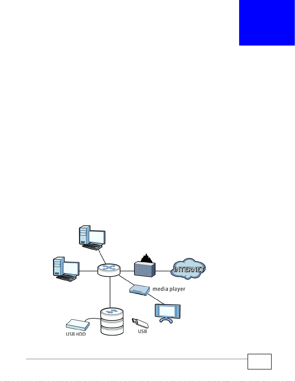
Figure 1 Example of the NAS in a Home Network
CHAPTER 1
Getting to Know Your NAS
NAS540 User’s Guide 15
Page 16

Chapter 1 Getting to Know Your NAS
Press
1 Beep
2 Beeps
2 more seconds
Release for
3 seconds
Release for
software
shutdown
hardware
shutdown
Above is the NAS in a home network. Users back up and share data on the NAS. The media player
plays the NAS’s media files on the TV. A USB hard drive provides extra storage space and files are
copied directly from the USB mass storage device to the NAS.
Place the NAS behind a firewall and/or IDP (Intrusion Detection and Prevention) device to protect it
from attacks from the Internet.
Refer to the Quick Start Guide for hardware connections and how to install and remove hard drives
from the disk trays.
Note: Turn off and disconnect the NAS before you install or remove the internal hard disk
or disks.
1.1.1 Hard Disks
The NAS has four internal hard disk bays. Install one to four SATA (Serial Advanced Technology
Attachment) hard disks. Note that the SATA hard disks are treated as internal or SATA volumes.
Any hard disk connected to a USB port is considered an external or USB volume.
1.1.2 SD Card
Use up to a 128 GB SDXC card with the front panel SD card slot. The SD card slot works with the
COPY/SYNC button (see Section 1.1.4 on page 16 for details).
1.1.3 Power Button
Use the power button on the front panel to turn the NAS on or off.
• Press the power button for one second to turn on the NAS.
Figure 2 Using the Power Button to Turn Off the NAS
• To have the NAS go through its normal software shutdown process and turn itself off, press the
power button until you hear one beep (after about three seconds), then release it.
• To perform a hardware shutdown and have the NAS immediately turn itself off without going
through the normal shutdown process, press the power button until you hear a second beep
(after about five seconds), then release it.
1.1.4 COPY/SYNC Button
Use the COPY/SYNC button on the front panel to copy or synchronize files between a connected
USB or SD device and the NAS. See Section 10.11 on page 219 for more details on how to
configure the copy/sync settings.
16
NAS540 User’s Guide
Page 17

1.1.5 RESET Button
Press
1 Beep
2 Beeps
IP Address
Password
Clear All Settings
5 more seconds
Release to
Release to Reset
Use the RESET button on the rear panel to restore the NAS’s default settings.
Figure 3 The RESET Button
• Press the RESET button until you hear one beep (after about two seconds), then release it. You
will hear one more beep after you release the button.
This resets the NAS’s IP address and password to the default values.
• Press the RESET button until you hear two beeps. After the second beep, continue pressing the
button for five more seconds, then release it. You will hear three quick beeps after you release
the button.
This resets the NAS to the factory default configuration. All settings you have configured on the
NAS, including IP address, password, user accounts, groups, and so on will be reset to the
factory defaults.
The reset process does NOT affect the volume settings, nor data stored on the NAS.
Chapter 1 Getting to Know Your NAS
You should periodically back up your configuration file to your computer (see Section 19.5 on page
305 for details about managing the NAS’s configuration file). You could then restore your
configuration in the event that you or someone else reset the NAS to the factory defaults.
Note: Keep the NAS in a secure location in order to prevent unauthorized reset of the
device.
You may need to close and re-open the NAS Starter Utility to discov er the NAS. This is because the
NAS automatically re-acquires IP address information, so its IP address may change. If no IP
address information is assigned, the NAS uses Auto-IP to assign itself an IP address and subnet
mask. For example, you could connect the NAS directly to your computer. If the computer is also
set to get an IP address automatically, the computer and the NAS will choose addresses for
themselves and be able to communicate.
NAS540 User’s Guide
17
Page 18

Chapter 1 Getting to Know Your NAS
18
NAS540 User’s Guide
Page 19

Note: Installing this version of the NAS Starter Utility uninstal ls p r evious versions.
2.1 Overview
Use the NAS Starter Utility to find and access the NAS and access the files on it.
The NAS Starter Utility supports Windows XP, Windows Vista, Windows 7, and Windows 8. Click
Help to open a Web Help page about the NAS Starter Utility screens. NAS Starter Utility screens are
shown here as they display with the Windows platform.
Note: Refer to the Quick Start Guide for your NAS’s hardware connections and the steps
for installing the NAS Starte r U til ity.
CHAPTER 2
NAS Starter Utility
2.2 Starting the NAS Starter Utility
• The NAS Starter Utility broadcasts a request packet when you first run it. Each NAS has an NAS
Starter Utility Agent that always listens and responds to requests from the NAS Starter Utility.
The NAS Starter Utility receives the response packet that contains information, such as host
name, IP, and so on.
• If you plan to use more than one NAS in your network, configure them with unique server
names. This enables you to identify each NAS in the NAS Starter Utility screens.
2.3 NAS Seeker Screen
Use this screen to view the NASs in your network. The NAS’s Server Name. The default is ‘NAS’
followed by the number of your model (‘NAS540’ for example). See Section 2.6 on page 23 for
how to change it to a more recognizable one in your network.
NAS540 User’s Guide 19
Page 20
Chapter 2 NAS Starter Utility
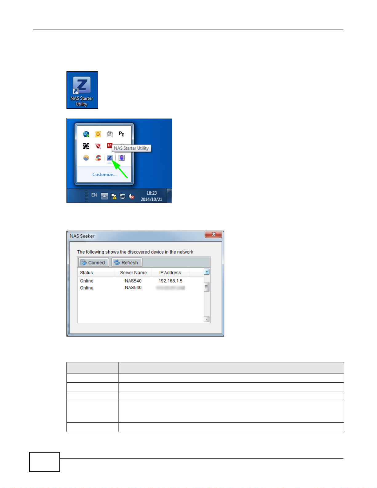
Click the NAS Starter Utility icon on your desktop or in the Windows system tray to start the NAS
Starter Utility. Alternatively you can click Start > Programs > ZyXEL > NAS Starter Utility.
Figure 4 NAS Starter Utility Desktop Icon
Figure 5 NAS Starter Utility Windows System Tray Icon
The first time you open the NAS Starter Utility the discovery screen appears as follows.
Figure 6 NAS Seeker
The following table describes the labels in this screen.
Table 1 NAS Seeker
LABEL DESCRIPTION
Connect Select a NAS and click this to connect to it.
Refresh Click this to refresh the screen. The NAS Starter Utility does not automatically refresh.
Status This shows whether the NAS is Online, Unreachable, Configuring, or Config Failed.
Server Name This is the server name you configured for the NAS. If you have more than one NAS in
your network, it is recommended that you give each one a unique name for identification
purposes.
IP Address This is the current IP address of the NAS.
20
NAS540 User’s Guide
Page 21
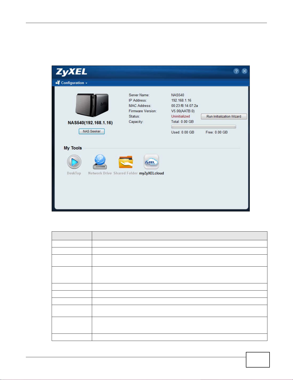
2.4 Main NAS Starter Utility Screen
The main NAS Starter Utility screen displays after you select an NAS in the NAS Seeker screen.
Figure 7 NAS Starter Utility Main Screen
Chapter 2 NAS Starter Utility
The following table describes the labels in this screen.
Table 2 NAS Starter Utility Main Screen
LABEL DESCRIPTION
? Click this to display the utility help.
Configuration Click this to configure system sett ings (see Section 2.6 on page 23).
NAS Seeker Click this to use the NAS Seeker screen (Section 2.3 on page 19) to find and connect to a
different NAS on your network.
Server Name This is the server name you configured for the NAS. If you have more than one NAS in
your network, it is recommended that you give each one a unique name for identification
purposes.
IP Address This is the current IP address of the NAS.
MAC Address This is the NAS’s unique physical hardware address (MAC).
Firmware Version This shows the version of firmware the NAS is currently using.
Status This shows whether the NAS is Online, Uninitialized, Unreachable, Configuring, or
Config Failed.
Run Initialization
Wizard
Capacity This shows the NAS’s total, in-use, and remaining storage capacity.
This button displays if the NAS detects that the NAS has not yet configured any of the
installed hard disks. Click this button to go to the Web Configurator login screen (see
Section 4.2 on page 29).
NAS540 User’s Guide
21
Page 22
Chapter 2 NAS Starter Utility
Table 2 NAS Starter Utility Main Screen
LABEL DESCRIPTION
DeskT op Click this button to go to the W eb Configurator lo gin screen (see Section 4.2 on page 29).
Network Drive Click this to add the NAS as a network drive in your computer’s Windows Explorer.
Shared Folder Click this to log into the NAS’s file directory in Windows Explorer.
myZyXELcloud Click this to go to myclou d.zyxel.c om to set up a free DDNS hostnam e for the NAS so y ou
can connect to it easily from the Internet.
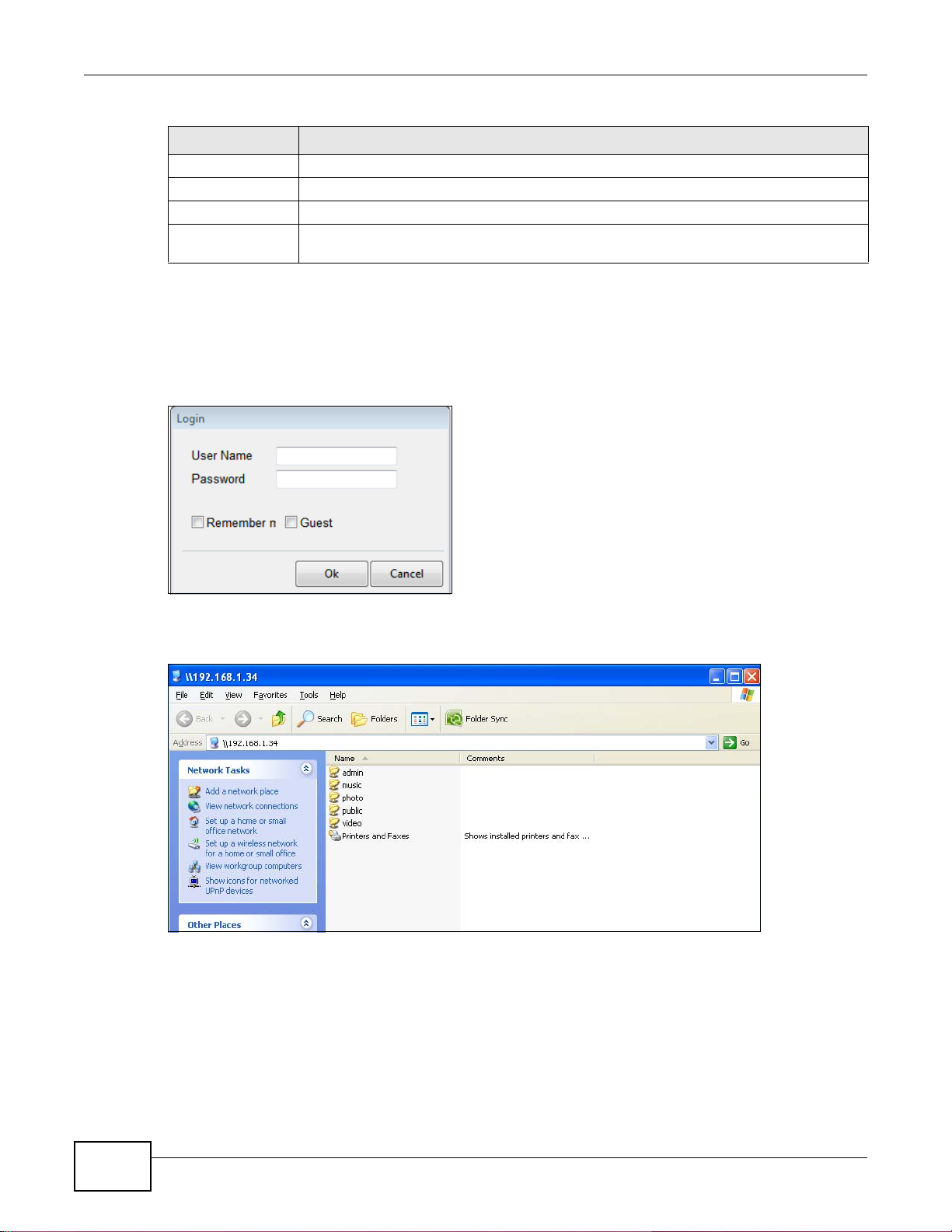
2.4.1 Directory of the NAS
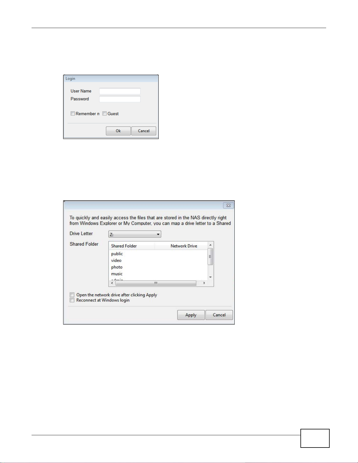
Click Shared Folder to log into the NAS’s file directory in Windows Explorer. Enter the
administrator user name and password and click Login.
Figure 8 Login
The utility opens the NAS’s directory in Windows Explorer.
Figure 9 Directory
2.5 Network Drive
In the main NAS Starter Utility screen click Network Drive to add the NAS as a network drive in
your computer’s Windows Explorer.
22
NAS540 User’s Guide
Page 23
Chapter 2 NAS Starter Utility
Enter your user name and password and click Login to be able to add the NAS’s shares to which
you have access as network drives. Otherwise select Guest and click Login to be able to add the
NAS’s public shares as network drives.
Figure 10 Login
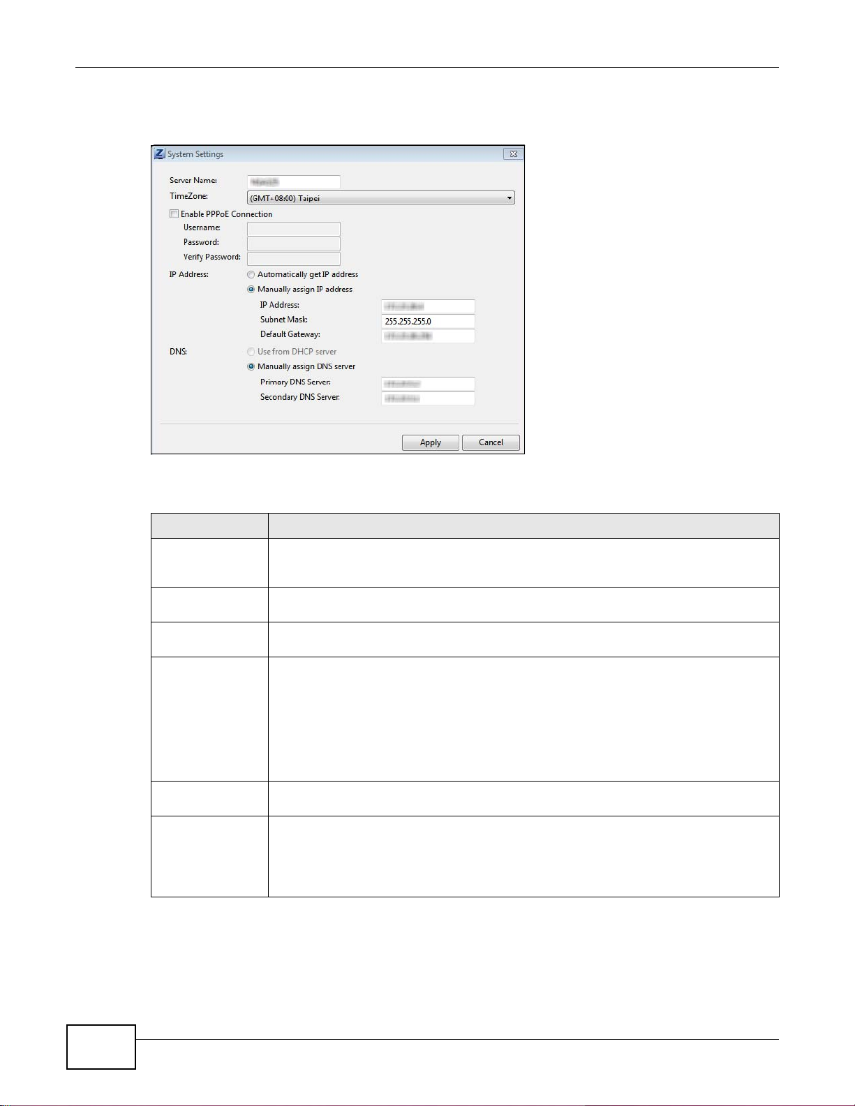
Select a share on the NAS and the drive letter on your computer to which you want to map it. The
shares that each user can select to map depends on the user’s permissions. For example, if share1
is private to user1, then only user1 is allowed to map share1. The table displays the NAS shares
that are already mapped to drive letters on your computer. After you click Apply you can see the
new drive in Windows Explorer (My Computer) where you can access and use it like your
computer’s other drives.
Figure 11 Network Drive
2.6 Configure System Settings
Use these screens to be able to change the NAS’s server name, time zone, PPPoE, IP address,
subnet mask, default gateway, or DNS settings.
NAS540 User’s Guide
23
Page 24
Chapter 2 NAS Starter Utility
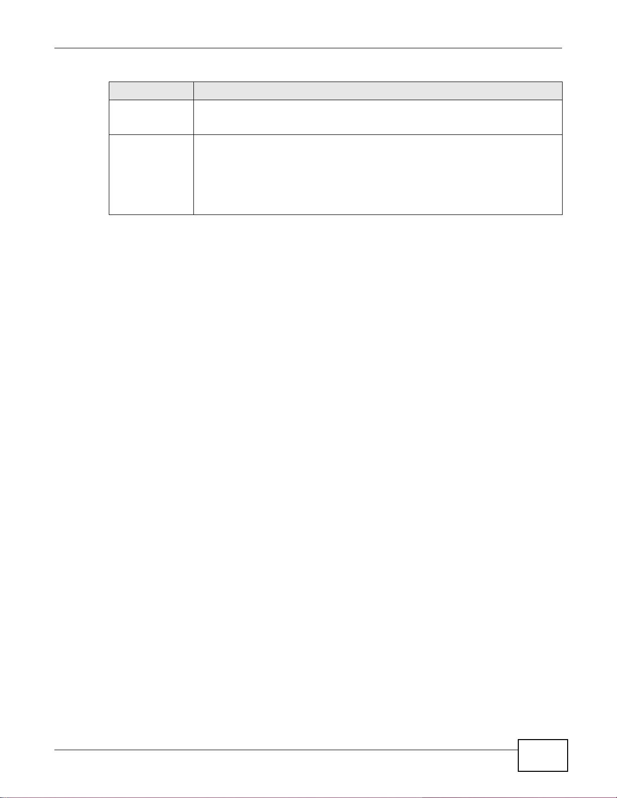
Click Configuration > System Setting in the main utility screen to display the following screen.
Figure 12 NAS Starter Utility > Configuration > System Setting
The following table describes the labels in this screen.
Table 3 NAS Starter Utility > Configuration > System Setting
LABEL DESCRIPTION
Server Name Specify a name to uniquely identify the NAS on your network. You can enter up to 15
alphanumeric characters with minus signs allowed but not as the last character. The
name must begin with an alphabetic character (a-z) and is case sensitive.
Time Zone Choose the time zone of your location. This will set the time difference between your
time zone and Greenwich Mean Time (GMT).
Enable PPPoE
Connection
IP Address Use these fields to configure the IP address of the LAN interface through which you are
Automatically get
IP address
Manually assign IP
address
Click this if your Internet connection requires you to enter a user name and password to
connect to the Internet. Enter your user name and password
connected to the NAS.
When the LAN interfaces are set to stand-alone, this configures the IP address of the LAN
interface in the same subnet as your computer . It configures LAN1 if both LAN interfaces
are in the same subnet as your computer.
If you use the administrator configuration screens to set the LAN interfaces to link
aggregation, this configures the IP address that both LAN interfaces share.
Select this if the NAS is automatically assigned an IP address from the ISP or a DHCP
server in your network.
Select this if you want to assign the NAS a fixed IP address, subnet mask and default
gateway.
Note: Do not configure an IP address that is already in use in your network. This results to
a network IP address conflict and makes the NAS inaccessible.
24
NAS540 User’s Guide
Page 25
Chapter 2 NAS Starter Utility
Table 3 NAS Starter Utility > Configuration > System Setting
LABEL DESCRIPTION
Use from DHCP
server
DNS Domain Name System (DNS) is for mapping a domain name to its corresponding IP
Domain Name System (DNS) is for mapping a domain name to its corresponding IP
address and vice versa. Select this if the NAS is automatically given DNS information
from the ISP or a DHCP server in your network.
address and vice versa.
Select Use from DHCP server if the NAS is automatically given DNS information from
the ISP or a DHCP server in your network.
Select Manually assign DNS server if you were given specific IP address(es) of the
DNS server(s). Enter the primary and secondary DNS in the corresponding fields.
NAS540 User’s Guide
25
Page 26

Chapter 2 NAS Starter Utility
26
NAS540 User’s Guide
Page 27
3.1 zCloud
Install the zCloud app from Google Play or the Apple App store on your Android or iOS device to
access the NAS’s media files from your mobile device and upload media files from your mobile
device to the NAS.
• Browse your media contents from your NAS directly on your Android or iOS device
• View photos stored on your NAS with the app's built-in slideshow
• Play music stored on your NAS
• Watch videos stored on your NAS
• Upload files from your Android device to your NAS
• Upload photos and videos from your iOS device to your NAS
• Browse and manage files stored on the NAS
• Compatibility: Requires Android 4.0.3 or later or iOS 7 or 8.
CHAPTER 3
zCloud
After installing the zCloud app on your device, tap the zCloud icon to open it.
Figure 13 zCloud Icon
NAS540 User’s Guide 27
Page 28
Chapter 3 zCloud
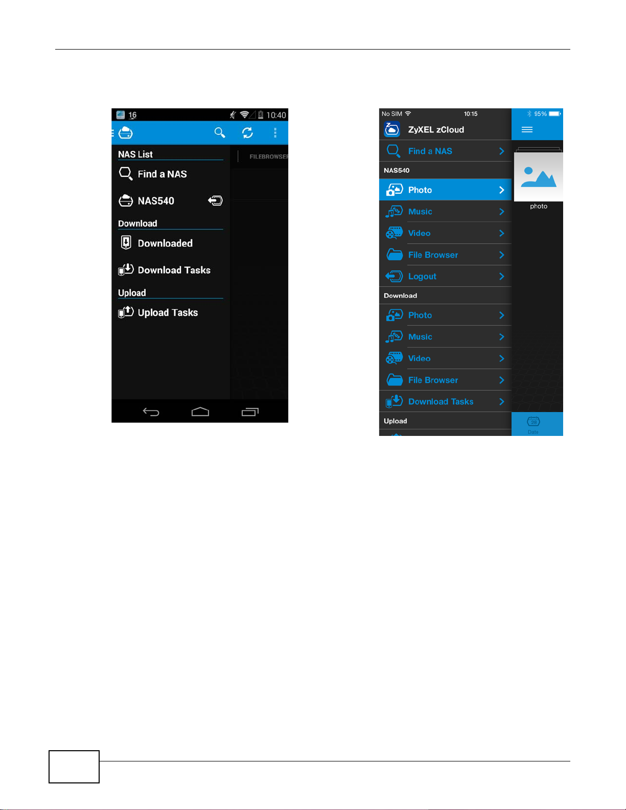
The main menu displays.
Figure 14 zCloud Android and iOS Main Menus
Find a NAS - use your NAS’s IP address and your user name and password to connect to it.
NAS540 - access the NAS’s default photo, music, and video shares. Y ou can play, download, upload
and manage files.
Download - access and manage files downloaded from the NAS to your Android or iOS device and
manage download tasks.
Upload - view and manage upload tasks.
28
NAS540 User’s Guide
Page 29
4.1 Overview
This chapter describes how to access the NAS web configurator and provides an overview of its
screens. The web configurator is an HTML -based management interface that allows easy NAS setup
and management using an Internet browser.
Use Internet Explorer 11.0.9, Mozilla Firefox 31.0, Safari 5.1.7, Google Chrome 37.0.2, or later
versions of these browsers. The recommended screen resolution is 1440 by 900 pixels or higher.
In order to use the web configurator you need to allow:
• Web browser pop-up windows from your device. Web pop-up blocking is enabled by default in
Windows XP SP (Service Pack) 2.
• JavaScript (enabled by default).
CHAPTER 4
Web Configurator Basics
4.2 Accessing the NAS Web Configurator
1 Make sure your NAS is properly connected and that your computer is in the same subnet as the
NAS (refer to the Quick Start Guide or the appendices).
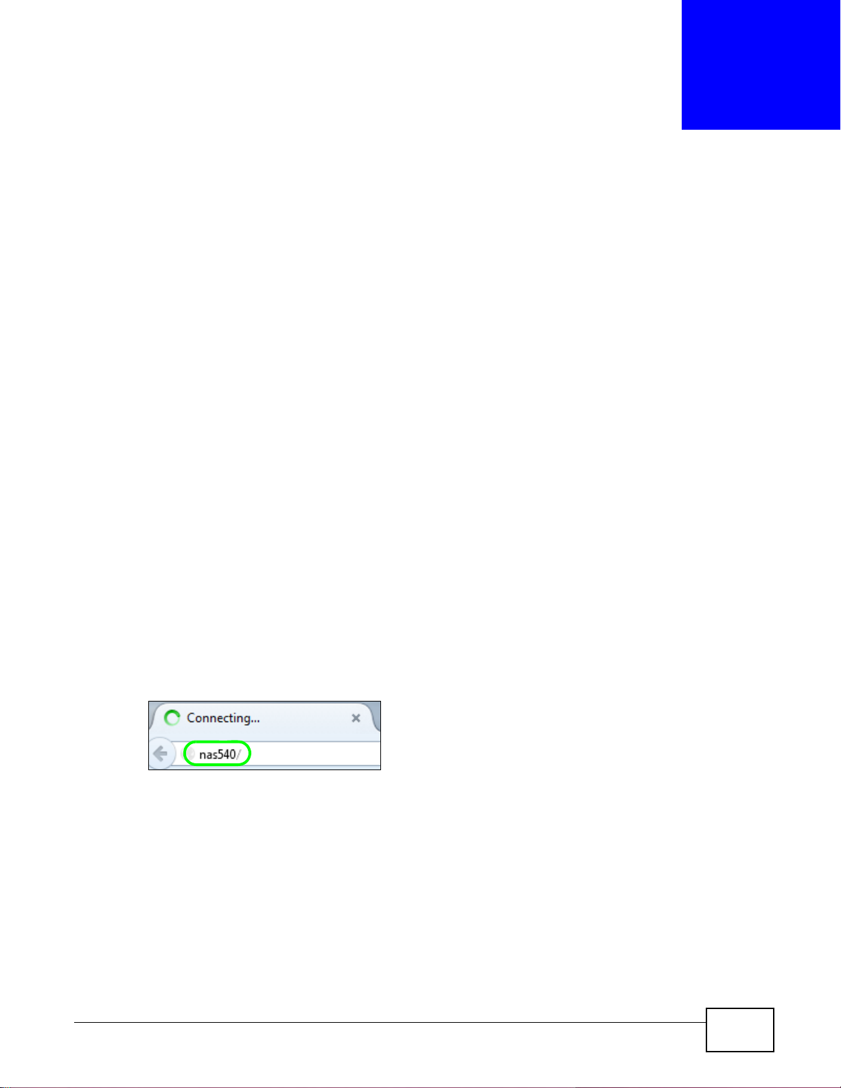
2 Open your browser and type in the server name of the NAS. The default is “nas” followed by the
number of your model (“nas540” for example). Configure the server name of your NAS using the
Network Configuration screen (Section 2.6 on page 23) of the NAS Starter Utility.
Figure 15 NAS URL
NAS540 User’s Guide 29
Page 30
Chapter 4 Web Configurator Basics
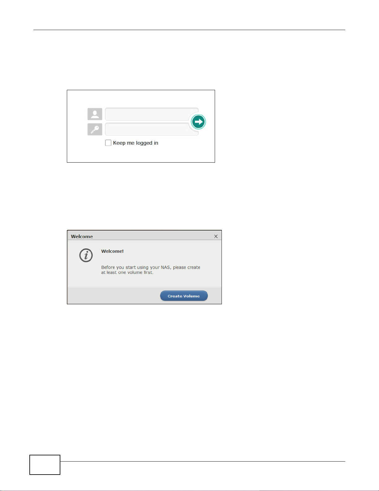
3 The default username and password are “admin” and “1234” respectively . Enter your username and
password. See Chapter 15 on page 273 for how to create other user accounts. If you use the option
to stay logged in (assuming you do not log out), make sure you keep your computer secure from
unauthorized access. Click the arrow to log in. Logging in with a (non-administrator) user account
takes you to the Playzone screens (see Section 4.5 on page 72 for details).
Figure 16 NAS Login Screen
Make sure you have a backup of any existing data in the hard disk before
installing it in the NAS. Creating a volume formats the hard disk and
deletes all data in the process.
4 This screen displays if you have not created a volume yet. Click Create Volume to make a volume
or click the x to close the screen to go to the Desktop (Section 4.3 on page 32).
Figure 17 Welcome Screen
30
NAS540 User’s Guide
Page 31

Chapter 4 Web Configurator Basics
5 Select Create single volume on RAID for a simple set up. Go to Section 4.4.1.1 on page 40 for
details.
Select Create Multiple volumes on disk group to be able to create more than one storage
volume. Go to Section 4.4.1.3 on page 50 for details.
Figure 18 Welcome Screen
NAS540 User’s Guide
31
Page 32

Chapter 4 Web Configurator Basics
23 4 5
14
6 7 8 9 10 11
12
1
13
4.3 Desktop
The Desktop screen displays after you log in.
Figure 19 Desktop
Note: The Web Configurator session automatically times out if left idle for 15 minutes.
Simply log back into the NAS if this happens to you.
1 Desktop - click this to minimize all windows so you can see the desktop. Click it again to restore
the windows to their previous state.
2 Storage - click this to open the storage configuration screens.
3 Administrator - click this to open the administrator configuration screens in a new tab.
4 Playzone - click this to open the Playzone screens in a new tab. Use the Playzone screens to view
and play media files in the shares that publish them.
5 User - click this to display the Logout link.
6 myZyXELcloud - click this to go to mycloud.zyxel.com to set up a free DDNS hostname for the
7 Storage - click this to open the storage configuration screens.
8 Administrator - click this to open the administrator configuration screens in a new tab.
NAS so you can connect to it easily from the Internet.
32
NAS540 User’s Guide
Page 33

9 Playzone - click this to use the Playzone media server screens to view and play media files in the
shares that publish them.
10 Status Center - click this to display NAS status information.
11 External Volume - click this to display the External Volume administrator configuration screen in
a new tab.
12 App Center - click this to display the Package Management administrator configuration screen in
a new tab.
13 Help - click this to display the NAS’s embedded help system screens.
14 Status - click the Status icon at the bottom of the Desktop screen to hide or display device status
information. When you display status information, click the Status Center icon to display
additional NAS status information.
4.3.1 Status Center
In the Desktop screen, click Status Center to display this screen of NAS status information.
Chapter 4 Web Configurator Basics
Figure 20 Status Center
The following table describes the labels in this screen.
Table 4 Status Center
LABEL DESCRIPTION
Refresh Click the Refresh icon to update this display.
Status The circular icon displays the health state of the NAS. A green circle with a check
Server Name This displays the name which helps you find the NAS on the network.
NAS540 User’s Guide
mark indicates healthy.
33
Page 34

Chapter 4 Web Configurator Basics
Table 4 Status Center (continued)
LABEL DESCRIPTION
Model Name This displays which model this NAS device is.
Firmware Version This is the NAS firmware version.
LAN1 MAC Address This displays the NAS’s unique physical hardware address (MAC) for the LAN1
LAN2 MAC Address This displays the NAS’s unique physical hardware address (MAC) for the LAN2
CPU This displays a summary of CPU usage by all current processes.
Memory This shows how much of the NAS's total memory is being used.
CPU Temperature This displays the temperature near the N AS’s CPU. The NAS generates an
Fan Speed This is the RPM (Rotations Per Minute) of the NAS’s fans.
Ethernet port. You need the MAC address to register the product at myZyXEL.com.
Customer support may also request it for troubleshooting purposes.
Ethernet port.
Note: If too many users are using the NAS then the NAS may appear sluggish.
emergency log if the temperature goes out of the normal operating range. If the
temperature goes even higher, the NAS shuts down automatically to avoid
damage from overheating. If the NAS overheats, make sure the fans are working
and it is in a well ventilated place.
4.4 Storage
From the Desktop screen, click Storage to display the Storage screens. Use the Storage screens
to configure disk groups and volumes. The Storage Overview screen displays the current storage
configuration and volume usage.
Figure 21 Storage Overview
34
NAS540 User’s Guide
Page 35

Chapter 4 Web Configurator Basics
The following table describes the labels in this screen.
Table 5 Storage Overview
LABEL DESCRIPTION
Storage The circular icon displays the overall health state of the NAS.
A green circle with a check mark indicates healthy.
An orange circle with an exclamation mark indicates attention. This appears when
a volume or disk group is degraded. Click Repair to repair it.
An red circle with an exclamation mark indicates danger. This appears when a
volume or disk group is crashed. You cannot recover the volume.
Volume Usage This shows how much of each volume is currently used.
Volume This section shows the current storage usage for each volume built directly on top
of a RAID. These volumes have higher access performance than volumes on a disk
group but are less flexible in regards to size.
Details include the currently used percentage of the volume.
Used (Normal) - green on the circle represents the volume’s perc entage of used
capacity in a healthy state.
Used (Degraded) - orange on the circle represents the volume’s percentage of
used capacity in a degraded state. Degraded means one or more disks has failed
but you can still replace a faulty disk to recover the volume.
Crashed - a red exclamation point represents the volume is in a down state.
Down means you cannot recover the volume.
Available - gray on the circle represents the volume’s percentage of unused
capacity.
This section also displays the volume’s used capacity, and total capacity available.
Volume on Disk Group This section shows the current storage usage for each volume built on top of a
disk group. You can expand a volume’s size after creation if the disk group has
unallocated space. You can also expand a disk group by adding hard disks.
4.4.1 Storage Volume
A volume is a basic storage space on the NAS. To store data on the NAS, you must create at least
one volume. Your NAS supports the following:
• Internal volumes (built on the hard disks installed in the NAS)
• External volumes (built on the external storage devices attached to the NAS)
Internal Volumes
Table 6 Internal Volumes
OPTION DESCRIPTION
Volume Allocates all the available space to the volume.
Volume on Disk
Group
NAS540 User’s Guide
Provides better performance.
Allows you to create multiple volumes on a disk group.
Allows you to customize the size of a volume.
35
Page 36

Chapter 4 Web Configurator Basics
RAID Types
Table 7 RAID Types
RAID
TYPE
Basic 1 0 Use Basic with one disk. It has no fault
JBOD 2-4 0 Use JBOD with two or more disks for
RAID 0 2-4 0 Use RAID 0 with two or four disks for
RAID 1 2-4 (No. of HDD) -1 Use RAID 1 to create an exact copy of data
RAID 5 3-4 1 Use RAID 5 with three or four disks to
NO. OF
HDD
NO. OF HDD
ALLOWED TO
FAIL
DESCRIPTION CAPACITY
tolerance.
maximum capacity. This is just a collection of
disks with no fault tolerance.
maximum speed and no fault tolerance.
on one disk to a second disk. Use this with
two to four disks to mirror primary data to
another disk(s) with high performance.
You can add a hot spare to a 2-disk RAID 1.
balance performance and hard disk capacity
usage with data protection in case of disk
failure.
1 x (HDD size)
sum of HDD sizes
sum of HDD sizes
Smallest HDD size
(No. of HDD – 1) x
(smallest HDD
size)
You can add a hot spare to a 3-disk RAID 5.
RAID 6 4 2 Use RAID 6 with four disks for more data
protection in case of disk failure.
RAID 10 4 1 HDD in each
RAID 1 group
Use RAID 10 with four disks to get better
performance than RAID 6, with slightly less
data protection.
(No. of HDD – 2) x
(smallest HDD
size)
(No. of HDD / 2) x
(smallest HDD
size)
Repair Volumes or Disk Groups
If a hard disk in a RAID 1 with a hot spare or a RAID 5 with a hot spare fails, the NAS automatically
uses the hot spare to re-build the volume or disk group. Later you can replace the failed hard disk
and add the new disk as a hot spare.
A hard disk failure in a RAID 1, RAID 5, RAID 6, or RAID 10 degrades the volume or disk group.
Replace the failed disk and use the Storage screen’s Repair link to repair the volume.
Change RAID Type
You can change the f ollowing RAID types without losing stored data. This can help you manage you r
storage capacity as you add more disks.
Table 8 Internal Volumes
RAID TYPE WHAT YOU CAN CHANGE IT TO
Basic RAID 1
RAID 1 RAID 1 with a hot spare or RAID 5
RAID 5 RAID 5 with a hot spare or RAID 6
36
NAS540 User’s Guide
Page 37

Chapter 4 Web Configurator Basics
Expand Volumes or Disk Groups
As your content grows, you can do the following to expand the storage capacity of a volume or disk
group without losing stored data.
Table 9 Expand Volumes and Disk Groups
EXPANSION
METHOD
Using
unallocated disk
space
Adding disks You can add one or more disks to a JBOD, RAID 1 or RAID 5.
Replacing with
larger disks
DESCRIPTION
You can add more storage space to a volume if there is still some space unalloc ated on the
same disk group.
The hard disk you want to add must have capacity equal to or greater than the smallest
disk in the volume or disk group.
You can replace smaller disks in a RAID 1, RAID 5, or RAID 6 with larger disks.
Replace disks one-by-one.
Replace the smallest disk in the volume or disk group first.
After replacing a disk, you must use the Storage screen’s Manage link to repair the
volume.
What for the repair process to complete before you replace another disk.
Use the Volume screen to configure and manage internal volumes. From the Storage screen, click
Volume to open the screen as shown.
Note: Configure and manage external volumes through the administrator mode. See
Section 4.6 on page 84 for more information.
Figure 22 Storage Volume
NAS540 User’s Guide
37
Page 38

Chapter 4 Web Configurator Basics
The following table describes the labels in this screen.
Table 10 Storage Volume
LABEL DESCRIPTION
Volume
Use this section to configure and manage volumes built on hard disks directly.
Create Click this to format internal hard disks and create a n ew volume. All data on the disk(s)
will be lost.
Note: This button is not available while the NAS is creating, deleting, or changing the
RAID type of any volume or disk group.
A pop-up screen appears if all installed hard disks are used by other volumes
or disk groups. You will need to install another hard disk into the NAS if any disk
tray is available or remove unnecessary volumes or disk groups to release the
storage space. Click OK to close this screen.
Figure 23 No Disk in NAS
Manage Select a volume and click Manage to edit, repair or expand the volume.
Note: This button is available only when you can repair, expand or change RAID type.
Delete Select a volume and click Delete to remove it.
Note: If you delete a volume, all data in the volume disks is erased.
Add Hot Spare Select a RAID 1 or RAID 5 volume and click Add Hot Spare to add another disk as a
hot-spare (standby) to the RAID array. A pop-up screen displays.
Figure 24 Add Hot Spare
Select a disk from the drop-down list box and then click Apply.
See Section 4.4.7 on page 67 for more information about RAID.
Note: The capacity of the disk you are adding must be equal to or greater than the largest
disk in the RAID 1 or RAID 5 array.
38
NAS540 User’s Guide
Page 39

Chapter 4 Web Configurator Basics
Table 10 Storage Volume (continued)
LABEL DESCRIPTION
Remove Hot Spare Select a RAID 1 or RAID 5 volume and click Remove Hot Spare to remove the standby
drive from the RAID array.
Status This field shows whether the volume is normal, degraded, crashed, Creating, Deleting,
Expanding, Repairing or Changing the RAID type.
Normal: A green circle represents a healthy volume.
Degraded: An orange circle represents a degraded RAID 1 volume.
Crashed: A red circle represents a down volume.
The following status also displays the percentage of an action has been completed.
Creating: The NAS’s percentage progress in creating the volume.
Deleting: The NAS’s percentage progress in deleting the volume.
Expanding: The NAS’s percentage progress in expanding the volume. For a RAID 1
volume, this also displays the percentage of resynchronizing the NAS has finished and
the evaluated remaining time.
Repairing: The NAS’s percentage progress in repairing the volume. For a RAID 1
volume, this also displays the percentage of resynchronizing the NAS has finished and
the evaluated remaining time.
Changing: The NAS’s percentage progress in changing the volume’s RAID type. For a
RAID 1 volume, this also displays the percentage of resynchronizing the NAS has
finished and the evaluated remaining time.
Volume Name This field shows the name of the volume. Click the column’s heading cell to display an
arrow. Use the arrow to sort the table entries in ascending or descending order.
RAID Type This field shows what type of disk storage technology (Basic, a RAID level or JBOD) a
Available Capacity This field shows the percentage of the volume being used, the percentage that is
Hot Spare This field shows the name of the standby disk if there is any for a RAID 1 or RAID 5
Volume on Disk Group
Use this section to configure and manage volumes built on disk groups.
Create Click this to format internal hard disks and create a new volume on a disk group. All data
volume uses.
available, and the total disk size.
volume. Otherwise, it shows not supported.
on the disks will be lost.
Note: This button is unavailable when a volume or disk group is being created, deleted or
changing the RAID type.
Edit Select a volume and click Edit to expand the volume’s capacity.
Delete Select a volume and click Delete to remove it.
Note: If you delete a volume, all data in the volume disks is erased.
Note: Deleting a volume on a disk group here does not delete the corresponding disk
group. To delete a disk group, click Storage > Disk Group.
Disk Group X This field shows the name of the disk group, the percentage of the disk group size that is
available, the disk group size being used, and the total disk group size.
NAS540 User’s Guide
39
Page 40

Chapter 4 Web Configurator Basics
Table 10 Storage Volume (continued)
LABEL DESCRIPTION
Status This field shows whether the volume is normal, degraded, crashed, Creating, Deleting,
Volume Name This field shows the name of the volume. Click the column’s heading cell to display an
File System This field shows what file system the volume uses. At the time of writing, your NAS uses
Available Capacity This field shows the percentage of the volume being used, the percentage that is
Expanding, Repairing or Changing the RAID type.
Normal: A green circle represents a healthy volume.
Degraded: An orange circle represents a degraded RAID 1 volume.
Crashed: A red circle represents a down volume.
The following status also displays the percentage of an action has been completed.
Creating: The NAS’s percentage progress in creating the volume.
Deleting: The NAS’s percentage progress in deleting the volume.
Expanding: The NAS’s percentage progress in expanding the volume. For a RAID 1
volume, this also displays the percentage of resynchronizing the NAS has finished and
the evaluated remaining time.
Repairing: The NAS’s percentage progress in repairing the volume. For a RAID 1
volume, this also displays the percentage of resynchronizing the NAS has finished and
the evaluated remaining time.
Changing: The NAS’s percentage progress in changing the volume’s RAID type. For a
RAID 1 volume, this also displays the percentage of resynchronizing the NAS has
finished and the evaluated remaining time.
arrow. Use the arrow to sort the table entries in ascending or descending order.
the EXT4 file system for internal volumes.
available, and the total disk group size.
4.4.1.1 Creating a Volume
Use the Create Volume screen to configure a volume directly on a disk/RAID, which has better
performance Click Create in the Volume section of the Storage > Volume screen to open the
screen as shown.
40
NAS540 User’s Guide
Page 41

Chapter 4 Web Configurator Basics
Note: Create a volume on a disk group instead if you want to ha ve multip le volumes on a
disk. See Section 4.4.1.3 on page 50 for more information.
Figure 25 Create Volume
The following table describes the labels in this screen.
Table 11 Create Volume
LABEL DESCRIPTION
Step 1. Select Disks and RAID Type
Select disks This section lists all a v ailabl e hard disks in the table and displays the disk tr ays where they
Disk Name This field shows the name of the hard disk.
Size This field shows the total disk size.
Model Name This field shows the model of the hard disk.
NAS540 User’s Guide
are currently installed on the graphic at the right.
Select one or more hard disks where you want to create a volume. Use the check box on
the top to select or unselect all entries in this column.
41
Page 42

Chapter 4 Web Configurator Basics
Table 11 Create Volume (continued)
LABEL DESCRIPTION
Choose a RAID
type
Select a RAID type from the drop-down list box. The corresponding space allocations of
available size, data protection area, and wasted size display.
Use Basic with one disk.
Use JBOD with two or more disks for maximum capacity.
Use RAID 0 with two or four disks for maximum speed.
Use RAID 1 with two or more disks to mirror primary data to another disk(s) with high
performance.
Use RAID 5 with three or more disks to balance performance, hard disk capacity usage
with data protection in case of disk failure.
Use RAID 6 with four disks for more data protection in case of disk failure.
Use RAID 10 with four disks to get better performance than RAID 6, with slightly less data
protection.
See Table 7 on page 36 or Section 4.4.7 on page 67 for more information.
Note: Use the same capacity of hard disks for RAID 1, 5, 6, or 10 to avoid wasting space.
Back This button is not available at this step.
Next Click Next to go to the next step.
Cancel Click Cancel to close the screen without saving any settings.
Step 2. Summary
Use this screen to review the settings you configured in the last step.
Disk Selected This field displays the hard disks you have selected.
RAID Type This field displays the type of RAID on which the volume will be built.
Volume Type This field displays the type of the volume, Single volume on RAID (no disk group).
Volume Name This field displays the name of the volume.
Volume
Capacity
Back Click Back to go to the previous step.
Apply Click Apply to save the settings.
Cancel Click Cancel to close the screen without saving any settings.
This field displays the size of the volume.
4.4.1.2 Managing a Volume
Use the Manage Volume screen to repair, expand a volume or change the volume’s RAID type. In
the Storage > Volume screen, select a volume and then click Manage in the Volume section to
open the screen as shown.
42
NAS540 User’s Guide
Page 43

Chapter 4 Web Configurator Basics
A
The available options vary depending on the conditions it matches. For example, the Repair RAID
option is available only when a degraded volume is selected.
Figure 26 Manage Volume (Repair RAID)
NAS540 User’s Guide
43
Page 44

Chapter 4 Web Configurator Basics
A
Figure 27 Manage Volume (Expand the volume by adding disk(s) )
44
NAS540 User’s Guide
Page 45

Figure 28 Manage Volume (Change RAID Type)
Chapter 4 Web Configurator Basics
NAS540 User’s Guide
45
Page 46

Chapter 4 Web Configurator Basics
A
Figure 29 Manage Volume (Change RAID Type)
46
NAS540 User’s Guide
Page 47

Chapter 4 Web Configurator Basics
The following table describes the labels in this screen.
Table 12 Manage Volume
LABEL DESCRIPTION
Repair RAID Select this to repair a degraded RAID volume.
Expand the
volume by
adding disk(s)
Select this to add one or more disks to a JBOD, RAID 1 or RAID 5 volume. You can add a
disk to increase an array’s capacity or to use as a hot-spare (standby). When you add a
disk to an existing array, you do not have to re-create shares, access rights and so on as
you would if you create a new volume.
Note: This option is available when a disk has not been allocated to any volume or disk group
yet.
Expand the
volume with
unallocated disk
space
Change RAID
Type
The following describes labels on the following screens after you select Repair RAID in this screen.
Step 1. Select Disks
A This shows the name of the volume you have selected.
Status This field displays the status of the volume.
RAID Type This field displays the type of RAID on which the volume is buil t.
Disk Info
Status This field displays the status of the disk.
Disk Name This field displays the name of the disk.
Size This field displays the total capacity of the disk.
Model Name This field displays the model of the disk.
Select a disk to
replace the
failed one
Disk Name This field shows the name of a hard disk.
Size This field shows the total disk size.
Model Name This field shows the model of the hard disk.
Expected
Capacity
Select this to add more storage space to a volume if there is still some space unallocated on
the same disk group. Select this if the NAS fails to expand a volume by adding disk(s) and
the final volume capacity is not as expected. For example, you want to expand a 1 TB RAID
1 volume by adding two more 1 TB disks. The volume size sh ou ld be 2 TB afte r e xpans ion,
however, you just see 1 TB. Use this option to fix the issue.
Select this if you want to change the volume’s RAID type from Basic to RAID 1, RAID 1 to
RAID 5, or RAID 5 to RAID 6.
This section lists all available hard disks in the table and displays the corresponding disk
tray of the disks you selected on the graphic at the right.
Select one or more hard disks for increasing the volume’s capacity. Use the check box on
the top to select or unselect all entries in this column.
This field shows the corresponding space allocati ons of available size, data protection area,
and wasted size according to your selections on hard disks above.
Back Click Back to go to the previous step.
Next Click Next to go to the next step.
Cancel Click Cancel to close the screen without saving any settings.
Step 2. Summary
Use this screen to review the settings you configured in the last step.
Action This field displays for what the configuration is.
Volume Name This field displays the name of the volume.
Disk Selected This field displays the hard disks you have selected.
NAS540 User’s Guide
Note: Use the same capacity of hard disks for RAID 1, 5, 6, or 10 to avoid wasting space.
47
Page 48

Chapter 4 Web Configurator Basics
Table 12 Manage Volume (continued)
LABEL DESCRIPTION
Volume
Capacity
Back Click Back to go to the previous step.
Apply Click Apply to save the settings.
Cancel Click Cancel to close the screen without saving any settings.
The following describes labels on the following screens after you select Expand the volume by adding
disk(s) in this screen.
Step 1. Select Disks
A This shows the name of the volume you have selected.
Status This field displays the status of the volume.
RAID Type This field displays the type of RAID on which the volume is buil t.
Disk Info
Status This field displays the status of the disk.
Disk Name This field displays the name of the disk.
Size This field displays the total capacity of the disk.
Model Name This field displays the model of the disk.
Select disk(s) to
add
Disk Name This field shows the name of a hard disk.
Size This field shows the total disk size.
Model Name This field shows the model of the hard disk.
Expected
Capacity
This field displays the total available size of the volume.
This section lists all available hard disks in the table and displays the corresponding disk
tray of the disks you selected on the graphic at the right.
Select one or more hard disks for increasing the volume’s capacity. Use the check box on
the top to select or unselect all entries in this column.
This field shows the corresponding space allocati ons of available size, data protection area,
and wasted size according to your selections on hard disks above.
48
Note: Use the same capacity of hard disks for RAID 1, 5, 6, or 10 to avoid wasting space.
Back Click Back to go to the previous step.
Next Click Next to go to the next step.
Cancel Click Cancel to close the screen without saving any settings.
Step 2. Summary
Use this screen to review the settings you configured in the last step.
Action This field displays for what the configuration is.
Volume Name This field displays the name of the volume.
Disk Selected This field displays the hard disks you have selected.
Volume
Capacity
Back Click Back to go to the previous step.
Apply Click Apply to save the settings.
Cancel Click Cancel to close the screen without saving any settings.
The following describes labels on the following screens after you select Expand the volume with
unallocated disk space in this screen.
Summary
Action This field displays for what the configuration is.
This field displays the total available size of the volume.
NAS540 User’s Guide
Page 49

Chapter 4 Web Configurator Basics
Table 12 Manage Volume (continued)
LABEL DESCRIPTION
Volume Name This field displays the name of the volume.
Volume
Capacity
Back Click Back to go to the previous step.
Apply Click Apply to save the settings.
Cancel Click Cancel to close the screen without saving any settings.
The following describes labels on the following screens after you select Change RAID Type in this screen.
Step 1. Select Disks and RAID Type
A This shows the name of the volume you have selected.
Status This field displays the status of the volume.
RAID Type This field displays the type of RAID on which the volume is buil t.
Disk Info
Status This field displays the status of the disk.
Disk Name This field displays the name of the disk.
Size This field displays the total capacity of the disk.
Model Name This field displays the model of the disk.
Select disk(s) This section lists all available hard disks in the table and displays the corresponding disk
Disk Name This field shows the name of a hard disk.
Size This field shows the total disk size.
Model Name This field shows the model of the hard disk.
Choose a RAID
type
This field displays the total available size of the volume.
tray of the disks you selected on the graphic at the right.
Select one or more hard disks for changing the volume’s RAID type. Use the check box on
the top to select or unselect all entries in this column.
Select a RAID type from the drop-down list box. The corresponding space allocations of
available size, data protection area, and wasted size display.
Back Click Back to go to the previous step.
Next Click Next to go to the next step.
Cancel Click Cancel to close the screen without saving any settings.
Step 2. Summary
Use this screen to review the settings you configured in the last step.
Action This field displays for what the configuration is.
Volume Name This field displays the name of the volume.
Disk Selected This field displays the hard disks you have selected.
RAID Type This field displays the type of RAID on which the volume will be built.
NAS540 User’s Guide
Use RAID 1 with two or four disks to mirror primary data to another disk(s) with high
performance.
Use RAID 5 with three or more disks to balance performance, hard disk capacity usage
with data protection in case of disk failure.
Use RAID 6 with four disks for more data protection in case of disk failure.
See Table 7 on page 36 or Section 4.4.7 on page 67 for more information.
Note: Use the same capacity of hard disks for RAID to avoid wasting space.
49
Page 50

Chapter 4 Web Configurator Basics
Table 12 Manage Volume (continued)
LABEL DESCRIPTION
Volume
Capacity
Back Click Back to go to the previous step.
Apply Click Apply to save the settings.
Cancel Click Cancel to close the screen without saving any settings.
This field displays the total size of the volume.
4.4.1.3 Creating a Volume on Disk Group
Use the Create Volume on Disk Group screen to configure a volume on an existing or new disk
group. Click Create in the Volume on Disk Group section of the Storage > Volume screen to
open the screen as shown.
50
NAS540 User’s Guide
Page 51

Chapter 4 Web Configurator Basics
Note: It is suggested to create a volume directly on a disk instead of on a disk group if
high performance is important to you. See Section 4.4.1.1 on page 40 for more
information.
Figure 30 Create Volume on an Existing Disk Group
NAS540 User’s Guide
51
Page 52

Chapter 4 Web Configurator Basics
Figure 31 Create Volume on a New Disk Group
52
NAS540 User’s Guide
Page 53

Chapter 4 Web Configurator Basics
The following table describes the labels in this screen.
Table 13 Create Volume on Disk Group
LABEL DESCRIPTION
Choose an Action
Create Volume on Select Existing on disk group and a disk group from the drop-down list box to
The following fields describe the labels on the following screens if you select Existing on disk group on the
Choose an Action screen.
Step 1. Create Volume
Disk group information
Name This field displays the name of the disk group.
Unallocated capacity This field displays the percentage of the available size, the size in use, and total
Create Volume
Volume Name This field displays the default name of the volume. You can also type a new name
Allocated Volume Size This field displays the number of Gigabytes available on the volume by default.
Back Click Back to go to the previous step.
Next Click Next to go to the next step.
Cancel Click Cancel to close the screen without saving any settings.
Step 2. Summery
Volume Type This field displays the type of the volume, Multiple volumes on RAID (Disk
Volume Name This field displays the name of the volume.
Volume Capacity Th is field displays the size of the volume.
Back Click Back to go to the previous screen.
Next Click Next to go to the next step.
Cancel Click Cancel to close the screen without saving any settings.
The following fields describe the labels on the following screens after you select New disk group on the
Choose an Action screen.
Step 1. Select Disks and RAID Type
Select disks This section lists all available hard disks in the table and displays the disk trays
Disk Name This field shows the name of the hard disk.
Size This field shows the total disk size.
Model Name This field shows the model of the hard disk.
create a volume on the disk group. This option is available only when there is an
existing disk group available.
Select New disk group to create a disk group and then a volume on the disk
group.
size of the disk group.
for the volume.
You can change the size to allocate to this volume. Click MAX to allocate all
available size of the disk group to the volume.
Group X) where Disk Group X is the disk group’s name.
they are currently installed on the graphic at the right.
Select one or more hard disks where you want to create a volume. Use the check
box on the top to select or unselect all entries in this column.
NAS540 User’s Guide
53
Page 54

Chapter 4 Web Configurator Basics
Table 13 Create Volume on Disk Group (continued)
LABEL DESCRIPTION
Choose a RAID type Select a RAID type from the drop-down list box. The corresponding space
Back Click Back to go to the previous screen.
Next Click Next to go to the next step.
Cancel Click Cancel to close the screen without saving any settings.
Step 2. Create Volume
Disk group information
Name This field displays the name of the disk group.
Unallocated capacity This field displays the percentage of the available size, the size in used, and total
Create Volume
Volume Name This field displays the default name of the volume. You can also type a new name
Volume Capacity This field displays the number of Gigabytes available on the volume by default.
Back Click Back to go to the previous step.
Next Click Next to go to the next step.
Cancel Click Cancel to close the screen without saving any settings.
Step 3. Summary
Use this screen to review the settings you configured in the last step.
Disk Selected This field displays the hard disk(s) on which the RAID array will be built.
RAID Type This field displays the type of RAID on which the volume will be built.
Volume Type This field displays the type of the volume, Multiple volumes on RAID (Disk
Volume Name This field displays the name of the volume.
Volume Capacity Th is field displays the size of the volume.
Back Click Back to go to the previous step.
Apply Click Apply to save the settings.
Cancel Click Cancel to close the screen without saving any settings.
allocations of available size, data protection area, and wasted size display.
Use Basic with one disk.
Use JBOD with two or more disks for maximum capacity.
Use RAID 0 with two or four disks for maximum speed.
Use RAID 1 with two or more disks to mirror primary data to another disk(s) with
high performance.
Use RAID 5 with three or more disks to balance performance, hard disk capacity
usage with data protection in case of disk failure.
Use RAID 6 with four disks for more data protection in case of disk failure.
Use RAID 10 with four disks to get better performance than RAID 6, with slightly
less data protection.
See Table 7 on page 36 or Section 4.4.7 on page 67 for more information.
Note: Use the same capacity of hard disks for RAID 1, 5, 6, or 10 to avoid wasting
space.
size of the disk group.
for the volume.
You can set the si ze to allocate for this volume. Clic k MAX to allocate all av ail able
capacity of the disk group to the volume.
Group X) where Disk Group X is the disk group’s name.
54
NAS540 User’s Guide
Page 55

4.4.1.4 Editing a Volume on Disk Group
Use the Edit Volume on Disk Group screen to expand a volume’s capacity. In the Storage >
Volume screen, select a volume and then click Edit in the Volume on Disk Group section to open
the screen as shown.
Figure 32 Edit Volume on Disk Group
Chapter 4 Web Configurator Basics
The following table describes the labels in this screen.
Table 14 Edit Volume on Disk Group
LABEL DESCRIPTION
Unallocated
capacity on Disk
Group X
Current volume
size
New volume
size
Apply Click Apply to save the settings.
Cancel Click Cancel to close the screen without saving any settings.
This field displays the the percentage of the disk group size unallocated to other volumes,
the size in use, and total size of the disk group.
This field displays the total size of the volume, excluding the file system size.
This field displays the smallest size to which you can expand the volume (this includes the
volume’s current available size, file system size, and a minimum additional capacity for
expansion). You can enter a bigger number or click MAX to allocate all the rest of the space
in the disk group to the volume.
NAS540 User’s Guide
55
Page 56

Chapter 4 Web Configurator Basics
4.4.2 Disk Group
Use the Disk Group screen to configure and manage disk groups. From the Storage screen, click
Disk Group to open the screen as shown.
Figure 33 Disk Group
The following table describes the labels in this screen.
Table 15 Disk Group
LABEL DESCRIPTION
Create Click this to format internal hard disks and create a new disk group. All data on the disk(s)
will be lost.
Note: This button is not available while the NAS is creating, deleting, or changing the RAID
type of any volume or disk group.
Manage Select a volume and click Manage to edit, repair, or expand the volume.
Note: This button is available only when you can repair, expand or change RAID type.
Delete Select a disk group and click Delete to remove it.
Note: If you delete a disk group, all data in the disk group is erased.
Add Hot Spare Select a RAID 1 or RAID 5 disk group and click Add Hot Spare to add another disk as a
hot-spare (standby) to the RA ID array. See Section 4.4.7 on page 67 for more information.
Note: The capacity of the disk you are adding must be equal to or greater than the largest
disk in the RAID 1 or RAID 5 array.
Note: You need four hard disks installed to use RAID 5 with hotspare.
Remove Hot
Spare
Select a RAID 1 or RAID 5 disk group and click Remove Hot Spare to remove the standby
drive from the RAID array.
56
NAS540 User’s Guide
Page 57

Chapter 4 Web Configurator Basics
Table 15 Disk Group (continued)
LABEL DESCRIPTION
Disk Group X This field shows the name of the disk group and whether it is normal, degraded, crashed,
Creating, Deleting, Expanding, Repairing or Changing the RAID type.
Normal: A green circle represents a healthy volume.
Degraded: An orange circle represents a degraded RAID 1 volume.
Crashed: A red circle represents a down volume.
The following status also displays the percentage of an action has been completed.
Creating: The NAS’s percentage progress in creating the volume.
Deleting: The NAS’s percentage progress in deleting the volume.
Expanding: The NAS’s percentage progress in expanding the volume. For a RAID 1
volume, this also displays the percentage of resynchronizing the NAS has finished and the
evaluated remaining time.
Repairing: The NAS’s percentage progress in repairing the volume. For a RAID 1 volume,
this also displays the percentage of resynchronizing the NAS has finished and the evaluated
remaining time.
Changing: The NAS’s percentage progress in changing the volume’s RAID type. For a
RAID 1 volume, this also displays the percentage of resynchronizing the NAS has finished
and the evaluated remaining time.
RAID Type This field shows the type of the RAID over which this disk group is running.
Unallocated This field shows the percentage of the disk group size that is available, the disk group size
being used, and the total disk group size.
Disk Info
Status This field shows the status of the disk.
Disk Name This field shows the name of the disk.
Size This field shows the total size of the disk.
Model Name This field shows the model of the disk.
Hot Spare
NAS540 User’s Guide
57
Page 58

Chapter 4 Web Configurator Basics
Table 15 Disk Group (continued)
LABEL DESCRIPTION
Status This field shows the status of the hot-spare disk.
This field shows the name of the disk group and whether it is normal, degraded, crashed,
Creating, Deleting, Expanding, Repairing or Changing the RAID type.
Normal: A green circle represents a healthy volume.
Degraded: An orange circle represents a degraded RAID 1 volume.
Crashed: A red circle represents a down volume.
The following status also displays the percentage of an action has been completed.
Creating: The NAS’s percentage progress in creating the volume.
Deleting: The NAS’s percentage progress in deleting the volume.
Expanding: The NAS’s percentage progress in expanding the volume. For a RAID 1
volume, this also displays the percentage of resynchronizing the NAS has finished and the
evaluated remaining time.
Repairing: The NAS’s percentage progress in repairing the volume. For a RAID 1 volume,
this also displays the percentage of resynchronizing the NAS has finished and the evaluated
remaining time.
Changing: The NAS’s percentage progress in changing the volume’s RAID type. For a
RAID 1 volume, this also displays the percentage of resynchronizing the NAS has finished
and the evaluated remaining time.
Disk Name This field shows the name of the hot-spare disk.
Size This field shows the total size of the hot-spare disk.
Model Name This field shows the model of the hot-spare disk.
58
NAS540 User’s Guide
Page 59

4.4.3 Creating a Disk Group
Need Graphic!
Use the Create Disk Group screen to create a disk group. From the Storage > Disk Group
screen, click the Create button to open the screen as shown.
Figure 34 Create Disk Group
Chapter 4 Web Configurator Basics
The following table describes the labels in this screen.
Table 16 Create Disk Group
LABEL DESCRIPTION
Step 1. Select Disks and RAID Type
Select disks This section lists all available hard disks in the table and displays the disk trays the hard
Disk Name This field shows the name of the hard disk.
Size This field shows the total disk size.
NAS540 User’s Guide
disks are currently installed in the graphic on the right.
Select one or more hard disks where you want to create a disk group. Use the check box
on the top to select or unselect all entries in this column.
59
Page 60

Chapter 4 Web Configurator Basics
Table 16 Create Disk Group (continued)
LABEL DESCRIPTION
Model Name This field shows the model of the hard disk.
Choose a RAID
type
Back Click Back to go to the previous screen.
Next Click Next to go to the next step.
Cancel Click Cancel to close the screen withou t saving any settings.
Step 2. Summary
Use this screen to review the settings you configured in the last step.
Disk Selected This field displays the hard disk(s) on which the RAID array will be built.
RAID Type This field displays the type of RAID on which the volume will be built.
Volume Type This field displays the type of the volume, Multiple volumes on RAID (Disk Group X)
Volume Capacity This field displays the size of the volume.
Back Click Back to go to the previous step.
Apply Click Apply to save the settings.
Cancel Click Cancel to close the screen withou t saving any settings.
Select a RAID type from the drop-down list box. The corresponding space allocations of
available size, data protection area, and wasted size display.
Use Basic with one disk.
Use JBOD with two or more disks for maximum capacity.
Use RAID 0 with two or four disks for maximum speed.
Use RAID 1 with two or more disks to mirror primary data to another disk(s) with high
performance.
Use RAID 5 with three or more disks to balance performance, hard disk capacity usage
with data protection in case of disk failure.
Use RAID 6 with four disks for more data protection in case of disk failure.
Use RAID 10 with four disks to get better performance than RAID 6, with slightly less
data protection.
See Table 7 on page 36 or Section 4.4.7 on page 67 for more information.
Note: Use the same capacity of hard disks for RAID 1, 5, 6, or 10 to avoid wasting space.
where Disk Group X is the disk group’s name.
60
NAS540 User’s Guide
Page 61

4.4.4 Hard Disk
Use the Hard Disk screen to view all disk information. From the Storage screen, click Hard Disk
to open the screen as shown.
Figure 35 Hard Disk
The following table describes the labels in this screen.
Table 17 Hard Disk
LABEL DESCRIPTION
Status This field shows the status of an installed hard disk.
Chapter 4 Web Configurator Basics
Disk Name This field shows the name of the hard disk.
Used by This field shows the name of a volume or disk group built on the hard disk if any. This field
Size This field shows the total size of the hard disk.
Model Name This field shows the model of the hard disk.
Temperature This field shows the temperature of the hard disk in degrees celsius (
4.4.5 S.M.A.R.T
Use the S.M.A.R.T screens to view hard disk health indicators. Self Monitoring, Analysis, and
Reporting Technology (S.M.A.R.T) detects and reports the reliability of hard disks using standard
indicators (called “attributes”), to help you anticipate possible disk failures.
Note: The available S.M.A.R.T information varies from one hard disk vendor to another.
Normal: A green circle displays. This represents the volume is functioning normally.
Crashed: A red circle displays. This represents the volume is down.
also displays the RAID type the volume or disk group is using.
o
C) and fahrenheit (oF).
NAS540 User’s Guide
61
Page 62

Chapter 4 Web Configurator Basics
A
B
C
From the Storage > Hard Disk screen, select a disk and click S.M.A.R.T to open the screen as
shown.
Figure 36 S.M.A.R.T Overview
The following table describes the labels in this screen.
Table 18 S.M.A.R.T Overview
LABEL DESCRIPTION
A This shows the current status of the hard disk (a green circle with a check mark indicates
healthy).
B This shows the overall health of the hard disk based on S.M.A.R.T diagnostics.
C This shows the temperature of the hard disk in degrees celsius (
Performance This shows your hard disk’s performance (Good or Bad).
Power_On_H
ours
This field shows the number of hours the hard disk has been in power-on state since it was
produced.
o
C) and fahrenheit (oF).
62
NAS540 User’s Guide
Page 63

Chapter 4 Web Configurator Basics
Table 18 S.M.A.R.T Overview (continued)
LABEL DESCRIPTION
Spin_Retry_C
ount
Reallocated_
Sector_Ct
Command_
Timeout
Model Family This field shows the model family of the hard disk.
Device Model This field shows the hard disk model number that uniquely identifies a hard disk.
Serial
Number
LU WWN
Device Id
Firmware
Version
User
Capacity
Sector Sizes This field shows the sector size of the hard disk. A sector is the smallest physical storage unit
Rotation Rate This field shows the rotational speed of the hard disk, measured in revolutions per minute
ATA Version This field shows the hard disk’s Advanced Technology Attachment version number.
SATA Version This field shows the hard disk’s Serial ATA (SATA) version number.
Local Time This field shows the local time that the hard disk is using.
SMART
support
SMART
support
Close Click this button to close the screen.
This field shows the total number of spin start retry attempts. This is the number of attempts
to spin up to fully operational speed the hard drive has made when the first attempt did not
succeed. An increase in this value is an indicator of hard disk mechanical subsystem
problems.
This field shows the total number of reallocated sectors on the hard drive. When the hard
drive detects a read/write/verification error, it marks the sector as “reallocated” and transfers
the data to a specially reserved (spare) area. The process is also known as remapping with
“reallocated” sectors known as remaps. The more sectors the hard disk has to reallocate, the
slower read and write speeds become.
This field shows the temperature of the hard disk in degrees celsius (
This field shows this individual hard disk’s serial number from the manufacturer.
This field shows the hard disk’s Logical Unit World Wide Name Device Identifier.
This field shows the version number of the hard disk’s internal operating software.
This field shows the hard disk’s usable size.
on a hard disk. Normally it is 512 bytes.
(rpm).
This field shows whether or not the hard disk is SMART-capable.
This field shows whether or not the hard disk has SMART monitoring turned on.
o
C) and fahrenheit (oF).
4.4.6 SMART Info
Use this screen to display more details information about the volume.
NAS540 User’s Guide
63
Page 64

Chapter 4 Web Configurator Basics
Click S.M.A.R.T Info in the S.M.A.R.T Overview screen to display the following.
Figure 37 S.M.A.R.T Info
The following table describes the labels in this screen.
Table 19 S.M.A.R.T Info
LABEL DESCRIPTION
ID This is the identification n u mber used to tag a hard disk attribute.
This is standard across all S.M.A.R.T-enabled storage devices. However it depends on the
storage vendor which attributes it will allow S.M.A.R.T t o diagnose.
Attribute This refers to an attribute of the hard disk that S.M.A.R.T can assess. Attributes describe
the hard disk’s physical state, performance, wear-and-tear, and so on.
Value This is a value that corresponds to the Raw Data. Compare this with the Threshold.
S.M.A.R.T compresses the raw value(s) into a digit from 1 to 253, where 1 indicates the
worst scenario while 253 indicates the best sce nario.
The values 100 or 200 usually represent the mean or normal value.
Worst This is the lowest value attained by the hard disk since S.M.A.R.T started its assessment of
the hard disk.
Threshold Th is is the attribute’s threshold value. If the attribute’s current normalized value is less
than or equal to the threshold, the attribute has failed. An attr ibute valu e close to or bel ow
the threshold indicates the hard drive is no longer reliable.
Type This shows S.M.A.R.T’s assessment of the hard disk.
Old_age indicates end-of-product life from old-age (normal wearing out) if the attribute
value is less than or equal to the threshold.
Pre-fail indicate imminent hard drive failure if the attribute value is less than or equal to
the threshold.
64
Note that just because an attribute is of the Pre-fail type does not mean your hard drive is
ready to fail. It only means this if the current normalized value of the attribute is less than
or equal to the threshold.
NAS540 User’s Guide
Page 65

Table 19 S.M.A.R.T Info
LABEL DESCRIPTION
Updated This indicates when the hard drive updates the value for this attribute.
• Always means the hard drive updates this attribute during normal operation and
during offline activities.
• Offline means the hard drive only updates this attribute when no one is accessing the
hard drive.
When Failed This column indicates when (if ever) the attribute fail ed. An attribute has failed if the
Raw Data This is the attribute’s unprocessed raw data. These values show exact amounts of time or
Close Click this button to close the screen.
normalized value is less than or equal to the threshold.
• -: This displays if the attribute is not failing now and has never failed in the past.
• FAILING_NOW: This displays if the attribute’ s current normal ized value is less than or
equal to the threshold.
• In_the_past: This displays if the attribute’s current normalized value is greater than
the threshold but the worst recorded value is less than or equal to the threshold.
numbers of attempts or errors. The meaning to the raw values is specific to the hard drive
manufacturer. Table 42 on page 1 56 has some information about whether a higher or lower
individual raw S.M.A.R.T. attribute value is better.
4.4.6.1 S.M.A.R.T Attributes
Chapter 4 Web Configurator Basics
The following table describes some common S.M.A.R.T. attributes. If a higher or lower raw attribute
value is better, it is indicated in the BETTER column. Since S.M.A.R.T. attributes and their
definitions vary by manufacturer, refer to the hard drive manufacturer for details about the
attributes your hard drive supports.
Table 20 S.M.A.R.T . Attributes
ATTRIBUTE
ID
NAME
01 Read Error Rate Low Shows the rate of hardware read errors. If this is not zero, there is a
02 Throughput
Performance
03 Spin-Up Time Low This is the aver age number of millisec onds the hard dri ve took for s pindle
04 Start/Stop Count The total number of spindle start and stop cycles.
05 Reallocated
Sectors Count
06 Read Channel
Margin
07 Seek Error Rate Low This is the rate of the magnetic heads’ seek errors. A failure in the
08 Seek Time
Performance
BETTER DESCRIPTION
problem with the disk surface or the read/write heads.
High This is the hard drive’s general (overall) throughput performance. A
decreasing value indicates a problem.
spin up (from zero RPM to fully operational).
Low Total number of reallocated sectors on the hard drive. When the hard
drive detects a read/write/verification error, it marks the sector as
“reallocated” and transfers the data to a specially reserved (spare) area.
The process is also known as remapping with “reallocated” sectors known
as remaps. The more sectors the hard drive has to reallocate, the slower
read and write speeds become.
This is the margin of a channel when it reads data.
mechanical positioning system, such as servo damage or a thermal
widening of the disk, results in seek errors. An increasing number of seek
errors indicate the condition of the disk surface and the mechanical
subsystem are worsening.
High This is an average performance indicator for the seek operations of the
magnetic heads. Mechanical subsystem problems cause this value to
decrease.
NAS540 User’s Guide
65
Page 66

Chapter 4 Web Configurator Basics
Table 20 S.M.A.R.T. Attributes (continued)
ATTRIBUTE
ID
NAME
09 Power-On Hours
(POH)
10 Spin Retry Count Low This is the total number of spin start retry attempts. This is the number of
11 Recalibration
Retries
12 Device Power
Cycle Count
13 Soft Read Error
Rate
190 Airflow
Temperature
190 Temperature
Difference from
100
191 G-sense error
rate
192 Power-off Retract
Count
193 Load/Unload
Cycle
194 Temperature Low This is the hard drive’s internal temperature.
195 Hardware ECC
Recovered
196 Reallocation
Event Count
197 Current Pending
Sector Count
198 Uncorrectable
Sector Count
199 UltraDMA CRC
Error Count
200 Write Error Rate
/ Multi-Zone
Error Rate
201 Soft Read Error
Rate
202 Data Address
Mark Errors
203 Run Out Cancel Low This is th e number of ECC (Error Correction Code) errors.
BETTER DESCRIPTION
Low This is how many hours the hard drive has been in a power-on state. The
raw value lists the total number of hours (or minutes, or seconds
depending on the manufacturer).
attempts to spin up to fully operational speed the hard drive has made
when the first attempt did not succeed. An increase in this value is an
indicator of hard disk mechanical subsystem problems.
High This is the number of times recalibration was requested when the first
attempt did not succeed. A decrease in this value is an indicator of hard
disk mechanical subsystem problems.
This is the number of times the hard drive has gone through a full power
on and power off.
Low This is the number of uncorrected read errors the hard drive has
reported. If this is not zero, back up your data.
Low This indicates the temperature of the airflow measured by a Western
Digital hard drive.
High This indicates the value of 100 - the temperature in degrees Celsius.
Manufacturers can set a minimum threshold that corresponds to a
maximum temperature.
Low This is the number of mistakes caused by impact loads.
Low This is how many times the heads are loaded off the media.
Low This is the number of load and unload cycles into head landing zone
position.
High This is the time between ECC (Error Correction Code)-corrected errors.
Low This is the total number of reallocation (remap) operations. The raw value
is the total attempts to move data from reallocated sectors to a spare
area. Successful and unsuccessful attempts are both included.
Low This is the number of unstable sectors awaiting reallocation. If the sector
is later successfully written or read, this value decreases and reallocation
is not performed. Only failed write attempts cause a reallocation, not read
errors. This can be difficult to test since only direct I/O writes to the disk
cause reallocations, not cached writes.
Low This is the number of errors reading or writing a sector that were not
correctable. An increase in this value is an indicator of disk surface
defects or mechanical subsystem problems.
Low This is the number of data transfer errors through the interface cable
according to the ICRC (Interface Cyclic Redundancy Check).
Low This is the total number of errors in writing sectors.
Low This is the number of read/write head off-track errors. If the value is not
zero, make a backup.
Low This is th e number of data address mark errors. This could also be a
different, manufacturer-specific attribute.
66
NAS540 User’s Guide
Page 67

Chapter 4 Web Configurator Basics
Table 20 S.M.A.R.T. Attributes (continued)
ATTRIBUTE
ID
NAME
204 Soft ECC
Correction
205 Thermal Asperity
Rate (TAR)
206 Flying Height This is the height of the hard drive’s read/write heads above the disk
207 Spin High
Current
208 Spin Buzz This is the number of buzz routines to spin up the drive. When the arm
209 Offline Seek
Performance
220 Disk Shift Low This is how far the disk has moved relative to the spindle (this kind of
221 G-Sense Error
Rate
222 Loaded Hours This is how long the hard drive has operated under data load (this
223 Load/Unload
Retry Count
224 Load Friction Low This is resistance caused by friction in mechanical parts during operation.
225 Load/Unload
Cycle Count
226 Load 'In'-time This is the total time that the magnetic heads actuator has had a load
227 Torque
Amplification
Count
228 Power-Off
Retract Cycle
230 GMR Head
Amplitude
231 Temperature Low This is the hard drive’s temperature.
240 Head Flying
Hours
250 Read Error R etry
Rate
BETTER DESCRIPTION
Low This is the number of errors corrected by software ECC (Error Correction
Code).
Low This is the number of thermal asperity errors. Thermal asperity is a read
signal spike caused by sensor temperature rise due to touching the disk
surface or contaminant particle s.
surface.
This is the quantity of high current used to spin up the drive.
holding the read/write heads is stuck, the motor driving it tries to oscillate
the arm to free it. This causes an audible vibration.
This is the hard drive’s seek performance during offline operations. Offline
operations are tests the drive does itself as opposed to those that an
external diagnostic tool has it do. Seek performance is how quickly the
drive moves from track to track.
shift is usually due to shock).
Low This is the number of errors that have resulted from external vibration
and shock.
requires movement of the magnetic head armature).
This is how many time the magnetic head has c hanged position.
Low This is the total number of load cycles.
(not been in the parking area).
Low This is the number of attempts to compensate for variations in platter
speed.
Low This is how many times the magnetic armature was automatically
retracted because the power was cut.
This is the amplitude of thrashing (or the distance of repetitive forward
and reverse head motion).
This is the total time that the head has been po sitioning.
Low T his is the number of errors in reading from the disk.
4.4.7 Technical Reference
This section contains background on JBOD and the RAID levels used on the NAS.
JBOD
• Minimum number of disks: 1
NAS540 User’s Guide
67
Page 68

Chapter 4 Web Configurator Basics
• Total capacity: Sum of the member disks
• Advantages: Maximum storage capacity, especially for disks of mixed sizes. Flexibility (you can
add disks to the JBOD
• Disadvantages: Not as fast or reliable as RAID.
JBOD allows you to combine multiple physical disk drives into a single virtual one, so they appear
as a single large disk. JBOD can be used to turn several different-sized drives into one big drive. For
example, JBOD could convert 100 GB, 200 GB, 250 GB, and 500 GB drives into one large logical
drive of 1050 GB. Since data isn’t striped across disks, if one disk fails, you should just lose the
data on that disk (but you may lose data in the whole array depending on the nature of the disk
failure). You can add disks to the JBOD array later (using the Add disk to JBOD feature) and even
remove them so JBOD offers a lot of flexibility. However JBOD read performance is not as good as
RAID as only one disk can be read at a time and they must be read sequentially.
figure shows three disks in a single JBOD array. Data is not written across disks but written
sequentially to each disk until it’s full.
Table 21 JBOD
A1 B1 C1
A2 B2 C2
The following
A3 B3 C3
A4 B4 C4
DISK 1 DISK 2 DISK 3
RAID 0
RAID 0 spreads data across two or more disks (data striping) with no mirroring nor parity for data
redundancy, so if one disk fails the entire array will be lost. The major benefit of RAID 0 is
performance. The following figure shows two disks in a single RAID 0 array . Data can be written and
read across disks simultaneously for faster performance.
Table 22 RAID 0
A1 A2
A3 A4
A5 A6
A7 A8
DISK 1 DISK 2
68
RAID 0 capacity is the size of the sum of the capacities of the disks in the RAID 0. For example, if
you have four disks of sizes 1 TB, 2 TB, 3 TB and 2 TB respectively in one RAID 0 array, then the
maximum capacity is 8 TB.
Typical applications for RAID 0 are non-critical data (or data that changes infrequently and is
backed up regularly) requiring high write speed such as audio, video, graphics, games and so on.
NAS540 User’s Guide
Page 69

Chapter 4 Web Configurator Basics
RAID 1
RAID 1 creates an exact copy (or mirror) of a set of data on another disk. This is useful when data
backup is more important than data capacity. The following figure shows two disks in a single RAID
1 array with mirrored data. Data is duplicated across two disks, so if one disk fails, there is still a
copy of the data.
Table 23 RAID 1
A1 A1
A2 A2
A3 A3
A4 A4
DISK 1 DISK 2
As RAID 1 uses mirroring and duplexing, a RAID 1 array needs an even number of disks (two or
four for the NAS).
RAID 1 capacity is limited to the size of the smallest disk in the RAID array. For example, if you
have two disks of sizes 150 GB and 200 GB respectively in one RAID 1 array, then the maximum
capacity is 150 GB and the remaining space (50 GB) is unused.
Typical applications for RAID 1 are those requiring high fault tolerance without need of large
amounts of storage capacity or top performance, for example, accounting and financial data, small
database systems, and enterprise servers.
RAID 6
RAID 6 can tolerate two simultaneous drive failures by calculating dual distributed parity data on
striped data across disks. Dual parity provides extra data protection, however, it is slower to write
than most other RAID levels.
RAID 6 uses parity to store redundant data on space equal to the size of two disks for later data
recovery . Therefore, on a RAID 6 arr ay, only 50% of the space is available as usable capacity . If you
have four disks of sizes 1TB, 1TB, 2TB, 2TB respectively in one RAID 6 array, then the maximum
NAS540 User’s Guide
69
Page 70

Chapter 4 Web Configurator Basics
capacity of the array is the capacity of the smallest drive (1TB, 1TB, 2TB, 2TB) * (Number of disks
- 2) = 1TB * (4-2) = 2TB. The remaining space (2 TB) is unused.
Table 24 RAID 6
A1 A2 AP AQ
B1 BP BQ B2
CP CQ C1 C2
DQ D1 D2 DP
DISK 1 DISK 2 DISK 3 DISK 4
RAID 10
RAID 10 (RAID 1+0) is a nested RAID where two RAID 1 arrays are stored on the physical disks
with a RAID 0 array on top. It is a stripe of mirrors. RAID 1 provides redundancy while RAID 0
boosts performance. The following figure shows two disks in two RAID 1 arrays. Data is duplicated
across two disks, so if one disk fails, there is still a copy of the data. These two arrays are
configured as a single RAID 0 array for faster performance
RAID 6
.
Table 25 RAID 10
RAID 0
RAID 1 RAID 1
A1 A1 A2 A2
A3 A3 A4 A4
A5 A5 A6 A6
A7 A7 A8 A8
DISK 1 DISK 2 DISK 3 DISK 4
Typical applications for RAID 10 are those requiring both high performance and reliability such as
enterprise servers and high-end moderate-sized database systems. RAID 10 is often used in place
of RAID 1 or RAID 5 by those requiring higher performance. It may be used instead of RAID 1 for
applications requiring more capacity.
RAID 5
RAID 5 provides the best balance of capaci ty and performance while providing data redundancy . It
provides redundancy by striping data across three disks and keeps the parity information (AP) on
the fourth disk (in each stripe). In case of disk failure, data can be recovered from the surviving
disks using the parity information. When you replace the failed disk, the reconstructed data is
written onto the new disk. Re-synchronize the array to have it return to its original state. The
70
NAS540 User’s Guide
Page 71

Chapter 4 Web Configurator Basics
following example shows data stripped across three disks (A1 to A3 in the first strip for example)
with parity information (AP) on the fourth disk
Table 26 RAID 5
A1 A2 A3 AP
B1 B2 BP B3
C1 CP C2 C3
DP D1 D2 D3
DISK 1 DISK 2 DISK 3 DISK 4
The capacity of a RAID 5 array is the smallest disk in the RAID set multiplied by one less than the
number of disks in the RAID set. For example, if you have four disks of sizes 150 GB, 150 GB, 200
GB and 250 GB respectively in one RAID 5 array, then the maximum capacity is 450 GB (3 * 150
GB, the smallest disk size) and the remaining space (300 GB) is unused.
Typical applications for RAID 10 are transaction processing, relational database applications,
enterprise resource planning and other business systems. For write-intensive applications, RAID 1
or RAID 1+0 are probably better choices, as the performance of RAID 5 will begin to substantially
decrease in a write-heavy environment.
.
Hot-spare
A RAID 1 or RAID 5 array with a hot-spare operates as a three-disk RAID 1 or RAID 5 array with the
fourth disk on standby. The standby disk automatically comes into play if a disk in the array fails.
The advantage of a hot-spare is that if a disk fails, then the array resynchronizes automatically with
the standby disk and operates at healthy array speed after the resynchronization.
Note: You need four hard disks installed to use RAID 10, RAID 5 or RAID 5 with hot-
spare.
RAID and Data Protection
If a hard disk fails and you’re using a RAID 1, RAID 10, or RAID 5 array then your data will still be
available (but at degraded speeds until you replace the hard disk that failed and re-synchroniz e the
array). However, RAID cannot protect against file corruption, virus attacks, files incorrectly deleted
or modified, or the NAS malfunctioning.
NAS540 User’s Guide
71
Page 72

Chapter 4 Web Configurator Basics
4.5 Playzone Screens
Click Playzone in the Desktop screen to open the Playzone Home screen in a new tab.
Figure 38 Playzone Home
The Playzone Home screen displays icons for the various features you can access.
Table 27 Playzone Home Screen Icons
ICON DESCRIPTION
Use the Playzone media server screens to view and play media files in the shares that publish
them.
Use Music to view and play music files in the shares that publish music.
Use Photo to view photos in the shares that publish photos.
Use Video to view and play video files in the shares that publish videos.
See Section 10.5 on page 195 for how to configure the media server.
Use File Browser to see files in a tree-folder structure.
72
NAS540 User’s Guide
Page 73

Chapter 4 Web Configurator Basics
Table 27 Playzone Home Screen Icons (continued)
ICON DESCRIPTION
Use Playzone Settings to edit general Playzone screen settings and account passwords.
Administrators can use Application Zone to manage the NAS’s applications. Normal users can
go to the management page of installed, non-built-in packages.
Note: Your browser may need Windows Media Player and VLC plugins installed to play
music and video files. To get the VLC plugins, you have to download and install VLC
(use the .exe file). To install a VLC plugin for Firefox, when you install VLC, you
have to select the Mozilla plugin option.
Current VLC plugins may not support srt file format subtitles when playing videos.
Use the icons at the top of most Playzone screens as follows.
Table 28 Global Playzone Labels and Icons
LABEL/ICON DESCRIPTION
Help Click this to open Web Help for the current screen.
Logout When logged in as a normal user (non-administrator account), click this to log out.
Home This displays when you log in as an administrator. Click Home in the Playzone Home
screen to return to the Desktop screen. Click Home in other Playzone screens to return
to the Playzone Home screen.
NAS540 User’s Guide
73
Page 74

Chapter 4 Web Configurator Basics
A
C
B
4.5.1 Media Server Screens
Use the Playzone media server screens to view published photos and play published music and
video files. This following figures shows a folder within the Music media server screens with the
files as thumbnails and as a list.
Figure 39 Music (Thumbnail)
74
NAS540 User’s Guide
Page 75

Figure 40 Music (List)
A
Chapter 4 Web Configurator Basics
This table describes common labels in the Playzone media server screens. Not every item displays
in every screen.
Table 29 Playzone Media Server Screens
LABEL DESCRIPTION
ZyXEL The path of the current view. Click ZyXEL to return to the Playzone Home screen.
Click an underlined link to go to that location in the path.
Music, Photo, or Video indicates the category of files.
Artist, All, Folder, Current Playlist indicates the current view type.
Search Use this to look for a file by name.
A View files. Double-click an item to play it. You can also select check boxes for multiple items
when you display the files as a list.
B The current page and total number of pages displays when a category has multiple pages of
entries. Click an arrow or type a number to go to another page of entries.
C Select a view type for displaying folders and files:
Artist - Sort music by artist.
All - Display all of the category’s files.
Folder - List the folders containing music files.
Current Playlist - Show the playing and queued songs.
Thumbnail Click this to view the files as thumbnails.
List Click this to view the files as a list. This also provides
Play Click this to play the currently selected file. You can also double-click a file to play it.
NAS540 User’s Guide
75
Page 76

Chapter 4 Web Configurator Basics
Table 29 Playzone Media Server Screens
LABEL DESCRIPTION
Add to Current
Playlist
Refresh Click this to update the display in the screen.
Now Playing This link is available when a song is playing. Click it to see details about the song that is
Click this to add the selected music file to the currently playing playlist.
currently playing.
4.5.2 Now Playing (Music)
A Now Playing link displays when a song is playing. Click it to display a panel like the following.
This screen displays the name of the current song and it’s play progress and lets you control the
playback.
Figure 41 Now Playing
4.5.3 Exif and Google Maps (Photos)
Double-click a photo file to display it. Thumbnails of all photos in the view display across the bottom
of the screen. Click a photo’s EXIF button to display or hide the photo’s Exchangeable image file
format (Exif) data.
Figure 42 Exif Information
76
NAS540 User’s Guide
Page 77

Chapter 4 Web Configurator Basics
If a photo’s Exif data includes GPS location data, click the latitude or longitude link to display the
location in Google Maps. Click Clear to delete the markers of other photos and only display the
current photo’s marker.
Figure 43 Google Maps
4.5.4 Slideshow (Photos)
In a Photo menu click the SlideShow button to display the menu’s files as a slideshow . Move you r
cursor over the slideshow’s screen to display full screen, previous, pause, and next buttons for
controlling the slideshow.
Note: Your browser must have the Flash Player plug-in installed to view slideshows.
Figure 44 Slideshow
NAS540 User’s Guide
77
Page 78

Chapter 4 Web Configurator Basics
4.5.5 File Browser
Click File Browser to open the following screen. Use the file browsing screens to play, open,
upload, and download files. A share is a set of user access permissions for a specific folder on a
volume (gives someone access to a folder). It is equivalent to the Windows concept of a shared
folder, but the access rights are independent of the folder (you configure the share and the folder
separately). You can map a share to a network driv e for easy and familiar file transfer for Windows
users.
• A folder icon with a hand indicates a share.
• The administrator owns and manages the public shares.
• Double-click a media file to open it. Double-click other types of files to be able to save them.
• Click to the right of a file or folder name to select it.
• Use the [SHIFT] key to select a range of entries. Hold down the [CTRL] key to select multiple
individual entries.
• Drag and drop files to open a screen that lets you choose whether to copy or move them.
• You can upload files of up to 2 GB in size.
• You can download individual files of up to 4 GB in size with Mozilla Firefox and Internet Explorer 7
and later or up to 2 GB in size with Internet Explorer 6.
Figure 45 File Browser
78
NAS540 User’s Guide
Page 79

Chapter 4 Web Configurator Basics
The following table describes the labels in this screen.
Table 30 File Browser
LABEL DESCRIPTION
Up Click this to go to the next higher layer in the share’s folder tree.
Name This column identifies the names of folders and files in the share. Click a file’s file name to
Size This column displays a file’s size in bytes.
Last Modified This column displays the last time the file or folder was changed (in year-month-day
Create New
Folder
Configure
Share
Delete Select a file or folder and click this to delete it from the NAS.
Rename Select a file or folder and click this to change its name.
Upload Click this to open the following screen where you can add files to the share.
open the file or save it to your computer. Click a folder’s name to display the folder’s contents.
hour:minute:second format).
Click this to open the following screen where you can create a new folder within the share.
Specify a name to identify the folder. See Section 4.5.6 on page 81 for more information on
folder names. Click Apply to create a folder or click Cancel to exit this screen.
Select a share and click this link to open a screen where you can see and configure share
management details.
Download Select a file and click this to save the file to your computer.
Compress Select files or folders and click this to compress them into a zip file.
Decompress Select a zipped file and click this to create a folder named after the zip file and save the
NAS540 User’s Guide
Use the Browse button to locate your file/s and click Apply to upload the file. Click Cancel to
close this screen.
Note: Do not refresh the screen while an upload is going on.
Note: Do not refresh the screen while a download is going on.
decompressed files into the folder.
79
Page 80

Chapter 4 Web Configurator Basics
Table 30 File Browser (continued)
LABEL DESCRIPTION
Restore When you are in a recycle bin folder, select a folder or file and click this to restore it.
Refresh Click this to update the information displayed in the screen.
Note: Do not refresh the screen while an upload or download is in progress.
4.5.5.1 Configure Share Screen
In the File Browser screen, select a share and click Configure Share to open the following screen
where you can see and configure share management details.
Figure 46 File Browser > Configure Share
The following table describes the labels in the this screen.
Table 31 File Browser > Configure Share
LABEL DESCRIPTION
Share Name Configure a name to identify this share. Type a share name from 1 to 239 s ingle-byte (no
Volume This shows the volume the share is on. It is read-only.
Make this share
owned by
Enable This Share Select this option to allow users to access this share. When this option is not selected,
Enable Recycle Bin Select this option to keep deleted items in a recycle bin. When you delete an item, a
Publish this share
to Media Server
Publish this share
to Web
Chinese characters allowed for example) ASCII characters. The name cannot be the
same as another existing local share. See Sec tion 4.5.6 on page 8 1 for more information
on share names. This is not configurable for the NAS’s default admin, music, photo,
public, and video shares.
Select the administrator or user account that is to own (manage) this share. The share
owner controls access rights to the share. This is not configurable for the NAS’s default
admin and public shares.
you cannot see and access this share.
recycle folder is created within the share, and the deleted item is stored in the recycle
bin. Later if you want to retri eve a dele ted item, you can select the item from the recycle
folder and move/copy the item to another share.
Select this option to make the share’s files available to media clients. When you publish a
share, you can also select whether or not to publish music tracks, photos, and videos.
Select this option to let people use a web browser to access this share’s files without
logging into the Web Configurator screens.
80
NAS540 User’s Guide
Page 81

Table 31 File Browser > Configure Share (continued)
LABEL DESCRIPTION
Share Access Select who can access the files in the share and how much access they are to be given. If
you publish the share to the media server or the web, all users will have at least readonly access to the share, regardless of what you configure here.
Select Keep it private to owner to allow only the share owner to read files in the share,
delete files in the share and save files to the share.
Select Make it public to allow anyone (with or without a user account on the NAS) to
read files in the share, delete files in the share and save files to the share.
Select Advanced to select which individual users can read the share’s files, which users
can delete the share’s files, and which users are blocked from doing either.
Apply Click this to save your changes.
Cancel Click this to return to the previous screen without saving.
4.5.6 Share and Folder Names
The name can only contain the following characters:
• Alphanumeric (A-z, 0-9) and Unicode.
The NAS allows FTP access to shares, folders or files with names encoded in the UTF-8 (8-bit
UCS/Unicode Transformation Format) format. So your FTP client must support UTF-8 in order to
access shares, folders or files on the NAS with Unicode names.
•Spaces
• _ [underscores]
•. [periods]
•- [dashes]
Chapter 4 Web Configurator Basics
Other limitations include:
• All leading and trailing spaces are removed automatically.
• Multiple spaces within names are converted to a single space.
• Share names must be unique (they cannot be the same as other share names).
• The NAS creates automatic volume names for external (USB) disk volumes. These are a type of
share, so the share name you configure cannot conflict with the external (USB) disk volume
names. “ExtVol1” or “ExtVol2” are examples of external (USB) disk volume names.
• Folder names must be unique (they cannot be the same as other folder names).
• The minimum character length of a name is one character, that is a name cannot be blank.
• The maximum character length of share name is 239 characters.
• Unicode is supported for share names, although your FTP client must support UTF-8. Full su pport
should be available in all Windows versions after Windows 2000.
NAS540 User’s Guide
81
Page 82

Chapter 4 Web Configurator Basics
4.5.7 Application Zone
Administrators can click Application Zone to go to a screen where you can enable or disable
various applications for file sharing and downloading. Normal users can go to the management
page of installed, non-built-in packages.
Figure 47 Application Zone
82
The following table describes the labels in the this screen.
Table 32 Application Zone
LABEL DESCRIPTION
Name This is the name of the application.
Version This is the version number of the item.
Description This is a brief description of the application. See Chapter 10 on page 191 for more
Management
Page
Enable Select a disabled application and click this to turn on the application. Some applications are
Disable Select an enabled application and click this to turn off the application. Select the Flickr or
information.
Click this link to go the application’s management page where you can configure settings for
it. See Chapter 10 on page 191 for more information.
always enabled and cannot be disabled.
Youtube Uploadr entry and click this to cancel all uploading. Some applications are always
enabled and cannot be disabled.
NAS540 User’s Guide
Page 83

Table 32 Application Zone (continued)
LABEL DESCRIPTION
Pause Select the Flickr or Youtube Uploadr entry and click this to pause curr ent u ploading. Resume
will resume current uploading.
Resume Select the Flickr or Youtube Uploadr entry and click this to resume current uploading.
Refresh Update the list of applications in the screen.
4.5.8 Playzone Settings
Click Playzone Settings to open the following screen. Use this screen to change general Play zone
screen settings and account passwords.
Figure 48 Playzone Settings
Chapter 4 Web Configurator Basics
The following table describes the labels in this screen.
Table 33 Playzone Settings
LABEL DESCRIPTION
VLC This field displays “Installed” if you already have VLC player installed or a link for
WMP This field displays “Installed” if you already have Windows Media Player installed or a
NAS540 User’s Guide
installing it if you do not already have it installed.
link for installing it if you do not already have it installed.
83
Page 84

Chapter 4 Web Configurator Basics
Table 33 Playzone Settings (continued)
LABEL DESCRIPTION
Double Click Behavior
Setting
Slide Effect Enable the Ken Burns effect to have the NAS automatically pan and zoom photos in
Slide Interval Select how long to display each image in a slideshow before changing to the next.
Video Playback Select Play Next to play the rest of the video files in a folder . So for example, a folder
Account Name Type the user name of the account for which you want to change the password.
Old Password Type the user’s current password.
New Password Create a new password for the user. You can type from one to 14 single-byte (no
Password (Confirm) You must type the exact same password that you just typed in the above field.
Language Select the web configurator language from the drop-down list box.
Go to system
administration page
Apply Click this to save your changes.
Reset Click this to refresh the screen.
Cancel Click this to exit the screen without saving your changes.
Select Replace current playlist and start to play to have double clicking a song
cause the NAS to immediately stop any currently playing song and start playing the
double-clicked song.
Select Append to current playlist to have double clicking a song add a song to the
end of the current playlist.
slideshows. Disable it to display photos in slideshows normally.
has video files 1~10 and you play video 3. When video 3 finishes th e device continue s
playing the rest of the videos in the folder (4~10). It does not loop back and play
videos 1 and 2.
Chinese characters allowed for example) ASCII characters.
This link appears when you are logged in as the administrator. Click it to open the
advanced administration screens. See Section 4.6 on page 84 for more on the
advanced administration screens. The NAS opens the administrator configuration
screens in a new browser window if you click Go to system administration page
while using the Playzone media server to play music.
4.6 Administration Screens
The Desktop screen displays an Administrator icon when you log in with an administrator
account. Click it to open the administrator configuration screens in a new tab.
84
NAS540 User’s Guide
Page 85

Chapter 4 Web Configurator Basics
1
2
3
4
The Status screen is the first advanced administration screen that displays. See Chapter 6 on page
159 for more information about the Status screen.
Figure 49 Status
4.6.1 Global Administration Icons
The icons and language label at the top-right of the screen (1) are visible from most of the
administration screens. The following table describes the ‘global’ icons and labels.
Table 34 Global Labels and Icons
LABEL/ICON DESCRIPTION
Language Select the web configurator language from the drop-down list box.
Help Click this to open Web Help for the current screen.
Home Click this to go to the Desktop screen.
NAS540 User’s Guide
85
Page 86

Chapter 4 Web Configurator Basics
4.6.2 Navigation Panel
The navigation panel on the left of the Web Configurator screen (2) contains screen links. Click a
link to display sub-links. There are no sub-links for the Status screen. Certain screens also contain
hyper links that allow you to jump to another screen.
The following table describes the navigation panel screens.
Table 35 Screens Summary
LINK SCREEN FUNCTION
Status This screen shows system information, th e status of the volumes, and the
System
Setting
Storage External
Network TCP/IP Assign the NAS a dynamic or static IP address and DNS information.
Firmware/
Packages
Server Name S p ecify the NAS’s server name and workgroup name.
Date / Time Chose a time zone and/or allow the NAS to synchronize with a time server.
Volume
UPnP Port
Mapping
PPPoE Configure PPPoE settings for a direct Internet connection.
Telnet Service Enable or disable Telnet access.
DyDNS Use Dynamic DNS (DDNS) services to use a domain name with a dynamic IP
NFS Install the NFS package to display this screen where you can configure NFS
users who are currently using the NAS.
Upload/upgrade new firmware to your NAS and add useful applications. The
NAS can download multiple packages/files at once and automatically goes
through all the installation steps.
View external volume and disk information and create and edit external (USB)
volumes.
Configure your Internet gateway to allow access from the WAN (Internet) to
services on the NAS.
address.
(Network File System) file-sharing.
86
NAS540 User’s Guide
Page 87

Chapter 4 Web Configurator Basics
Table 35 Screens Summary (continued)
LINK SCREEN FUNCTION
Applications FTP Server Enable FTP file transfer to/from the NAS, set the number of FTP connections
allowed, an FTP idle timeout, and the character set.
Media Server Enable or disable the sharing of media files and select which shares to share.
iTunes Server Use the iTunes server to share media files with iTunes users on your network.
Download
Service
Web
Publishing
Broadcatching Subscribe the NAS to feeds to download frequently updated digital content like
Print Server View and manage the NAS’s list of printers and print jobs.
Copy/Sync
Button
Auto Upload -
Flickr/YouTube
Auto Upload -
FTP Uploadr
Dropbox Use your Dropbox account to easily mo ve files to your NAS and have the NAS
Time Machine Use Time Machine in OS X to use your NAS as a backup volume.
Memopal Back up files from the NAS to your Memopal account.
GoogleDrive Use GoogleDrive to sy nchronize local user folders on the NAS with Google
Syslog Server Enable the syslog server and select the categories to include in the log report.
TFTP Server Configure the NAS to accept log files from TFTP clients.
pyLoad Configure the NAS to use pyLoad to manage your downloads, including those
Sharing Users View, create and edit administrator and user accounts to let people use the
Groups View, create and edit groups. Groups allow you to organize users into specific
Shares View, create and edit shares. Shares are shared fold ers to which y ou can allow
WebDAV Allow remote users to use client programs that support WebDAV to edit and
Maintenance Power Configure power saving settings for the NAS and have the NAS turn itself off
Log View the NAS’s logs and configure how you want to receive the log reports.
Configuration Back up and/or restore the NAS configuration file.
SSL Configure HTTPS and the NAS’s SSL certificate.
Shutdown Restart the NAS or shut it down.
Protect Backup Create and customize backup jobs.
Restore Restore previous backups made with the NAS.
Have the NAS handle large file downloads.
Let people use a web browser to access files in shares without logging into the
Web Configurator.
TV programs, radio talk shows, Podcasts (audio files), Y ouTube videos, or even
P2P downloads.
Copy or synchronize files between a USB device and the NAS.
Upload files in selected shares to your Flickr and/or YouTube accounts.
Upload files in selected shares to FTP servers.
download *.torrent files.
Drive cloud storage accounts.
from one-click hosting sites.
NAS.
groups. You can create shares accessible only by the group members.
specific users read/write access rights.
manage files stored on the NAS
and on or reboot according to the schedules you configure.
NAS540 User’s Guide
87
Page 88

Chapter 4 Web Configurator Basics
4.6.3 Main Window
The main window (3) shows the screen you select in the navigation panel. It is discussed in the
rest of this document.
4.6.4 Status Messages
The Message text box at the bottom of the screen (4) displays status messages as you configure
the NAS.
4.6.5 Common Administrator Screen Icons
The following table explains some icons that appear in several administrator configuration screens.
Table 36 Common Administrator Screen Icons
ICON DESCRIPTION
Edit
Click this to go to a screen where you can change the configuration settings of an entry.
Delete
Click this to delete an entry from the list.
Edit
Click this to jump to related item’s configuration screen.
Refresh
Click this to refresh the data for the field or value with which it is associated.
User
See the chapter on user accounts for detailed information on variants of this icon.
Share
See the chapter on shares for detailed information on variants of this icon.
Healthy
This represents a healthy volume.
Down
This represents a down volume.
Scan Disk
Click this to scan a hard disk for file system errors.
Note: It is recommended to scan the volume every three months or 32 reboots.
Eject
Click this before you remove an external hard drive so that you do not lose data that is being
transferred to or from that hard drive.
88
NAS540 User’s Guide
Page 89

4.6.6 Session Example (Windows)
Open Windows Explorer and type two back slashes followed by the NAS name or IP address.
Initially you can only read and write to the Public, Video, Music, and Photo folders until you
create other shares on the NAS. This session is then displayed as shown in the following figure.
Session Example (Windows)
Chapter 4 Web Configurator Basics
NAS540 User’s Guide
89
Page 90

Chapter 4 Web Configurator Basics
90
NAS540 User’s Guide
Page 91

5.1 Overview
This chapter provides tutorials that show how to use the NAS.
• Windows 7 Network, see page 91
• Windows 7 Network Map, see page 95
• Playing Media Files in Windows 7, see page 97
• Windows 7 Devices and Printers, see page 97
• File Sharing Tutorials, see page 100
• Download Service Tutorial, see page 108
• Broadcatching Tutorial , see page 117
• Copy and Flickr Auto Upload Tutorial, see page 123
• FTP Uploadr Tutorial, see page 124
• Web Configurator’s Security Sessions, see page 127
• Using FTPES to Connect to the NAS, see page 139
• Using a Mac to Access the NAS, see page 141
• How to Use the BackupPlanner, see page 143
CHAPTER 5
Tutorials
5.2 Windows 7 Network
To see your NAS in a Windows 7 home or work network:
NAS540 User’s Guide 91
Page 92

Chapter 5 Tutorials
1 Click Start > Control Panel. Set View by to Category and click Network and Internet.
2 Click View network computers and devices.
92
NAS540 User’s Guide
Page 93

Chapter 5 Tutorials
E
XA
MP
LE
3 The NAS icon displays twice because the NAS is both a media server and a storage device. Double-
click either NAS icon to open the Web Configurator login screen.
5.2.1 If the NAS Icon Does Not Display
The network containing the NAS must be set as a home or work network in order for the NAS icons
to display. If the network containing the NAS displays as “Public”:
1 Click Network and Sharing Center and then the network’s link (circled in the figure).
NAS540 User’s Guide
93
Page 94

Chapter 5 Tutorials
2 Use the Set Network Location screen to set the network’s location to home or work.
5.2.2 NAS Icon Right-click Options
Right-click the NAS’s icon to see these options:
• Install/Uninstall: Click Install to add the NAS as a device in your computer. After you install
the NAS you can see it in the computer’s list of devices (see Section 5.5 on page 97. Click
Uninstall to remove the NAS from the list of devices installed in your computer.
• View device web page opens the Web Configurator login screen.
• Open Media Player opens the computer’s default media player.
• Create shortcut adds a desktop shortcut to the Web Configurator login screen.
94
NAS540 User’s Guide
Page 95

• Properties opens a window of NAS details and troubleshooting information.
EXAMP
L
E
Chapter 5 Tutorials
• Manufacturer identifies the company that produced th e N A S.
• Model identifies the NAS model.
•
Model number identifies the NAS model number.
• Device webpage shows the IP address for accessing the Web Configurator.
• Serial number is unavailable because the NAS does not have one.
• MAC address is the NAS’s unique physical hardware address (MAC). You need the MAC
address to register the product at myZyXEL.com. Customer support may also request it for
troubleshooting purposes.
• Unique identifier is a unique UPnP ID that the NAS generated.
• IP address is the NAS’s IP address. It is also the IP address for accessing the Web
Configurator.
5.3 Windows 7 Network Map
To see your NAS in a Windows 7 home or work network map:
NAS540 User’s Guide
95
Page 96

Chapter 5 Tutorials
2
1
EXAMPLE
1 Click Start > Control Panel > View network status and tasks (or Network and Sharing
Center if you view the Control Panel by icons).
2 Click See full map (1 in the figure).
The network containing the NAS must be set as a home or work network in order to use the full
map feature. If the network containing the NAS displays as “Public”, click the network’s link (2 in
the figure, although it is already set to home here) and use the Set Network Location screen to
set the network’s location to home or work (see page 94).
3 Double-click the NAS’s icon to open the Web Configurator login screen. See Section 5.2.2 on page
94 for the NAS icon’s right-click options.
96
NAS540 User’s Guide
Page 97

5.4 Playing Media Files in Windows 7
E
XA
MP
LE
In Windows 7, the NAS automatically displays as a library in Windows Media Player.
Figure 50 NAS in Windows Media Player
Chapter 5 Tutorials
5.5 Windows 7 Devices and Printers
After you use the NAS’s network icon’s install option you can manage the NAS from the Windows 7
Devices and Printers folder.
NAS540 User’s Guide
97
Page 98

Chapter 5 Tutorials
E
XA
MP
LE
Click Start > Control Panel > Hardware and Sound > Devices and Printers. Select the NAS
icon to display information about the NAS. Double-click the NAS icon to open a properties window
(see page 95). Right-click the icon to display these options:
• Open Media Player opens the computer’s default media player.
• Create shortcut has Windows make a desktop shortcut to this screen.
• Troubleshoot opens Windows’ device troubleshooting wizard.
• Remove device removes the NAS from the Windows 7 Devices and Printers folder.
• Properties opens a window of NAS details and troubleshooting information (see page 95).
98
NAS540 User’s Guide
Page 99

5.5.1 Windows 7 Desktop Shortcut
E
X
AMP
LE
This is the NAS’s desktop shortcut. Double-click it to open a properties window (see page 95).
Chapter 5 Tutorials
1 Right-click the NAS’s desktop shortcut icon to see these options:
• Open Media Player opens the computer’s default media player.
• Open file location takes you to the Windows 7 Devices and Printers folder.
• Download NAS Starter Utility downloads the NAS’s Starter Utility . It lets y ou find, set up , and
manage the NAS as well as copy files to it and access the files on it. See Chapter 2 on page 19 for
details.
• Restore previous versions is the Windows 7 option for restoring a file or folder. It does not
apply to this shortcut.
• Send to give you options for copying the shortcut to another location.
• Cut removes this shortcut so you can paste it somewhere else.
• Copy copies the shortcut so you can paste it somewhere else.
NAS540 User’s Guide
99
Page 100

Chapter 5 Tutorials
• Create shortcut has Windows make a desktop shortcut to this icon.
• Delete sends the shortcut to the recycle bin.
• Rename lets you change the name of the shortcut.
• Troubleshoot opens Windows’ device troubleshooting wizard.
• Remove device removes the NAS from the Windows 7 Devices and Printers folder.
• Properties opens a window of details about the shortcut.
5.6 File Sharing Tutorials
The following sections cover using the NAS for file sharing. This chapter assumes you have already
followed the Quick Start Guide instructions to perform initial setup and configuration (so you have a
working volume). See the rest of this User’s Guide for details on configuring the NAS’s various
screens.
5.6.1 Creating a User Account
Bob wants to create accounts for his sons Jimmy and Kevin. This is how he would do it.
1 Go to the advanced administration screens.
2 Click Sharing > Users to open the Users screen. Then click Add User.
100
NAS540 User’s Guide
 Loading...