

Page 1
Default Login Details
User’s Guide
NAS Series
Model: NAS326, NAS520, NAS540, and NAS542
Personal Cloud Storage
Ways to Find Your
NAS
Web Address http://(NAS Server Name)
http://(NAS IP Address)
User Name admin
Password 1234
FindMe
NAS Starter Utility
Version 5.21 Edition 3, 9/2019
Copyright © 2019 Zyxel Communications Corporation
Page 2

IMPORTANT!
READ CAREFULLY BEFORE USE.
KEEP THIS GUIDE FOR FUTURE REFERENCE.
Screenshots and graphics in this book may differ slightly from what you see due to differences in your
product firmware or your computer operating system. Every effort has been made to ensure that the
information in this manual is accurate.
Related Documentation
•Quick Start Guide
The Quick Start Guide shows how to connect the NAS.
•More Information
Go to support.zyxel.com to find other information on the NAS
.
NAS Series User’s Guide
2
Page 3
Document Conventions
Warnings and Notes
These are how warnings and notes are shown in this guide.
Warnings tell you about things that could harm you or your device.
Note: Notes tell you other important information (for example, other things you may need to
configure or helpful tips) or recommendations.
Syntax Conventions
• The NAS Series in this user’s guide may be referred to as the “NAS” in this guide.
• Product labels, screen names, field labels and field choices are all in bold font.
• A right angle bracket ( > ) within a screen name denotes a mouse click. For example, Network Setting
> Routing > DNS Route means you first click Network Setting in the navigation panel, then the Routing
sub menu and finally the DNS Route tab to get to that screen.
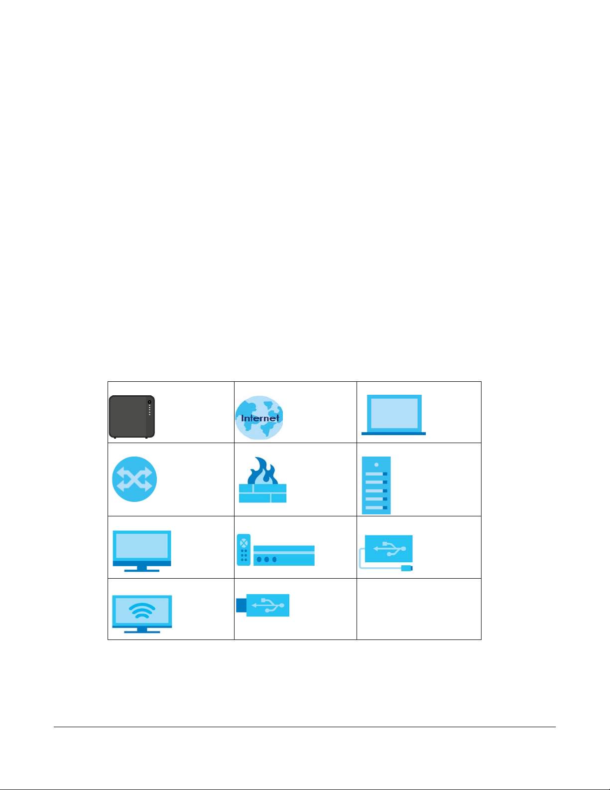
Icons Used in Figures
Figures in this user guide may use the following generic icons. The NAS icon is not an exact
representation of your device.
NAS Internet Laptop Computer
Switch Firewall Server
Desktop Computer Media Player USB Storage Drive
TV USB Hard Drive
NAS Series User’s Guide
3
Page 4

Contents Overview
Contents Overview
Get to Know Your NAS ......................................................................................................................... 13
Find and Access Your NAS .................................................................................................................. 18
Web Configurator ................................................................................................................................. 26
Video Tutorials ....................................................................................................................................... 37
Storage Manager ................................................................................................................................. 41
Control Panel: Overview .................................................................................................................... 101
Control Panel: Privilege and Sharing ................................................................................................ 104
Control Panel: Network ...................................................................................................................... 129
Control Panel: System ........................................................................................................................ 147
Control Panel: Service ........................................................................................................................ 158
Control Panel: Maintenance ............................................................................................................ 177
Status Center ....................................................................................................................................... 196
App Center and Packages ............................................................................................................... 199
Download Service .............................................................................................................................. 236
Upload Manager ................................................................................................................................ 252
Backup Planner .................................................................................................................................. 267
File Browser, Photo, Music & Video ................................................................................................... 292
Access Your Cloud Remotely via myZyxelCloud and Zyxel Drive App ........................................ 304
Play Media Files on TVs Using zCloud App ...................................................................................... 316
Troubleshooting .................................................................................................................................. 322
NAS Series User’s Guide
4
Page 5

Table of Contents
Table of Contents
Document Conventions ............................................ ................................................ ... .......................3
Contents Overview .............................................................................................................................4
Table of Contents.................................................................................................................................5
Chapter 1
Get to Know Your NAS.......................................................................................................................13
1.1 Overview ......................................................................................................................................... 13
1.2 LEDs .................................................................................................................................................. 14
1.3 Hard Disks ........................................................................................................................................ 15
1.4 SD Card ............................................................................................................................................ 15
1.5 Power Button ................................................................................................................................... 15
1.6 COPY/SYNC Button ........................................................................................................................ 16
1.7 RESET Button .................................................................................................................................... 16
Chapter 2
Find and Access Your NAS ...............................................................................................................18
2.1 Overview ......................................................................................................................................... 18
2.2 FindMe ............................................................................................................................................. 18
2.3 NAS Starter Utility ............................................................................................................................. 19
2.3.1 NAS Seeker Screen ............................................................................................................... 19
2.3.2 Main NAS Starter Utility Screen ............................................................................................ 20
2.3.3 Directory of the NAS ............................................................................................................. 22
2.3.4 Network Drive ........................................................................................................................ 22
2.3.5 Configure System Settings .................................................................................................... 23
Chapter 3
Web Configurator...............................................................................................................................26
3.1 Overview ......................................................................................................................................... 26
3.2 Access the NAS Web Configurator .............................................................................................. 26
3.3 Desktop ........................................................................................................................................... 30
3.3.1 Status Zone ............................................................................................................................. 33
3.3.2 Switch between Desktop Pages ......................................................................................... 33
3.3.3 Group Icons ........................................................................................................................... 34
3.3.4 Move Icons ............................................................................................................................ 36
Chapter 4
Video Tutorials....................................................................................................................................37
4.1 Overview ......................................................................................................................................... 37
NAS Series User’s Guide
5
Page 6

Table of Contents
4.2 Create a volume and copy files using Windows Explorer ......................................................... 37
4.3 Enable Time Machine on the NAS and your Mac computer .................................................... 37
4.4 Back up files to the NAS using Windows File History .................................................................... 39
4.5 Restore a backup using Windows File History .............................................................................. 40
4.6 Remotely access files on the NAS using WebDAV ..................................................................... 40
Chapter 5
Storage Manager...............................................................................................................................41
5.1 Overview ......................................................................................................................................... 41
5.2 Storage Manager Overview ........................................................................................................ 41
5.2.1 Internal Volumes Screen ...................................................................................................... 41
5.2.2 External Volumes Screen ...................................................................................................... 43
5.3 Internal Storage ............................................................................................................................. 43
5.3.1 Volume Screens .................................................................................................................... 45
5.3.2 Disk Group Screens ............................................................................................................... 70
5.3.3 Hard Disk Screens ................................................................................................................. 74
5.4 iSCSI LUNs Screens .......................................................................................................................... 80
5.4.1 Create a New LUN ................................................................................................................ 82
5.4.2 iSCSI Targets Screens ........................................................................................................... 84
5.5 External Storage .............................................................................................................................. 94
5.5.1 What You Need to Know ..................................................................................................... 94
5.5.2 External Storage Screens ...................................................................................................... 94
5.5.3 Format the External Volume ................................................................................................ 96
5.6 Technical Reference ...................................................................................................................... 97
Chapter 6
Control Panel: Overview .................................................. .... ................................................ ...........101
6.1 Overview ....................................................................................................................................... 101
6.2 Control Panel Overview .............................................................................................................. 101
Chapter 7
Control Panel: Privilege and Sharing .................................. ... ................................................ .... ....104
7.1 Overview ....................................................................................................................................... 104
7.2 What You Can Do ........................................................................................................................ 104
7.3 Users ............................................................................................................................................... 104
7.3.1 Users Screen ........................................................................................................................ 106
7.3.2 Add an Account ................................................................................................................. 107
7.3.3 Edit an Account .................................................................................................................. 111
7.3.4 User Info ................................................................................................................................ 112
7.4 Groups ........................................................................................................................................... 113
7.4.1 Groups Screen .................................................................................................................... 113
7.4.2 Add a Group ....................................................................................................................... 114
7.4.3 Edit a Group ........................................................................................................................ 118
NAS Series User’s Guide
6
Page 7

Table of Contents
7.4.4 Group Information .............................................................................................................. 119
7.5 Shared Folders .............................................................................................................................. 120
7.5.1 Share and Folder Names ...................................................................................................120
7.5.2 Shared Folders Screen ....................................................................................................... 120
7.5.3 Add a Share ......................................................................................................................... 122
7.5.4 Edit a Share .......................................................................................................................... 126
7.5.5 Shared Folder Information ................................................................................................. 127
7.5.6 Recycle Bin Screen ............................................................................................................. 128
Chapter 8
Control Panel: Network .................................. ... .... .... ... ................................................ .... ...............129
8.1 Overview ....................................................................................................................................... 129
8.2 What You Can Do ........................................................................................................................ 129
8.3 What You Need to Know ............................................................................................................. 129
8.4 TCP/IP Screens .............................................................................................................................. 130
8.4.1 Configure General TCP/IP Settings ................................................................................... 130
8.4.2 Configure Network Interface ............................................................................................. 131
8.4.3 Configure Web Configurator ............................................................................................. 136
8.4.4 Configure Network Diagnosis ............................................................................................ 137
8.5 UPnP Port Mapping Screens ........................................................................................................ 138
8.5.1 UPnP and the NAS’s IP Address ......................................................................................... 139
8.5.2 UPnP and Security ............................................................................................................... 140
8.5.3 The NAS’s Services and UPnP ............................................................................................. 140
8.5.4 Configure UPnP Router ....................................................................................................... 140
8.5.5 Configure UPnP Port Mapping .......................................................................................... 141
8.6 Terminal Screen ........................................................................................................................... 144
8.7 DyDNS Screen .............................................................................................................................. 145
Chapter 9
Control Panel: System................................................................................. ... ..................................147
9.1 Overview ....................................................................................................................................... 147
9.2 What You Can Do ........................................................................................................................ 147
9.3 What You Need to Know ............................................................................................................. 147
9.4 Server Name Screen ................................................................................................................... 148
9.5 Date/Time Screen ......................................................................................................................... 149
9.5.1 Configure Date/Time .......................................................................................................... 149
9.5.2 Configure Daylight Saving Time ........................................................................................ 150
9.6 FW Upgrade Screens ................................................................................................................... 151
9.6.1 Latest Firmware Check ....................................................................................................... 151
9.6.2 Manual Firmware Upgrade ................................................................................................ 152
9.7 SSL Screens ................................................................................................................................... 153
9.7.1 Install System CA ................................................................................................................. 153
9.7.2 Modify the Existing Certificate ........................................................................................... 154
NAS Series User’s Guide
7
Page 8

Table of Contents
9.7.3 Create a Certificate ........................................................................................................... 155
Chapter 10
Control Panel: Service............................................... ... ................................................ .... ...............158
10.1 Overview ..................................................................................................................................... 158
10.2 What You Can Do ...................................................................................................................... 158
10.3 What You Need to Know ........................................................................................................... 158
10.4 Media Server Screens .............................................................................................................. 159
10.4.1 Media Server Share Publish Screen ............................................................................... 160
10.5 iTunes Server Screen .................................................................................................................. 161
10.6 FTP Screens .................................................................................................................................. 162
10.6.1 General Settings ................................................................................................................ 162
10.6.2 Transfer Settings ................................................................................................................. 163
10.6.3 Character Set .................................................................................................................... 165
10.7 WebDAV Screen ......................................................................................................................... 165
10.7.1 How to Use NetDrive with the NAS .................................................................................. 166
10.8 Web Publishing Screens ............................................................................................................. 167
10.8.1 Status .................................................................................................................................. 167
10.8.2 Share Publish ...................................................................................................................... 168
10.8.3 How to Configure Web Publishing .................................................................................. 169
10.9 Print Server Screen ..................................................................................................................... 171
10.9.1 Print Server Edit .................................................................................................................. 172
10.10 Syslog Server Screen ................................................................................................................ 172
10.11 Technical Reference ................................................................................................................ 174
10.11.1 Share Media Files on Your Network .............................................................................. 174
10.11.2 Web Publishing ................................................................................................................ 175
10.11.3 Printer Sharing .................................................................................................................. 176
Chapter 11
Control Panel: Maintenance...........................................................................................................177
11.1 Overview ..................................................................................................................................... 177
11.2 What You Can Do ...................................................................................................................... 177
11.3 Power Screens ............................................................................................................................ 177
11.3.1 Power Management ........................................................................................................177
11.3.2 Power On/Off Schedule ...................................................................................................179
11.3.3 Add the Power Control Schedule .................................................................................. 180
11.4 Log Screen ................................................................................................................................. 181
11.4.1 Log Report Configuration Screen ................................................................................... 182
11.4.2 Email Setting ...................................................................................................................... 183
11.4.3 Report Setting .................................................................................................................... 184
11.4.4 Syslog Server Setting ......................................................................................................... 184
11.5 Configuration Backup Screens ................................................................................................ 185
11.5.1 Configuration Backup ...................................................................................................... 185
NAS Series User’s Guide
8
Page 9

Table of Contents
11.5.2 Configuration Restore ...................................................................................................... 186
11.5.3 Factory Reset ..................................................................................................................... 187
11.6 Technical Reference .................................................................................................................. 188
11.6.1 Log Classes ........................................................................................................................ 189
11.6.2 Log Severity Levels ............................................................................................................ 189
11.6.3 Log Messages .................................................................................................................... 189
Chapter 12
Status Center....................................................................................................................................196
12.1 Overview ..................................................................................................................................... 196
12.1.1 System Information ........................................................................................................... 196
12.1.2 Network .............................................................................................................................. 197
Chapter 13
App Center and Packages.............................................................................................................199
13.1 About Packages ......................................................................................................................... 199
13.1.1 Available Packages .......................................................................................................... 199
13.2 App Center Screens ................................................................................................................... 200
13.2.1 Installed Applications ....................................................................................................... 201
13.2.2 Application Update .......................................................................................................... 203
13.2.3 Browse All Apps ................................................................................................................. 204
13.3 AuroraSyncBackup ..................................................................................................................... 205
13.3.1 How to check video backups ......................................................................................... 207
13.4 DropboxClient ............................................................................................................................. 208
13.4.1 Configure Account Setting .............................................................................................. 209
13.4.2 How to associate NAS share/account with Dropbox account ................................... 211
13.4.3 Configure Update Period .................................................................................................215
13.5 GoogleDriveClient ..................................................................................................................... 216
13.5.1 Configure Account Setting .............................................................................................. 216
13.5.2 How to link NAS account, share and Google account ............................................... 218
13.5.3 Configure Update Period ................................................................................................221
13.6 NFS ............................................................................................................................................... 222
13.6.1 Add/Edit NFS Share ........................................................................................................... 224
13.6.2 NFS Session ......................................................................................................................... 226
13.7 PHP-MySQL-phpMyAdmin ......................................................................................................... 227
13.8 TFTP .............................................................................................................................................. 228
13.9 pyLoad ......................................................................................................................................... 230
13.10 Memopal ................................................................................................................................... 231
13.10.1 Memopal Status .............................................................................................................. 231
13.10.2 Memopal Settings ........................................................................................................... 232
13.11 ownCloud .................................................................................................................................. 234
Chapter 14
Download Service................. .... ... .... ................................................ ................................................236
NAS Series User’s Guide
9
Page 10

Table of Contents
14.1 Overview ..................................................................................................................................... 236
14.2 What You Need to Know ........................................................................................................... 236
14.3 Download Service Screen ......................................................................................................... 236
14.3.1 Add a Download Task ...................................................................................................... 239
14.3.2 Configure General Download Settings .......................................................................... 240
14.3.3 Configure the P2P Download Settings ........................................................................... 242
14.3.4 Configure the IP Filter Settings ......................................................................................... 244
14.3.5 Configure the Email notifications Settings ...................................................................... 245
14.3.6 Select Files to Download .................................................................................................. 246
14.3.7 Display the Task Information ............................................................................................246
14.4 Download Notify Screen ............................................................................................................ 248
14.5 Technical Reference .................................................................................................................. 249
14.5.1 Download Service ............................................................................................................. 249
14.5.2 P2P Download Security .................................................................................................... 250
Chapter 15
Upload Manager..............................................................................................................................252
15.1 Overview ..................................................................................................................................... 252
15.2 What You Can Do ...................................................................................................................... 252
15.3 What You Need to Know ........................................................................................................... 252
15.4 Flickr/YouTube Screen ............................................................................................................... 253
15.4.1 Configure the Flickr Settings ............................................................................................. 253
15.4.2 Configure the YouTube Settings ...................................................................................... 259
15.5 FTP Uploadr Screen ..................................................................................................................... 261
15.5.1 Add or Edit an FTP Server Entry ........................................................................................ 263
15.5.2 FTP Uploadr Preferences Screen ..................................................................................... 263
Chapter 16
Backup Planner................................................................................................................................267
16.1 About Backups ........................................................................................................................... 267
16.1.1 Manage a USB Device and USB Backups ...................................................................... 267
16.1.2 Remote Backups ............................................................................................................... 267
16.1.3 Internal Backups ................................................................................................................ 267
16.1.4 Cloud Backups .................................................................................................................. 267
16.1.5 Synchronize Files ................................................................................................................ 268
16.2 What You Can Do ...................................................................................................................... 268
16.3 Backup Screens .......................................................................................................................... 268
16.3.1 Add a new backup job ....................................................................................................270
16.3.2 Edit Job Screens ................................................................................................................ 276
16.3.3 Restore Screens ................................................................................................................. 280
16.4 Copy/Sync Button Screens ........................................................................................................ 286
16.4.1 Configure Copy Settings .................................................................................................. 286
16.4.2 Sync Settings ...................................................................................................................... 287
NAS Series User’s Guide
10
Page 11

Table of Contents
16.4.3 How to Copy Files ............................................................................................................. 288
16.4.4 How to Synchronize Files .................................................................................................. 289
16.5 Time Machine Screen ................................................................................................................ 290
Chapter 17
File Browser, Photo, Music & Video ................................................................................................292
17.1 Overview ..................................................................................................................................... 292
17.2 File Browser ................................................................................................................................. 292
17.3 Photo ............................................................................................................................................ 294
17.3.1 Exif and Google Maps (Photos) ...................................................................................... 297
17.3.2 Slideshow (Photos) ............................................................................................................ 298
17.4 Music ............................................................................................................................................ 298
17.4.1 Now Playing (Music) ......................................................................................................... 300
17.5 Video ............................................................................................................................................ 300
17.6 Playzone Settings ........................................................................................................................ 302
17.7 Application Zone ........................................................................................................................ 303
Chapter 18
Access Your Cloud Remotely via myZyxelCloud and Zyxel Drive App.....................................304
18.1 myZyxelCloud Service ................................................................................................................ 304
18.1.1 myZyxelCloud Screen ....................................................................................................... 304
18.1.2 Pair your NAS ..................................................................................................................... 305
18.1.3 DDNS Setup ........................................................................................................................ 307
18.1.4 NAS Information ................................................................................................................ 308
18.1.5 UPnP Setup ......................................................................................................................... 309
18.2 Zyxel Drive .................................................................................................................................... 309
18.2.1 Zyxel Drive Welcome ........................................................................................................ 310
18.2.2 NAS and File List ................................................................................................................. 310
18.2.3 Uploading and Media Streaming ................................................................................... 311
18.2.4 Instant Upload ................................................................................................................... 312
Chapter 19
Play Media Files on TVs Using zCloud App... ... .... .... ... ................................................ .... .... ...........316
19.1 Using zCloud ................................................................................................................................ 316
19.2 zCloud TV Streaming .................................................................................................................. 317
19.3 zCloud Instant Upload ............................................................................................................... 319
Chapter 20
Troubleshooting................................................................................................................................322
20.1 Troubleshooting Overview ......................................................................................................... 322
20.2 Power, Hardware, Connections, and LEDs .............................................................................. 322
20.3 NAS Starter Utility ......................................................................................................................... 324
20.4 NAS Login and Access ............................................................................................................... 325
NAS Series User’s Guide
11
Page 12

Table of Contents
20.4.1 Enabling Scripting of Safe ActiveX Controls .................................................................. 326
20.5 I Cannot Access The NAS .......................................................................................................... 328
20.6 Users Cannot Access the NAS ................................................................................................... 329
20.7 External USB Drives ...................................................................................................................... 330
20.8 Storage ........................................................................................................................................ 330
20.9 Firmware ...................................................................................................................................... 331
20.10 File Transfer ................................................................................................................................ 331
20.11 Networking ................................................................................................................................ 332
20.12 Some Features’ Screens Do Not Display ................................................................................ 332
20.13 Media Server Functions ............................................................................................................ 333
20.14 Download Service Functions ................................................................................................... 335
20.15 Web Publishing .......................................................................................................................... 335
20.16 Auto Upload .............................................................................................................................. 336
20.17 App Center ............................................................................................................................... 337
20.18 Backups ..................................................................................................................................... 337
20.19 Google Drive ............................................................................................................................. 338
Appendix A Customer Support ..................................................................................................... 339
Appendix B Product Specifications.............................................................................................. 345
Appendix C Legal Information ...................................................................................................... 346
Index.................................................................................................................................................350
NAS Series User’s Guide
12
Page 13

1.1 Overview
This User’s Guide covers the following models: NAS326, NAS520, NAS540, and NAS542.
Table 1 NAS Series Comparison Table
FEATURES NAS326 NAS520 NAS540 NAS542
RAM Size 512 MB DDR III 1 GB DDR III 1 GB DDR III 1 GB DDR III
Number of Hard Disk Bays 2 2 4 4
Supported RAID Types RAID0
Number of Ethernet Ports 1 2 2 2
Port Trunking Support No Yes Yes Yes
Number of USB Ports 2 (USB3.0)
Number of SD Card Slots N/A 1 1 1
CHAPTER 1
Get to Know Your NAS
RAID1
JBOD
BASIC
1 (USB2.0)
RAID0
RAID1
JBOD
BASIC
3 (USB3.0) 3 (USB3.0) 3 (USB3.0)
RAID0
RAID1
RAID5
RAID6
RAID10
JBOD
BASIC
RAID0
RAID1
RAID5
RAID6
RAID10
JBOD
BASIC
Use the NAS as your own personal cloud. Here are some key features:
• Start using Zyxel NAS instantly with FindMe - Use Zyxel FindMe to discover your NAS on your home
network and get in control in under 15 seconds. Then do an easy installation with no need to install a
NAS utility.
• Access and share files from your NAS wherever you are - Using the Zyxel Drive mobile app makes it
easy.
• Create a shared cloud space for people without a NAS - Provide your cloud space for your friends or
family members when you share a folder from the NAS with the Zyxel Drive mobile app. Your friends
and family members don’t need to purchase an additional NAS - just install the Zyxel Drive mobile
app on their mobile devices.
• Protect your data from drive failure - The NAS’s RAID 1 capability clones contents from one drive to
another. If a drive is damaged or corrupted, you still have another drive to restore from or use.
• Get up and running quickly with the easy-to-use in terface - The Zyxel NSM (NAS Station Management)
5.2 intelligent desktop provides a rich feature set of tools with an easy-to-understand GUI design to
help you get things done quickly. The multitasking capability through a multi-window interface
enables you to quickly get applications up and running.
• Check your NAS while you’re away - Even if you have several Zyxel NAS devices, visit the
myZyxelcloud Web portal from anywhere to see their health status at a glance.
• Stream multimedia contents to your big screen TV - Bring your favorite multimedia files on the NAS to
the big screen. Zyxel zCloud app lets you play your favorite videos, music, or photos on your big
screen with TV streaming devices such as Apple TV, Google Chromecast, Roku 3, and Amazon Fire TV;
or directly on smart TVs like those from Samsung and LG.
NAS Series User’s Guide
13
Page 14
Chapter 1 Get to Know Your NAS
NAS
A
B
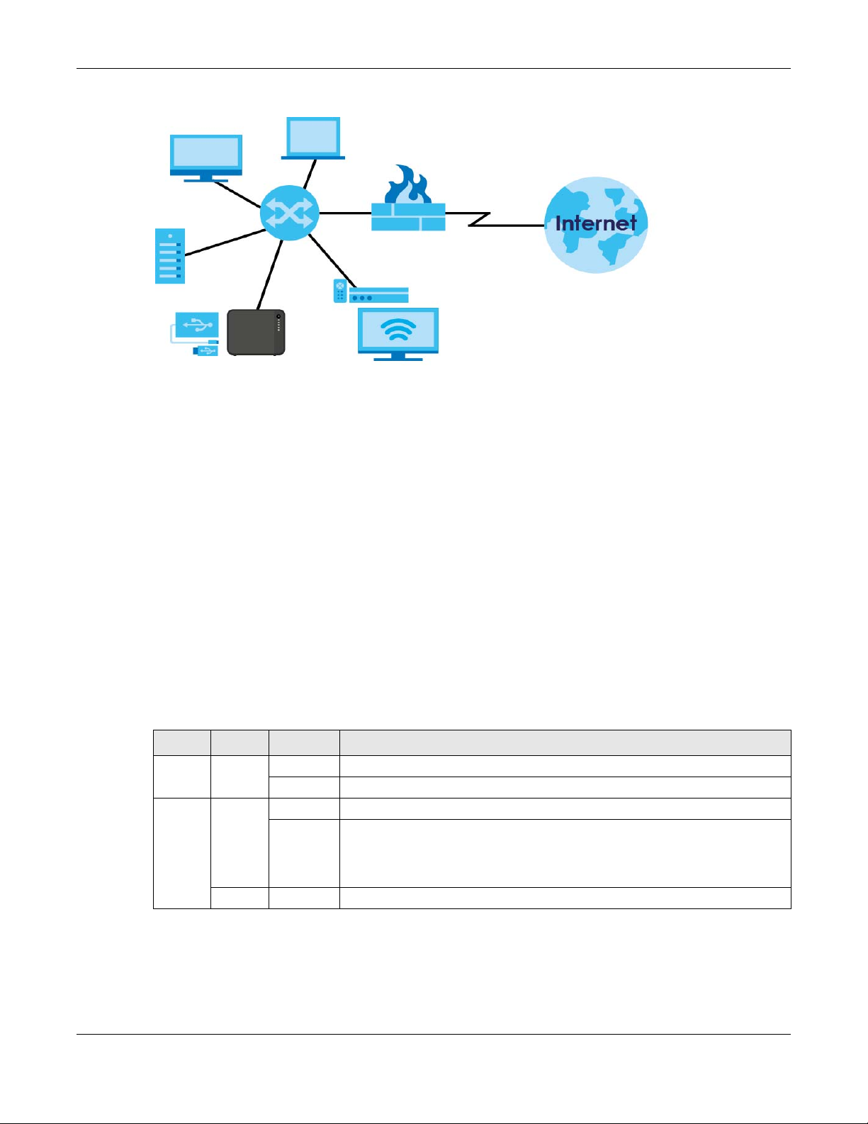
Figure 1 Example of the NAS in a Home Network
Above is the NAS in a home network. Users back up and share data on the NAS. The media player (A)
plays the NAS’s media files on the TV. A USB hard drive (B) provides extra storage space and files are
copied directly from the USB storage device to the NAS.
Place the NAS behind a firewall and/or IDP (Intrusion Detection and Prevention) device to protect it
from attacks from the Internet.
Refer to the Quick Start Guide for hardware connections and how to install and remove hard drives from
the disk trays.
Note: Turn off and disconnect the NAS before you install or remove the internal hard disk or
1.2 LEDs
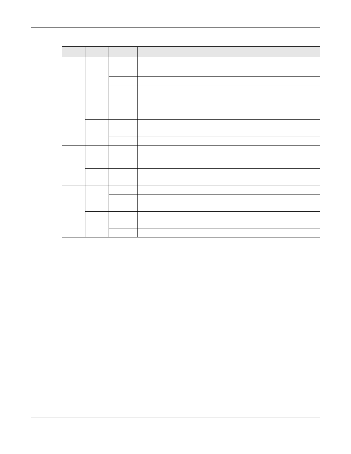
This table describes the NAS’s LEDs.
Table 2 LEDs
LED COLOR STATUS DESCRIPTION
POWER White On The NAS is turned on and receiving power, or in the process of starting up.
SYSTEM White On The NAS has fully started and is operating normally.
disks.
Off The NAS is turned off.
Blinking The NAS is starting up or upgrading the firmware.
Note: Do not turn off the NAS while it is upgrading the firmware or you
may render it unusable.
Red On The NAS has a system error.
NAS Series User’s Guide
14
Page 15
Chapter 1 Get to Know Your NAS
Table 2 LEDs (continued)
LED COLOR STATUS DESCRIPTION
HDD1/2 White On The hard disk drive is connected properly to the NAS. This LED stays on white
when the hard disk drive is in hibernation if you do not enable sleeping HDD LED
blinking.
Blinking The NAS is saving data to the hard disk drive.
Slow
Blinking
Red On The NAS detected an error on the hard disk drive (like a bad sector for example).
Off The NAS cannot detect a hard disk in the disk bay or the LED is disabled.
USB White On The NAS has a USB device installed.
Off There is no USB device installed or the NAS does not detect a USB connection.
COPY White On A USB or SD device is connected to the NAS and the NAS is ready to copy.
Blinking The NAS is copying or synchronizing files, or in the process of pairing with a
Red On Copying or synchronizing files to or from the USB or SD failed.
Off No USB/SD device is connected.
LAN /
LAN1 /
LAN2
Green On The NAS has a successful 10/100 Mbps Ethernet connection.
Blinking The 100M LAN is sending or receiving packets.
Off The NAS does not have a 10/100 Mbps Ethernet connection.
Amber On The NAS has a successful 1000 Mbps Ethernet connection.
Blinking The 1000 M LAN is sending or receiving packets.
Off The NAS does not have a 1000 Mbps Ethernet connection.
Sleeping HDD LED blinking is enabled and the hard disk drive is in hibernation.
The NAS automatically tries to recover a bad sector, but the LED stays red until
the NAS restarts.
myZyxelcloud account.
1.3 Hard Disks
The NAS has internal hard disk bays. Install SATA (Serial Advanced Technology Attachment) hard disks.
Note that the SATA hard disks are treated as internal or SATA volumes. Any hard disk connected to a USB
port is considered an external or USB volume.
1.4 SD Card
Use up to a 128 GB SDXC card with the front panel SD card slot. The SD card slot works with the COPY/
SYNC button (see Section 1.6 on page 16 for details).
1.5 Power Button
Use the power button on the front panel to turn the NAS on or off.
NAS Series User’s Guide
15
Page 16

Chapter 1 Get to Know Your NAS
Press
1 Beep
2 Beeps
2 more seconds
Release for
3 seconds
Release for
software
shutdown
hardware
shutdown
Press
1 Beep
2 Beeps
IP Address
Password
Clear All Settings
5 more seconds
Release to
Release to Reset
Power On
• Press the power button for one second to turn on the NAS. When the system is on and ready, you will
hear one beep.
Power Off
Figure 2 Using the Power Button to Turn Off the NAS
• To have the NAS go through its normal software shutdown process and turn itself off, press the power
button until you hear one beep (after about three seconds), then release it.
• To perform a hardware shutdown and have the NAS immediately turn itself off without going through
the normal shutdown process, press the power button until you hear a second beep (after about five
seconds), then release it.
1.6 COPY/SYNC Button
Use the COPY/SYNC button on the front panel to copy or synchronize files between a connected USB or
SD device and the NAS. See Section 16.4 on page 286 for more details on how to configure the copy/
sync settings.
1.7 RESET Button
Use the RESET button on the rear panel to restore the NAS’s default settings.
Figure 3 The RESET Button
• Press the RESET button until you hear one beep (after about two seconds), then release it. You will
hear one more beep after you release the button.
This resets the NAS’s IP address and password to the default values.
NAS Series User’s Guide
16
Page 17

Chapter 1 Get to Know Your NAS
• Press the RESET button until you hear two beeps. After the second beep, continue pressing the button
for five more seconds, then release it. You will hear three quick beeps after you release the button.
This resets the NAS to the factory default configuration. All settings you have configured on the NAS,
including IP address, password, user accounts, groups, and so on will be reset to the factory defaults.
The reset process does NOT affect the volume settings, nor data stored on the NAS.
You should periodically back up your configuration file to your computer (see Section 11.5 on page 185
for details about managing the NAS’s configuration file). You could then restore your configuration in
the event that you or someone else reset the NAS to the factory defaults.
Note: Keep the NAS in a secure location in order to prevent unauthorized reset of the device.
You may need to close and re-open the NAS Starter Utility to discover the NAS. This is because the NAS
automatically re-acquires IP address information, so its IP address may change. If no IP address
information is assigned, the NAS uses Auto-IP to assign itself an IP address and subnet mask. For example,
you could connect the NAS directly to your computer. If the computer is also set to get an IP address
automatically, the computer and the NAS will choose addresses for themselves and be able to
communicate.
NAS Series User’s Guide
17
Page 18
Find and Access Your NAS
2.1 Overview
Use FindMe or the NAS Starter Utility to find and access the NAS and the files on it.
The NAS Starter Utility supports Windows XP, Windows Vista, Windows 7, and Windows 8. Click Help to
open a Web Help page about the NAS Starter Utility screens.
Note: Installing this version of the NAS Starter Utility uninstalls previous versions.
Note: Refer to the Quick Start Guide for your NAS’s hardware connections.
2.2 FindMe
CHAPTER 2
1 Make sure both the NAS and your computer are connected to a switch or router with Internet access.
2 Open your web browser and type "https://findme.zyxel.com" as the website address.
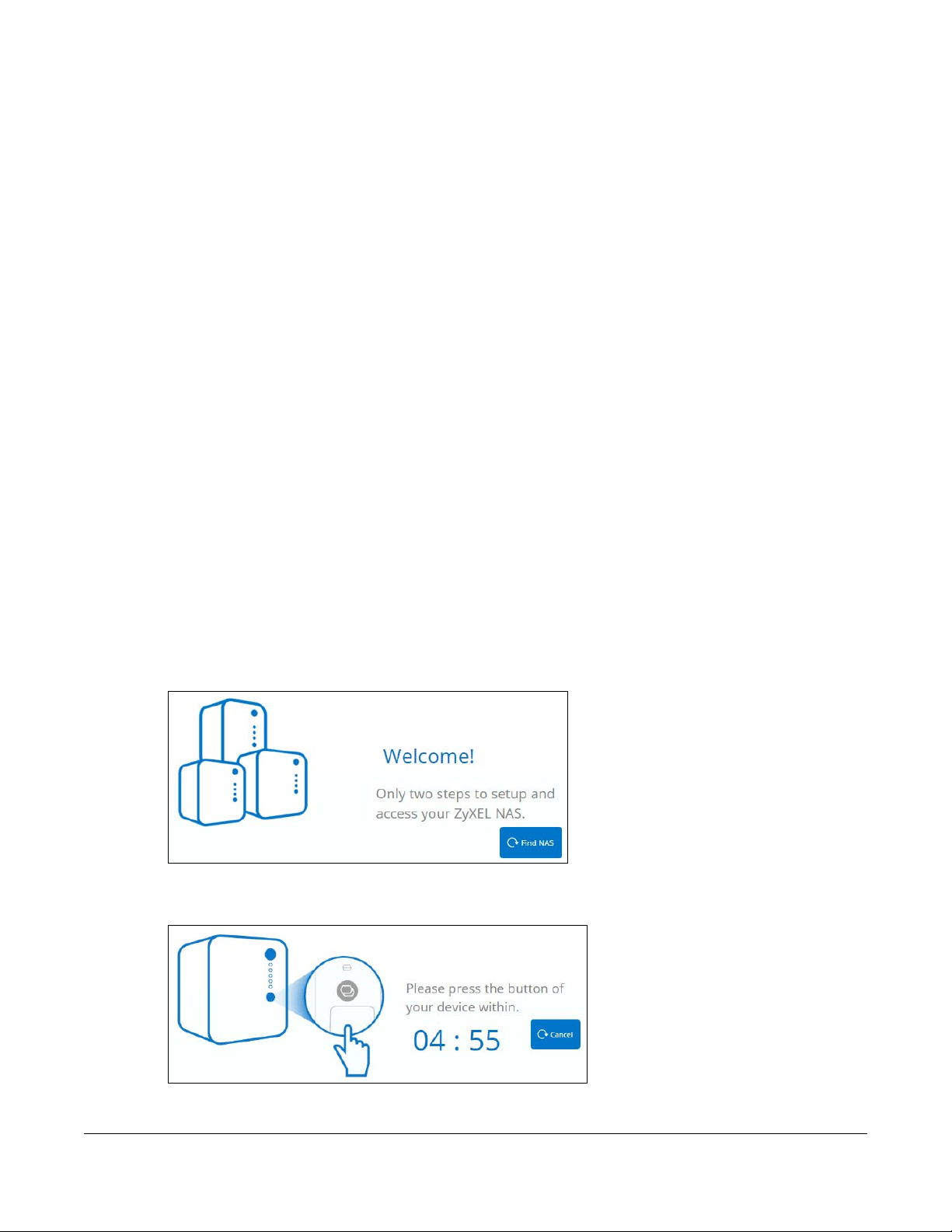
3 Click Find NAS to discover your NAS.
Figure 4 Find NAS
4 Press the Copy button on the NAS within 5 minutes.
Figure 5 Press the Copy button
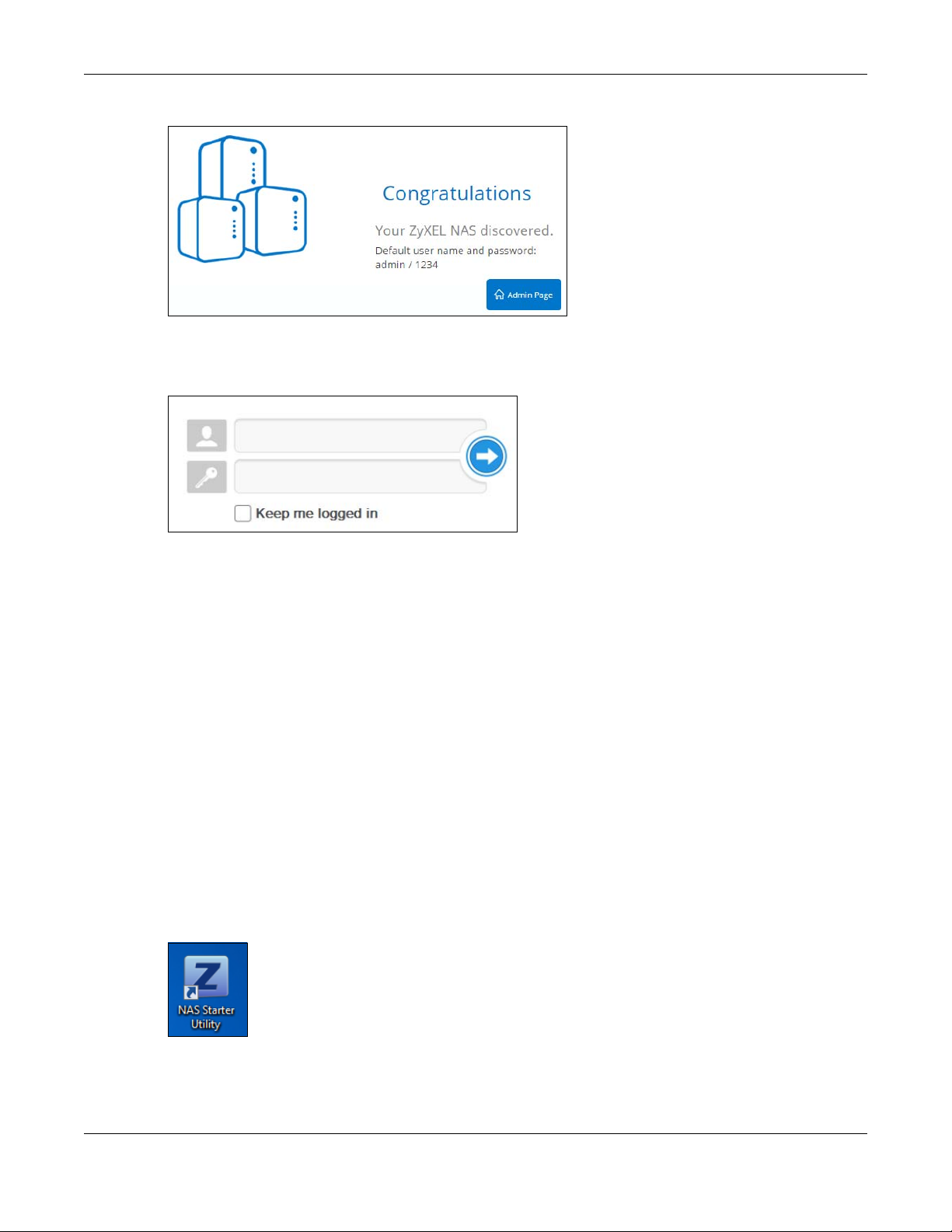
5 Your NAS is now discovered. Click Admin Page to open the login screen.
NAS Series User’s Guide
18
Page 19
Chapter 2 Find and Access Your NAS
Figure 6 Congratulations
6 Use the default username “admin” and password “1234” to log in. See Chapter 3 on page 26 for more
on the web desktop.
Figure 7 NAS Login Screen
2.3 NAS Starter Utility
• The NAS Starter Utility broadcasts a request packet when you first run it. Each NAS has an NAS Starter
Utility Agent that always listens and responds to requests from the NAS Starter Utility. The NAS Starter
Utility receives the response packet that contains information, such as host name, IP, and so on.
• If you plan to use more than one NAS in your network, configure them with unique server names. This
enables you to identify each NAS in the NAS Starter Utility screens.
2.3.1 NAS Seeker Screen
Use this screen to view the NASs in your network. The NAS’s Server Name. The default is ‘NAS’ followed by
the number of your model (‘NAS540’ for example). See Section 2.3.5 on page 23 for how to change it to
a more recognizable one in your network.
Click the NAS Starter Utility icon on your desktop or in the Windows system tray to start the NAS Starter
Utility. Alternatively you can click Start > Programs > Zyxel > NAS Starter Utility.
Figure 8 NAS Starter Utility Desktop Icon
NAS Series User’s Guide
19
Page 20
Chapter 2 Find and Access Your NAS
Figure 9 NAS Starter Utility Windows System Tray Icon
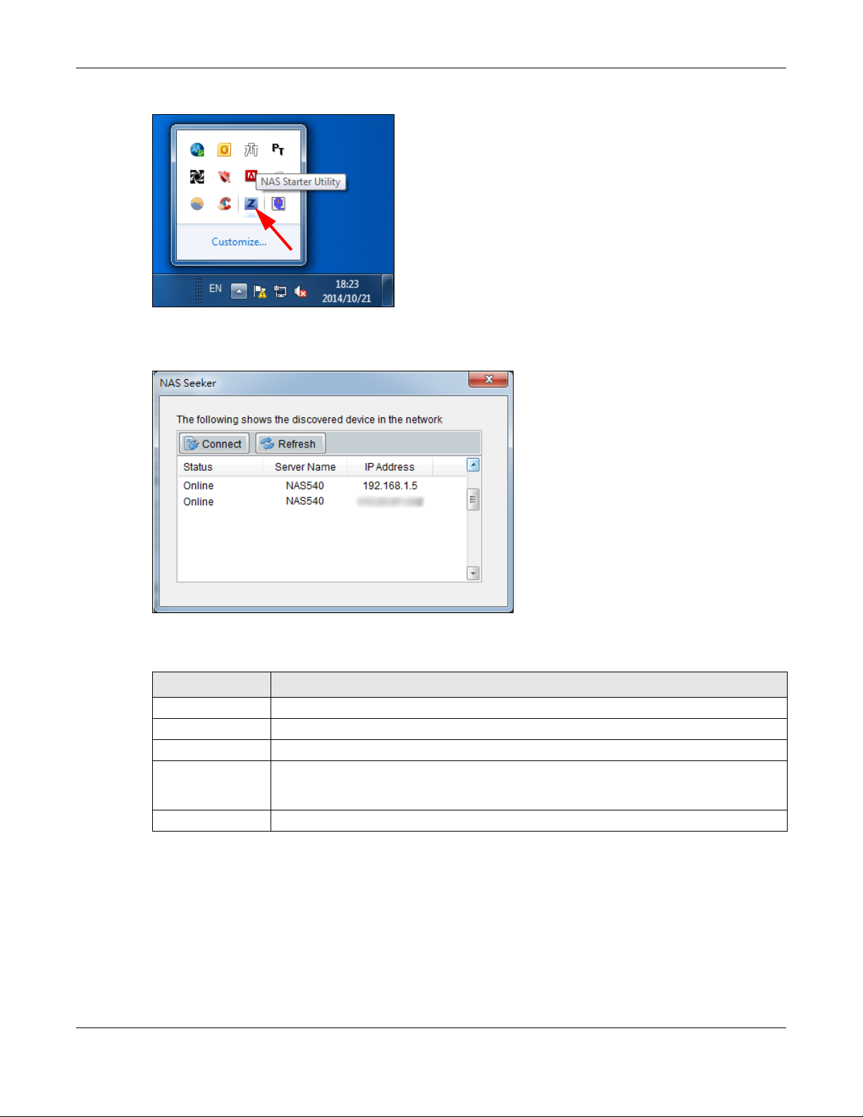
The first time you open the NAS Starter Utility the discovery screen appears as follows.
Figure 10 NAS Seeker
The following table describes the labels in this screen.
Table 3 NAS Seeker
LABEL DESCRIPTION
Connect Select a NAS and click this to connect to it.
Refresh Click this to refresh the screen. The NAS Starter Utility does not automatically refresh.
Status This shows whether the NAS is Online, Unreachable, Configuring, or Config Failed.
Server Name This is the server name you configured for the NAS. If you have more than one NAS in your
network, it is recommended that you give each one a unique name for identification
purposes.
IP Address This is the current IP address of the NAS.
2.3.2 Main NAS Starter Utility Screen
The main NAS Starter Utility screen displays after you select an NAS in the NAS Seeker screen.
NAS Series User’s Guide
20
Page 21
Chapter 2 Find and Access Your NAS
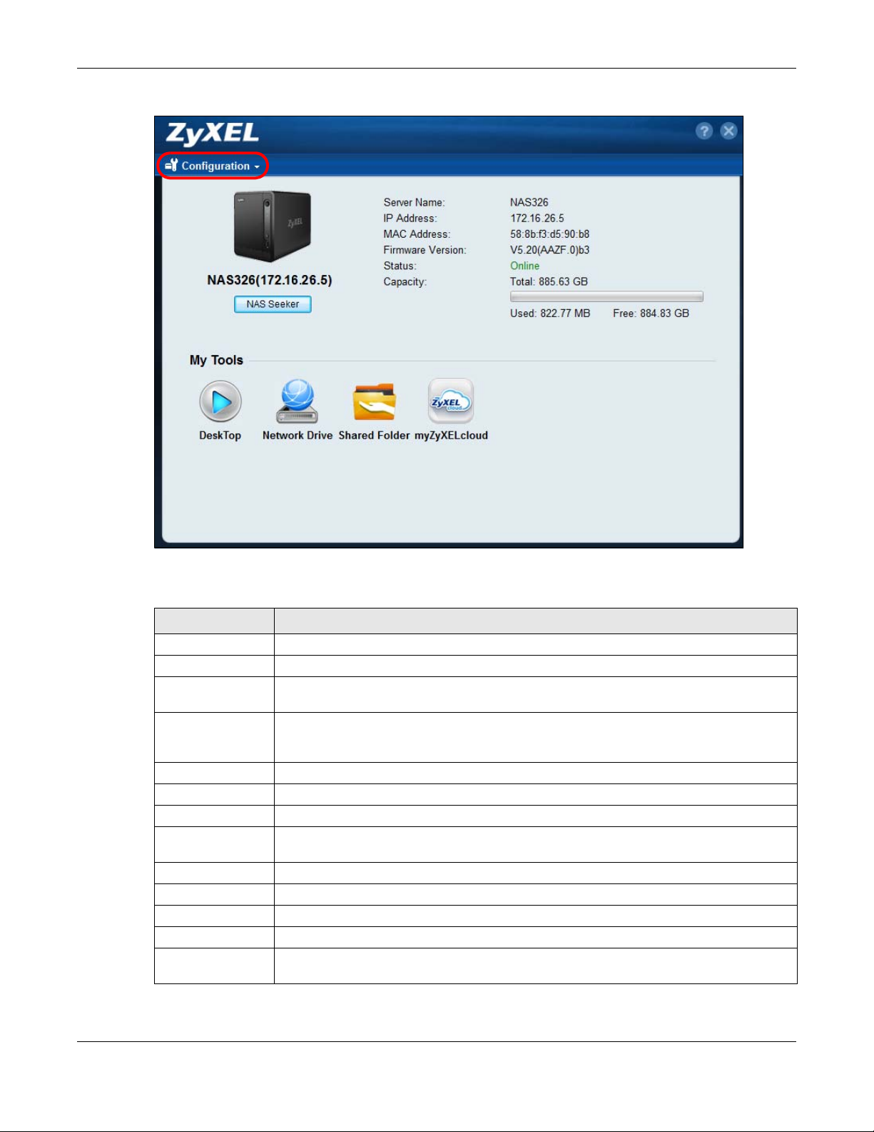
Figure 11 NAS Starter Utility Main Screen
The following table describes the labels in this screen.
Table 4 NAS Starter Utility Main Screen
LABEL DESCRIPTION
? Click this to display the utility help.
Configuration Click this to configure system settings (see Section 2.3.5 on page 23).
NAS Seeker Click this to use the NAS Seeker screen (see Section 2.3.1 on page 19) to find and connect to
a different NAS on your network.
Server Name This is the server name you configured for the NAS. If you have more than one NAS in your
network, it is recommended that you give each one a unique name for identification
purposes.
IP Address This is the current IP address of the NAS.
MAC Address This is the NAS’s unique physical hardware address (MAC).
Firmware Version This shows the version of firmware the NAS is currently using.
Status This shows whether the NAS is Online, Uninitialized, Unreachable, Configuring, or Config
Failed.
Capacity This shows the NAS’s total, in-use, and remaining storage capacity.
DeskTop Click this button to go to the Web Configurator login screen (see Section 3.2 on page 26).
Network Drive Click this to add the NAS as a network drive in your computer’s Windows Explorer.
Shared Folder Click this to log into the NAS’s file directory in Windows Explorer.
myZyxelCloud Click this to go to mycloud.zyxel.com to set up a free DDNS hostname for the NAS so you can
connect to it easily from the Internet.
NAS Series User’s Guide
21
Page 22
2.3.3 Directory of the NAS
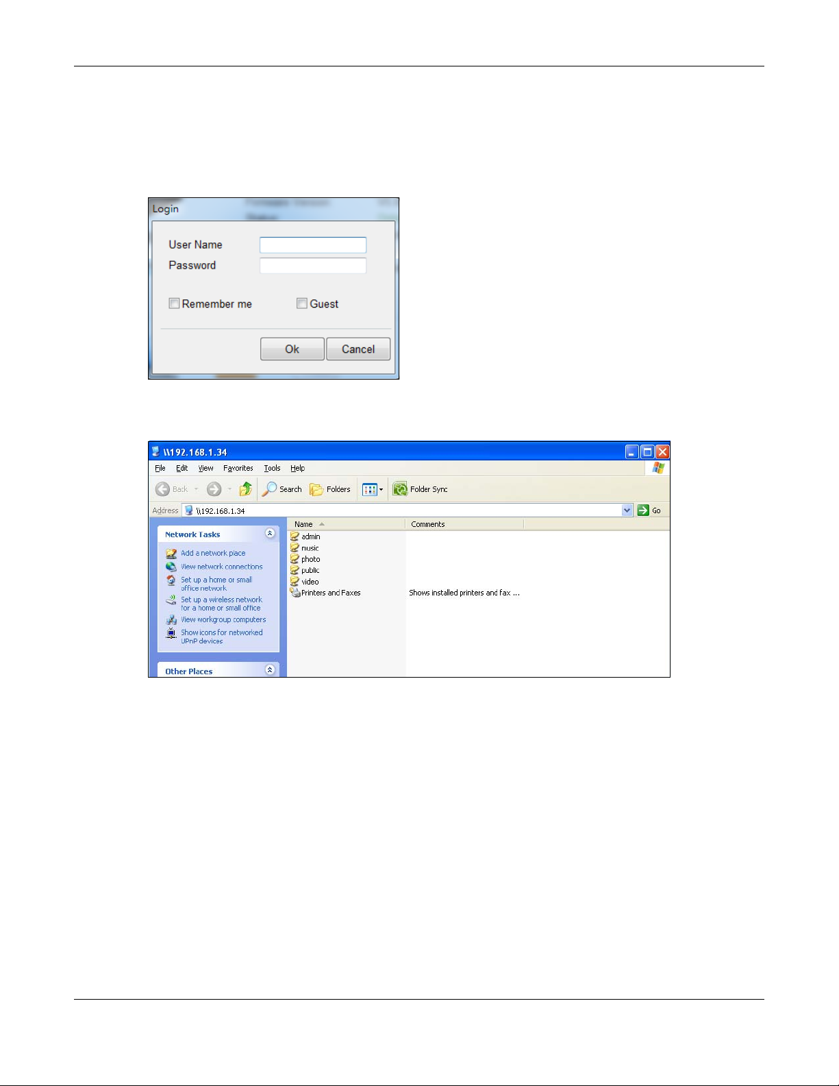
In the main NAS Starter Utility screen click Shared Folder to log into the NAS’s file directory in Windows
Explorer. Enter the administrator user name and password and click Login.
Figure 12 Login
The utility opens the NAS’s directory in Windows Explorer.
Figure 13 Directory
Chapter 2 Find and Access Your NAS
2.3.4 Network Drive
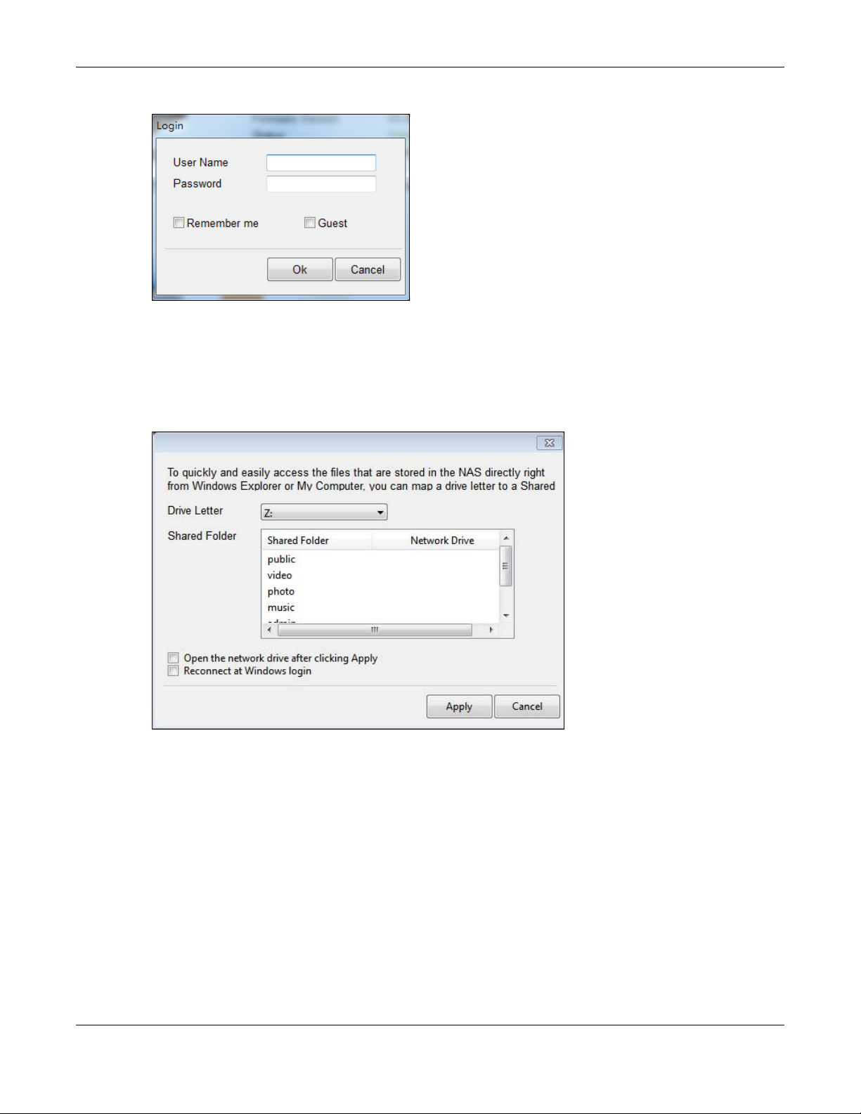
In the main NAS Starter Utility screen click Network Drive to add the NAS as a network drive in your
computer’s Windows Explorer.
Enter your user name and password and click Login to be able to add the NAS’s shares to which you
have access as network drives. Otherwise select Guest and click Login to be able to add the NAS’s
public shares as network drives.
NAS Series User’s Guide
22
Page 23
Chapter 2 Find and Access Your NAS
Figure 14 Login
Select a share on the NAS and the drive letter on your computer to which you want to map it. The shares
that each user can select to map depends on the user’s permissions. For example, if share1 is private to
user1, then only user1 is allowed to map share1. The table displays the NAS shares that are already
mapped to drive letters on your computer. After you click Apply you can see the new drive in Windows
Explorer (My Computer) where you can access and use it like your computer’s other drives.
Figure 15 Network Drive
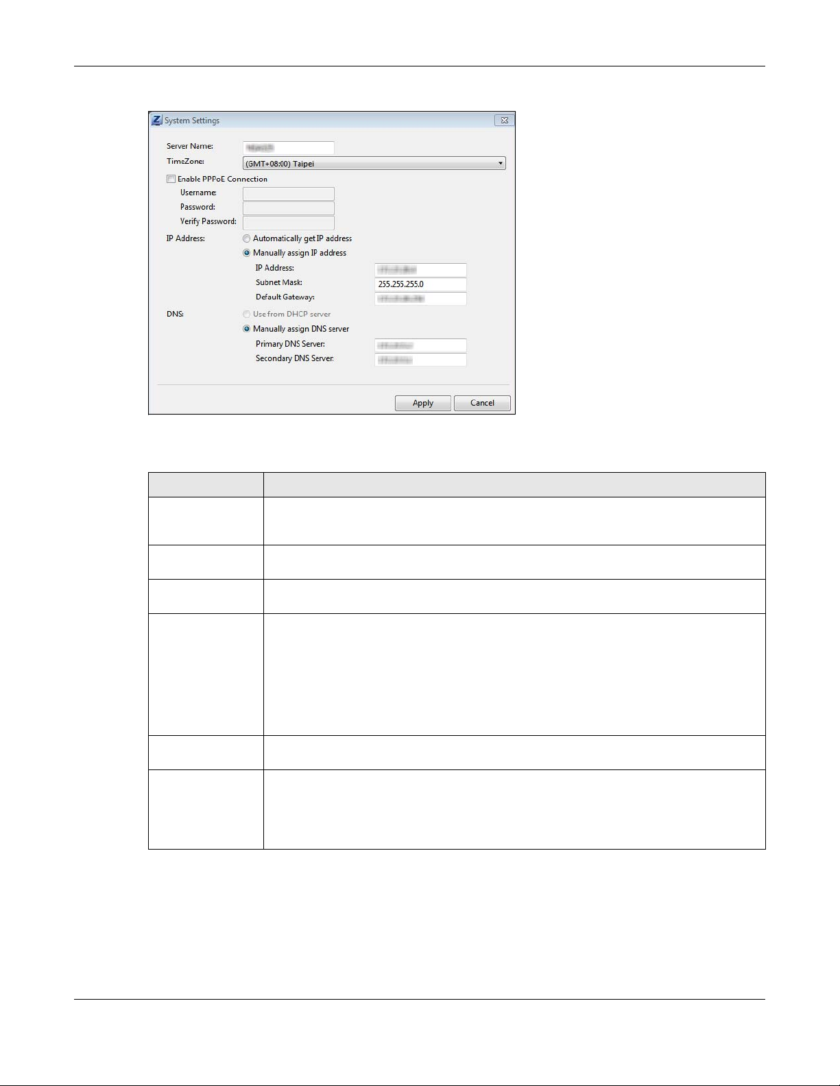
2.3.5 Configure System Settings
Use these screens to be able to change the NAS’s server name, time zone, PPPoE, IP address, subnet
mask, default gateway, or DNS settings.
Click Configuration > System Setting in the main utility screen to display the following screen.
NAS Series User’s Guide
23
Page 24
Chapter 2 Find and Access Your NAS
Figure 16 NAS Starter Utility > Configuration > System Setting
The following table describes the labels in this screen.
Table 5 NAS Starter Utility > Configuration > System Setting
LABEL DESCRIPTION
Server Name Specify a name to uniquely identify the NAS on your network. You can enter up to 15
Time Zone Choose the time zone of your location. This will set the time difference between your time
Enable PPPoE
Connection
IP Address Use these fields to configure the IP address of the LAN interface through which you are
Automatically get
IP address
Manually assign IP
address
alphanumeric characters with minus signs allowed but not as the last character. The name
must begin with an alphabetic character (a-z) and is case sensitive.
zone and Greenwich Mean Time (GMT).
Click this if your Internet connection requires you to enter a user name and password to
connect to the Internet. Enter your user name and password
connected to the NAS.
When the LAN interfaces are set to stand-alone, this configures the IP address of the LAN
interface in the same subnet as your computer. It configures LAN1 if both LAN interfaces are
in the same subnet as your computer.
If you use the administrator configuration screens to set the LAN interfaces to link
aggregation, this configures the IP address that both LAN interfaces share.
Select this if the NAS is automatically assigned an IP address from the ISP or a DHCP server in
your network.
Select this if you want to assign the NAS a fixed IP address, subnet mask and default
gateway.
Note: Do not configure an IP address that is already in use in your network. This
results to a network IP address conflict and makes the NAS inaccessible.
NAS Series User’s Guide
24
Page 25
Chapter 2 Find and Access Your NAS
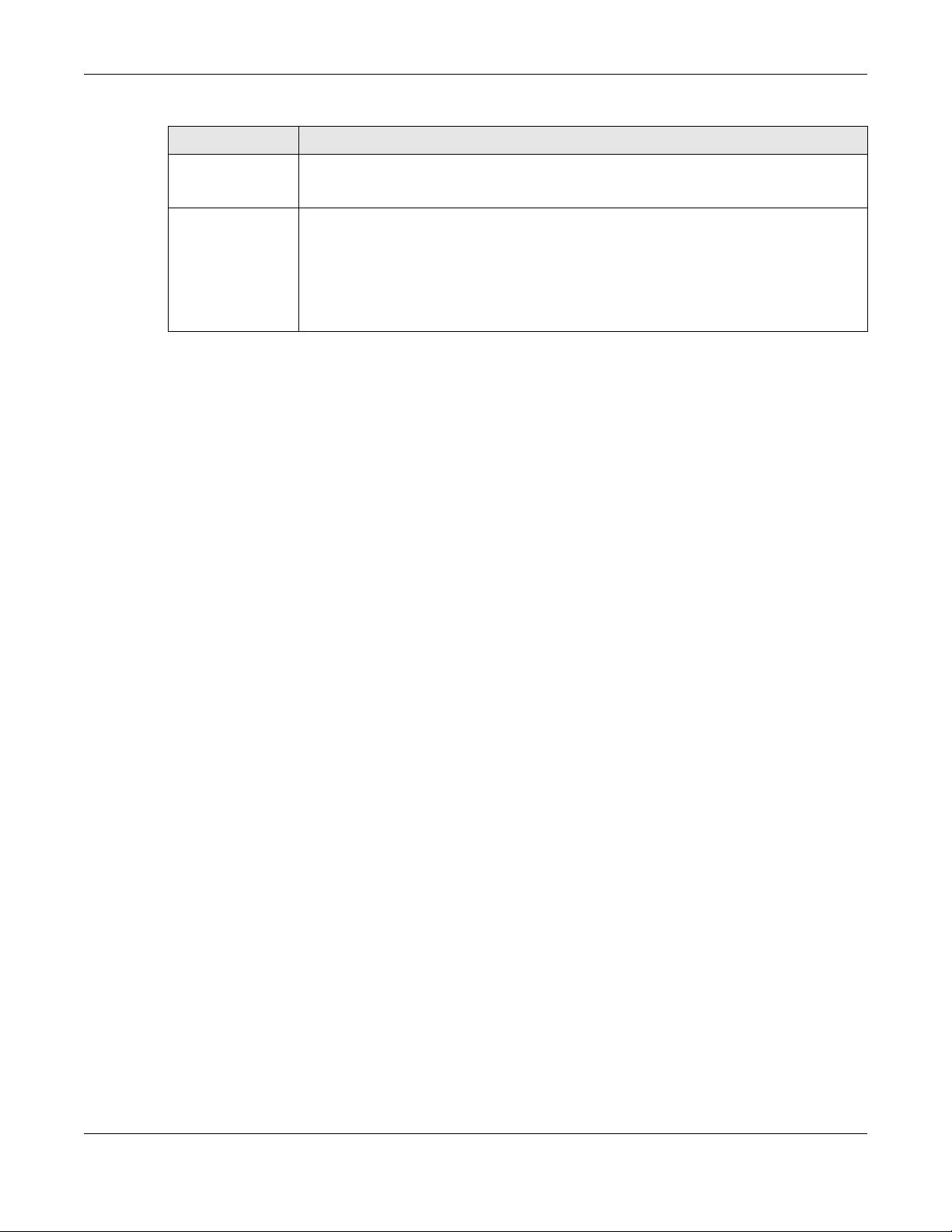
Table 5 NAS Starter Utility > Configuration > System Setting (continued)
LABEL DESCRIPTION
Use from DHCP
server
DNS Domain Name System (DNS) is for mapping a domain name to its corresponding IP address
Domain Name System (DNS) is for mapping a domain name to its corresponding IP address
and vice versa. Select this if the NAS is automatically given DNS information from the ISP or a
DHCP server in your network.
and vice versa.
Select Use from DHCP server if the NAS is automatically given DNS information from the ISP or
a DHCP server in your network.
Select Manually assign DNS server if you were given specific IP address(es) of the DNS
server(s). Enter the primary and secondary DNS in the corresponding fields.
NAS Series User’s Guide
25
Page 26
3.1 Overview
This chapter describes how to access the NAS web configurator and provides an overview of its screens.
The web configurator is an HTML-based management interface that allows easy NAS setup and
management using an Internet browser.
Use Internet Explorer 11.0.9, Mozilla Firefox 31.0, Safari 5.1.7, Google Chrome 37.0.2, or later versions of
these browsers. The recommended screen resolution is 1440 by 900 pixels or higher.
In order to use the web configurator you need to allow:
• Web browser pop-up windows from your device. Web pop-up blocking is enabled by default in
Windows XP SP (Service Pack) 2.
• JavaScript (enabled by default).
CHAPTER 3
Web Configurator
3.2 Access the NAS Web Configurator
This guide uses the NAS326 screens as an example. The screens may vary slightly for different models.
1 Make sure your NAS is properly connected and that your computer is in the same subnet as the NAS
(refer to the Quick Start Guide or the appendices).
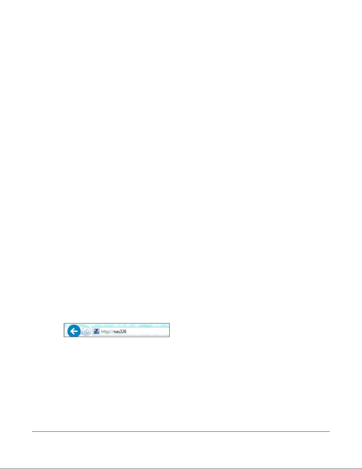
Open your web browser and type in the server name of the NAS. The default is “nas” followed by the
number of your model (“nas326” for example). Configure the server name of your NAS using the Control
Panel > System > Server Name screen (Section 9.4 on page 148) or the System Setting screen (Section
2.3.5 on page 23) of the NAS Starter Utility.
Figure 17 NAS URL
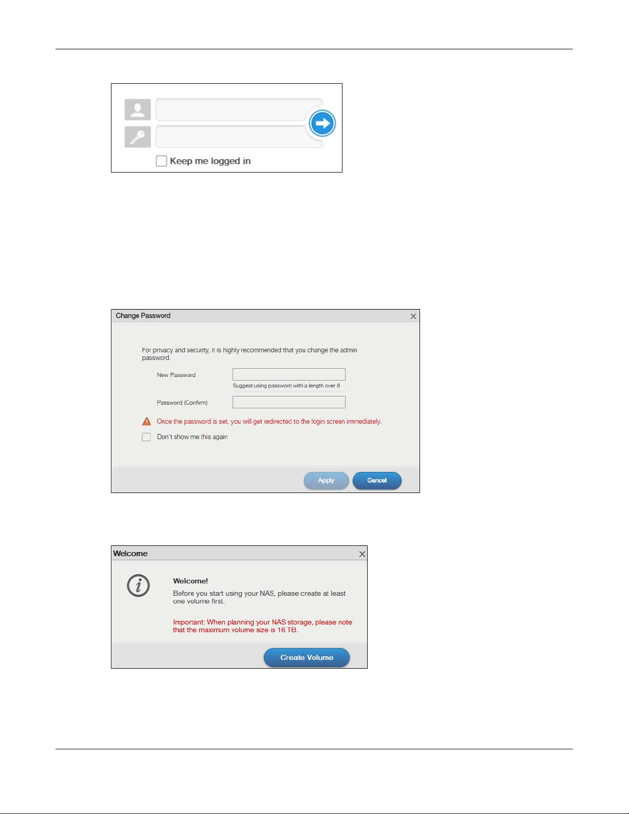
2 The default user name and password are “admin” and “1234” respectively. Enter your user name and
password. See Chapter 7 on page 104 for how to create other user accounts. If you use the option to
stay logged in (assuming you do not log out), make sure you keep your computer secure from
unauthorized access. Click the arrow to log in. Logging in with a (non-administrator) user account takes
you to a different Desktop screen (see Section 3.3 on page 30 for details).
NAS Series User’s Guide
26
Page 27
Chapter 3 Web Configurator
Figure 18 NAS Login Screen
Make sure you have a backup of any existing data in the hard disk
before installing it in the NAS. Creating a volume formats the hard disk
and deletes all data in the process.
3 You should see a screen asking you to change your password (highly recommended) as shown next.
Type a new password in the New Password field. Retype the password for confirmation in the Password
(Confirm) field. Click Cancel if you do not want to change the password this time. Click Apply to save
your changes back to the NAS.
Figure 19 Change Default Password Screen
4 This screen displays if you have not created a volume yet. Click Create Volume to make a volume or
click the x to close the screen to go to the Desktop (Section 3.3 on page 30).
Figure 20 Welcome Screen
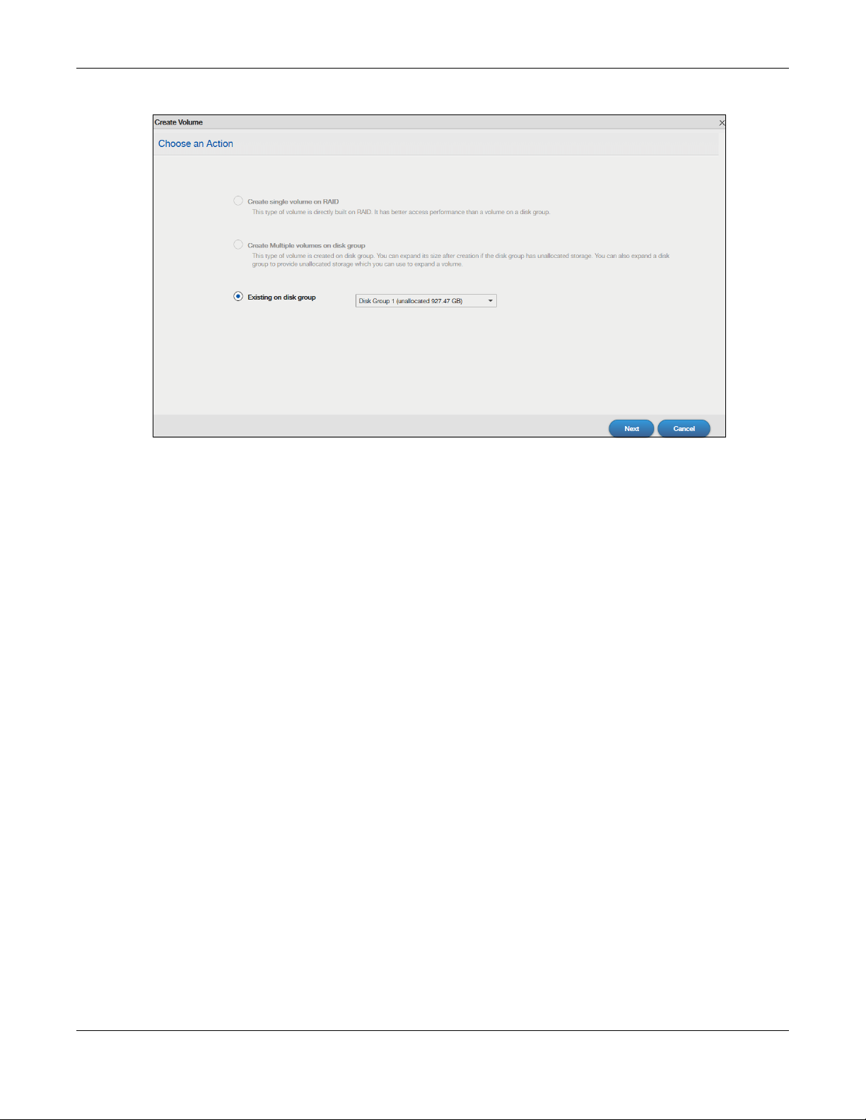
5 Select Create single volume on RAID for a simple set up. Go to Section 5.3.1.1 on page 49 for details.
Select Create Multiple volumes on disk group to be able to create more than one storage volume. Go
to Section 5.3.1.7 on page 62 for details.
NAS Series User’s Guide
27
Page 28
Chapter 3 Web Configurator
Figure 21 Create Volume
If you choose Existing on disk group, you will go to the screens below after clicking Next.
NAS Series User’s Guide
28
Page 29
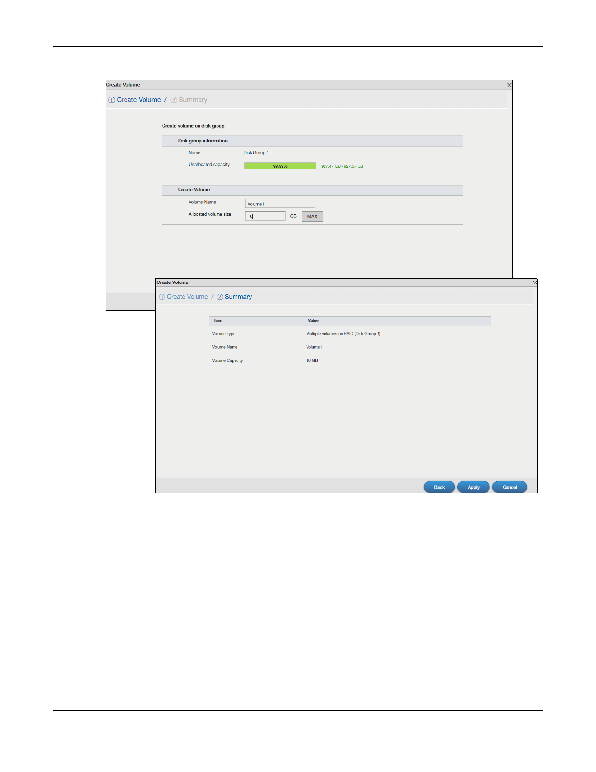
Figure 22 Existing on Disk Group
Chapter 3 Web Configurator
If this is the first time the NAS has created a volume, it needs to reboot after the volume is created. Click
Yes to reboot or No to go to the Desktop.
NAS Series User’s Guide
29
Page 30
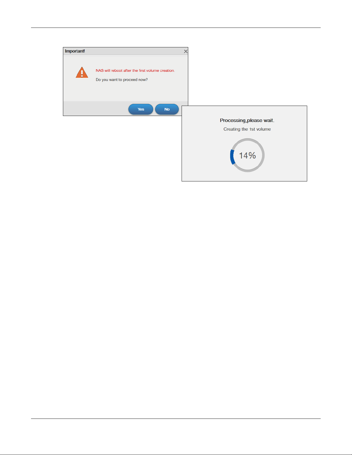
Figure 23 Reboot
Chapter 3 Web Configurator
3.3 Desktop
The Desktop screen displays after you log in. Hover your mouse over the heading bar icons to display
their names.
NAS Series User’s Guide
30
Page 31

Chapter 3 Web Configurator
Status Zone
1
2
34
5
6
7
8
91011
2019
12
13
14
15
16 17
18
21
22
Figure 24 Desktop (Administrator)
Figure 25 Desktop (User)
NAS Series User’s Guide
31
Page 32

Chapter 3 Web Configurator
Note: The Web Configurator session automatically times out if left idle for 15 minutes. Simply
log back into the NAS if this happens to you.
1 Desktop - click this to minimize all windows so you can see the desktop. Click it again to restore the
windows to their previous state.
2 Storage Manager- click this to open the storage configuration screens to display the status of both
internal and external storage, and configure disk groups, volumes, and iSCSI functions.
3 Control Panel - click this to open the control panel screens to configure user’s access privileges, network,
system, media services and maintenance settings.
4 Status Center - click this to display NAS system information or network connection status.
5 App Center - click this to discover, install and update applications which packed in the NAS.
6 Download Service - click this to configure download settings and view download details.
7 Upload Manager - click this to upload files to FTP servers, your Flickr and YouTube accounts.
8 Backup Planner - click this to set up your backup plan, restore backups, configure copy and
synchronous settings or turn Time Machine support on.
9 Help - click this to display the NAS’ embedded help system screens.
10 File Browser - click this to see files in a tree-folder structure.
11 Photo - click this to view photos in the shares that publish photos.
12 Music - click this to view and play music files in the shares that publish music.
13 Video - click this to view and play video files in the shares that publish videos.
14 myZyxelCloud - click this to open a screen to set up myZyxelCloud service.
15 Video Tutorial - click this to view Zyxel’s youtube videos, which show you how to use the NAS.
16 Knowledge Base - click this to visit Zyxel product support website and find articles related to product
applications, FAQ, and user experience.
17 Twonky Media Player - click this to open the Twonky media server configuration screens to check media
server status or modify media server settings.
18 Eject NAS External Drives - click this to eject the connected external volumes.
19 Language - this displays current language using by the NAS. Click to select the language you want to
use to configure the Web Configurator.
20 User - click this to restart, shutdown, log out and change your user account password.
21 Playzone Settings - click this to open the playzone configuration screen in a new tab.
22 Application Zone - click this to open the application zone in a new tab.
NAS Series User’s Guide
32
Page 33

3.3.1 Status Zone
The Status Zone displays icons for various features you can access.
Table 6 Status Zone Icons
ICON DESCRIPTION
Chapter 3 Web Configurator
Click System Status to open the Status Center screen. System Status displays the health state of the
NAS. A green circle with a check mark indicates healthy.
User Type displays the current number of web sessions. Click this to go to the Status Center >
Network screen for more details.
CPU displays what percentage of the NAS’s processing capability is currently being used. RAM
displays what percentage of the NAS’s memory is currently being used. Click this to open the Status
Center > System Information screen for more details.
Click this to select widgets to show on the status bar.
Select or clear the widgets to show or hide on the Status bar. Click OK to save your changes or
Cancel to exit this screen without saving changes.
Click this to hide or show the status bar.
3.3.2 Switch between Desktop Pages
Click the dot to move between multiple desktop pages. A white dot indicates the current page. The
maximum number of the desktop pages is five.
NAS Series User’s Guide
33
Page 34

Chapter 3 Web Configurator
Figure 26 Switch between Desktop Pages
3.3.3 Group Icons
You can drag one icon to another one and make them a group as shown below.
NAS Series User’s Guide
34
Page 35

Figure 27 Group Icons
Chapter 3 Web Configurator
After the group is created, the default group name is “NewGroup”. You can click the icon to change
the group name. In the following example, the group name is changed to Media.
Figure 28 Change the Group Name
You can also move the group to another page by right-clicking the icon as shown next.
NAS Series User’s Guide
35
Page 36

Figure 29 Move the Group Location
3.3.4 Move Icons
You can move an icon to another page by right-clicking the icon as shown next.
Figure 30 Move the Icon Location
Chapter 3 Web Configurator
NAS Series User’s Guide
36
Page 37

4.1 Overview
Click Video Tutorial on the Desktop to go to www.youtube.com to view Zyxel’s youtube videos, which
show you how to use the NAS. This chapter provides information about the following tutorials.
• Create a volume and copy files using Windows Explorer, see page 37
• Enable Time Machine on the NAS and your Mac computer, see page 37
• Back up files to the NAS using Windows File History, see page 39
• Restore a backup using Windows File History, see page 40
• Remotely access files on the NAS using WebDAV, see page 40
Note: Screens and graphics in the video may differ slightly from your product due to
differences in your product firmware or your computer operating system.
CHAPTER 4
Video Tutorials
4.2 Create a volume and copy files using Windows Explorer
After you find and log into the NAS, you must create a volume to start using the NAS. You can then use
Windows Explorer to copy files from your computer to the NAS.
Creating a volume formats the hard disk and deletes all data in the
process. Make sure you have a backup of any existing data in the hard
disk before installing it in the NAS.
See https://www.youtube.com/watch?v=_-WeIgHdxwA&index=1&list=PL-69xFi03dP9zQn8gHGcVwf-
X6ShkNU27 for the related Zyxel youtube video.
4.3 Enable Time Machine on the NAS and your Mac computer
Time Machine is a backup system provided by Mac OS X. It automatically backs up everything on your
Mac, including pictures, music, videos, documents, applications, and settings. This tutorial helps you to
enable Time Machine in OS X to use your NAS as a backup volume.
Use the Backup Planner > Time Machine screen (Section 16.5 on page 290) to turn Time Machine
support on or off, and designate a share for Time Machine backups.
NAS Series User’s Guide
37
Page 38

Chapter 4 Video Tutorials
After enabling Time Machine on the NAS, follow the steps below to set up Time Machine on your Mac to
use your NAS for backup.
You can also see https://www.youtube.com/watch?v=nzpZNJuEsUs&index=2&list=PL-
69xFi03dP9zQn8gHGcVwf-X6ShkNU27 for the related Zyxel youtube video.
1 Click Apple > System Preferences. Then go to System and select Time Machine.
2 Turn Time Machine ON. Then click Change Disk.
3 Select the share you designated on the NAS as the backup disk (share01 in this example). Then click Use
for Backup.
NAS Series User’s Guide
38
Page 39

Chapter 4 Video Tutorials
4 When prompted for the username and password of share01, enter the login information for an existing
user account with write access permission on share01 (for information on configuring user accounts and
shares see Chapter 7 on page 104). In this example user1/12345 is used. Then click Connect.
5 Time Machine starts backing up files to share01 after 120 seconds. If you want to back up immediately,
click the Time Machine icon and select Back Up Now.
6 The screen shows the status of the backup once the process begins.
7 To stop the backup process, click the Time Machine icon and select Stop Backing Up. Then turn Time
Machine OFF.
4.4 Back up files to the NAS using Windows File History
File History is a Windows backup tool which was original introduced in Windows 8. You can set up File
History in your Windows computer to automatically back up your files to a connected NAS.
NAS Series User’s Guide
39
Page 40

Chapter 4 Video Tutorials
See https://www.youtube.com/watch?v=xt1XdMAZisU&list=PL-69xFi03dP9zQn8gHGcVwf-
X6ShkNU27&index=3 for how to use File History in Windows 10 to back up files from a computer to the
NAS.
4.5 Restore a backup using Windows File History
If you used Windows File History to back up files from your computer to the NAS, File History also allows
you to restore the backup.
See https://www.youtube.com/watch?v=xt1XdMAZisU&list=PL-69xFi03dP9zQn8gHGcVwf-
X6ShkNU27&index=3 for how to use File History in Windows 10 to restore files from a backup.
4.6 Remotely access files on the NAS using WebDAV
If your computer is not connected to the NAS’s local network, WebDAV allows you to use client
programs that support WebDAV to remotely edit and manage files stored on the NAS.
In this example, you need to:
1 Click Control Panel > Service > WebDAV to enable WebDAV on your NAS (see Section 10.7 on page
165).
2 Click the myZyxelcloud icon on the desktop to create a myZyxelcloud account at https://
mycloud.zyxel.com.
3 Pair the NAS and the myZyxelcloud account.
4 Set up a free DDNS host name for the NAS so you can connect to it easily from the Internet.
5 Configure UPnP port mapping to allow access from the WAN (Internet) to the WebDAV services on the
NAS.
6 Install a client program that supports WebDAV (NetDrive for example) on the computer from which you
want to remotely access files stored on the NAS.
See https://www.youtube.com/watch?v=Z9oxXx1rZAA&index=5&list=PL-69xFi03dP9zQn8gHGcVwf-
X6ShkNU27 for the Zyxel youtube video.
NAS Series User’s Guide
40
Page 41

Storage Manager
5.1 Overview
This chapter displays the status of both internal and external storage, and introduces how to configure
disk groups, volumes, and iSCSI functions. After you log in with an administrator account, click Storage
Manager on the Desktop to go to the following screens in a new window.
5.2 Storage Manager Overview
Click Storage Manager on the Desktop to display the status of both internal and external storage, and
configure disk groups, volumes, and iSCSI functions.
The Storage Manager Overview screen displays the status, current storage configuration and volume
usage of internal volumes and capacity usage of external volumes.
CHAPTER 5
5.2.1 Internal Volumes Screen
Figure 31 Storage Manager > Overview > Internal Volumes
NAS Series User’s Guide
41
Page 42

Chapter 5 Storage Manager
The following table describes the labels in this screen.
Table 7 Storage Manager > Overview > Internal Volumes
LABEL DESCRIPTION
Storage The circular icon displays the overall health state of the NAS.
A green circle with a check mark indicates healthy.
An orange circle with an exclamation mark indicates attention. This appears when a
volume or disk group is degraded. Click Repair to repair it.
An red circle with an exclamation mark indicates danger. This appears when a
volume or disk group is crashed. You cannot recover the volume.
Volume on RAID This section shows the current storage usage for each volume built directly on top of a
RAID. These volumes have higher access performance than volumes on a disk group
but are less flexible in regards to size.
Details include the currently used percentage of the volume.
Shared Folder (Normal) - green on the circle represents the volume’s percentage of
used capacity in a healthy state.
LUN (Normal) - blue on the circle represents the iSCSI LUN’s percentage of used
capacity.
Degraded - orange on the circle represents the volume’s percentage of used
capacity in a degraded state. Degraded means one or more disks has failed but you
can still replace a faulty disk to recover the volume.
Crashed/Full - a red exclamation point represents the volume is in a down state.
Down means you cannot recover the volume. Full means the volume has run out of
space.
Available - gray on the circle represents the volume’s percentage of unused
capacity.
This section also displays the volume’s used capacity, and total capacity available.
Volume on Disk Group This section shows the current storage usage for each volume built on top of a disk
group. You can expand a volume’s size after creation if the disk group has
unallocated space. You can also expand a disk group by adding hard disks.
NAS Series User’s Guide
42
Page 43

Chapter 5 Storage Manager
5.2.2 External Volumes Screen
Figure 32 Storage Manager > Overview > External Volumes
The following table describes the labels in this screen.
Table 8 Storage Manager > Overview > External Volumes
LABEL DESCRIPTION
Volume Details include the currently used percentage of the volume.
5.3 Internal Storage
A volume is a basic storage space on the NAS. To store data on the NAS, you must create at least one
volume. Your NAS supports the following:
Used - green on the circle represents the volume’s percentage of used capacity in a
healthy state.
Full - a red exclamation point represents the volume has run out of space.
Unformatted - purple on the circle represents the connected USB storage device is not
formatted with a file system.
Unsupported - violet on the circle represents the connected USB storage device uses
a file system the NAS does not support.
Available - gray on the circle represents the volume’s percentage of unused
capacity.
This section also displays the volume’s used capacity, and total capacity available.
• Internal volumes (built on the hard disks installed in the NAS)
NAS Series User’s Guide
43
Page 44

Chapter 5 Storage Manager
• External volumes (built on the external storage devices attached to the NAS)
Internal Volumes
Table 9 Internal Volumes
OPTION DESCRIPTION
Volume Allocates all the available space to the volume.
Provides better performance.
Volume on Disk
Group
Allows you to create multiple volumes on a disk group.
Allows you to customize the size of a volume.
RAID Types
The following table describes RAID types.
Note: RAID 5, RAID 6, RAID 10, and the hot spare option apply to 4-bay NAS devices.
Table 10 RAID Types
RAID
TYPE
Basic 1 0 Use Basic with one disk. It has no fault tolerance. 1 x (HDD size)
JBOD 2-4 0 Use JBOD with two or more disks for maximum
RAID 0 2-4 0 Use RAID 0 with two or four disks for maximum
RAID 1 2-4 (No. of HDD) -1 Use RAID 1 to create an exact copy of data on
RAID 5 3-4 1 Use RAID 5 with three or four disks to balance
RAID 6 4 2 Use RAID 6 with four disks for more data
RAID 10 4 1 HDD in each RAID
NO. OF
HDD
NO. OF HDD
ALLOWED TO FAIL
1 group
DESCRIPTION CAPACITY
capacity. This is just a collection of disks with no
fault tolerance.
speed and no fault tolerance.
one disk to a second disk. Use this with two to
four disks to mirror primary data to another
disk(s) with high performance.
You can add a hot spare to a 2-disk RAID 1.
performance and hard disk capacity usage
with data protection in case of disk failure.
You can add a hot spare to a 3-disk RAID 5.
protection in case of disk failure.
Use RAID 10 with four disks to get better
performance than RAID 6, with slightly less data
protection.
sum of HDD sizes
sum of HDD sizes
Smallest HDD size
(No. of HDD – 1) x
(smallest HDD size)
(No. of HDD – 2) x
(smallest HDD size)
(No. of HDD / 2) x
(smallest HDD size)
Repair Volumes or Disk Groups
If a hard disk in a RAID 1 with a hot spare or a RAID 5 with a hot spare fails, the NAS automatically uses
the hot spare to re-build the volume or disk group. Later you can replace the failed hard disk and add
the new disk as a hot spare.
A hard disk failure in a RAID 1, RAID 5, RAID 6, or RAID 10 degrades the volume or disk group. Replace
the failed disk and use the Internal Storage screen’s Repair link to repair the volume.
NAS Series User’s Guide
44
Page 45

Chapter 5 Storage Manager
Change RAID Type
You can change the following RAID types without losing stored data. This can help you manage your
storage capacity as you add more disks.
Table 11 Internal Volumes
RAID TYPE WHAT YOU CAN CHANGE IT TO
Basic RAID 1
RAID 1 RAID 1 with a hot spare or RAID 5
RAID 5 RAID 5 with a hot spare or RAID 6
Expand Volumes or Disk Groups
As your content grows, you can do the following to expand the storage capacity of a volume or disk
group without losing stored data.
Table 12 Expand Volumes and Disk Groups
EXPANSION
METHOD
Using
unallocated disk
space
Adding disks You can add one or more disks to a JBOD, RAID 1 or RAID 5.
Replacing with
larger disks
DESCRIPTION
You can add more storage space to a volume if there is still some space unallocated on the
same disk group.
The hard disk you want to add must have capacity equal to or greater than the smallest disk in
the volume or disk group.
You can replace smaller disks in a RAID 1, RAID 5, or RAID 6 with larger disks.
Replace disks one-by-one.
Replace the smallest disk in the volume or disk group first.
After replacing a disk, you must use the Internal Storage screen’s Manage link to repair the
volume.
Wait for the repair process to complete before you replace another disk.
5.3.1 Volume Screens
Use the Volume screen to configure and manage internal volumes. From the Internal Storage screen,
click Volume to open the screen as shown.
NAS Series User’s Guide
45
Page 46

Chapter 5 Storage Manager
Figure 33 Internal Storage Volume
The following table describes the labels in this screen.
Table 13 Storage Manager > Internal Storage > Volume
LABEL DESCRIPTION
Volume
Use this section to configure and manage volumes built on hard disks directly.
Create Click this to format internal hard disks and create a new volume. All data on the disk(s) will
be lost.
Note: This button is not available while the NAS is creating, deleting, or changing
the RAID type of any volume or disk group.
A pop-up screen appears if all installed hard disks are used by other volumes or disk groups.
You will need to install another hard disk into the NAS if any disk tray is available or remove
unnecessary volumes or disk groups to release the storage space. Click OK to close this
screen.
Manage Select a volume and click Manage to edit, repair or expand the volume.
Note: This button is available only when you can repair, expand or change the
RAID type.
NAS Series User’s Guide
46
Page 47

Chapter 5 Storage Manager
Table 13 Storage Manager > Internal Storage > Volume (continued)
LABEL DESCRIPTION
Delete Click Delete to remove the selected volume. A pop-up screen displays. Type "DELETE" in the
text box and click Delete to remove it.
Note: If you delete a volume, all data in the volume disks is erased.
Add Hot Spare Select a RAID 1 or RAID 5 volume and click Add Hot Spare to add another disk as a hot-spare
(standby) to the RAID array. A pop-up screen displays.
Select a disk from the drop-down list box and then click Apply.
See Table 10 on page 44 for more information about RAID.
Note: The capacity of the disk you are adding must be equal to or greater than
the largest disk in the RAID 1 or RAID 5 array.
Remove Hot Spare Select a RAID 1 or RAID 5 volume and click Remove Hot Spare to remove the standby drive
from the RAID array.
NAS Series User’s Guide
47
Page 48

Chapter 5 Storage Manager
Table 13 Storage Manager > Internal Storage > Volume (continued)
LABEL DESCRIPTION
Status This field shows whether the volume is normal, degraded, crashed, Creating, Deleting,
Expanding, Repairing or Changing the RAID type.
Normal: A green circle represents a healthy volume.
Degraded: An orange circle represents a degraded RAID 1 volume.
Crashed: A red circle represents a down volume.
The following status also displays the percentage of an action has been completed.
Creating: The NAS’s percentage progress in creating the volume.
Deleting: The NAS’s percentage progress in deleting the volume.
Expanding: The NAS’s percentage progress in expanding the volume. For a RAID 1 volume,
this also displays the percentage of resynchronizing the NAS has finished and the evaluated
remaining time.
Repairing: The NAS’s percentage progress in repairing the volume. For a RAID 1 volume, this
also displays the percentage of resynchronizing the NAS has finished and the evaluated
remaining time.
Changing: The NAS’s percentage progress in changing the volume’s RAID type. For a RAID 1
volume, this also displays the percentage of resynchronizing the NAS has finished and the
evaluated remaining time.
Volume Name This field shows the name of the volume. Click the column’s heading cell to display an arrow.
Use the arrow to sort the table entries in ascending or descending order.
RAID Type This field shows what type of disk storage technology (Basic, a RAID level or JBOD) a volume
uses.
Usage This field shows the percentage of the volume being used, the percentage that is available,
Hot Spare This field shows the name of the standby disk if there is any for a RAID 1 or RAID 5 volume.
Volume on Disk Group
Use this section to configure and manage volumes built on disk groups.
Create Click this to format internal hard disks and create a new volume on a disk group. All data on
and the total disk size.
Otherwise, it shows not supported.
the disks will be lost.
Note: This button is unavailable when a volume or disk group is being created,
deleted or changing the RAID type.
Edit Select a volume and click Edit to expand the volume’s capacity.
NAS Series User’s Guide
48
Page 49

Chapter 5 Storage Manager
Table 13 Storage Manager > Internal Storage > Volume (continued)
LABEL DESCRIPTION
Delete Click Delete to remove the selected volume. A pop-up screen displays. Type "DELETE" in the
text box and click Delete to remove it.
Note: If you delete a volume, all data in the volume disks is erased.
Note: Deleting a volume on a disk group here does not delete the corresponding
disk group. To delete a disk group, click Internal Storage > Disk Group.
Disk Group X This field shows the name of the disk group, the percentage of the disk group size that is
available, the disk group size being used, and the total disk group size.
Status This field shows whether the volume is normal, degraded, crashed, Creating, Deleting,
Expanding, Repairing or Changing the RAID type.
Normal: A green circle represents a healthy volume.
Degraded: An orange circle represents a degraded RAID 1 volume.
Volume Name This field shows the name of the volume. Click the column’s heading cell to display an arrow.
File System This field shows what file system the volume uses. At the time of writing, your NAS uses the
Usage This field shows the percentage of the volume being used, the percentage that is available,
5.3.1.1 Create a Volume
Use the Create Volume screen to configure a volume directly on a disk/RAID, which has better
performance. Click Create in the Volume section of the Storage Manager > Internal Storage > Volume
screen to open the screen as shown.
Crashed: A red circle represents a down volume.
The following status also displays the percentage of an action has been completed.
Creating: The NAS’s percentage progress in creating the volume.
Deleting: The NAS’s percentage progress in deleting the volume.
Expanding: The NAS’s percentage progress in expanding the volume. For a RAID 1 volume,
this also displays the percentage of resynchronizing the NAS has finished and the evaluated
remaining time.
Repairing: The NAS’s percentage progress in repairing the volume. For a RAID 1 volume, this
also displays the percentage of resynchronizing the NAS has finished and the evaluated
remaining time.
Changing: The NAS’s percentage progress in changing the volume’s RAID type. For a RAID 1
volume, this also displays the percentage of resynchronizing the NAS has finished and the
evaluated remaining time.
Use the arrow to sort the table entries in ascending or descending order.
EXT4 file system for internal volumes.
and the total disk group size.
NAS Series User’s Guide
49
Page 50

Chapter 5 Storage Manager
Note: Create a volume on a disk group instead if you want to have multiple volumes on a
disk. See Section 5.3.1.7 on page 62 for more information. Moreover, the maximum size
for one volume is 16TB.
Step 1 Select Disks and RAID Type
Figure 34 Create Volume: Select Disks and RAID Type
The following table describes the labels in this screen.
Table 14 Create Volume: Select Disks and RAID Type
LABEL DESCRIPTION
1. Select disks This section lists all available hard disks in the table and displays the disk trays where they are
currently installed on the graphic at the right.
Select one or more hard disks where you want to create a volume. Use the check box on the
top to select or unselect all entries in this column.
Disk Name This field shows the name of the hard disk.
Size This field shows the total disk size.
Model Name This field shows the model of the hard disk.
NAS Series User’s Guide
50
Page 51

Chapter 5 Storage Manager
Table 14 Create Volume: Select Disks and RAID Type (continued)
LABEL DESCRIPTION
2. Choose a
RAID type
Select a RAID type from the drop-down list box. The corresponding space allocations of
available size, data protection area, and wasted size display.
Use Basic with one disk.
Use JBOD with two or more disks for maximum capacity.
Use RAID 0 with two or four disks for maximum speed.
Use RAID 1 with two or more disks to mirror primary data to another disk(s) with high
performance.
Use RAID 5 with three or more disks to balance performance, hard disk capacity usage with
data protection in case of disk failure.
Use RAID 6 with four disks for more data protection in case of disk failure.
Use RAID 10 with four disks to get better performance than RAID 6, with slightly less data
protection.
See Table 10 on page 44 or Section 5.6 on page 97 for more information.
Note: Use the same capacity of hard disks for RAID 1, 5, 6, or 10 to avoid wasting
space.
Next Click Next to go to the next step.
Cancel Click Cancel to close the screen without saving any settings.
Step 2 Summary
Figure 35 Create Volume: Summary
NAS Series User’s Guide
51
Page 52

The following table describes the labels in this screen.
Table 15 Create Volume: Summary
LABEL DESCRIPTION
Disk Selected This field displays the hard disks you have selected.
RAID Type This field displays the type of RAID on which the volume will be built.
Volume Type This field displays the type of the volume, Single volume on RAID (no disk group).
Volume Name This field displays the name of the volume.
Volume
Capacity
Back Click Back to go to the previous step.
Apply Click Apply to save the settings.
Cancel Click Cancel to close the screen without saving any settings.
This field displays the size of the volume.
5.3.1.2 Manage a Volume
Use the Manage Volume screen to repair, expand a volume or change the volume’s RAID type. In the
Storage Manager > Internal Storage > Volume screen, select a volume and then click Manage in the
Volume section to open the screen as shown.
Chapter 5 Storage Manager
The available options vary depending on the conditions it matches. For example, the Repair RAID
option is available only when a degraded volume is selected.
Figure 36 Manage Volume
NAS Series User’s Guide
52
Page 53

Chapter 5 Storage Manager
The following table describes the labels in this screen.
Table 16 Manage Volume
LABEL DESCRIPTION
Repair RAID Select this to repair a degraded RAID volume.
Expand the
volume by
adding disk(s)
Select this to add one or more disks to a JBOD, RAID 1 or RAID 5 volume. You can add a disk to
increase an array’s capacity or to use as a hot-spare (standby). When you add a disk to an
existing array, you do not have to re-create shares, access rights and so on as you would if you
create a new volume.
Note: This option is available when a disk has not been allocated to any volume or
disk group yet.
Expand the
volume with
unallocated disk
space
Change RAID
Type
Next Click Next to go to the next step.
Cancel Click Cancel to close the screen without saving any settings.
Select this to add more storage space to a volume if there is still some space unallocated on
the same disk group. Select this if the NAS fails to expand a volume by adding disk(s) and the
final volume capacity is not as expected. For example, you want to expand a 1 TB RAID 1
volume by adding two more 1 TB disks. The volume size should be 2 TB after expansion,
however, you just see 1 TB. Use this option to fix the issue.
Select this if you want to change the volume’s RAID type from Basic to RAID 1, RAID 1 to RAID 5,
or RAID 5 to RAID 6.
5.3.1.3 Repair RAID
Select Repair RAID in the Storage Manager > Internal Storage > Volume: Manage screen. Click Next.
Figure 37 Manage Volume (Repair RAID)
NAS Series User’s Guide
53
Page 54

Chapter 5 Storage Manager
A
Step 1 Select Disks
Figure 38 Manage Volume (Repair RAID): Select Disks
The following table describes the labels in this screen.
Table 17 Manage Volume (Repair RAID): Select Disks
LABEL DESCRIPTION
A This shows the name of the volume you have selected.
Status This field displays the status of the volume.
RAID Type This field displays the type of RAID on which the volume is built.
Disk Info
Status This field displays the status of the disk.
Disk Name This field displays the name of the disk.
Size This field displays the total capacity of the disk.
Model Name This field displays the model of the disk.
Select a disk to
replace the
failed one
Disk Name This field shows the name of a hard disk.
Size This field shows the total disk size.
Model Name This field shows the model of the hard disk.
Expected
Capacity
This section lists all available hard disks in the table and displays the corresponding disk tray of
the disks you selected on the graphic at the right.
Select one or more hard disks for increasing the volume’s capacity. Use the check box on the
top to select or unselect all entries in this column.
This field shows the corresponding space allocations of available size, data protection area,
and wasted size according to your selections on hard disks above.
Note: Use the same capacity of hard disks for RAID 1, 5, 6, or 10 to avoid wasting
space.
Back Click Back to go to the previous step.
NAS Series User’s Guide
54
Page 55

Chapter 5 Storage Manager
Table 17 Manage Volume (Repair RAID): Select Disks (continued)
LABEL DESCRIPTION
Next Click Next to go to the next step.
Cancel Click Cancel to close the screen without saving any settings.
Step 2 Summary
Use this screen to review the settings you configured in the last step.
Figure 39 Manage Volume (Repair RAID): Summary
The following table describes the labels in this screen.
Table 18 Manage Volume (Repair RAID): Summary
LABEL DESCRIPTION
Action This field displays for what the configuration is.
Volume Name This field displays the name of the volume.
Disk Selected This field displays the hard disks you have selected.
Volume
Capacity
Back Click Back to go to the previous step.
Apply Click Apply to save the settings.
Cancel Click Cancel to close the screen without saving any settings.
This field displays the total available size of the volume.
5.3.1.4 Expand the volume by adding disk(s)
Select Expand the volume by adding disk(s) in the Storage Manager > Internal Storage > Volume:
Manage screen. Click Next.
NAS Series User’s Guide
55
Page 56

Chapter 5 Storage Manager
A
Figure 40 Manage Volume (Expand the volume by adding disk(s))
Step 1 Select Disks
Figure 41 Manage Volume (Expand the volume by adding disk(s)): Select Disks
The following table describes the labels in this screen.
Table 19 Manage Volume (Expand the volume by adding disk(s)): Select Disks
LABEL DESCRIPTION
A This shows the name of the volume you have selected.
Status This field displays the status of the volume.
RAID Type This field displays the type of RAID on which the volume is built.
Disk Info
NAS Series User’s Guide
56
Page 57

Chapter 5 Storage Manager
Table 19 Manage Volume (Expand the volume by adding disk(s)): Select Disks (continued)
LABEL DESCRIPTION
Status This field displays the status of the disk.
Disk Name This field displays the name of the disk.
Size This field displays the total capacity of the disk.
Model Name This field displays the model of the disk.
Select disk(s) to
add
Disk Name This field shows the name of a hard disk.
Size This field shows the total disk size.
Model Name This field shows the model of the hard disk.
Expected
Capacity
This section lists all available hard disks in the table and displays the corresponding disk tray of
the disks you selected on the graphic at the right.
Select one or more hard disks for increasing the volume’s capacity. Use the check box on the
top to select or unselect all entries in this column.
This field shows the corresponding space allocations of available size, data protection area,
and wasted size according to your selections on hard disks above.
Note: Use the same capacity of hard disks for RAID 1, 5, 6, or 10 to avoid wasting
space.
Back Click Back to go to the previous step.
Next Click Next to go to the next step.
Cancel Click Cancel to close the screen without saving any settings.
Step 2 Summary
Figure 42 Manage Volume (Expand the volume by adding disk(s)): Summary
The following table describes the labels in this screen.
Table 20 Manage Volume (Expand the volume by adding disk(s)): Summary
LABEL DESCRIPTION
Action This field displays for what the configuration is.
Volume Name This field displays the name of the volume.
NAS Series User’s Guide
57
Page 58

Chapter 5 Storage Manager
Table 20 Manage Volume (Expand the volume by adding disk(s)): Summary (continued)
LABEL DESCRIPTION
Disk Selected This field displays the hard disks you have selected.
Volume
Capacity
Back Click Back to go to the previous step.
Apply Click Apply to save the settings.
Cancel Click Cancel to close the screen without saving any settings.
This field displays the total available size of the volume.
5.3.1.5 Expand the volume with unallocated disk space
Select Expand the volume with unallocated disk space in the Storage Manager > Internal Storage >
Volume: Manage screen. Click Next.
Figure 43 Manage Volume (Expand the volume with unallocated disk space)
Summary
Use this screen to review the settings you configured.
NAS Series User’s Guide
58
Page 59

Chapter 5 Storage Manager
Figure 44 Manage Volume (Expand the volume with unallocated disk space)
The following table describes the labels in this screen.
Table 21 Manage Volume (Expand the volume with unallocated disk space)
LABEL DESCRIPTION
Action This field displays for what the configuration is.
Volume Name This field displays the name of the volume.
Volume
Capacity
Back Click Back to go to the previous step.
Apply Click Apply to save the settings.
Cancel Click Cancel to close the screen without saving any settings.
This field displays the total available size of the volume.
5.3.1.6 Change RAID Type
Select Change RAID Type in the Storage Manager > Internal Storage > Volume: Manage screen. Click
Next.
NAS Series User’s Guide
59
Page 60

Chapter 5 Storage Manager
A
Figure 45 Manage Volume (Change RAID Type)
Step 1 Select Disks and RAID Type
Figure 46 Manage Volume (Change RAID Type): Select Disks and RAID Type
NAS Series User’s Guide
60
Page 61

Chapter 5 Storage Manager
The following table describes the labels in this screen.
Table 22 Manage Volume (Change RAID Type): Select Disks and RAID Type
LABEL DESCRIPTION
A This shows the name of the volume you have selected.
Status This field displays the status of the volume.
RAID Type This field displays the type of RAID on which the volume is built.
Disk Info
Status This field displays the status of the disk.
Disk Name This field displays the name of the disk.
Size This field displays the total capacity of the disk.
Model Name This field displays the model of the disk.
Select disk(s) This section lists all available hard disks in the table and displays the corresponding disk tray of
Disk Name This field shows the name of a hard disk.
Size This field shows the total disk size.
Model Name This field shows the model of the hard disk.
Choose a RAID
type
the disks you selected on the graphic at the right.
Select one or more hard disks for changing the volume’s RAID type. Use the check box on the
top to select or unselect all entries in this column.
Select a RAID type from the drop-down list box. The corresponding space allocations of
available size, data protection area, and wasted size display.
Use RAID 1 with two or four disks to mirror primary data to another disk(s) with high performance.
Use RAID 5 with three or more disks to balance performance, hard disk capacity usage with
data protection in case of disk failure.
Use RAID 6 with four disks for more data protection in case of disk failure.
See Table 10 on page 44 or Section 5.6 on page 97 for more information.
Note: Use the same capacity of hard disks for RAID to avoid wasting space.
Back Click Back to go to the previous step.
Next Click Next to go to the next step.
Cancel Click Cancel to close the screen without saving any settings.
NAS Series User’s Guide
61
Page 62

Chapter 5 Storage Manager
Step 2 Summary
Figure 47 Manage Volume (Change RAID Type): Summary
The following table describes the labels in this screen.
Table 23 Manage Volume (Change RAID Type): Summary
LABEL DESCRIPTION
Action This field displays for what the configuration is.
Volume Name This field displays the name of the volume.
Disk Selected This field displays the hard disks you have selected.
RAID Type This field displays the type of RAID on which the volume will be built.
Volume
Capacity
Back Click Back to go to the previous step.
Apply Click Apply to save the settings.
Cancel Click Cancel to close the screen without saving any settings.
This field displays the total size of the volume.
5.3.1.7 Create a Volume on Disk Group
Use the Create Volume on Disk Group screen to configure a volume on an existing or new disk group.
Click Create in the Volume on Disk Group section of the Storage Manager > Internal Storage > Volume
screen to open the screen as shown.
Note: It is suggested to create a volume directly on a disk instead of on a disk group if high
performance is important to you. See Section 5.3.1.1 on page 49 for more information.
5.3.1.8 Create a Volume on an Existing Disk Group
Select Existing on disk group and a disk group from the drop-down list box to create a volume on the
disk group. This option is available only when there is an existing disk group available. Click Next to go to
the next step.
NAS Series User’s Guide
62
Page 63

Chapter 5 Storage Manager
Figure 48 Create a Volume on an Existing Disk Group
Step 1 Create Volume
Figure 49 Create a Volume on an Existing Disk Group: Create Volume
NAS Series User’s Guide
63
Page 64

Chapter 5 Storage Manager
The following table describes the labels in this screen.
Table 24 Create a Volume on Disk Group: Create Volume
LABEL DESCRIPTION
Disk group information
Name This field displays the name of the disk group.
Unallocated capacity This field displays the percentage of the available size, the size in use, and total size of
Create Volume
Volume Name This field displays the default name of the volume. You can also type a new name for
Allocated Volume Size This field displays the number of Gigabytes available on the volume by default. You
Back Click Back to go to the previous step.
Next Click Next to go to the next step.
Cancel Click Cancel to close the screen without saving any settings.
the disk group.
the volume.
can change the size to allocate to this volume. Click MAX to allocate all available
size of the disk group to the volume.
Step 2 Summary
Figure 50 Create a Volume on an Existing Disk Group: Summary
The following table describes the labels in this screen.
Table 25 Create a Volume on Disk Group: Summary
LABEL DESCRIPTION
Volume Type This field displays the type of the volume, Multiple volumes on RAID (Disk Group X) where
Volume Name This field displays the name of the volume.
Volume Capacity This field displays the size of the volume.
Disk Group X is the disk group’s name.
NAS Series User’s Guide
64
Page 65

Chapter 5 Storage Manager
Table 25 Create a Volume on Disk Group: Summary (continued)
LABEL DESCRIPTION
Back Click Back to go to the previous screen.
Apply Click Apply to save the settings.
Cancel Click Cancel to close the screen without saving any settings.
5.3.1.9 Create a Volume on a New Disk Group
Select New disk group to create a disk group and then a volume on the disk group. Click Next to go to
the next step.
Figure 51 Create Volume on a New Disk Group
NAS Series User’s Guide
65
Page 66

Chapter 5 Storage Manager
Step 1 Select Disks and RAID Type
Figure 52 Create Volume on a New Disk Group: Select Disks and RAID Type
The following table describes the labels in this screen.
Table 26 Create Volume on Disk Group: Select Disks and RAID Type
LABEL DESCRIPTION
Select disks This section lists all available hard disks in the table and displays the disk trays they are currently
installed on the graphic at the right.
Select one or more hard disks where you want to create a volume. Use the check box on the
top to select or unselect all entries in this column.
Disk Name This field shows the name of the hard disk.
Size This field shows the total disk size.
Model Name This field shows the model of the hard disk.
NAS Series User’s Guide
66
Page 67

Chapter 5 Storage Manager
Table 26 Create Volume on Disk Group: Select Disks and RAID Type (continued)
LABEL DESCRIPTION
Choose a RAID
type
Select a RAID type from the drop-down list box. The corresponding space allocations of
available size, data protection area, and wasted size display.
Use Basic with one disk.
Use JBOD with two or more disks for maximum capacity.
Use RAID 0 with two or four disks for maximum speed.
Use RAID 1 with two or more disks to mirror primary data to another disk(s) with high
performance.
Use RAID 5 with three or more disks to balance performance, hard disk capacity usage with
data protection in case of disk failure.
Use RAID 6 with four disks for more data protection in case of disk failure.
Use RAID 10 with four disks to get better performance than RAID 6, with slightly less data
protection.
See Table 10 on page 44 or Section 5.6 on page 97 for more information.
Note: Use the same capacity of hard disks for RAID 1, 5, 6, or 10 to avoid wasting
space.
Back Click Back to go to the previous screen.
Next Click Next to go to the next step.
Cancel Click Cancel to close the screen without saving any settings.
Step 2 Create Volume
Figure 53 Create Volume on a New Disk Group: Create Volume
NAS Series User’s Guide
67
Page 68

Chapter 5 Storage Manager
The following table describes the labels in this screen.
Table 27 Create Volume on Disk Group: Create Volume
LABEL DESCRIPTION
Step 2. Create Volume
Disk group information
Name This field displays the name of the disk group.
Unallocated capacity This field displays the percentage of the available size, the size in used, and total size
Create Volume
Volume Name This field displays the default name of the volume. You can also type a new name for
Allocated volume size This field displays the number of Gigabytes available on the volume by default. You
Back Click Back to go to the previous step.
Next Click Next to go to the next step.
Cancel Click Cancel to close the screen without saving any settings.
of the disk group.
the volume.
can set the size to allocate for this volume. Click MAX to allocate all available
capacity of the disk group to the volume.
Step 3 Summary
Figure 54 Create Volume on a New Disk Group: Summary
The following table describes the labels in this screen.
Table 28 Create Volume on Disk Group: Summary
LABEL DESCRIPTION
Disk Selected This field displays the hard disk(s) on which the RAID array will be built.
RAID Type This field displays the type of RAID on which the volume will be built.
NAS Series User’s Guide
68
Page 69

Chapter 5 Storage Manager
Table 28 Create Volume on Disk Group: Summary (continued)
LABEL DESCRIPTION
Volume Type This field displays the type of the volume, Multiple volumes on RAID (Disk Group X) where
Disk Group X is the disk group’s name.
Volume Name This field displays the name of the volume.
Volume Capacity This field displays the size of the volume.
Back Click Back to go to the previous step.
Apply Click Apply to save the settings.
Cancel Click Cancel to close the screen without saving any settings.
5.3.1.10 Edit a Volume on Disk Group
Use the Edit Volume on Disk Group screen to expand a volume’s capacity. In the Storage Manager >
Internal Storage > Volume screen, select a volume and then click Edit in the Volume on Disk Group
section to open the screen as shown.
Figure 55 Edit Volume on Disk Group
The following table describes the labels in this screen.
Table 29 Edit Volume on Disk Group
LABEL DESCRIPTION
Unallocated
capacity on Disk
Group X
Current volume
size
New volume size This field displays the smallest size to which you can expand the volume (this includes the
Apply Click Apply to save the settings.
Cancel Click Cancel to close the screen without saving any settings.
This field displays the percentage of the disk group size unallocated to other volumes, the size in
use, and total size of the disk group.
This field displays the total size of the volume, excluding the file system size.
volume’s current available size, file system size, and a minimum additional capacity for
expansion). You can enter a bigger number or click MAX to allocate all the rest of the space in
the disk group to the volume.
NAS Series User’s Guide
69
Page 70

5.3.2 Disk Group Screens
Use the Disk Group screen to configure and manage disk groups. Click Storage Manager > Internal
Storage > Disk Group screen to open the screen as shown.
Figure 56 Disk Group
The following table describes the labels in this screen.
Chapter 5 Storage Manager
Table 30 Disk Group
LABEL DESCRIPTION
Create Click this to format internal hard disks and create a new disk group. All data on the disk(s) will
be lost.
Note: This button is not available while the NAS is creating, deleting, or changing the
RAID type of any volume or disk group.
Manage Select a volume and click Manage to edit, repair, or expand the volume.
Note: This button is available only when you can repair, expand or change RAID
type.
Delete Select a disk group and click Delete to remove it.
Note: If you delete a disk group, all data in the disk group is erased.
Add Hot Spare Select a RAID 1 or RAID 5 disk group and click Add Hot Spare to add another disk as a hot-spare
(standby) to the RAID array. See Section 5.6 on page 97 for more information.
Note: The capacity of the disk you are adding must be equal to or greater than the
largest disk in the RAID 1 or RAID 5 array.
Note: You need four hard disks installed to use RAID 5 with hotspare.
Remove Hot
Spare
Status This field shows the status of the disk group.
Disk Group
Name
RAID Type This field shows the type of the RAID over which this disk group is running.
Allocation Status This field shows the percentage of the disk group size that is available, the disk group size being
Hot Spare
Select a RAID 1 or RAID 5 disk group and click Remove Hot Spare to remove the standby drive
from the RAID array.
This field shows the name of the disk group.
used, and the total disk group size.
NAS Series User’s Guide
70
Page 71

Chapter 5 Storage Manager
Table 30 Disk Group (continued)
LABEL DESCRIPTION
Status This field shows the status of the hot-spare disk.
This field shows the name of the disk group and whether it is normal, degraded, crashed,
Creating, Deleting, Expanding, Repairing or Changing the RAID type.
Normal: A green circle represents a healthy volume.
Degraded: An orange circle represents a degraded RAID 1 volume.
Crashed: A red circle represents a down volume.
The following status also displays the percentage of an action has been completed.
Creating: The NAS’s percentage progress in creating the volume.
Deleting: The NAS’s percentage progress in deleting the volume.
Expanding: The NAS’s percentage progress in expanding the volume. For a RAID 1 volume, this
also displays the percentage of resynchronizing the NAS has finished and the evaluated
remaining time.
Repairing: The NAS’s percentage progress in repairing the volume. For a RAID 1 volume, this also
displays the percentage of resynchronizing the NAS has finished and the evaluated remaining
time.
Changing: The NAS’s percentage progress in changing the volume’s RAID type. For a RAID 1
volume, this also displays the percentage of resynchronizing the NAS has finished and the
evaluated remaining time.
Disk Name This field shows the name of the hot-spare disk.
Size This field shows the total size of the hot-spare disk.
Model Name This field shows the model of the hot-spare disk.
5.3.2.1 Create a Disk Group
Use the Create Disk Group screen to create a disk group. From the Storage Manager > Internal Storage
> Disk Group screen, click the Create button to open the screen as shown.
NAS Series User’s Guide
71
Page 72

Chapter 5 Storage Manager
Step 1 Select Disks and RAID Type
Figure 57 Create Disk Group: Select Disks and RAID Type
The following table describes the labels in this screen.
Table 31 Create Disk Group: Select Disks and RAID Type
LABEL DESCRIPTION
Select disks This section lists all available hard disks in the table and displays the disk trays the hard disks
Disk Name This field shows the name of the hard disk.
Size This field shows the total disk size.
Model Name This field shows the model of the hard disk.
are currently installed in the graphic on the right.
Select one or more hard disks where you want to create a disk group. Use the check box on
the top to select or unselect all entries in this column.
NAS Series User’s Guide
72
Page 73

Chapter 5 Storage Manager
Table 31 Create Disk Group: Select Disks and RAID Type (continued)
LABEL DESCRIPTION
Choose a RAID
type
Select a RAID type from the drop-down list box. The corresponding space allocations of
available size, data protection area, and wasted size display.
Use Basic with one disk.
Use JBOD with two or more disks for maximum capacity.
Use RAID 0 with two or four disks for maximum speed.
Use RAID 1 with two or more disks to mirror primary data to another disk(s) with high
performance.
Use RAID 5 with three or more disks to balance performance, hard disk capacity usage with
data protection in case of disk failure.
Use RAID 6 with four disks for more data protection in case of disk failure.
Use RAID 10 with four disks to get better performance than RAID 6, with slightly less data
protection.
See Table 10 on page 44 or Section 5.6 on page 97 for more information.
Note: Use the same capacity of hard disks for RAID 1, 5, 6, or 10 to avoid wasting
space.
Next Click Next to go to the next step.
Cancel Click Cancel to close the screen without saving any settings.
Step 2 Summary
Use this screen to review the settings you configured in the last step.
Figure 58 Create Disk Group: Summary
NAS Series User’s Guide
73
Page 74

The following table describes the labels in this screen.
Table 32 Create Disk Group: Summary
LABEL DESCRIPTION
Disk Selected This field displays the hard disk(s) on which the RAID array will be built.
RAID Type This field displays the type of RAID on which the volume will be built.
Volume Type This field displays the type of the volume, Multiple volumes on RAID (Disk Group X) where Disk
Group X is the disk group’s name.
Volume Capacity This field displays the size of the volume.
Back Click Back to go to the previous step.
Apply Click Apply to save the settings.
Cancel Click Cancel to close the screen without saving any settings.
5.3.3 Hard Disk Screens
Use the Hard Disk screen to view all disk information. Click Storage Manager > Internal Storage > Hard
Disk screen to open the screen as shown.
Figure 59 Hard Disk
Chapter 5 Storage Manager
The following table describes the labels in this screen.
Table 33 Hard Disk
LABEL DESCRIPTION
Status This field shows the status of an installed hard disk.
Normal: A green circle displays. This represents the volume is functioning normally.
Crashed: A red circle displays. This represents the volume is down.
Disk Name This field shows the name of the hard disk.
Used by This field shows the name of a volume or disk group built on the hard disk if any. This field also
displays the RAID type the volume or disk group is using.
Size This field shows the total size of the hard disk.
Model Name This field shows the model of the hard disk.
o
Temperature This field shows the temperature of the hard disk in degrees celsius (
C) and fahrenheit (oF).
NAS Series User’s Guide
74
Page 75

5.3.3.1 S.M.A.R.T
A
B
C
Use the S.M.A.R.T screens to view hard disk health indicators. Self Monitoring, Analysis, and Reporting
Technology (S.M.A.R.T) detects and reports the reliability of hard disks using standard indicators (called
“attributes”), to help you anticipate possible disk failures.
Note: The available S.M.A.R.T information varies from one hard disk vendor to another.
From the Storage Manager > Internal Storage > Hard Disk screen, select a disk and click S.M.A.R.T to
open the screen as shown.
Figure 60 S.M.A.R.T Overview
Chapter 5 Storage Manager
NAS Series User’s Guide
75
Page 76

Chapter 5 Storage Manager
The following table describes the labels in this screen.
Table 34 S.M.A.R.T Overview
LABEL DESCRIPTION
A This shows the current status of the hard disk (a green circle with a check mark indicates healthy).
B This shows the overall health of the hard disk based on S.M.A.R.T diagnostics.
o
C This shows the temperature of the hard disk in degrees celsius (
Status This shows your hard disk’s performance (Good or Bad).
Power_On_Ho
urs
Spin_Retry_Co
unt
Reallocated_S
ector_Ct
Model Family This field shows the model family of the hard disk.
Device Model This field shows the hard disk model number that uniquely identifies a hard disk.
Serial Number This field shows this individual hard disk’s serial number from the manufacturer.
LU WWN
Device Id
Firmware
Version
User Capacity This field shows the hard disk’s usable size.
Sector Sizes This field shows the sector size of the hard disk. A sector is the smallest physical storage unit on a
Rotation Rate This field shows the rotational speed of the hard disk, measured in revolutions per minute (rpm).
ATA Version This field shows the hard disk’s Advanced Technology Attachment version number.
SATA Version This field shows the hard disk’s Serial ATA (SATA) version number.
Local Time This field shows the local time that the hard disk is using.
SMART
support
SMART
support
Close Click this button to close the screen.
This field shows the number of hours the hard disk has been in power-on state since it was
produced.
This field shows the total number of spin start retry attempts. This is the number of attempts to spin
up to fully operational speed the hard drive has made when the first attempt did not succeed. An
increase in this value is an indicator of hard disk mechanical subsystem problems.
This field shows the total number of reallocated sectors on the hard drive. When the hard drive
detects a read/write/verification error, it marks the sector as “reallocated” and transfers the data
to a specially reserved (spare) area. The process is also known as remapping with “reallocated”
sectors known as remaps. The more sectors the hard disk has to reallocate, the slower read and
write speeds become.
This field shows the hard disk’s Logical Unit World Wide Name Device Identifier.
This field shows the version number of the hard disk’s internal operating software.
hard disk. Normally it is 512 bytes.
This field shows whether or not the hard disk is SMART-capable.
This field shows whether or not the hard disk has SMART monitoring turned on.
C) and fahrenheit (oF).
5.3.3.2 SMART Info
Use this screen to display more details information about the volume.
Click S.M.A.R.T Info in the S.M.A.R.T Overview screen to display the following.
NAS Series User’s Guide
76
Page 77

Figure 61 S.M.A.R.T Info
Chapter 5 Storage Manager
The following table describes the labels in this screen.
Table 35 S.M.A.R.T Info
LABEL DESCRIPTION
ID This is the identification number used to tag a hard disk attribute.
This is standard across all S.M.A.R.T-enabled storage devices. However it depends on the
storage vendor which attributes it will allow S.M.A.R.T to diagnose.
Attribute This refers to an attribute of the hard disk that S.M.A.R.T can assess. Attributes describe the hard
disk’s physical state, performance, wear-and-tear, and so on.
Value This is a value that corresponds to the Raw Data. Compare this with the Threshold.
S.M.A.R.T compresses the raw value(s) into a digit from 1 to 253, where 1 indicates the worst
scenario while 253 indicates the best scenario.
The values 100 or 200 usually represent the mean or normal value.
Worst This is the lowest value attained by the hard disk since S.M.A.R.T started its assessment of the
hard disk.
Threshold This is the attribute’s threshold value. If the attribute’s current normalized value is less than or
equal to the threshold, the attribute has failed. An attribute value close to or below the
threshold indicates the hard drive is no longer reliable.
Type This shows S.M.A.R.T’s assessment of the hard disk.
Old_age indicates end-of-product life from old-age (normal wearing out) if the attribute value
is less than or equal to the threshold.
Pre-fail indicate imminent hard drive failure if the attribute value is less than or equal to the
threshold.
Note that just because an attribute is of the Pre-fail type does not mean your hard drive is
ready to fail. It only means this if the current normalized value of the attribute is less than or
equal to the threshold.
NAS Series User’s Guide
77
Page 78

Table 35 S.M.A.R.T Info
LABEL DESCRIPTION
Updated This indicates when the hard drive updates the value for this attribute.
• Always means the hard drive updates this attribute during normal operation and during
• Offline means the hard drive only updates this attribute when no one is accessing the hard
When Failed This column indicates when (if ever) the attribute failed. An attribute has failed if the normalized
value is less than or equal to the threshold.
• -: This displays if the attribute is not failing now and has never failed in the past.
• FAILING_NOW: This displays if the attribute’s current normalized value is less than or equal to
• In_the_past: This displays if the attribute’s current normalized value is greater than the
Raw Data This is the attribute’s unprocessed raw data. These values show exact amounts of time or
numbers of attempts or errors. The meaning to the raw values is specific to the hard drive
manufacturer. Table 42 on page 156 has some information about whether a higher or lower
individual raw S.M.A.R.T. attribute value is better.
Close Click this button to close the screen.
5.3.3.3 S.M.A.R.T Attributes
Chapter 5 Storage Manager
offline activities.
drive.
the threshold.
threshold but the worst recorded value is less than or equal to the threshold.
The following table describes some common S.M.A.R.T. attributes. If a higher or lower raw attribute value
is better, it is indicated in the BETTER column. Since S.M.A.R.T. attributes and their definitions vary by
manufacturer, refer to the hard drive manufacturer for details about the attributes your hard drive
supports.
Table 36 S.M.A.R.T. Attributes
ATTRIBUTE
ID
NAME
01 Read Error Rate Low Shows the rate of hardware read errors. If this is not zero, there is a problem
02 Throughput
Performance
03 Spin-Up Time Low This is the average number of milliseconds the hard drive took for spindle spin
04 Start/Stop Count The total number of spindle start and stop cycles.
05 Reallocated
Sectors Count
06 Read Channel
Margin
07 Seek Error Rate Low This is the rate of the magnetic heads’ seek errors. A failure in the mechanical
08 Seek Time
Performance
09 Power-On Hours
(POH)
BETTER DESCRIPTION
with the disk surface or the read/write heads.
High This is the hard drive’s general (overall) throughput performance. A
decreasing value indicates a problem.
up (from zero RPM to fully operational).
Low Total number of reallocated sectors on the hard drive. When the hard drive
detects a read/write/verification error, it marks the sector as “reallocated”
and transfers the data to a specially reserved (spare) area. The process is
also known as remapping with “reallocated” sectors known as remaps. The
more sectors the hard drive has to reallocate, the slower read and write
speeds become.
This is the margin of a channel when it reads data.
positioning system, such as servo damage or a thermal widening of the disk,
results in seek errors. An increasing number of seek errors indicate the
condition of the disk surface and the mechanical subsystem are worsening.
High This is an average performance indicator for the seek operations of the
magnetic heads. Mechanical subsystem problems cause this value to
decrease.
Low This is how many hours the hard drive has been in a power-on state. The raw
value lists the total number of hours (or minutes, or seconds depending on
the manufacturer).
NAS Series User’s Guide
78
Page 79

Chapter 5 Storage Manager
Table 36 S.M.A.R.T. Attributes (continued)
ATTRIBUTE
ID
NAME
10 Spin Retry Count Low This is the total number of spin start retry attempts. This is the number of
11 Recalibration
Retries
12 Device Power
Cycle Count
13 Soft Read Error
Rate
190 Airflow
Temperature
190 Temperature
Difference from
100
191 G-sense error rate Low This is the number of mistakes caused by impact loads.
192 Power-off Retract
Count
193 Load/Unload
Cycle
194 Temperature Low This is the hard drive’s internal temperature.
195 Hardware ECC
Recovered
196 Reallocation
Event Count
197 Current Pending
Sector Count
198 Uncorrectable
Sector Count
199 UltraDMA CRC
Error Count
200 Write Error Rate /
Multi-Zone Error
Rate
201 Soft Read Error
Rate
202 Data Address
Mark Errors
203 Run Out Cancel Low This is the number of ECC (Error Correction Code) errors.
204 Soft ECC
Correction
205 Thermal Asperity
Rate (TAR)
BETTER DESCRIPTION
attempts to spin up to fully operational speed the hard drive has made when
the first attempt did not succeed. An increase in this value is an indicator of
hard disk mechanical subsystem problems.
High This is the number of times recalibration was requested when the first attempt
did not succeed. A decrease in this value is an indicator of hard disk
mechanical subsystem problems.
This is the number of times the hard drive has gone through a full power on
and power off.
Low This is the number of uncorrected read errors the hard drive has reported. If
this is not zero, back up your data.
Low This indicates the temperature of the airflow measured by a Western Digital
hard drive.
High This indicates the value of 100 - the temperature in degrees Celsius.
Manufacturers can set a minimum threshold that corresponds to a maximum
temperature.
Low This is how many times the heads are loaded off the media.
Low This is the number of load and unload cycles into head landing zone position.
High This is the time between ECC (Error Correction Code)-corrected errors.
Low This is the total number of reallocation (remap) operations. The raw value is
the total attempts to move data from reallocated sectors to a spare area.
Successful and unsuccessful attempts are both included.
Low This is the number of unstable sectors awaiting reallocation. If the sector is
later successfully written or read, this value decreases and reallocation is not
performed. Only failed write attempts cause a reallocation, not read errors.
This can be difficult to test since only direct I/O writes to the disk cause
reallocations, not cached writes.
Low This is the number of errors reading or writing a sector that were not
correctable. An increase in this value is an indicator of disk surface defects or
mechanical subsystem problems.
Low This is the number of data transfer errors through the interface cable
according to the ICRC (Interface Cyclic Redundancy Check).
Low This is the total number of errors in writing sectors.
Low This is the number of read/write head off-track errors. If the value is not zero,
make a backup.
Low This is the number of data address mark errors. This could also be a different,
manufacturer-specific attribute.
Low This is the number of errors corrected by software ECC (Error Correction
Code).
Low This is the number of thermal asperity errors. Thermal asperity is a read signal
spike caused by sensor temperature rise due to touching the disk surface or
contaminant particles.
NAS Series User’s Guide
79
Page 80

Chapter 5 Storage Manager
Table 36 S.M.A.R.T. Attributes (continued)
ATTRIBUTE
ID
NAME
206 Flying Height This is the height of the hard drive’s read/write heads above the disk surface.
207 Spin High Current This is the quantity of high current used to spin up the drive.
208 Spin Buzz This is the number of buzz routines to spin up the drive. When the arm holding
209 Offline Seek
Performance
220 Disk Shift Low This is how far the disk has moved relative to the spindle (this kind of shift is
221 G-Sense Error
Rate
222 Loaded Hours This is how long the hard drive has operated under data load (this requires
223 Load/Unload
Retry Count
224 Load Friction Low This is resistance caused by friction in mechanical parts during operation.
225 Load/Unload
Cycle Count
226 Load 'In'-time This is the total time that the magnetic heads actuator has had a load (not
227 Torque
Amplification
Count
228 Power-Off Retract
Cycle
230 GMR Head
Amplitude
231 Temperature Low This is the hard drive’s temperature.
240 Head Flying Hours This is the total time that the head has been positioning.
250 Read Error Retry
Rate
BETTER DESCRIPTION
the read/write heads is stuck, the motor driving it tries to oscillate the arm to
free it. This causes an audible vibration.
This is the hard drive’s seek performance during offline operations. Offline
operations are tests the drive does itself as opposed to those that an external
diagnostic tool has it do. Seek performance is how quickly the drive moves
from track to track.
usually due to shock).
Low This is the number of errors that have resulted from external vibration and
shock.
movement of the magnetic head armature).
This is how many time the magnetic head has changed position.
Low This is the total number of load cycles.
been in the parking area).
Low This is the number of attempts to compensate for variations in platter speed.
Low This is how many times the magnetic armature was automatically retracted
because the power was cut.
This is the amplitude of thrashing (or the distance of repetitive forward and
reverse head motion).
Low This is the number of errors in reading from the disk.
5.4 iSCSI LUNs Screens
This section enables you to create, up-map, and delete LUN volumes, as well as display the volumes’
information. Click Storage Manager > iSCSI > iSCSI LUNs to display the following screen.
NAS Series User’s Guide
80
Page 81

Chapter 5 Storage Manager
Figure 62 Storage Manager > iSCSI > iSCSI LUNs
The following table describes the labels in this screen.
Table 37 Storage Manager > iSCSI > iSCSI LUNs
LABEL DESCRIPTION
Create Click this to create a new LUN on a volume.
See more details on Section 5.4.1 on page 82.
Un-map Click this to open the following screen where you can up-map the LUN from the iSCSI target.
Key in UN-MAP and click Un-map to un-map the LUN from the iSCSI target. Click Cancel to close
this screen.
NAS Series User’s Guide
81
Page 82

Chapter 5 Storage Manager
Table 37 Storage Manager > iSCSI > iSCSI LUNs (continued)
LABEL DESCRIPTION
Delete Click this to open the following screen where you can delete an existing LUN.
Key in DELETE and click Delete to remove an existing LUN. Click Cancel to close this screen.
Info Click this item to check detailed information about the LUN.
Name - Displays the name of the LUN.
Location - Displays the name of the volume the LUN is located in.
Capacity - Displays the size of the LUN.
Allocation mode - Displays the allocation method the LUN applies.
Write Back - Displays whether the write back feature is enabled or disabled.
Mapped iSCSI Target - Displays the iSCSI target name the LUN is mapped to.
5.4.1 Create a New LUN
A LUN is a unit of storage shared over iSCSI that can be mapped to an iSCSI target. You must create an
iSCSI LUN volume before you configure an iSCSI target for it. Click Create in the iSCSI LUNs section of the
Storage Manager > iSCSI screen to open the screens as shown.
NAS Series User’s Guide
82
Page 83

Chapter 5 Storage Manager
Step 1 Set up LUN Properties
Figure 63 Creating a New LUN: Set up LUN Properties
The following table describes the labels in these screens.
Table 38 Create a New LUN: Set up LUN Properties
LABEL DESCRIPTION
Name Type a LUN name in this field.
Note: Valid characters for the name are 0-9, a-z, and A-Z, and the maximum
length is 30 characters. The “-” symbol is allowed as well, but cannot be the
first character.
Location Select a volume to create the LUN on.
Capacity Type the size of the LUN in this field.
Allocation Mode Select the method the NAS uses to allocate storage space to the LUN.
Thin provisioning - Allocate space only when an initiator writes data to it.
Instant allocation - Allocate the specified disk space to the LUN when you create the LUN.
Enable Write Back Select this option to increase the write performance. Write Back is a feature that collects
data in the hard disk’s cache memory first and permanently writes data into the hard disk
when the system is idle.
Note: It also creates a serious data integrity hazard. Data loss may occur if the NAS
experiences unexpected power loss before it has time to write the cached
data to the hard disk.
Next Click Next to go to the next step.
Cancel Click Cancel to close the screen without saving any settings.
Step 2 Summary
Use this screen to review the settings you configured in the last step.
NAS Series User’s Guide
83
Page 84

Chapter 5 Storage Manager
Figure 64 Creating a New LUN: Summary
The following table describes the labels in these screens.
Table 39 Create a New LUN: Summary
LABEL DESCRIPTION
Name Displays the name of the LUN.
Location Displays the name of the volume the LUN is located in.
Capacity Displays the size of the LUN.
Allocation Mode Displays the allocation method the LUN applies.
Write Back Displays whether the Write Back feature is enabled or disabled.
Back Click Back to go to the previous step.
Apply Click Apply to save the settings.
Cancel Click Cancel to close the screen without saving any settings.
5.4.2 iSCSI Targets Screens
The iSCSI target refers to the storage resource that is actually attached to the iSCSI storage device. The
initiator can manage the assigned disk volume on the iSCSI target over the Internet as if it was the
initiator’s internal storage volume.
iSCSI Targets allows you to create, edit, and delete an iSCSI target and map a target to an existing LUN.
Click Storage Manager > iSCSI > iSCSI Targets to show the following screen.
NAS Series User’s Guide
84
Page 85

Chapter 5 Storage Manager
Figure 65 Storage Manager > iSCSI > iSCSI Targets
The following table describes the labels in these screens.
Table 40 Storage Manager > iSCSI > iSCSI Targets
LABEL DESCRIPTION
Create Click this to create a new iSCSI target.
See more details on Section 5.4.2.1 on page 86.
Edit Click this to modify the configuration of the iSCSI target.
See more detailed on Section 5.4.2.2 on page 91.
Disable /
Enable
Disable - Click this to open the following screen where you can deactivate an existing target.
Key in DISABLE and click Disable to deactivate the target. Click Cancel to close this screen.
Enable - When the iSCSI is disabled, click Enable will activate the target.
NAS Series User’s Guide
85
Page 86

Chapter 5 Storage Manager
Table 40 Storage Manager > iSCSI > iSCSI Targets (continued)
LABEL DESCRIPTION
Delete Click this to open the following screen where you can delete an existing target.
Key in DELETE and click Delete to remove an existing target. Click Cancel to close this screen.
Info Click this item to check detailed information about the target.
Name - Displays the created target name.
IQN - Displays the target’s iSCSI Qualified Name (IQN) format.
Allowed initiator (IQN) - Displays the allowed initiator’s iSCSI Qualified Name (IQN) format.
Authentication - Displays the authentication method the target applies.
CRC Checksum - Displays the data transmission error detecting technique.
Maximum receive segment bytes - Displays the maximum data segment length in bytes that the
iSCSI target can receive.
Maximum send segment bytes - Displays the maximum data segment length in bytes that the iSCSI
target can send. This feature is for the NAS326 only.
Mapped iSCSI Luns - Displays the LUNs mapped with the target.
5.4.2.1 Create a New Target
Click Create in the iSCSI Targets section of the Storage Manager > iSCSI screen to open the screens as
shown.
Note: The NAS can create only 10 targets at maximum.
NAS Series User’s Guide
86
Page 87

Chapter 5 Storage Manager
Step 1 Set up Target Properties
Figure 66 Creating a new Target: Set up Target Properties
The following table describes the labels in these screens.
Table 41 Create a New Target: Set up Target Properties
LABEL DESCRIPTION
Name Enter the name of your iSCSI target.
Note: Valid characters for the name are 0-9, a-z, and A-Z, and the maximum
length is 30 characters. The “-” symbol is allowed as well, but cannot be the
first character.
IQN The iSCSI Qualified Name (IQN) of the target is automatically generated after you enter the
target name.
NAS Series User’s Guide
87
Page 88

Chapter 5 Storage Manager
Table 41 Create a New Target: Set up Target Properties (continued)
LABEL DESCRIPTION
Allowed initiator
(IQN)
The allowed initiator name is in the iSCSI Qualified Name (IQN) format.
To check the initiator name, open the iSCSI Initiator program on your computer. Select the
Configuration tab and you can see the initiator name as shown in the following screen.
Note: If you use your computer as the iSCSI initiator, download and install the iSCSI
Initiator first. For example, use Microsoft iSCSI Software Initiator with a
Microsoft OS or globalSAN iSCSI Initiator with MAC OS.
CHAP If the iSCSI target has configured Challenge Handshake Authentication Protocol (CHAP)
here, the initiator needs to enter the secret before the initiator connects to the target. The
target will authenticate the initiator with the username and password (shared secret). The
connection fails if the username and password are not entered correctly.
Username - The user name is for the initiator to authenticate the initiator when attempting
connection.
Password - The password is for the target to authenticate the initiator when attempting
connection.
Confirm password - Re-type the password to make sure you entered it correctly.
Note: Valid characters for password are 0-9, a-z, and A-Z. The password length is 12
to 16 characters.
NAS Series User’s Guide
88
Page 89

Chapter 5 Storage Manager
Table 41 Create a New Target: Set up Target Properties (continued)
LABEL DESCRIPTION
Enable mutual
CHAP
Mutual CHAP is a two-way authentication between the iSCSI initiator and the target. If the
initiator has configured CHAP authentication, the target must enter the secret that’s set up
by the initiator when attempting connection.
Select this check box to perform mutual CHAP on the target.
Username - The user name is for the initiator to authenticate the initiator when attempting
connection.
Password - The password is for the target to authenticate the initiator when attempting
connection.
Confirm password - Re-type the password to make sure you entered it correctly.
Note: Valid characters for password are 0-9, a-z, and A-Z. The password length is 12
to 16 characters.
Next Click Next to go to the next step.
Cancel Click Cancel to close the screen without saving any settings.
Step 2 Map iSCSI LUNs
Use this screen to map the iSCSI target to an existing LUN.
Note: One iSCSI target can map to several LUN, but one LUN can only map to one target.
Figure 67 Creating a new Target: Map iSCSI LUNs
NAS Series User’s Guide
89
Page 90

Chapter 5 Storage Manager
The following table describes the labels in these screens.
Table 42 Create a New Target: Map iSCSI LUNs
LABEL DESCRIPTION
Status Displays the status of the iSCSI LUN(s).
LUN Name Displays the LUN name.
Capacity Displays the size of the iSCSI LUN(s).
Back Click Back to go to the previous step.
Next Click Next to go to the next step.
Cancel Click Cancel to close the screen without saving any settings.
Step 3 Summary
Use this screen to review the settings you configured in the last step.
Figure 68 Creating a new Target: Summary
The following table describes the labels in these screens.
Table 43 Create a New Target: Summary
LABEL DESCRIPTION
Name Displays the iSCSI target name.
IQN Displays the IQN of the target.
Allowed initiator
(IQN)
Authentication Displays the CHAP authentication method the target applies.
Mapped iSCSI LUNs Displays the iSCSI LUN the target maps to.
Back Click Back to go to the previous step.
Displays the IQN of the allowed initiator.
NAS Series User’s Guide
90
Page 91

Table 43 Create a New Target: Summary (continued)
LABEL DESCRIPTION
Apply Click Apply to save the settings.
Cancel Click Cancel to close the screen without saving any settings.
5.4.2.2 Edit a Created Target
You can edit iSCSI target settings such as allowed initiator (IQN), CHAP, and CRC checksum after you
create a target. Click Storage Manager > iSCSI > iSCSI Targets and select Edit to open the following
screens.
Properties
The Properties screen allows you to edit the allowed initiator (IQN), CHAP authentication features as
shown in the following screen.
Figure 69 Storage Manager > iSCSI > iSCSI Targets > Edit > Properties
Chapter 5 Storage Manager
The following table describes the labels in these screens.
Table 44 Storage Manager > iSCSI > iSCSI Targets > Edit > Properties
LABEL DESCRIPTION
Name Displays the name of your iSCSI target.
IQN Displays the iSCSI Qualified Name (IQN) of the target.
Allowed initiator
(IQN)
The allowed initiator name is in the iSCSI Qualified Name (IQN) format. You can connect with
another initiator by changing the allowed initiator IQN.
The system will display a prompt if you enter an invalid character or username of
unacceptable length in this field.
NAS Series User’s Guide
91
Page 92

Chapter 5 Storage Manager
Table 44 Storage Manager > iSCSI > iSCSI Targets > Edit > Properties (continued)
LABEL DESCRIPTION
CHAP Username - The user name is for the initiator to authenticate the initiator when attempting
connection.
Password - The password is for the target to authenticate the initiator when attempting
connection.
Confirm password - Re-type the password to make sure you entered it correctly.
Note: Valid characters for password are 0-9, a-z, and A-Z. The password length is 12
to 16 characters.
Enable mutual
CHAP
Select this check box to perform mutual CHAP on the target.
Username - The user name is for the target to authenticate the initiator when attempting
connection.
Password - The password is for the target to authenticate the initiator when attempting
connection.
Confirm password - Re-type the password to make sure you entered it correctly.
Note: Valid characters for password are 0-9, a-z, and A-Z. The password length is 12
to 16 characters.
Apply Click Apply to save your changes.
Cancel Click Cancel to close the screen without saving any settings.
Map iSCSI LUNs
If the existing iSCSI target doesn’t map to any iSCSI LUN, go to Map iSCSI LUNs to configure the mapping.
Figure 70 Storage Manager > iSCSI > iSCSI Targets > Edit > Map iSCSI LUNs
NAS Series User’s Guide
92
Page 93

Chapter 5 Storage Manager
The following table describes the labels in these screens.
Table 45 Storage Manager > iSCSI > iSCSI Targets > Edit > Map iSCSI LUNs
LABEL DESCRIPTION
Status Displays the status of the iSCSI LUN.
LUN Name Displays the iSCSI LUN name.
Capacity Displays the size of the iSCSI LUN.
Apply Select the check to choose a LUN, and click Apply to save your changes.
Cancel Click Cancel to close the screen without saving any settings.
Advanced
Go to Advanced screen for other configurations such as CRC checksum and maximum receive/send
segments.
Figure 71 Storage Manager > iSCSI > iSCSI Targets > Edit > Advanced
The following table describes the labels in these screens.
Table 46 Storage Manager > iSCSI > iSCSI Targets > Edit > Advanced
LABEL DESCRIPTION
CRC checksum Cyclic Redundancy Check (CRC) checksum is a technique for detecting data transmission
Data digest Select the check box to enable data digest. The data digest protects the integrity of the
Header digest Select the check box to enable header digest. The header digest protects the integrity of the
Maximum receive
segment bytes
errors. It ensures correct data transmissions between the initiator and the target. If you select
the Data/Header Digest, the iSCSI initiator will be verified by these parameters when
transmitting data.
data.
header.
Select the maximum receive segments allowed in bytes.
Four options are applied: 262144, 65536, 9182, 4092.
NAS Series User’s Guide
93
Page 94

Chapter 5 Storage Manager
Table 46 Storage Manager > iSCSI > iSCSI Targets > Edit > Advanced (continued)
LABEL DESCRIPTION
Maximum send
segment bytes
Apply Click Apply to save your changes.
Cancel Click Cancel to close the screen without saving any settings.
Select the maximum send segments allowed in bytes.
Four options are applied: 262144, 65536, 9182, 4092.
Note: This feature is for the NAS326 only.
5.5 External Storage
This section covers the management of external volumes and disks.
Use the External Storage screen (Section 5.5.2 on page 94) to display information on all external
volumes, configure volumes’ name and format volumes.
5.5.1 What You Need to Know
Disk
USB-attached storage disks and SD cards are treated as external disks/volumes.
Volume
A volume is a storage area on a disk or disks. You can create volumes on SD cards or external disks
attached to the USB ports. You cannot spread a volume across external disks like you can with internal
disks.
5.5.2 External Storage Screens
Click Storage Manager > External Storage in the navigation panel to display the following screen. Use
this screen to format and edit external volumes on USB-connected storage and SD cards.
Figure 72 Storage Manager > External Storage
NAS Series User’s Guide
94
Page 95

Chapter 5 Storage Manager
The following table describes the labels in this screen.
Table 47 Storage Manager > External Storage
LABEL DESCRIPTION
Format Click this to format the connected USB disk.
See Section 5.5.3 on page 96 for more information.
Edit Click this to modify the volume name.
Volume name -
• Type a volume name from 1 to 31 characters.
• Acceptable characters are all alphanumeric characters and " " [spaces], "_"
[underscores], and "." [periods].
• The first character must be alphanumeric (A-Z 0-9).
• The last character cannot be a space " ".
Apply - Click this to save your change and rename the volume.
Cancel - Click this to exit this screen without saving changes.
Eject Click this to eject the external volume.
Click Yes to eject the volume or No to exit this screen without saving changes.
Status This field shows whether the volume is Normal, Unsupported, or Unformatted.
Normal means the USB connected device is functioning properly.
Unsupported means the USB connected device uses a file system the NAS does not support.
Unformatted means the USB connected device is not formatted with a file system.
Note: There is no explicit message from CIFS that tells users their volume is
degraded or down.
Volume Name This field displays the volume name. If the status is Unsupported or Unformatted, the volume
name displays “--”.
File System This field displays the file system that an external (USB or SD) volume is using.
Disk(s) This field shows to which USB port the disk is connected.
NAS Series User’s Guide
95
Page 96

Chapter 5 Storage Manager
Table 47 Storage Manager > External Storage (continued)
LABEL DESCRIPTION
Capacity This field shows total disk size, the percentage of the volume being used and the percentage
that is available. If the status is Unsupported, the capacity displays “Unknown”. If the status is
Unformatted, the capacity displays “--”.
Shared Folder This field displays the folder that shares files. Roll your mouse over the link and click it to
display the files in the File Browser.
5.5.3 Format the External Volume
This allows you to format the connected USB disk. Click Storage Manager > External Storage > Format to
show the following screen.
Note: Formatting the disk will also delete all your data in the USB drive. If the connected
external volume has more than one partition, you can choose which partition you want
to format.
Figure 73 Storage Manager > External Storage > Format
The following table describes the labels in this screen.
Table 48 Storage Manager > External Storage > Format
LABEL DESCRIPTION
Volume Name Type a volume name from 1 to 31 characters.
Acceptable characters are all alphanumeric characters and " " [spaces], "_" [underscores],
and "." [periods].
The first character must be alphanumeric (A-Z 0-9).
The last character cannot be a space " ".
File System Select the file system you want the new volume to use.
Windows file systems
NTFS: Recommended.
FAT32: Newer, and more efficient than FAT16. Supports a volume size of up to 2 TB (Tera
Bytes) and individual file sizes of up to 4 GB.
Linux file systems
EXT2: Older file system.
EXT3: The same as EXT2, but adds a journaled file system and is more robust.
EXT4: Supports larger files and better performance than EXT3.
Apply Click this to save your changes and format the disk.
Cancel Click this to exit this screen without saving changes.
NAS Series User’s Guide
96
Page 97

Chapter 5 Storage Manager
5.6 Technical Reference
This section contains background on JBOD and the RAID levels used on the NAS.
JBOD
• Minimum number of disks: 1
• Total capacity: Sum of the member disks
• Advantages: Maximum storage capacity, especially for disks of mixed sizes. Flexibility (you can add
disks to the JBOD
• Disadvantages: Not as fast or reliable as RAID.
JBOD allows you to combine multiple physical disk drives into a single virtual one, so they appear as a
single large disk. JBOD can be used to turn several different-sized drives into one big drive. For example,
JBOD could convert 100 GB, 200 GB, 250 GB, and 500 GB drives into one large logical drive of 1050 GB.
Since data isn’t striped across disks, if one disk fails, you should just lose the data on that disk (but you
may lose data in the whole array depending on the nature of the disk failure). You can add disks to the
JBOD array later (using the Add disk to JBOD feature) and even remove them so JBOD offers a lot of
flexibility. However JBOD read performance is not as good as RAID as only one disk can be read at a
time and they must be read sequentially.
Data is not written across disks but written sequentially to each disk until it’s full.
The following figure shows three disks in a single JBOD array.
Table 49 JBOD
A1 B1 C1
A2 B2 C2
A3 B3 C3
A4 B4 C4
DISK 1 DISK 2 DISK 3
RAID 0
RAID 0 spreads data across two or more disks (data striping) with no mirroring nor parity for data
redundancy, so if one disk fails the entire array will be lost. The major benefit of RAID 0 is performance.
The following figure shows two disks in a single RAID 0 array. Data can be written and read across disks
simultaneously for faster performance.
Table 50 RAID 0
A1 A2
A3 A4
A5 A6
A7 A8
DISK 1 DISK 2
NAS Series User’s Guide
97
Page 98

Chapter 5 Storage Manager
RAID 0 capacity is the size of the sum of the capacities of the disks in the RAID 0. For example, if you
have four disks of sizes 1 TB, 2 TB, 3 TB and 2 TB respectively in one RAID 0 array, then the maximum
capacity is 8 TB.
Typical applications for RAID 0 are non-critical data (or data that changes infrequently and is backed
up regularly) requiring high write speed such as audio, video, graphics, games and so on.
RAID 1
RAID 1 creates an exact copy (or mirror) of a set of data on another disk. This is useful when data
backup is more important than data capacity. The following figure shows two disks in a single RAID 1
array with mirrored data. Data is duplicated across two disks, so if one disk fails, there is still a copy of the
data.
Table 51 RAID 1
A1 A1
A2 A2
A3 A3
A4 A4
DISK 1 DISK 2
As RAID 1 uses mirroring and duplexing, a RAID 1 array needs an even number of disks (two or four for
the NAS).
RAID 1 capacity is limited to the size of the smallest disk in the RAID array. For example, if you have two
disks of sizes 150 GB and 200 GB respectively in one RAID 1 array, then the maximum capacity is 150 GB
and the remaining space (50 GB) is unused.
Typical applications for RAID 1 are those requiring high fault tolerance without need of large amounts of
storage capacity or top performance, for example, accounting and financial data, small database
systems, and enterprise servers.
RAID 6
RAID 6 can tolerate two simultaneous drive failures by calculating dual distributed parity data on striped
data across disks. Dual parity provides extra data protection, however, it is slower to write than most
other RAID levels.
RAID 6 uses parity to store redundant data on space equal to the size of two disks for later data
recovery. Therefore, on a RAID 6 array, only 50% of the space is available as usable capacity. If you
have four disks of sizes 1TB, 1TB, 2TB, 2TB respectively in one RAID 6 array, then the maximum capacity of
NAS Series User’s Guide
98
Page 99

Chapter 5 Storage Manager
the array is the capacity of the smallest drive (1TB, 1TB, 2TB, 2TB) * (Number of disks - 2) = 1TB * (4-2) = 2TB.
The remaining space (2 TB) is unused.
Table 52 RAID 6
RAID 6
A1 A2 AP AQ
B1 BP BQ B2
CP CQ C1 C2
DQ D1 D2 DP
DISK 1 DISK 2 DISK 3 DISK 4
RAID 10
RAID 10 (RAID 1+0) is a nested RAID where two RAID 1 arrays are stored on the physical disks with a RAID
0 array on top. It is a stripe of mirrors. RAID 1 provides redundancy while RAID 0 boosts performance. The
following figure shows two disks in two RAID 1 arrays. Data is duplicated across two disks, so if one disk
fails, there is still a copy of the data. These two arrays are configured as a single RAID 0 array for faster
performance
.
Table 53 RAID 10
RAID 0
RAID 1 RAID 1
A1 A1 A2 A2
A3 A3 A4 A4
A5 A5 A6 A6
A7 A7 A8 A8
DISK 1 DISK 2 DISK 3 DISK 4
Typical applications for RAID 10 are those requiring both high performance and reliability such as
enterprise servers and high-end moderate-sized database systems. RAID 10 is often used in place of
RAID 1 or RAID 5 by those requiring higher performance. It may be used instead of RAID 1 for
applications requiring more capacity.
RAID 5
RAID 5 provides the best balance of capacity and performance while providing data redundancy. It
provides redundancy by striping data across three disks and keeps the parity information (AP) on the
fourth disk (in each stripe). In case of disk failure, data can be recovered from the surviving disks using
the parity information. When you replace the failed disk, the reconstructed data is written onto the new
disk. Re-synchronize the array to have it return to its original state. The following example shows data
NAS Series User’s Guide
99
Page 100

Chapter 5 Storage Manager
stripped across three disks (A1 to A3 in the first strip for example) with parity information (AP) on the
fourth disk.
Table 54 RAID 5
A1 A2 A3 AP
B1 B2 BP B3
C1 CP C2 C3
DP D1 D2 D3
DISK 1 DISK 2 DISK 3 DISK 4
The capacity of a RAID 5 array is the smallest disk in the RAID set multiplied by one less than the number
of disks in the RAID set. For example, if you have four disks of sizes 150 GB, 150 GB, 200 GB and 250 GB
respectively in one RAID 5 array, then the maximum capacity is 450 GB (3 * 150 GB, the smallest disk size)
and the remaining space (300 GB) is unused.
Typical applications for RAID 10 are transaction processing, relational database applications, enterprise
resource planning and other business systems. For write-intensive applications, RAID 1 or RAID 1+0 are
probably better choices, as the performance of RAID 5 will begin to substantially decrease in a writeheavy environment.
Hot-spare
A RAID 1 or RAID 5 array with a hot-spare operates as a three-disk RAID 1 or RAID 5 array with the fourth
disk on standby. The standby disk automatically comes into play if a disk in the array fails. The
advantage of a hot-spare is that if a disk fails, then the array resynchronizes automatically with the
standby disk and operates at healthy array speed after the resynchronization.
Note: You need four hard disks installed to use RAID 10, RAID 5 or RAID 5 with hot-spare.
RAID and Data Protection
If a hard disk fails and you’re using a RAID 1, RAID 10, or RAID 5 array then your data will still be available
(but at degraded speeds until you replace the hard disk that failed and re-synchronize the array).
However, RAID cannot protect against file corruption, virus attacks, files incorrectly deleted or modified,
or the NAS malfunctioning.
NAS Series User’s Guide
100
 Loading...