

ZyXEL MES3500, MGS3520 User Manual

Quick Start Guide
MES3500/MGS3520 Series
Layer 2 Management Switch
Version 4.10
Edition 1, 05/2015
User’s Guide
Default Login Details
LAN IP Address http://192.168.1.1
User Name admin
Password 1234
www.zyxel.com
Copyright © 2015 ZyXEL Communications Corporation

IMPORTANT!
READ CAREFULLY BEFORE USE.
KEEP THIS GUIDE FOR FUTURE REFERENCE.
Screenshots and graphics in this book may differ slightly from your product due to differences in
your product firmware or your computer operating system. Every effort has been made to ensure
that the information in this manual is accurate.
Related Documentation
•Quick Start Guide
The Quick Start Guide shows how to connect the Switch and access the Web Configurator.
• CLI Reference Guide
The CLI Reference Guide explains how to use the Command-Line Interface (CLI) and CLI
commands to configure the Switch.
Note: It is recommended you use the Web Configurator to configure the Switch.
• Web Configurator Online Help
Click the help icon in any screen for help in configuring that screen and supplementary
information.
•Knowledge Base
See Support > Knowledge Base at the ZyXEL website for FAQs, application examples,
troubleshooting and other technical information on the Switch.
MES3500/MGS3520 Series User’s Guide
2

Contents Overview
Contents Overview
User’s Guide .......................................................................................................................................16
Getting to Know Your Switch ...................................................................................................................17
Hardware Installation and Connection ....................................................................................................22
Hardware Overview .................................................................................................................................25
The Web Configurator .............................................................................................................................35
Initial Setup Example ..............................................................................................................................43
Tutorials ..................................................................................................................................................47
Technical Reference ..........................................................................................................................72
System Status and Port Statistics ... ... .... ... ... .......................................... ... ... ...........................................73
Basic Setting ..........................................................................................................................................78
VLAN ..................................... ................................. ................................ .................................................89
Static MAC Forward Setup ....................................................................................................................105
Static Multicast Forward Setup ..............................................................................................................107
Filtering .................................................................................................................................................110
Spanning Tree Protoc ol ................ ... ... .... ... .......................................... ... ... ............................................112
Bandwidth Control . ... .... ... ... ... .... .......................................... ... ... ............................................................131
Broadcast Storm Control .......................................................................................................................133
Mirroring ....................................... .................................................................... .....................................135
Link Aggregation ................................ .......................................... .... ... ..................................................137
Port Authentication ... .... ... ... .......................................... ... .... .......................................... ........................144
Port Security .............................. ... ... ... ...................................................................................................152
Classifier ...............................................................................................................................................154
Policy Rule ...........................................................................................................................................160
Queuing Method ..................................... ... ... ... ... .... .......................................... ... ... ...............................165
VLAN Stacking ......................................................................................................................................168
Multicast ............................. ................................................................. ..................................................175
AAA .......................................................................................................................................................189
IP Source Guard ... .......................................... ... .... .......................................... ... ... ...............................202
Loop Guard ..................................... ... .... ... .......................................... ... ... ............................................221
VLAN Mapping ......................................................................................................................................224
Layer 2 Protocol Tunneling .................................... .......................................... ... ... ... .... ... ... ... ...............227
sFlow ............................... ................................ ................................. .....................................................231
PPPoE ...................................................................................................................................................235
Error Disable .........................................................................................................................................243
Private VLAN ......................... .... ... ... ... .... ...................................... .... ... ... ... ... .... ... ..................................247
Static Route ...........................................................................................................................................249
Differentiated Services ....... ... .......................................... .... ... ... ............................................................252
MES3500/MGS3520 Series User’s Guide
3

Contents Overview
DHCP ................................. .............................................................. .....................................................260
Maintenance .................................... ....... ...... ...... ....... ...... ....... ...... ....... ...... ....... ... ...... ............................268
Access Control ......................................................................................................................................274
Diagnostic .............................................................................................................................................301
Syslog ...................................................................................................................................................302
Cluster Management ....... ... .......................................... ... .... ... ... ... .... .....................................................305
MAC Table .............................................................................................................................................311
ARP Table ....... ... ... ... .... ... .......................................... ............................................................................314
Configure Clone ....................................................................................................................................316
Troubleshooting ....................................................................................................................................318
MES3500/MGS3520 Series User’s Guide
4

Table of Contents
Table of Contents
Contents Overview ..............................................................................................................................3
Table of Contents .................................................................................................................................5
Part I: User’s Guide .........................................................................................16
Chapter 1
Getting to Know Your Switch.............................................................................................................17
1.1 Introduction ...................................... ... .......................................... ....................................................17
1.1.1 Backbone Application ................................... ... .......................................... .... ... ... ....................17
1.1.2 Bridging Example ...................... ... ... ... .... ... ... ... .......................................... .... ... ... ... ... ..............18
1.1.3 High Performance Switching Example ....................................................................................18
1.1.4 IEEE 802.1Q VLAN Application Examples ..............................................................................19
1.1.5 IPv6 Support ....................... .......................................... ...........................................................20
1.2 Ways to Manage the Switch ......................... .... .................................................................................20
1.3 Good Habits for Managing the Switch ...............................................................................................21
Chapter 2
Hardware Installation and Connection.............................................................................................22
2.1 Installation Scenarios ............. ... .......................................... ... .... ... ... ... ... ...........................................22
2.2 Desktop Installation Procedure ........................................................................................................22
2.3 Mounting the Switch on a Rack ........................................................................................................22
2.3.1 Rack-mounted Installation Requirements ............................... ....................................... .......... 22
2.3.2 Attaching the Mounting Brackets to the Switch .......................................................................23
2.3.3 Mounting the Switch on a Rack ...............................................................................................23
Chapter 3
Hardware Overview ............................................................................................................................25
3.1 Front Panel ...................................... ... ... .......................................... .................................................25
3.1.1 Console Port ....................... .... ... .......................................... ... ... ..............................................27
3.1.2 Ethernet Ports .............. ... ... .... .......................................... ... ... .................................................28
3.1.3 Transceiver Slots ................ .... ... ... ... ... .... .......................................... ... ... .................................29
3.1.4 Power Connector .................... ... .......................................... ... ... ..............................................30
3.1.5 Signal Slot ....................... ... ................................................................................. .. ..................31
3.2 LEDs ..................................... ... ... .... ... ... ....................................... ... ... ... .... ... ... ... ..............................33
Chapter 4
The Web Configurator........................................................................................................................35
MES3500/MGS3520 Series User’s Guide
5

Table of Contents
4.1 Introduction ...................................... ... .......................................... ....................................................35
4.2 System Login .................................................................................................................................35
4.3 The Web Configurator Layout ........ ... ... ... ... .... ... ... ... .... ... .......................................... ... ... .................36
4.3.1 Change Your Password ........................................................................................................39
4.4 Saving Your Configuration ................................................................................................................40
4.5 Switch Lockout .............. ................................................................................. .................................40
4.6 Resetting the Switch . ... .... ... ... ................................................................................. .......................41
4.6.1 Reload the Configuration File .................................................................................................41
4.7 Logging Out of the Web Configurator ..............................................................................................42
4.8 Help ....... ...................................... .... ... ... ... ... .... ... ....................................... ... ... ... ..............................42
Chapter 5
Initial Setup Example..........................................................................................................................43
5.1 Overview ................................................................... ........................................................................43
5.1.1 Creating a VLAN ......................................................................................................................43
5.1.2 Setting Port VID .......................................................................................................................44
5.2 Configuring Switch Management IP Address ....................................................................................45
Chapter 6
Tutorials...............................................................................................................................................47
6.1 How to Use DHCP Snooping on the Switch ......................................................................................47
6.2 How to Use DHCP Relay on the Switch ............................................................................................50
6.2.1 DHCP Relay Tutorial Introduction ............................................................................................50
6.2.2 Creating a VLAN ......................................................................................................................51
6.2.3 Configuring DHCP Relay .............. ... ... .... ... ... ... .... .......................................... ... ... ....................53
6.2.4 Troubleshooting ............... ... .......................................... .......................................... .................54
6.3 How to Use PPPoE IA on the Switch ................................................................................................54
6.3.1 Configuring Switch A .... ... .......................................... ... .... ......................................... ..............55
6.3.2 Configuring Switch B .... ... .......................................... ... .... ......................................... ..............57
6.4 How to Use Error Disable and Recovery on the Switch ................ ...................................... .............. 60
6.5 How to Set Up a Guest VLAN ...........................................................................................................62
6.5.1 Creating a Guest VLAN ...........................................................................................................62
6.5.2 Enabling IEEE 802.1x Port Authentication ..............................................................................65
6.5.3 Enabling Guest VLAN ..............................................................................................................66
6.6 How to Do Port Isolation in a VLAN ..................................................................................................67
6.6.1 Creating a VLAN ......................................................................................................................68
6.6.2 Creating a Private VLAN Rule .................................................................................................70
Part II: Technical Reference............................................................................72
Chapter 7
System Status and Port Statistics.....................................................................................................73
MES3500/MGS3520 Series User’s Guide
6

Table of Contents
7.1 Overview ................................................................... ........................................................................73
7.2 Port Status Summary .............. .... ... ... ... ... .......................................... ...........................................73
7.2.1 Status: Port Details .............................................................................................................74
Chapter 8
Basic Setting ......................................................................................................................................78
8.1 Overview ................................................................... ........................................................................78
8.2 System Information ........................................................................................................................78
8.3 General Setup .................... ... ... .... .......................................... ... ... ... ..............................................79
8.4 Introduction to VLANs ........................... ... ... .......................................... .... ... ....................................81
8.4.1 Smart Isolation .............. ... ... .......................................... .... ... ....................................................82
8.5 Switch Setup ................................. ... ... ... ........................................................................................83
8.6 IP Setup ...........................................................................................................................................85
8.6.1 Management IP Addresses .....................................................................................................85
8.7 Port Setup ........................................................................................................................................87
Chapter 9
VLAN....................................................................................................................................................89
9.1 Introduction to IEEE 802.1Q Tagged VLANs ...............................................................................89
9.1.1 Forwarding Tagged and Untagged Frames .............................................................................89
9.2 Automatic VLAN Registration ................................ ... .... ... ... ... .... ... ... ... ... .... ... ... ... .... ... .......................90
9.2.1 GARP .............. ... ... .... ...................................... .... ... ... ... .... ... ....................................................90
9.2.2 GVRP .............. ... ... .... ...................................... .... ... ... ... .... ... ....................................................90
9.3 Port VLAN Trunking .........................................................................................................................91
9.4 Select the VLAN Type . ... .... ... ... ................................................................................. .......................91
9.5 Static VLAN .. ... ... .... ... ....................................... ... ... ... .... ... ... ..............................................................91
9.5.1 VLAN Status ...........................................................................................................................92
9.5.2 VLAN Details .................................................................................... .......................................92
9.5.3 Configure a Static VLAN ......................................................................................................93
9.5.4 Configure VLAN Port Settings .............................................................................................95
9.6 Subnet Based VLANs ......................................................................................................................96
9.7 Configuring Subnet Based VLAN ....................................................................................................97
9.8 Protocol Based VLANs .................................... ... ... .......................................... ... .... ... .......................98
9.9 Configuring Protocol Based VLAN ............. .... .......................................... ... ... ... .... ... ... ... ... .... ..........99
9.10 Create an IP-based VLAN Example ..............................................................................................100
9.11 Port-based VLAN Setup ............................................................................................................101
9.11.1 Configure a Port-based VLAN ............................. ... ... .... ...................................... ... .... ... ... ..102
Chapter 10
Static MAC Forward Setup...............................................................................................................105
10.1 Overview .......................................................................................................................................105
10.2 Configuring Static MAC Forwarding .........................................................................................105
MES3500/MGS3520 Series User’s Guide
7

Table of Contents
Chapter 11
Static Multicast Forward Setup .......................................................................................................107
11.1 Static Multicast Forwarding Overview ...........................................................................................107
11.2 Configuring Static Multicast Forwarding ........................................................................................108
Chapter 12
Filtering..............................................................................................................................................110
12.1 Configure a Filtering Rule ...........................................................................................................110
Chapter 13
Spanning Tree Protocol....................................................................................................................112
13.1 STP/RSTP Overview ...................................................................................................................112
13.1.1 STP Terminology ................................................................................................................112
13.1.2 How STP Works .................................................................................................................113
13.1.3 STP Port States ..................................................................................................................113
13.1.4 Multiple RSTP ....................................................................................................................113
13.1.5 Multiple STP ........................................................................................................................114
13.2 Spanning Tree Protocol Status Screen .........................................................................................117
13.3 Spanning Tree Configuration .......................................................................................................117
13.4 Configure Rapid Spanning Tree Protocol ...................................................................................118
13.5 Rapid Spanning Tree Protocol Status ........................................................................................120
13.6 Configure Multiple Rapid Spanning Tree Protocol .....................................................................121
13.7 Multiple Rapid Spanning Tree Protocol Status ........................................................................123
13.8 Configure Multiple Spanning Tree Protocol ................................................................................124
13.8.1 Multiple Spanning Tree Protocol Port Configuration ...........................................................127
13.9 Multiple Spanning Tree Protocol Status ..................................................................................128
Chapter 14
Bandwidth Control............................................................................................................................131
14.1 Bandwidth Control Overview .......................................................................................................131
14.1.1 CIR and PIR ........................................................................................................................131
14.2 Bandwidth Control Setup ..............................................................................................................131
Chapter 15
Broadcast Storm Control.................................................................................................................133
15.1 Broadcast Storm Control Setup ....................................................................................................133
Chapter 16
Mirroring............................................................................................................................................135
16.1 Port Mirroring Setup .....................................................................................................................135
Chapter 17
Link Aggregation..............................................................................................................................137
MES3500/MGS3520 Series User’s Guide
8

Table of Contents
17.1 Link Aggregation Overview ..........................................................................................................137
17.2 Dynamic Link Aggregation ...........................................................................................................137
17.2.1 Link Aggregation ID ............................................................................................................138
17.3 Link Aggregation Status ...............................................................................................................138
17.4 Link Aggregation Setting ..................... ............................................................. ............................139
17.5 Link Aggregation Control Protocol .............................................................................................141
17.6 Static Trunking Example ...............................................................................................................142
Chapter 18
Port Authentication ..........................................................................................................................144
18.1 Port Authentication Overview .......................................................................................................144
18.1.1 IEEE 802.1x Authentication .................................................................................................144
18.1.2 MAC Authentication .............................................................................................................145
18.2 Port Authentication Configuration .................................................................................................146
18.2.1 Activate IEEE 802.1x Security .........................................................................................146
18.2.2 Guest VLAN ........................................................................................................................148
18.2.3 Activate MAC Authentication ..............................................................................................150
Chapter 19
Port Security .....................................................................................................................................152
19.1 About Port Security .......................................................................................................................152
19.2 Port Security Setup .......................................................................................................................152
Chapter 20
Classifier............................................................................................................................................154
20.1 About the Classifier and QoS ........................................................................................................154
20.2 Configuring the Classifier .............................. ...............................................................................154
20.3 Viewing and Editing Classifier Configuration ........................... ... .......................................... ... .....157
20.4 Classifier Example ........................................................................................................................158
Chapter 21
Policy Rule .......................................................................................................................................160
21.1 Policy Rules Overview .................................................................................................................160
21.1.1 DiffServ ................................................................................................................................160
21.1.2 DSCP and Per-Hop Behavior ..............................................................................................160
21.2 Configuring Policy Rules ...............................................................................................................160
21.3 Viewing and Editing Policy Configuration ................................. ................ ................ .....................162
21.4 Policy Example ..............................................................................................................................163
Chapter 22
Queuing Method ...............................................................................................................................165
22.1 Queuing Method Overview ............................ ... ....................................... ... ... ... .... ... ... ... ...............165
22.1.1 Strictly Priority Queuing .......................................................................................................165
MES3500/MGS3520 Series User’s Guide
9

Table of Contents
22.1.2 Weighted Fair Queuing ............................... ................................ .........................................165
22.1.3 Weighted Round Robin Scheduling (WRR) .........................................................................166
22.2 Configuring Queuing ................................................................................................................ .....166
Chapter 23
VLAN Stacking..................................................................................................................................168
23.1 VLAN Stacking Overview .......... .... ... ... .........................................................................................168
23.1.1 VLAN Stacking Example ......................................................................................................168
23.2 VLAN Stacking Port Roles ............................................................................................................169
23.3 VLAN Tag Format .......... ................................................................................................................169
23.3.1 Frame Format ......................................................................................................................170
23.4 Configuring VLAN Stacking ...........................................................................................................170
23.4.1 Port-based Q-in-Q ...............................................................................................................172
23.4.2 Selective Q-in-Q .................................................................................................................172
Chapter 24
Multicast ............................................................................................................................................175
24.1 Multicast Overview .......................................................................................................................175
24.1.1 IP Multicast Addresses ........................................................................................................175
24.1.2 IGMP Filtering ......................................................................................................................175
24.1.3 IGMP Snooping ..................................................................................................................175
24.1.4 IGMP Snooping and VLANs ................................................................................................176
24.2 Multicast Status ............................................................................................................................176
24.3 Multicast Setting ........ ... .... ... .......................................... ... ... .... ... ... ... ............................................176
24.4 IGMP Snooping VLAN .................................................................................................................179
24.5 IGMP Filtering Profile ...................................................................................................................181
24.6 MVR Overview .............................................................................................................................182
24.6.1 Types of MVR Ports .............................................................................................................182
24.6.2 MVR Modes .........................................................................................................................183
24.6.3 How MVR Works .................................................................................................................183
24.7 General MVR Configuration ..........................................................................................................183
24.8 MVR Group Configuration ............................................................................................................185
24.8.1 MVR Configuration Example ...............................................................................................186
Chapter 25
AAA....................................................................................................................................................189
25.1 Authentication, Authorization and Accounting (AAA) .................................................................... 189
25.1.1 Local User Accounts ................ ... ... ... .... ... ... .......................................... ... .... ... ... ... ... ............189
25.1.2 RADIUS and TACACS+ ......................................................................................................190
25.2 AAA Screens .................................................................................................................................190
25.2.1 RADIUS Server Setup .......................................................................................................190
25.2.2 TACACS+ Server Setup ..................................................................................................192
25.2.3 AAA Setup ...........................................................................................................................194
MES3500/MGS3520 Series User’s Guide
10

Table of Contents
25.2.4 Vendor Specific Attribute .....................................................................................................197
25.2.5 Tunnel Protocol Attribute .....................................................................................................198
25.3 Supported RADIUS Attributes .......................................................................................................198
25.3.1 Attributes Used for Authentication .......................................................................................199
25.3.2 Attributes Used for Accounting ............................................................................................ 199
Chapter 26
IP Source Guard................................................................................................................................202
26.1 IP Source Guard Overview ...........................................................................................................202
26.1.1 DHCP Snooping Overview ..................................................................................................202
26.1.2 ARP Inspection Overview ................. .................................................... ...............................204
26.2 IP Source Guard ...........................................................................................................................206
26.3 IP Source Guard Static Binding ................................................................ ......... .......... ..................206
26.4 DHCP Snooping ............................................................................................................................207
26.5 DHCP Snooping Configure .................................. ... .... ... ... ... .... ... ... ...............................................210
26.5.1 DHCP Snooping Port Configure ..........................................................................................212
26.5.2 DHCP Snooping VLAN Configure .......................................................................................213
26.6 ARP Inspection Status ..................................................................................................................214
26.6.1 ARP Inspection VLAN Status ..............................................................................................215
26.6.2 ARP Inspection Log Status ...................................................... ............................................216
26.7 ARP Inspection Configure .............................................................................................................217
26.7.1 ARP Inspection Port Configure .......................... ...................... ....................... .....................218
26.7.2 ARP Inspection VLAN Configure .......................... ....................................................... ........219
Chapter 27
Loop Guard .......................................................................................................................................221
27.1 Loop Guard Overview ..................................................................................................................221
27.2 Loop Guard Setup .........................................................................................................................223
Chapter 28
VLAN Mapping ..................................................................................................................................224
28.1 VLAN Mapping Overview .............................................................................................................224
28.1.1 VLAN Mapping Example .....................................................................................................224
28.2 Enabling VLAN Mapping ...............................................................................................................224
28.3 Configuring VLAN Mapping ...........................................................................................................225
Chapter 29
Layer 2 Protocol Tunneling..............................................................................................................227
29.1 Layer 2 Protocol Tunneling Overview ..........................................................................................227
29.1.1 Layer-2 Protocol Tunneling Mode ........................................................................................228
29.2 Configuring Layer 2 Protocol Tunneling ............................... .... ... ... ...............................................228
Chapter 30
sFlow..................................................................................................................................................231
MES3500/MGS3520 Series User’s Guide
11

Table of Contents
30.1 sFlow Overview .............................................................................................................................231
30.2 sFlow Port Configuration ...............................................................................................................231
30.2.1 sFlow Collector Configuration ........................ ....................... .......................... .....................233
Chapter 31
PPPoE................................................................................................................................................235
31.1 PPPoE Intermediate Agent Overview ..........................................................................................235
31.1.1 PPPoE Intermediate Agent Tag Format ..............................................................................235
31.1.2 Sub-Option Format ..............................................................................................................235
31.1.3 Port State .............................................................................................................................236
31.2 The PPPoE Screen .......................................................................................................................237
31.3 PPPoE Intermediate Agent ........................................................................................................ ..237
31.3.1 PPPoE IA Per-Port .............................................................................................................239
31.3.2 PPPoE IA Per-Port Per-VLAN ............................................................................................240
31.3.3 PPPoE IA for VLAN ............................................................................................................242
Chapter 32
Error Disable.....................................................................................................................................243
32.1 CPU Protection Overview .............................................................................................................243
32.2 Error-Disable Recovery Overview .................................................................................................243
32.3 The Error Disable Screen ..............................................................................................................243
32.4 CPU Protection Configuration ......................................................................................................244
32.5 Error-Disable Detect Configuration ..............................................................................................245
32.6 Error-Disable Recovery Configuration .........................................................................................246
Chapter 33
Private VLAN.....................................................................................................................................247
33.1 Private VLAN Overview ................................................................................................................247
33.2 Configuring Private VLAN .............................................................................................................247
Chapter 34
Static Route.......................................................................................................................................249
34.1 Static Routing Overview ................................................................................................................249
34.2 Configuring Static Routing .............................................................................................................249
Chapter 35
Differentiated Services.....................................................................................................................252
35.1 DiffServ Overview ........................................................................................................................252
35.1.1 DSCP and Per-Hop Behavior ..............................................................................................252
35.1.2 DiffServ Network Example ..................................................................................................252
35.2 Two Rate Three Color Marker Traffic Policing ..............................................................................253
35.2.1 TRTCM-Color-blind Mode ....................................................................................................254
35.2.2 TRTCM-Color-aware Mode .................................................................................................254
MES3500/MGS3520 Series User’s Guide
12

Table of Contents
35.3 Activating DiffServ ........................................................................................................................254
35.3.1 Configuring 2-Rate 3 Color Marker Settings .......................................................................255
35.3.2 Configuring DSCP Profiles .................................................................................................257
35.4 DSCP-to-IEEE 802.1p Priority Settings ......................................................................................258
35.4.1 Configuring DSCP Settings .................................................................................................258
Chapter 36
DHCP..................................................................................................................................................260
36.1 DHCP Overview ...........................................................................................................................260
36.1.1 DHCP Modes ......................................................................................................................260
36.1.2 DHCP Configuration Options ...............................................................................................260
36.2 DHCP Status .................................................................................................................................260
36.2.1 Option 82 Profile ..................................................................................................................261
36.3 DHCP Relay .... .... ... ... ... .... ... ... ... .... ... .......................................... ... ... ............................................262
36.3.1 DHCP Relay Agent Information ..................... ....................................................... ...............263
36.3.2 Configuring DHCP Global Relay .........................................................................................263
36.3.3 Global DHCP Relay Configuration Example .......................................................................264
36.4 Configuring DHCP VLAN Settings .............................................................................................265
36.4.1 Example: DHCP Relay for Two VLANs ...................... .... ......................................... .... ... ..... 266
Chapter 37
Maintenance...................................................................................................................................... 268
37.1 The Maintenance Screen ...... ... .......................................... .......................................... ...............268
37.2 Load Factory Default ....................................................................................................................269
37.3 Save Configuration ............................... ... .......................................... ............................................269
37.4 Reboot System .................................. ... ... ... .... ... .......................................... ... ... ............................269
37.5 Firmware Upgrade .....................................................................................................................270
37.6 Restore a Configuration File ......................................................................................................270
37.7 Backup a Configuration File .......................................................................................................271
37.8 FTP Command Line ......................................................................................................................271
37.8.1 Filename Conventions ........................................................................................................272
37.8.2 FTP Command Line Procedure ..........................................................................................272
37.8.3 GUI-based FTP Clients ........................................................................................................273
37.8.4 FTP Restrictions .................................................................................................................273
Chapter 38
Access Control .................................................................................................................................274
38.1 Access Control Overview ..........................................................................................................274
38.2 The Access Control Main Screen ..................................................................................................274
38.3 About SNMP ...............................................................................................................................274
38.3.1 SNMP v3 and Security ........................................................................................................275
38.3.2 Supported MIBs ..................................................................................................................276
38.3.3 SNMP Traps ........................................................................................................................276
MES3500/MGS3520 Series User’s Guide
13

Table of Contents
38.3.4 Configuring SNMP ..............................................................................................................285
38.3.5 Configuring SNMP Trap Group .........................................................................................287
38.3.6 Enabling/Disabling Sending of SNMP Traps on a Port ........................................................288
38.3.7 Configuring SNMP User ...................................................................................................289
38.4 Setting Up Login Accounts ........................................................................................................291
38.5 SSH Overview ...............................................................................................................................292
38.6 How SSH works ................................ ... .......................................... ... ... .... .....................................292
38.7 SSH Implementation on the Switch ...............................................................................................293
38.7.1 Requirements for Using SSH ................................... ... .... ... ... ... ... .........................................294
38.8 Introduction to HTTPS ...................................................................................................................294
38.9 HTTPS Example ...........................................................................................................................295
38.9.1 Internet Explorer Warning Messages ..................................................................................295
38.9.2 Mozilla Firefox Warning Messages ......................................................................................296
38.9.3 The Main Screen .................................................................................................................298
38.10 Service Port Access Control ....................................................................................................298
38.11 Remote Management .............................................................................................................299
Chapter 39
Diagnostic .........................................................................................................................................301
39.1 Diagnostic ....................................................................................................................................301
Chapter 40
Syslog................................................................................................................................................302
40.1 Syslog Overview ...........................................................................................................................302
40.2 Syslog Setup ................................................................................................................................302
40.3 Syslog Server Setup ....................................................................................................................303
Chapter 41
Cluster Management ........................................................................................................................305
41.1 Cluster Management Status Overview .........................................................................................305
41.2 Cluster Management Status .........................................................................................................306
41.2.1 Cluster Member Switch Management ................. ... ... .... ... ... ... ... .... ... ... ... .... ... .....................307
41.3 Clustering Management Configuration ........................................................................................308
Chapter 42
MAC Table .........................................................................................................................................311
42.1 MAC Table Overview ..................................................... ... ... .... ... ... ... ............................................311
42.2 Viewing the MAC Table ................................................................................................................312
Chapter 43
ARP Table..........................................................................................................................................314
43.1 ARP Table Overview ....................................................................................................................314
43.1.1 How ARP Works ......................... ... ... .......................................... .... ... ... ... .... ... .....................314
MES3500/MGS3520 Series User’s Guide
14

Table of Contents
43.2 The ARP Table Screen .................................................................................................................314
Chapter 44
Configure Clone................................................................................................................................316
44.1 Configure Clone ...........................................................................................................................316
Chapter 45
Troubleshooting................................................................................................................................318
45.1 Power, Hardware Connections, and LEDs ........................ ... .... ... ... ... ....................................... ... ..318
45.2 Switch Access and Login ..............................................................................................................319
45.3 Switch Configuration .....................................................................................................................321
Appendix A Common Services........................................................................................................322
Appendix B Legal Information..........................................................................................................325
Index ..................................................................................................................................................330
MES3500/MGS3520 Series User’s Guide
15

PART I
User’s Guide
16

CHAPTER 1
Getting to Know Your Switch
This chapter introduces the main features and applications of the Switch.
1.1 Introduction
The Switch is a layer-2 standalone Ethernet switch. The Switch has two or four GbE dual personality
interfaces with each interface comprising one mini-GBIC slot and one 100/1000 Mbps RJ-45 port,
with either port or slot active at a time.
This User’s Guide covers the following models: MES3500-24, MES3500-24F, MES3500-10,
MGS3520-28, MGS3520-28F and MGS3520-50.
Table 1 Switch Comparison Table
PORT/SWITCH DETAILS MES3500-24 MES3500-24F MES3500-10 MG3520-28 MGS3520-28F MGS3520-50
8 10/100Base-T Ethernet
Ports
24 10/100Base-T Ethernet
Ports
24 100BASE-FX SFP Slots
24 10/100/1000Base-T
Ethernet ports
44 10/100/1000Base-T
Ethernet ports
2 100BASE-FX/1000BASE-X
SFP Slots
24 100BASE-FX/1000BASE-X
SFP Slots
4 Dual Personality Interfaces
2 Dual Personality Interfaces
With its built-in web configurator, managing and configuring the Switch is easy. In addition, the
Switch can also be managed via Telnet, any terminal emulator program on the console port, or
third-party SNMP management.
This section shows a few examples of using the Switch in various network environments.
1.1.1 Backbone Application
The Switch is an ideal solution for small networks where rapid growth can be expected in the near
future. The Switch can be used standalone for a group of heavy traffic users. You can connect
computers and servers directly to the Switch’s port or connect other switches to the Switch.
MES3500/MGS3520 Series User’s Guide
17
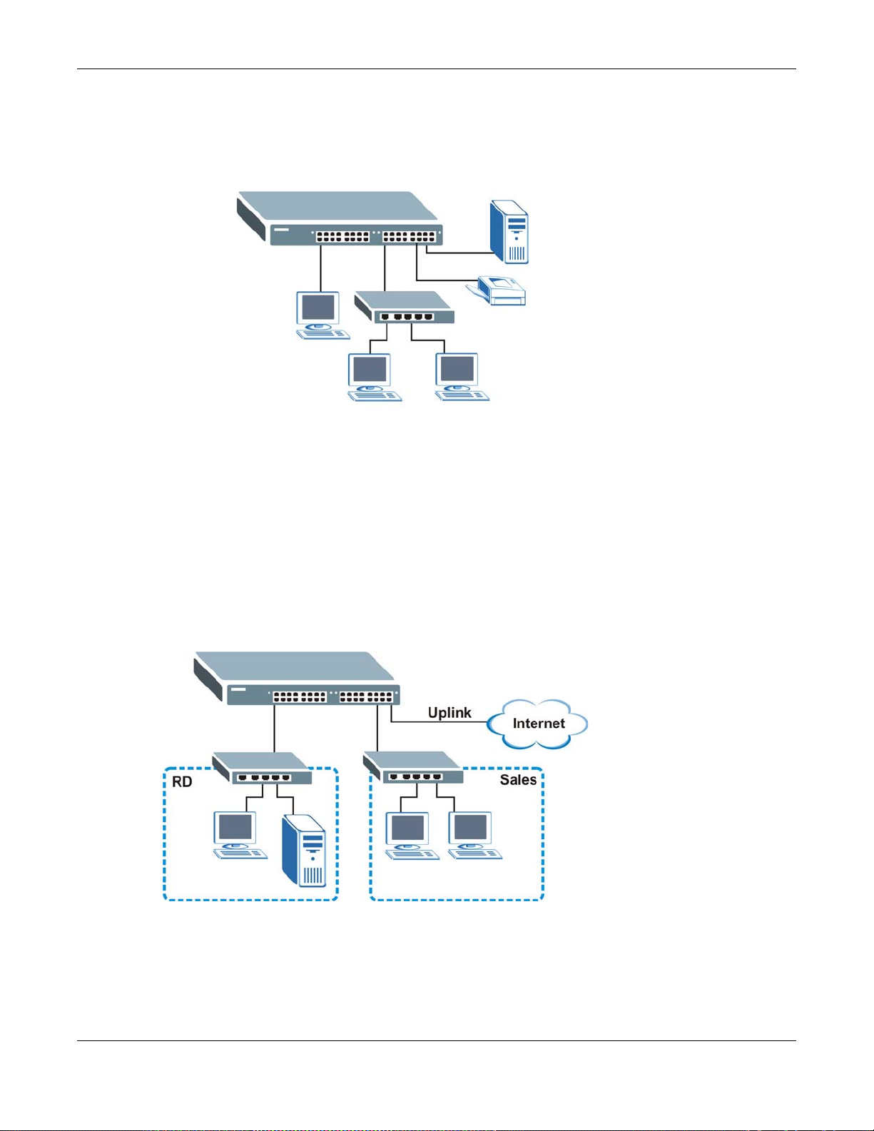
In this example, all computers can share high-speed applications on the server. To expand the
network, simply add more networking devices such as switches, routers, computers, print servers
etc.
Figure 1 Backbone Application
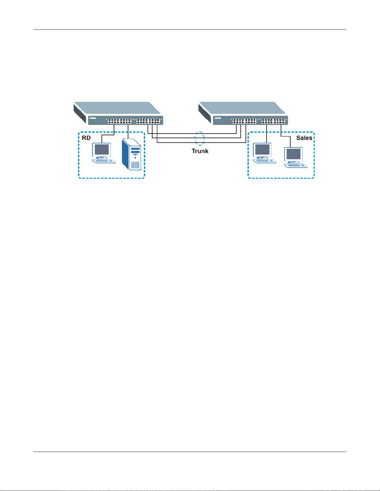
1.1.2 Bridging Example
Chapter 1 Getting to Know Your Switch
In this example, the Switch connects different company departments (RD and Sales) to the
corporate backbone. It can alleviate bandwidth contention and eliminate server and network
bottlenecks. All users that need high bandwidth can connect to high-speed department servers via
the Switch. You can provide a super-fast uplink connection by using a Gigabit Ethernet/mini-GBIC
port on the Switch.
Moreover, the Switch eases supervision and maintenance by allowing network managers to
centralize multiple servers at a single location.
Figure 2 Bridging Application
1.1.3 High Performance Switching Example
The Switch is ideal for connecting two networks that need high bandwidth. In the following
example, use trunking to connect these two networks.
MES3500/MGS3520 Series User’s Guide
18
Chapter 1 Getting to Know Your Switch
Switching to higher-speed LANs such as ATM (Asynchronous Transmission Mode) is not feasible for
most people due to the expense of replacing all existing Ethernet cables and adapter cards,
restructuring your network and complex maintenance. The Switch can provide the same bandwidth
as ATM at much lower cost while still being able to use existing adapters and switches. Moreover,
the current LAN structure can be retained as all ports can freely communicate with each other.
Figure 3 High Performance Switched Workgroup Application
1.1.4 IEEE 802.1Q VLAN Application Examples
A VLAN (Virtual Local Area Network) allows a physical network to be partitioned into multiple logical
networks. Stations on a logical network belong to one group. A station can belong to more than one
group. With VLAN, a station cannot directly talk to or hear from stations that are not in the same
group(s) unless such traffic first goes through a router.
For more information on VLANs, refer to Chapter 9 on page 89.
1.1.4.1 Tag-based VLAN Example
Ports in the same VLAN group share the same frame broadcast domain thus increase network
performance through reduced broadcast traffic. VLAN groups can be modified at any time by
adding, moving or changing ports without any re-cabling.
Shared resources such as a server can be used by all ports in the same VLAN as the server. In the
following figure only ports that need access to the server need to be part of VLAN 1. Ports can
belong to other VLAN groups too.
MES3500/MGS3520 Series User’s Guide
19
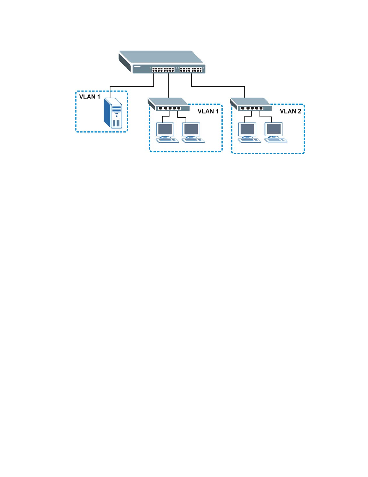
Figure 4 Shared Server Using VLAN Example
1.1.5 IPv6 Support
Chapter 1 Getting to Know Your Switch
IPv6 (Internet Protocol version 6), is designed to enhance IP address size and features. The
increase in IPv6 address size to 128 bits (from the 32-bit IPv4 address) allows up to 3.4 x 10
addresses. At the time of writing, the Switch supports the following features.
• Static address assignment and stateless auto-configuration
• Neighbor Discovery Protocol (a protocol used to discover other IPv6 devices in a network)
• Remote Management using ping SNMP, telnet, HTTP and FTP services
• ICMPv6 to report errors encountered in packet processing and perform diagnostic functions, such
as "ping”
• IPv4/IPv6 dual stack; the Switch can run IPv4 and IPv6 at the same time
• DHCPv6 client and relay
• Multicast Listener Discovery (MLD) snooping and proxy
For more information on IPv6, refer to the CLI Reference Guide.
1.2 Ways to Manage the Switch
Use any of the following methods to manage the Switch.
• Web Configurator. This is recommended for everyday management of the Switch using a
(supported) web browser. See Chapter 4 on page 35.
• Command Line Interface. Line commands offer an alternative to the web configurator and in
some cases are necessary to configure advanced features. See the CLI Reference Guide.
• FTP. Use FTP for firmware upgrades and configuration backup/restore. See Section 37.8 on page
271.
• SNMP. The Switch can be monitored by an SNMP manager. See Section 38.3 on page 274.
• Cluster Management. Cluster Management allows you to manage multiple switches through one
switch, called the cluster manager. See Chapter 41 on page 305.
38
IP
MES3500/MGS3520 Series User’s Guide
20

Chapter 1 Getting to Know Your Switch
1.3 Good Habits for Managing the Switch
Do the following things regularly to make the Switch more secure and to manage the Switch more
effectively.
• Change the password. Use a password that’s not easy to guess and that consists of different
types of characters, such as numbers and letters.
• Write down the password and put it in a safe place.
• Back up the configuration (and make sure you know how to restore it). Restoring an earlier
working configuration may be useful if the device becomes unstable or even crashes. If you
forget your password, you will have to reset the Switch to its factory default settings. If you
backed up an earlier configuration file, you would not have to totally re-configure the Sw itch. Y ou
could simply restore your last configuration.
MES3500/MGS3520 Series User’s Guide
21

Hardware Installation and Connection
This chapter shows you how to install and connect the Switch.
2.1 Installation Scenarios
The Switch can be placed on a desktop or rack-mounted on a standard EIA rack. Use the rubber
feet in a desktop installation and the brackets in a rack-mounted installation.
Note: For proper ventilation, allow at least 4 inches (10 cm) of clearance at the front and
3.4 inches (8 cm) at the back of the Switch. This is especially important for
enclosed rack installations.
CHAPTER 2
2.2 Desktop Installation Procedure
1 Make sure the Switch is clean and dry.
2 Set the Switch on a smooth, level surface strong enough to support the weight of the Switch and
the connected cables. Make sure there is a power outlet nearby.
3 Make sure there is enough clearance around the Switch to allow air circulation and the attachment
of cables and the power cord.
2.3 Mounting the Switch on a Rack
The Switch can be mounted on an EIA standard size, 19-inch rack or in a wiring closet with other
equipment. Follow the steps below to mount your Switch on a standard EIA rack using a rackmounting kit.
2.3.1 Rack-mounted Installation Requirements
• Two mounting brackets.
• Eight M3 flat head screws and a #2 Philips screwdriver.
• Four M5 flat head screws and a #2 Philips screwdriver.
Failure to use the proper screws may damage the unit.
MES3500/MGS3520 Series User’s Guide
22
Chapter 2 Hardware Installation and Connection
2.3.1.1 Precautions
• Make sure the rack will safely support the combined weight of all the equipment it contains.
• Make sure the position of the Switch does not make the rack unstable or top-heavy. Take all
necessary precautions to anchor the rack securely before installing the unit.
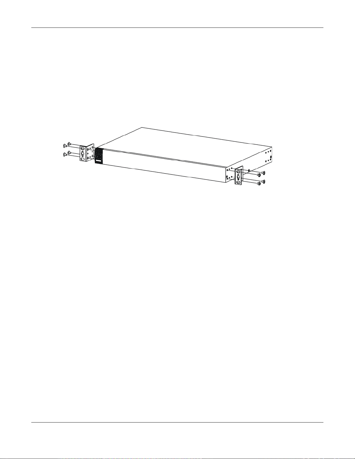
2.3.2 Attaching the Mounting Brackets to the Switch
1 Position a mounting bracket on one side of the Switch, lining up the four screw holes on the br acket
with the screw holes on the side of the Switch.
Figure 5 Attaching the Mounting Brackets
2 Using a #2 Philips screwdriver, install the M3 flat head screws through the mounting bracket holes
into the Switch.
3 Repeat steps 1 and 2 to install the second mounting bracket on the other side of the Switch.
4 You may now mount the Switch on a rack. Proceed to the next section.
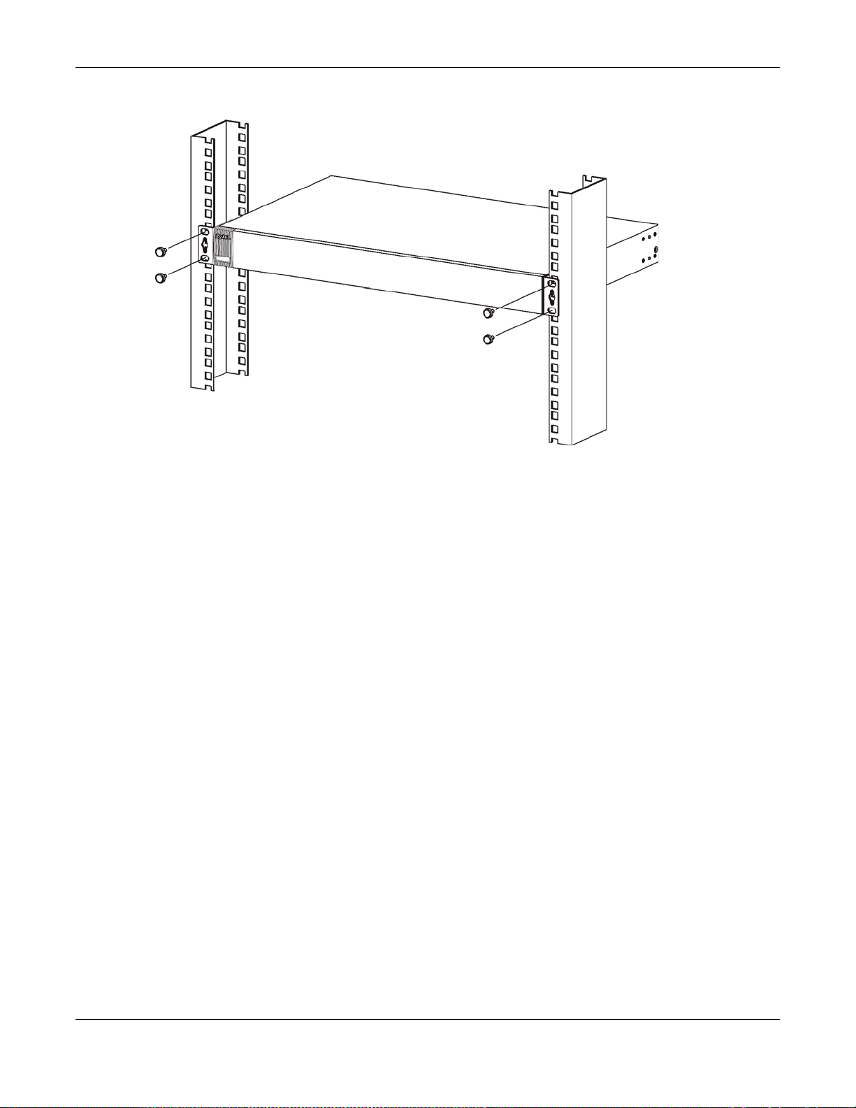
2.3.3 Mounting the Switch on a Rack
1 Position a mounting bracket (that is already attached to the Switch) on one side of the rack, lining
up the two screw holes on the bracket with the screw holes on the side of the rack.
MES3500/MGS3520 Series User’s Guide
23
Chapter 2 Hardware Installation and Connection
Figure 6 Mounting the Switch on a Rack
2 Using a #2 Philips screwdriver, install the M5 flat head screws through the mounting bracket holes
into the rack.
3 Repeat steps 1 and 2 to attach the second mounting bracket on the other side of the rack.
MES3500/MGS3520 Series User’s Guide
24

This chapter describes the front panel and rear panel of the Switch and shows you how to make the
Fast Ethernet Ports
Dual Personality Interfaces
Console Port
LEDs
Power Con nection
Signal slot
Fast Ethernet Ports
Dual Personality Interfaces
Console Port
LEDs
Power Con nection
Power Switch
Signal slot
SFP Slots
Dual Personality Interfaces
Console Port
LEDs
Signal slot
Power Con nection
hardware connections.
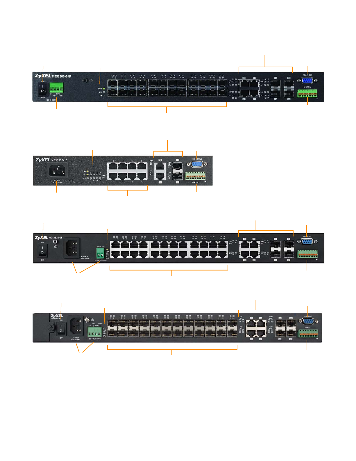
3.1 Front Panel
The following figure shows the front panel of the Switch.
Figure 7 MES3500-24 Front Panel: AC Model
CHAPTER 3
Hardware Overview
Figure 8 MES3500-24 Front Panel: DC Model
Figure 9 MES3500-24F Front Panel: AC Model
MES3500/MGS3520 Series User’s Guide
25
Chapter 3 Hardware Overview
SFP Slots
Dual Personality Interfaces
Console Port
LEDs
Signal slot
Power Connection
Power Switch
Fast Ethernet Ports
Dual Personality Interfaces
Console Port
LEDs
Signal slot
Power Con nection
Gigabit Ethernet Ports
Dual Personality Interfaces
Console Port
LEDs
Power Con nection
Power Switch
Signal slot
SFP Slots
Dual Personality Interfaces
Console Port
LEDs
Power Connection
Power Switch
Signal slot
Figure 10 MES3500-24F Front Panel: DC Model
Figure 11 MES3500-10 Front Panel: AC Model
Figure 12 MGS3520-28 Front Panel: AC/DC Model
Figure 13 MGS3520-28F Front Panel: AC/DC Model
MES3500/MGS3520 Series User’s Guide
26
Chapter 3 Hardware Overview
Gigabit Ethernet Ports
Dual Personality Interfaces
LEDs
Power Switch
SFP slot
Console Port
DC Power Connection
Signal slot
AC Power Connection
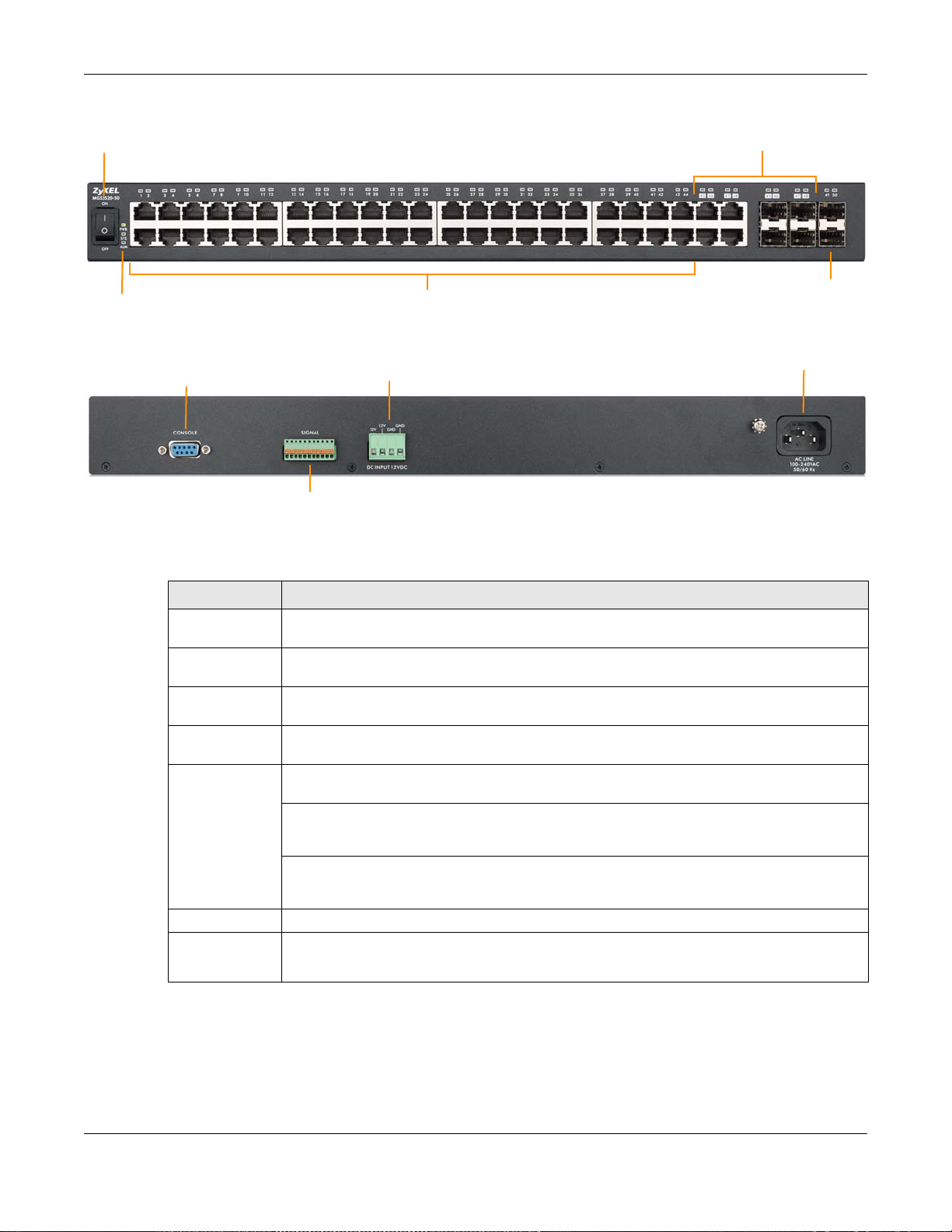
Figure 14 MGS3520-50 Front Panel: AC/DC Model
Figure 15 MGS3520-50 Rear Panel: AC/DC Model
The following table describes the port labels on the front panel.
Table 2 Front Panel Connections
LABEL DESCRIPTION
Power Switch This is for DC model only. After you connect the DC power properly (see Section 3.1.4.2 on
page 31.), put the power switch in the ON position to turn on the Switch.
Power
Connection
RJ-45 Ethernet
Ports
SFP Slots Use transceivers in these slots for fiber-optic or copper connections to a computer, a hub, a
Four or Two
Dual Personality
Interfaces
Console Port The console port is for local configuration of the Switch.
Signal slot Connect the signal input pins to signal output terminals on other pieces of equipment.
Connect an appropriate power supply to this port.
Connect these ports to a computer, a hub, an Ethernet switch or router.
switch or router.
Each interface has one 1000BASE-T RJ-45 port and one transceiver slot, with one port or
transceiver active at a time.
• Four 10/100/1000 Mbps RJ-45 Ports:
Connect these ports to high-bandwidth backbone network Ethernet switches using
1000BASE-T compatible Category 5/5e/6 copper cables.
• Four Transceiver Slots:
Use mini-GBIC or SFP transceivers in these slots for connections to backbone Ethernet
switches.
Connect the signal output pins to a signal input terminal on another piece of equipment.
3.1.1 Console Port
For local management, you can use a computer with terminal emulation software configured to the
following parameters:
MES3500/MGS3520 Series User’s Guide
27

• VT100
• Terminal emulation
• 9600 bps
• No parity, 8 data bits, 1 stop bit
• No flow control
Connect the male 9-pin end of the console cable to the console port of the Switch. Connect the
female end to a serial port (COM1, COM2 or other COM port) of your computer.
3.1.2 Ethernet Ports
The Switch has 24 10/100 Mbps or 24 or 44 10/100/1000 Mbps auto-negotiating, auto-crossover
Ethernet ports. In 10/100 Mbps Fast Ethernet, the speed can be 10 Mbps or 100 Mbps and the
duplex mode can be half duplex or full duplex. In 10/100/1000 Mbps Gigabit Ethernet, the speed
can be 10 Mbps, 100 Mbps or 1000 Mbps and the duplex mode can be half duplex or full duplex.
An auto-negotiating port can detect and adjust to the optimum Ethernet speed (10/100 Mbps or
10/100/1000 Mbps) and duplex mode (full duplex or half duplex) of the connected device.
An auto-crossover (auto-MDI/MDI-X) port automatically works with a str aight -through or crossov er
Ethernet cable.
Chapter 3 Hardware Overview
The Switch has two or four 1000Base-T Ethernet ports, which are paired with a mini-GBIC slot to
create a dual personality interface. The Switch uses up to one connection for each mini-GBIC and
1000Base-T Ethernet pair. The mini-GBIC slots have priority over th e Gigabit ports. This means that
if a mini-GBIC slot and the corresponding GbE port are connected at the same time, the GbE port
will be disabled.
When auto-negotiation is turned on, an Ethernet port negotiates with the peer automatically to
determine the connection speed and d upl ex mod e. If the peer Ethernet port does not support autonegotiation or turns off this feature, the Switch determines the connection speed by detecting the
signal on the cable and using half duplex mode. When the Switch’s auto-negotiation is turned off,
an Ethernet port uses the pre-configured speed and duplex mode when making a connection, thus
requiring you to make sure that the settings of the peer Ethernet port are the same in order to
connect.
3.1.2.1 Default Ethernet Negotiation Settings
The factory default negotiation settings for the Gigabit ports on the Switch are:
• Speed: Auto
•Duplex: Auto
• Flow control: Off
• Link Aggregation: Disabled
3.1.2.2 Auto-crossover
All ports are auto-crossover, that is auto-MDIX ports (Media Dependent Interface Crossover), so
you may use either a straight-through Ethernet cable or crossover Ethernet cable for all Gigabit port
connections. Auto-crossover ports automatically sense whether they need to function as crossover
or straight ports, so crossover cables can connect both computers and switches/hubs.
MES3500/MGS3520 Series User’s Guide
28
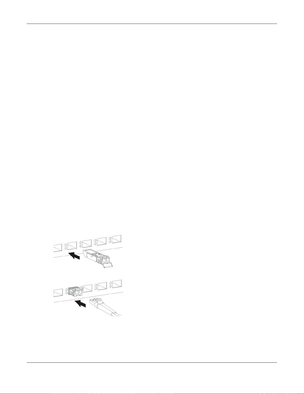
3.1.3 Transceiver Slots
These are slots for mini-GBIC (Gigabit Interface Converter) transceivers or 100 Mbps Small Formfactor Pluggable (SFP) transceivers. A transceiver is a single unit that houses a transmitter and a
receiver. The Switch does not come with transceivers. You must use transceivers that comply with
the SFP Transceiver MultiSource Agreement (MSA). See the SFF committee’s INF-8074i
specification Rev 1.0 for details.
You can change transceivers while the Switch is operating. You can use different transceivers to
connect to Ethernet switches with different types of fiber-optic or even copper cable connectors.
To avoid possible eye injury, do not look into an operating fiber-optic
module’s connectors.
• Type: SFP connection interface
• Connection speed: 1 Gigabit per second (Gbps) or 1 Megabit per second (Mbps)
3.1.3.1 Transceiver Installation
Use the following steps to install a mini-GBIC transceiver (SFP module).
Chapter 3 Hardware Overview
1 Insert the transceiver into the slot with the exposed section of PCB board facing down.
2 Press the transceiver firmly until it clicks into place.
3 The Switch automatically detects the installed transceiver. Check the LEDs to verify that it is
functioning properly.
4 Close the transceiver’s latch (latch styles vary).
5 Connect the fiber optic cables to the transceiver.
Figure 16 Transceiver Installation Example
Figure 17 Connecting the Fiber Optic Cables
3.1.3.2 Transceiver Removal
Use the following steps to remove a mini-GBIC transceiver (SFP module).
1 Remove the fiber optic cables from the transceiver.
MES3500/MGS3520 Series User’s Guide
29
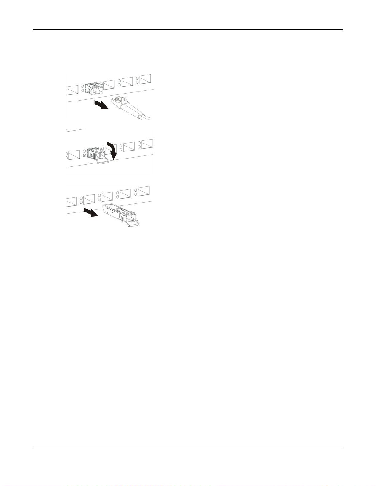
Chapter 3 Hardware Overview
2 Open the transceiver’s latch (latch styles vary).
3 Pull the transceiver out of the slot.
Figure 18 Removing the Fiber Optic Cables
Figure 19 Opening the Transceiver’s Latch Example
Figure 20 Transceiver Removal Example
3.1.4 Power Connector
Make sure you are using the correct power source as shown on the panel and that no objects
obstruct the airflow of the fans.
Use the following procedures to connect the Switch to a power source after you have installed it.
Note: Check the power supply requirements on the panel, and make sure you a re using
an appropriate power source.
Keep the power supply switch and the Switch’s power switch in the OFF
position until you come to the procedure for turning on the power.
Use only power wires of the required diameter for connecting the Switch to a power supply.
3.1.4.1 AC Power Connection
Connect the female end of the power cord to the power socket of your Switch. Connect the other
end of the cord to a power outlet.
MES3500/MGS3520 Series User’s Guide
30
 Loading...