


machine numbers |
A27B43 |
A32B43 |
A36B43 |
Thanks for choosing Zenith!
h o o k u p d i r e c t o r y
p a g e 3
y o u r o n - s c r e e n m e n u s |
20 |
p a g e |
i n d e x
p a g e 50
o p e r a t i n g g u i d e / w a r r a n t y
RECORD YOUR MODEL NUMBER (Now, while you can see it)
The model and serial number of your new TV are located on the back of the TV cabinet. For your future convenience, we suggest that your record these numbers here:
MODEL NO.____________________________________
SERIAL NO.____________________________________
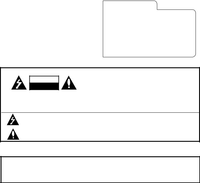
WARNING
RISK OF ELECTRIC SHOCK
DO NOT OPEN
WARNING:
TO REDUCE THE RISK OF ELECTRIC SHOCK DO NOT REMOVE COVER (OR BACK). NO USER SERVICEABLE PARTS INSIDE. REFER SERVICING TO QUALIFIED SERVICE PERSONNEL.
The lightning flash with arrowhead symbol, within an equilateral triangle, is intended to alert the user to the presence of uninsulated “dangerous voltage” within the product’s enclosure that may be of sufficient magnitude to constitute a risk of electric shock to persons.
The exclamation point within an equilateral triangle is intended to alert the user to the presence of important operating and maintenance (servicing) instructions in the literature accompanying the appliance.
WARNING:
TO PREVENT FIRE OR SHOCK HAZARDS, DO NOT EXPOSE THIS PRODUCT TO RAIN OR MOISTURE.
POWER CORD POLARIZATION:
CAUTION: To Prevent Electric Shock, Match wide blade of plug to wide slot, fully insert.
ATTENTION: Pour éviter les chocs électriques, introduire la lame la plus large de la fiche dans la borne correspondante de la prise et pousser jusqu’au fond.
NOTE TO CABLE/TV INSTALLER:
This reminder is provided to call the cable TV system installer’s attention to Article 820-40 of the National Electric Code (U.S.A.). The code provides guidelines for proper grounding and, in particular, specifies that the cable ground shall be connected to the grounding system of the building, as close to the point of the cable entry as practical.
REGULATORY INFORMATION:
This equipment has been tested and found to comply with the limits for a Class B digital device, pursuant to Part 15 of the FCC Rules. These limits are designed to provide reasonable protection against harmful interference when the equipment is operated in a residential installation. This equipment generates, uses and can radiate radio frequency
energy and, if not installed and used in accordance with the instruction manual, may cause harmful interference to radio communications. However, there is no guarantee that interference will not occur in a particular installation. If this equipment does cause harmful interference to radio or television reception, which can be determined by turning
the equipment off and on, the user is encouraged to try to correct the interference by one or more of the following measures: • Reorient or relocate the receiving antenna.
•Increase the separation between the equipment and receiver.
•Connect the equipment into an outlet on a circuit different from that to which the receiver is connected.
•Consult the dealer or an experienced radio/TV technician for help.
CAUTION:
Do not attempt to modify this product in any way without written authorization from Zenith Electronics Corporation. Unauthorized modification could void the user’s authority to operate this product.
INSTALLATION |
GETTING STARTED |
P A G E 3 |
|
|
|
Hook-Up Directory
IMPORTANT!! Use this page to decide where you need to begin your setup.
First, find the line below that best describes what you want to do, then go to that page number.
Note: Design and Specifications are subject ot change without prior notice.
INPUT HOOK-UP OPTIONS
Antenna |
If you receive your TV channels from an antenna, go to . . . . . . . . . . . . . . . . . . . . . . . . |
page 6 |
Cable |
If you are receiving cable directly from the wall or use a cable box, go to . . . . . . . . . . . . |
page 7 |
Antenna/VCR
VCR and Cable
Super VHS
If you receive your TV channels froma an antenna and have a VCR, go to . . . . . . . . . . . . |
page 8 |
If you want to connect a VCR and have cable service or a cable box, go to . . . . . . . . . . . page 9
If you are using a Super-VHS VCR, go to . . . . . . . . . . . . . . . . . . . . . . . . . . . . . . . . . page 10
For general information about the jacks on your Entertainment
Machine, see pages 4 and 5.
This page will help you hook up your Entertainment Machine properly.
AUDIO EQUIPMENT OPTIONS
External Stereo |
To hook up your entertainment machine to an external stereo, go to . . . . . . . . . . . . . . |
page 11 |
3376-O
P A G E 4 |
INSTALLATION |
GETTING STARTED |
|
|
|
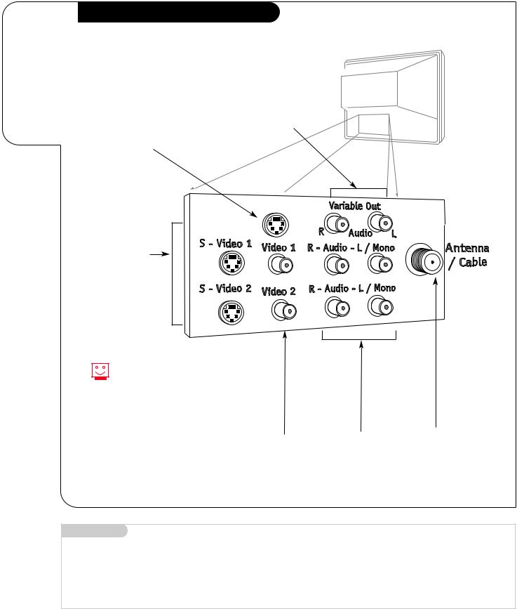
Connection Jacks
Your jack-pack and its various uses.
Variable Audio Out
Used to connect a stereo system.
Data Port
Reserved for future use.
Data Port
S-Video 1
S-Video 2
A feature available with some very high-end equipment that provides even better picture quality.
Using the Audio/Video jacks provides the best picture and sound.
Video 1
Video 2
Connects the video signals from any piece of equipment.
Right/Left Audio
Used for stereo sound from various types of equipment.
RF Connector
Antenna/Cable
Used to connect an antenna or cable service to the television, either directly or through a cable box.
Mini glossary
JACK |
A connection on the back of a TV, VCR, or any other A/V device. This includes the RF jack (Antenna/Cable) that is threaded with a place |
|
for a small wire in the center, and the Audio/Video jacks that have a bigger opening and are color-coded. |
SIGNAL |
Picture and sound traveling through cable, or on the air, to your television screen. |
3376-O
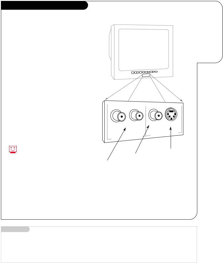
Front A/V Jacks
Note: Not available on Model No. A27B43
There are four jacks on the front of your Entertainment Machine that make
connecting Audio/Video devices like video games and camcorders very simple.
The jacks are located behind a small door below the buttons on the front panel.
The jacks are exactly like those found on the jack pack on the back of your Entertainment Machine. Which means
that any equipment that connects to those types of jacks in the jack pack, can also be connected in front.
To use the front jacks as the signal source, use the Source menu as described on page 21. The jacks are labeled ”Front Video,” and “Front S-Video.”
You can connect equipment to either the Front Video jack or Front S-Video jack, but not both at the same time.
INSTALLATION |
GETTING STARTED |
P A G E 5 |
|
|
|
Hooking
up temporary equipment to your
Entertainment Machine.
Typical
Front Audio/Video
Input Jacks Panel
LEFT |
|
RIGHT |
VIDEO |
S-VIDEO |
|
|
|
|
|
||
|
|
|
|
|
|
|
|
|
FRONT |
VIDEO |
INPUT |
|
|
INPUT |
|
||
|
AUDIO |
|
|
||
FRONT |
|
|
|
||
|
|
|
|
||
|
|
|
|
|
|
Left/Right Audio
Used for stereo sound from various types of equipment.
Video
Connects the video signals from any piece of equipment.
S-Video
A connection availale for some very high-end equipment that provides even better picture quality.
Mini glossary
A/V CABLES |
Audio/Video cables. Three cables bunched together—Right audio (red), Left audio (white), and Video (yellow). A/V cables are used |
|
for stereo playback of videocassettes and for higher quality picture and sound from other A/V devices. |
A/V DEVICE |
Any device that produces video or sound (VCR, DVD, cable box, or television). |
3376-O
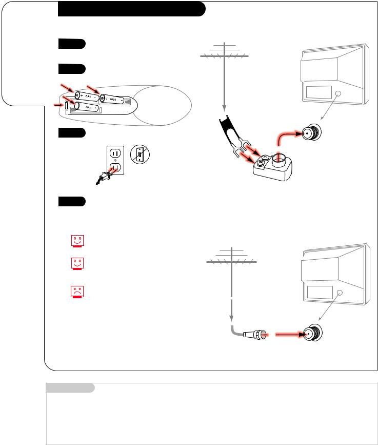
P A G E 6 |
INSTALLATION |
STANDARD |
|
|
|
Connect an
antenna
to your
Entertainment
Machine.
Hook Up Your Antenna to the TV
1 |
See diagrams at right to hook up |
|
your Entertainment Machine. |
2 |
Remove the back of the remote |
and put in three AAA batteries. |
|
back of remote |
3 |
Plug in your TV. Do not plug it |
|
into a switched outlet. |
120V
60Hz
Flat-Wire Antenna to Adapter |
|
|
Antenna |
TV back |
|
|
||
Flat wire |
TV back panel |
|
(300 ohm) |
||
(expanded view) |
||
|
||
|
Antenna |
|
|
/ Cable |
300/75 ohm Adapter
4 |
Go to page 13 to Auto Program |
Round Antenna Wire |
|
your Entertainment Machine. |
|||
|
|
If you have a 75 ohm RF cable, then you don’t need any adapters!
Remember, when screwing RF cables onto jacks, clockwise tightens, and counterclockwise loosens.
A 300 to 75 ohm adapter is not included with your Zenith Entertainment Machine.
TV back
Antenna
TV back panel
(expanded view)
RF coaxial wire (75ohm)
Antenna
/ Cable
Mini glossary
75 OHM RF CABLE |
The wire that comes from an off-air antenna or cable service provider. Each end looks like a hex shaped nut with a wire |
|
sticking through the middle, and it screws onto the threaded Antenna/Cable jack on the back of your TV. |
300 TO 75 OHM ADAPTER |
A small device that connects a two-wire 300 ohm antenna to a 75 ohm RF jack. They are usually about an |
|
inch long with two screws on one end and a round opening with a wire sticking out on the other end. |
3376-O
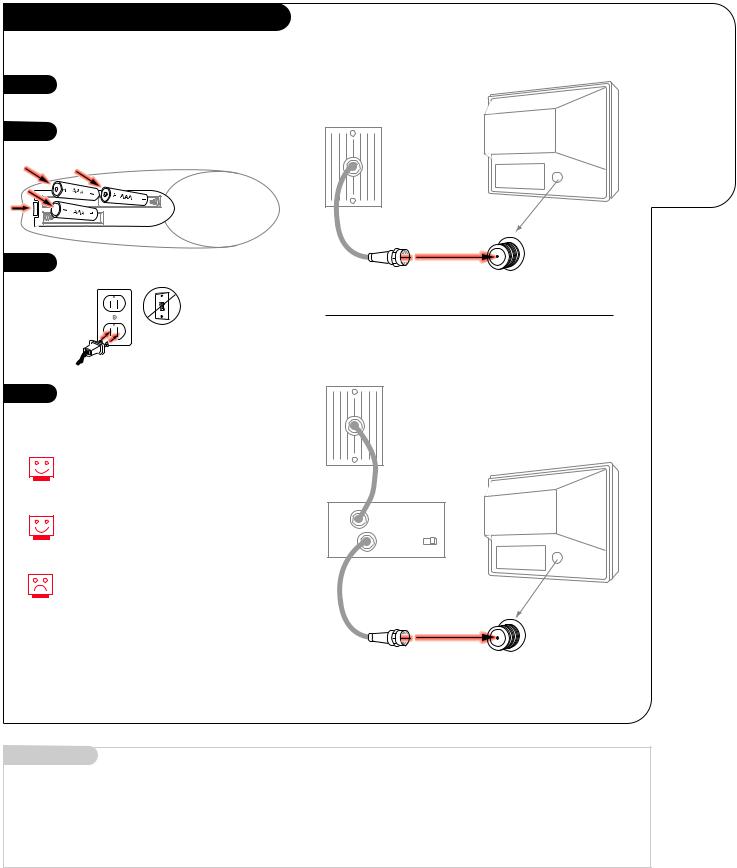
Hook Up Your Cable (CATV) to the TV
1 |
See diagrams at right to hook up |
|
your Entertainment Machine. |
2 |
Remove the back of the remote |
|
and put in three AAA batteries. |
||
|
back of remote
3 |
Plug in your TV. Do not plug it |
|
into a switched outlet. |
||
|
120V
60Hz
4 |
Go to page 13 to Auto Program |
|
your Entertainment Machine. |
||
|
If you’re using a cable box, leave your TV on channel 3 or 4 and use your cable box to change channels.
Remember, when screwing RF cables onto jacks, clockwise tightens, and counterclockwise loosens.
If you’re using a cable box, AutoProgram (page 13) might only find the channel your cable service is on (usually channel 3 or 4). Don’t worry, that’s all you need!
INSTALLATION |
STANDARD |
P A G E 7 |
|
|
|
Connect cable to your
Without Cable Box Entertainment Machine.
Cable TV wall jack
TV back
TV back panel (expanded view)
RF coaxial wire (75ohm)
Antenna
/ Cable
With Cable Box
Cable TV wall jack
In |
|
TV back |
Cable box |
||
Out |
output |
3 4 |
|
switch |
|
TV back panel
(expanded view)
RF coaxial wire (75ohm)
Antenna
/ Cable
Mini glossary
CABLE SERVICE The wire that supplies all your cable TV (CATV) stations.
3376-O

P A G E 8 |
INSTALLATION |
STANDARD |
|
|
|
Connect your off-air antenna and VCR to your Entertainment Machine.
Hook Up Antenna and VCR to the TV
1 |
See diagrams at right to hook up |
|
your Entertainment Machine. |
2 |
Remove the back of the remote |
|
and put in three AAA batteries. |
||
|
Flat-Wire Antenna to Adapter and Audio/Video Cables
Antenna |
Flat wire |
|
VCR back |
|
(300 ohm) |
|
|
|
|
VCR back AV panel |
||
300/75 ohm |
In |
output |
3 4 |
Adapter |
|
switch |
|
|
Audio |
Video |
|
|
Out |
||
|
R-L Out |
Out |
|
3
4
back of remote
Plug in your TV. Do not plug it into a switched outlet.
120V
60Hz
Go to page 13 to Auto Program your Entertainment Machine.
TV back
RF coaxial wire (75ohm)
not included with TV
A/V cables not included with TV
TV back panel (expanded view)
Remember, when screwing
RF cables onto jacks, clockwise tightens, and counterclockwise loosens.
Use Video sources for better picture and sound.
No A/V cables are included with your Zenith Entertainment Machine.
Without A/V cables, VCRs will not play videocassettes in stereo sound.
Round Cable to VCR and Audio/Video Cables |
|
|
|
|
VCR back |
|
|
Antenna |
|
|
|
VCR back AV panel |
|||
Round wire (75ohm) |
output |
|
|
In |
|
||
|
switch 3 4 |
||
Out |
Audio |
Video |
|
R-L Out |
Out |
||
|
|||
TV back |
|
|
|
RF coaxial wire |
|
|
|
(75ohm) |
|
|
|
not included |
|
|
|
with TV |
|
|
|
A/V cables not included with TV
TV back panel (expanded view)
3376-O
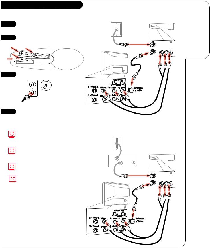
Hook Up Your Cable (CATV) and VCR
1 |
See diagrams at right to hook up |
|
your Entertainment Machine. |
2 |
Remove the back of the remote |
|
and put in three AAA batteries. |
||
|
back of remote
3 |
Plug in your TV. Do not plug it |
|
into a switched outlet. |
||
|
120V
60Hz
4 |
Go to page 13 to Auto Program |
|
your Entertainment Machine. |
||
|
Leave your VCR and your television tuned to channel three and use the cable box to change channels.
Remember, when screwing in RF cables onto jacks, clockwise tightens, and counterclockwise loosens.
Use Video sources for better picture and sound.
No A/V cables are included with your Zenith Entertainment Machine. Without A/V cables, VCRs will not play videocassettes in stereo sound.
INSTALLATION |
STANDARD |
P A G E 9 |
|
|
|
Cable Service and Audio/Video Cables
|
|
Connect |
|
|
your VCR and |
Cable TV |
|
Cable to your |
wall jack |
|
Entertainment |
|
|
|
|
VCR back |
Machine. |
VCR back AV panel |
||
Round wire (75ohm) |
output |
|
In |
|
|
|
switch 3 4 |
|
Out |
Audio |
Video |
R-L Out |
Out |
|
TV back |
|
|
RF coaxial wire |
|
|
(75ohm) |
|
|
not included |
|
|
with TV |
|
|
A/V cables not included with TV
TV back panel (expanded view)
Cable Service with a Cable Box and Audio/Video Cables
Cable TV wall jack
In |
Cable box |
VCR back |
|
|
|
||
Out |
output |
|
|
switch 3 4 |
|
|
|
|
|
|
|
|
VCR back AV panel |
||
|
Round wire (75ohm) |
output |
|
|
In |
|
|
|
|
switch 3 4 |
|
|
Out |
Audio |
Video |
|
R-L Out |
Out |
|
|
TV back |
|
|
|
RF coaxial wire |
|
|
|
(75ohm) |
|
|
|
not included |
|
|
|
with TV |
|
|
A/V cables not included with TV
TV back panel (expanded view)
3376-O
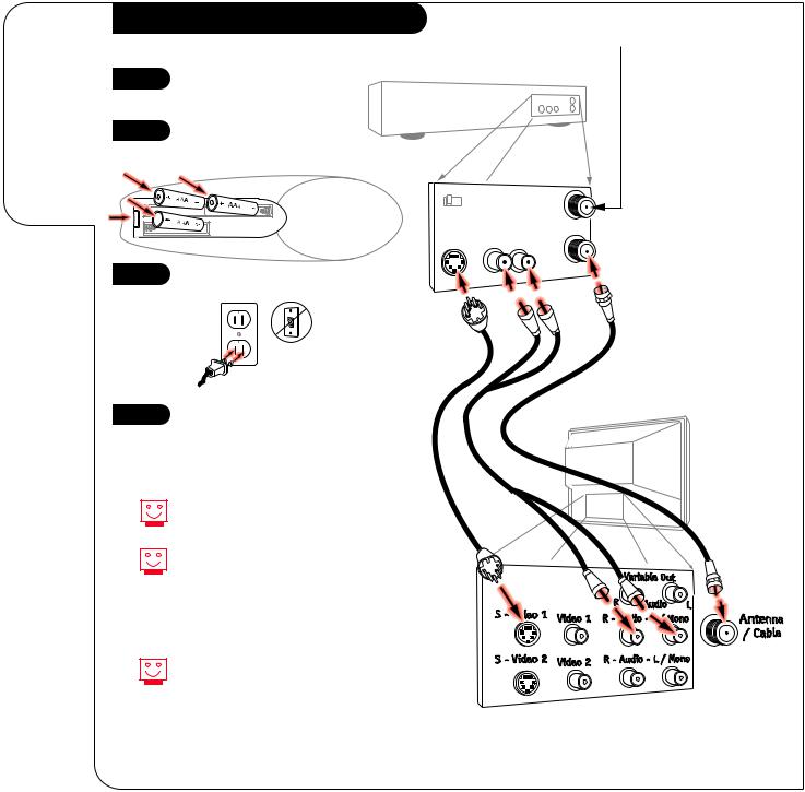
P A G E 1 0 |
INSTALLATION |
STANDARD |
|
|
|
Super VHS VCR
Connecting a
Super VHS VCR
to your
Entertainment
Machine.
1
2
See diagrams at right to hook up your Entertainment Machine.
Remove the back of the remote and put in three AAA batteries.
back of remote
3 |
Plug in your TV. Do not plug it |
|
into a switched outlet. |
||
|
120V
60Hz
4 |
Go to page 13 to Auto Program |
|
|
|
your Entertainment Machine. |
Use S-Video or Video sources for better picture and sound.
To use with PIP: go to the Source Menu (page 21) and choose the jack you’ve connected your S-VHS VCR to (S-VHS 1, or S-VHS 2) as the Main or PIP source.
S-Video 1 and S-Video 2 are input connectors.
Super VHS VCR Connections and Audio/Video Cables
Attach to cable wall jack, cable box, or
antenna
Super VHS VCR
|
|
Back AV panel |
||
|
|
|
In |
|
3 |
4 |
|
Ant |
|
S-Video |
Audio |
|||
|
||||
Out |
R-L Out |
Out |
||
Cables
not included with TV
TV back
3374-O |
3376-O |
Variable Audio Out Hook-ups
Before you begin plugging in your stereo system, it’s a good idea to put it in its approximate place first. That way you know how much audio cable you have or will need.
1 |
Locate the jacks marked Audio |
|
Variable Out. These are for the |
||
|
||
|
stereo system. Connect the |
|
|
stereo system’s cables, accord- |
|
|
ing to their color (red is the |
|
|
right channel, white the left) |
|
|
to these jacks. |
INSTALLATION |
STEREO SYSTEM |
P A G E 1 1 |
|
|
|
Variable Audio Out to Stereo System using Right/Left Audio Cables
Get the best sound possible from your
Entertainment Machine.
TV back
Audio cables not included with TV
These cables should be included with your stereo system.
R-L Audio
Input
Stereo
System
Mini glossary
AUDIO CABLES |
Two cables bunched together—Right audio (red), and Left audio (white). Audio cables are used for stereo play |
|
back of videocassettes and for higher quality sound from other A/V devices. |
3376-O
P A G E 1 2 |
OPERATION |
TRACKBALL MENU OPERATION |
|
|
|
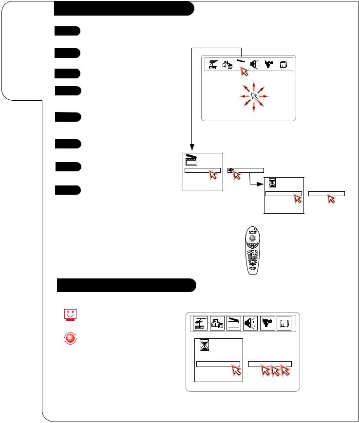
Using the Z-Trak to operate the on-screen menus.
MBR Z-Trak TV Menu Operation
1 |
Press MODE repeatedly until the |
|
|
||||||||||||||||||||||||||
|
TV indicator lights. |
|
|
||||||||||||||||||||||||||
2 |
Point Z-Trak at Entertainment |
|
|
||||||||||||||||||||||||||
3 |
Machine. |
|
|
|
|
|
|
|
|
|
|
|
|
|
|
|
|
|
|
|
|
|
|
|
|
|
|
|
|
|
|
|
|
|
|
|
|
|
|
|
|
|
|
|
|
|
|
|
|
|
|
|
|
|
|
|
|
|
|
Press POWER to turn TV on. |
|
|
|||||||||||||||||||||||||||
4 |
Press trackball down and release, |
|
|
||||||||||||||||||||||||||
to place selector arrow on TV |
|
|
|||||||||||||||||||||||||||
|
|
|
|||||||||||||||||||||||||||
|
screen. |
|
|
||||||||||||||||||||||||||
5 |
Rotate trackball to move selector |
|
|
||||||||||||||||||||||||||
|
arrow around screen until menu |
|
|
||||||||||||||||||||||||||
selection icons appear.
6 Move the selector arrow over the menu option.
|
|
Special |
|
7 |
Press trackball down and release |
123 Features |
|
Tim erSetup |
SetTim ers |
||
|
to select option etc. |
C h Labels |
|
|
|
Source ID |
|
Timer |
|
|
|
ParentalC tl |
|
|
|
8 |
When finished, move selector |
Auto D em o |
|
Menu |
|
|
|
|
|||
arrow off any menu and press |
|
|
Sleep Tim er |
: |
|
|
|
|
O n Tim e |
|
|
|
trackball down and release to |
|
|
|
|
|
|
|
O ffTim e |
|
|
|
remove menus from view. |
|
|
O n/O ffTim er |
|
|
|
|
|
|
|
|
|
|
|
power |
|
|
|
|
|
aux 1 aux 2 |
|
|
|
|
mode |
|
|
|
|
mute |
surf |
|
|
|
|
vol |
|
|
|
|
|
ume |
|
|
|
|
|
1 |
2 |
3 |
|
|
|
4 |
5 |
6 |
|
|
|
7 |
8 |
9 |
|
|
|
source |
0 |
enter |
|
|
|
menu |
|
quit/ |
|
|
|
|
|
pause |
|
stop
rew
play
Setting Clock/Timer using Trackball
As shown to the right, when setting the clock or on the timer menu: point on hours and click to set, point on minutes and click to set, point on AM or PM and click to change.
123 |
Timer |
|
Menu |
|
Sleep Tim er |
|
O n Tim e |
12 : 30 AM |
O ffTim e |
|
O n/O ffTim er |
|
3376-O
Auto Program (Channel Search)
1 |
|
Press MENU repeatedly until the |
||
|
|
|
|
Setup Menu appears. |
2 |
|
Use the UP/DOWN arrow keys, to |
||
|
|
|
|
select Auto Program. |
3 |
|
Press a LEFT/RIGHT arrow. |
||
4 |
|
Use the UP/DOWN arrow keys, to |
||
|
|
|
|
select Off Air Antenna, or if you |
|
|
|
|
subscribe to cable service, select |
|
|
|
|
Cable. |
|
|
|
|
Note: The flashing option is the |
|
|
|
|
one selected. |
5 |
|
Press a LEFT/RIGHT arrow to |
||
|
|
|
|
begin the channel search. |
6 |
|
After channel search is done, use |
||
|
|
|
|
Channel UP/DOWN or number key- |
|
|
|
|
pad to select channels. |
|
|
|
|
When the screen tells you how |
|
|
|
|
many channels it found, click |
|
|
|
|
the Trakball for TV viewing. |
|
|
|
|
To customize your channel selec- |
|
|
|
|
|
|
|
|
|
tion, see Channel Add/Del/Surf on |
|
|
|
|
|
|
|
|
|
page 22. |
1 
3/5
INSTALLATION |
CHANNEL SEARCH |
P A G E 1 3 |
|
|
|
Automatically finds available channels in your area.
|
cable |
power |
|
|
vcr |
aux 1 |
aux |
2 |
|
tv |
|
|
||
|
|
|
||
mode
v |
mute |
surf |
flshbk |
|
|
e |
l |
o |
|
|
|
|
|||
l |
|
|
|
|
n |
|
|
u |
|
|
|
|
|
|
|
m |
|
|
n |
|
|
||
|
h |
|
|
|
|||
|
e |
|
c |
a |
|
|
|
|
|
|
|
|
|
||
1 |
2 |
3 |
4 |
5 |
6 |
|
|
|
7 |
|
9 |
source |
0 |
enter |
menu |
pip |
quit/ |
|
||
|
|
|
record |
|
pause |
2/4
|
play |
rew |
f. fwd |
|
stop |
3376-O
P A G E 1 4 |
REMOTE OPERATION |
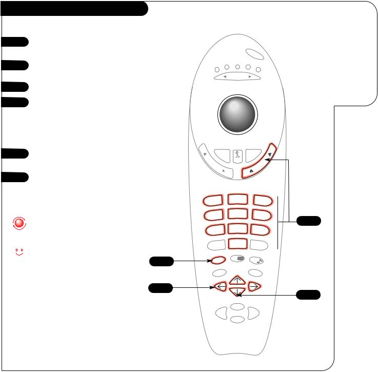
MBR Z-TRAK KEY FUNCTIONS IN TV MODE |
|
|
|
All the keys on your remote, and what
they do in TV mode.
TV Mode Functions
MODE INDICATOR LIGHTS
Illuminate to show which mode your remote is in.
MODE LEFT/RIGHT
Adjust which mode your remote is working in.
MUTE
Press once for Soft Mute, and again for full Mute.
tv
vcr
cable
mode
power |
|
aux 1 |
aux |
|
|
|
2 |
POWER
Turn your Entertainment Machine and all other programmed equipment on or off.
TRAKBALL
Clicking and rolling activates and moves the on-screen selector arrow (pointer). See page 12 for on-screen menu operation. See page 38 for programming remote.
SURF
Use the regular channel selection or your customized channel Surf list.
VOLUME LEFT/RIGHT
Increase/decrease the sound level
SOURCE
Push to switch between available sources connected to your Entertainment Machine.
mute
v o l ume
1 4 7
source
surf |
flshbk |
|
|
|
|
l |
|
|
|
|
|
e |
|
|
|
|
|
n |
|
|
|
|
|
n |
|
|
|
|
|
a |
|
|
|
|
|
h |
|
|
|
|
|
|
c |
|
|
|
|
|
2 |
3 |
5 |
6 |
8 |
9 |
0 |
enter |
FLSHBK (FLASHBACK)
Return immediately to the last channel viewed.
CHANNEL UP/DOWN
Scroll through your available channels.
 NUMBER KEYPAD
For direct channel selection and programming functions.
ENTER
Push to accept menu choices or after channel numbers for faster transfer.
MENU |
menu |
|
Displays on-screen menus. |
||
|
||
RECORD, PAUSE |
record |
|
Control the functions on your VCR. |
|
|
ARROW KEYS |
|
|
Use to select and adjust |
|
|
on-screen menu choices. |
|
|
|
rew |
Note: You can still control your VCR in TV mode.
pip |
quit/ |
PIP SNAPSHOT |
|
1st push, freezes main picture in PIP inset. |
|
|
|
|
|
pause |
2nd push, begins normal PIP operation. |
|
3rd push, removes PIP inset. |
|
|
|
|
QUIT |
|
Leaves programming menus and |
|
clears screen of displays. Swaps PIP and |
play |
Main audio sources with PIP on. |
|
f. fwd |
stop |
REW, FFWD, PLAY, STOP |
|
Control the functions on your VCR. |
TRK 4000
124-219-01 221-1282
Mini glossary
MODE |
The device that the remote control is currently controlling; TV, VCR, Cable Box, Aux 1, or Aux 2. |
3376-O
Front Panel
1 |
To access the menus, press MENU |
|
on the panel. Cycle through the |
||
|
||
|
various menus by pressing MENU |
|
|
repeatedly. |
|
2 |
Press SELECT repeatedly to high- |
|
|
||
|
light and select the option you |
|
|
want to modify. |
|
3 |
Press either Right or Left on the |
|
ADJUST key to modify the option |
|
you have chosen. |
|
4 |
Press ENTER to return to normal |
|
TV viewing. |
||
|
Refer to the various menu pages on how to use the on-screen menus.
The CHANNEL and
work just as they do on your remote control.
Lost the remote? Call Zenith at 1-800-365-1690 to ask about purchasing a new one.
OPERATION |
TV FUNDAMENTALS |
P A G E 1 5 |
|
|
|
Using the ten-button front panel to operate the menus.
ENTER |
ADJUST |
SELECT MENU |
VOLUME |
CHANNEL |
OFF-ON |
3 1
4 2
3376-O
P A G E 1 6 |
REMOTE OPERATION |
MBR Z-TRAK TRACKBALL REMOTE |
|
|
|
Learn the easiest way to get at every option on your Entertainment Machine!
Using Your Trakball Remote
1 |
Make sure your Entertainment |
|
Machine is on. |
||
|
||
2 |
Just click the Trakball by |
|
pressing gently with your |
||
|
||
|
thumb, and an arrow-shaped |
|
|
pointer will appear on-screen. |
|
3 |
You can now move the pointer |
|
anywhere on the screen by |
||
|
rolling the Trakball with your |
|
|
thumb. As you move it from |
|
|
side to side, top to bottom, |
|
|
different menus will instantly |
|
|
appear. |
|
4 |
You can use and adjust any of |
|
these options by rolling the |
|
pointer so the index finger is |
|
|
touching the icon for the |
|
|
menu or option you want. |
|
5 |
Click the Trakball again, |
|
and the option or menu is |
||
|
||
|
selected. |
|
6 |
When you’re finished, either |
|
wait a few seconds and the |
||
|
||
|
pointer will disappear, or |
|
|
move the pointer so that it |
|
|
isn’t touching any icons or |
|
|
menus, and click again. |
The point-and-click interface does everything buttons do, just like your computer mouse. Click words on-screen instead of pressing the button. Or click on items instead of scrolling with the arrow keys.
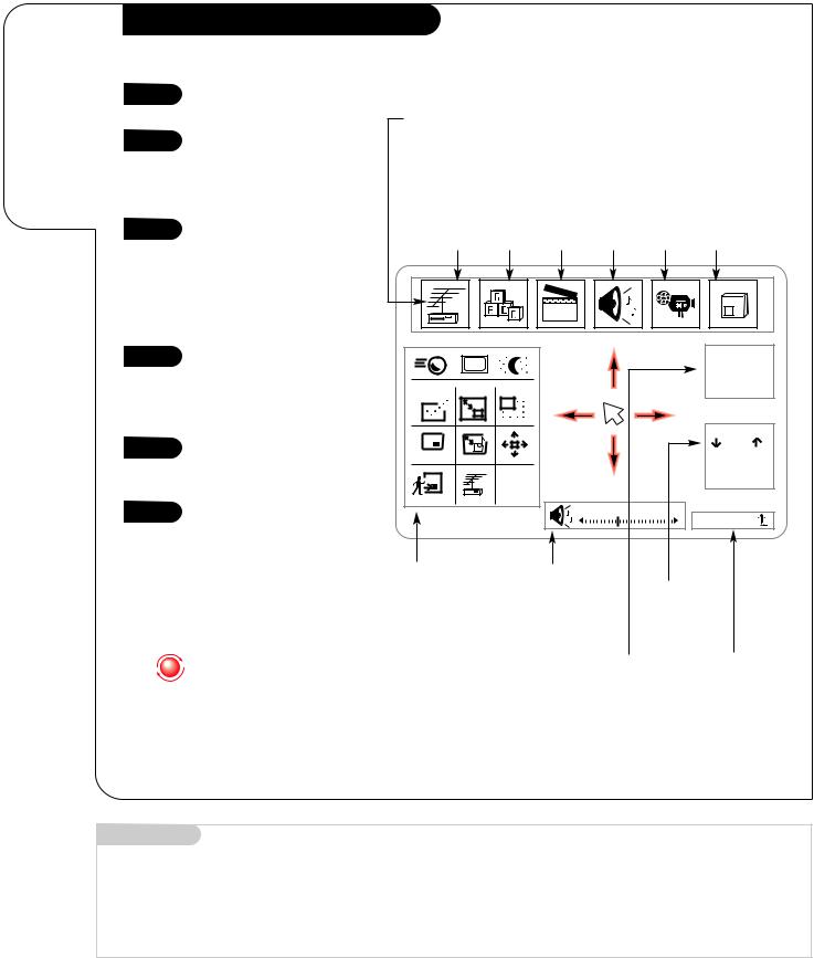
Typical Icons Menu Selection Bar, which lets you access the Source menu (see page 21), the Setup menu (see pages 13, 22-26), the Special Features menu (see pages 27-31), the Audio menu (see page 32), the Video menu (see page 33), and the Picture-in-picture menu (see page 34).
|
|
Special |
Audio |
Video |
|
Source |
Setup |
Features |
PIP |
||
Menu |
Menu |
Menu |
Menu |
Menu |
Menu |
|
|
123 |
|
|
|
CC |
|
|
|
|
Ch 07-NBC |
|
|
|
|
4:55 |
|
|
|
|
|
|
|
|
|
|
|
|
Mono |
PIP |
|
|
|
|
|
|
|
|
|
|
Ch |
FREEZ |
|
|
|
|
All Chan |
|
PIP |
|
|
|
Flashback |
|
|
|
|
|
|
|
CHANGE |
|
|
|
|
|
|
|
Volume |
|
|
|
|
|
|
|
Surf |
Z-Trak |
|
Volume |
|
Channel |
|
Picture-in- |
|
Display |
|
Selection |
|
Picture Menu |
|
Click any- |
Display |
||
(see page 37). |
|
where on |
Click to |
||
|
|
bar to |
|
change |
|
|
|
adjust |
|
Channel/Time |
Surfing |
|
|
sound |
|
||
|
|
|
Display |
Display |
|
|
|
|
|
||
Mini glossary
POINTER |
The image of the selector arrow that appears on-screen and points to the option you want to work with. |
ICON |
A small picture on your screen that represents a function or menu item. |
3376-O
OPERATION TV FUNDAMENTALS P A G E 1 7
Basic Television Operation
Source
Pressing the Source key on the remote switches between the Video inputs and Cable/Antenna input. The Time/Channel display will read “Video” in place of a channel number if A/V inputs are selected as the picture source.
Cable/Antenna Input: This setting allows you to change cable or antenna channels and to view videocassettes on channel 3 (or 4) in mono sound.
Video Input: This setting allows stereo playback of videocassettes. The television cannot change channels in the Video mode, but the VCR can.
Introducing you to the basics of your Entertainment Machine
Channel/Label or Video (Indicates Source) Time
Audio Mode
PIP Channel & Label
(Musical Note Shows Source of sound)
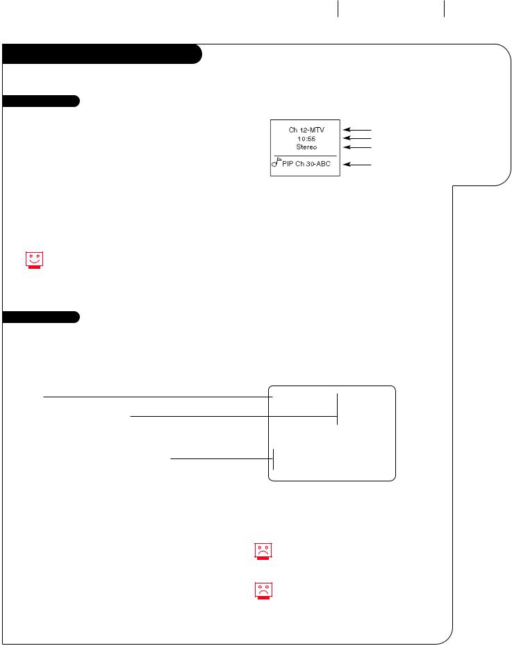
To view the current input source, press ENTER on your remote. The Time/Channel display should appear in the upper-right hand corner of the screen. If the display reads ‘Video,’ then the source is an A/V input. If the display reads a channel number, then the source is Cable/Antenna.
XDS Data Feature
XDS = Extended Data Service
Some public broadcasting stations are including on the signal they provide additional information (data) about the program. This data (see example) appears on your TV screen when you press ENTER; if the broadcaster is adding XDS data.
Date
Channel/Time/Audio Display
(shown with PIP display, if PIP is on)
Title of Program
Length of Program (in hours and minutes)
Time Remaining (in hours and minutes)
Jan/30/98 |
|
Ch 25-MTV |
||
7:55 |
|
|||
|
|
|
||
|
|
|
Stereo |
|
|
|
|
|
|
|
|
PIP Ch 30-ABC |
||
|
|
NOVA |
||
|
|
|
|
|
Length 00:44 |
Time Left 00:37 |
|||
Showing XDS Data
Select a channel. Press ENTER to display XDS data; if available.
XDS Channel Labels
XDS can provide a channel label automatically. For the programs to display an XDS channel label, select the dashes
(- - - -) for that channel from the Channel Labels option in the Special Features Menu.
Example of an XDS Data Display
At this printing, XDS data is only being provided by some public broadcasting stations; and as a result, it is only available on some channels.
You must set the Clock in the Setup Menu before the time will appear on the Channel/Time Display or on the XDS display.
3376-O
 Loading...