

Page 1

Machine Controller MP2300S
Basic Module
USER'S MANUAL
Model: JEPMC-MP2300S-E
MP2300S
YAS KAWA
BATTERY
M-
I/II
RDY
RUN
ALM
ERR
MTX
BAT
TRX
IP
STOP
SUP
INT
SW
CNFG
1
MON
TEST
NO
E-INT
E-TEST
ON
SW
2
NO
ON
Specifications and Functions
Overview
Mounting and Wiring
RLY
OUT
Ethernet
LINK
DC
24V
DC
0V
100M
Outline of Motion Control Systems
System Start Up and
Easy Programming
Built-in Ethernet Communications
Slave CPU Synchronous Function
Maintenance and Inspection
Troubleshooting
1
2
3
4
5
6
7
8
9
MANUAL NO. SIEP C880732 00C
Appendices
A
Page 2

Copyright © 2007 YASKAWA ELECTRIC CORPORATION
All rights reserved. No part of this publication may be reproduced, stored in a retrieval system, or
transmitted, in any form, or by any means, mechanical, electronic, photocopying, recording, or otherwise, without the prior written permission of Yaskawa. No patent liability is assumed with respect to
the use of the information contained herein. Moreover, because Yaskawa is constantly striving to
improve its high-quality products, the information contained in this manual is subject to change without
notice. Every precaution has been taken in the preparation of this manual. Nevertheless, Yaskawa
assumes no responsibility for errors or omissions. Neither is any liability assumed for damages resulting from the use of the information contained in this publication.
Page 3

Using this Manual
The MP2300S is a compact Machine Controller that contains the power supply, the CPU, I/O, and the communication
functions in one single unit.
Please read this manual to ensure correct usage of the MP2300S system and apply to your manufacturing system for
control. Keep this manual in a safe place for future reference.
Basic Terms
Unless otherwise specified, the following definitions are used:
• MP2300S: MP2300S Machine Controller
• MPE720: The Programming Device Software or a Programming Device (i.e., a personal computer) running the
Programming Device Software
• PLC: Programmable Logic Controller
Manual Configuration
Read the chapters of this manual as required by the purpose.
Selecting
Chapter
Chapter 1
Overview
Chapter 2
Specifications and Functions
Chapter 3
Mounting and Wiring
Chapter 4
System Start Up and Easy
Programming
Chapter 5
Outline of Motion Control
Systems
Chapter 6
Built-in Ethernet Communications
Chapter 7
Slave CPU Synchronous
Function
Chapter 8
Maintenance and Inspection
Chapter 9
Troubleshooting
Appendices A to G −−√−√√
Models and
Peripheral
Devices
√−−−−−
√√√√−−
−√√√−−
√−−−√−
−−√−√−
−−√−√−
−−−−√−
−−−−√√
−−−−
Studying
Specifications
and Ratings
Designing
the System
Installation
and Wiring
Trial Oper-
ation
√
Maintenance
and Inspec-
tion
√
For information on motion parameters and motion commands, refer to Machine Controller MP2000-series SVB/SVB01 Motion Module User’s Manual (manual number: SIEP C880700 33).
Engineering Tool Used in this Manual
The displays for MPE720 version 6 are used for descriptions in this manual.
If you are using MP720 version 5, interpret the displays according to MPE720 version 5.
Indication of Reverse Signals
In this manual, the names of reverse signals (ones that are valid when low) are written with a forward slash (/) before
the signal name, as shown in the following example:
Notation Examples
• S-ON
• P-CON
= /S-ON
= /P-CON
iii
Page 4

Related Manuals
The following table lists the manuals relating to the MP2300S. Refer to these manuals as required.
Manual Name Manual Number Contents
Machine Controller MP2000 Series
SVA-01 Motion Module
User’s Manual
Machine Controller MP2000 Series
Built-in SVB/SVB-01 Motion Module
User's Manual
Machine Controller MP2000 Series
SVC-01 Motion Module
User's Manual
Machine Controller MP2000 Series Pulse Output
Motion Module PO-01 User's Manual
Machine Controller MP2000 Communication
Module User’s Manual
Machine Controller MP2300S/MP2310/MP2400
Basic Module Supplement for Ethernet
Communications
Machine Controller MP2000 Series 262IF-01
FL-net Communication Module User's Manual
Machine Controller MP2000 Series 263IF-01
EtherNet/IP Communication Module User's
Manual
Machine Controller MP2000 Series I/O Module
User's Manual
Machine Controller MP2000 Series
Analog Input/Analog Output Module
AI-01/AO-01 User’s Manual
Machine Controller MP2000 Series
Counter Module CNTR-01
User's Manual
Machine Controller MP900/MP2000 Series
User’s Manual, Ladder Programming
Machine Controller MP2000 Series
User's Manual, Motion Programming
Engineering Tool for MP2000 Series Machine
Controller MPE720 Version 6 User's Manual
Machine Controller MP900/MP2000 Series
MPE720
User’s Manual
Machine Controller MP900/MP2000 Series
New Ladder Editor User’s Manual
Programming Instructions
Machine Controller MP900/MP2000 Series
New Ladder Editor User’s Manual
Operation
Software fo
r Programming Device
SIEP C880700 32
SIEP C880700 33
SIEP C880700 41
SIEP C880700 28
SIEP C880700 04
SIEP C880700 37
SIEP C880700 36
SIEP C800700 39
SIEP C800700 34
SIEP C800700 26
SIEP C800700 27
SIEZ-C887-1.2
SIEP C880700 38
SIEP C880700 30
SIEP C880700 05
SIEZ-C887-13.1
SIEZ-C887-13.2
Describes the functions, specifications, and application methods of the MP2000-series SVA-01 Motion
Module.
Describes the functions, specifications, and application methods of the MP2000-series Motion Module
that is built into the SVA, SVB-01, and SVR Module.
Describes the functions, specifications, and application methods of the MP2000-series SVC-01 Motion
Module.
Describes the functions, specifications, and application methods of the MP2000-series PO-01 Motion
Module.
Describes the functions, specifications, and application methods of the MP200 Communication Modules (217IF, 218IF, 260IF, 261IF).
Describes how to communicate with devices (PLCs,
Windows computers, etc.) connected to the
MP2300S/MP2310/MP2400 by Ethernet.
Describes the specifications and communication
methods of an FL-net Communication Module that
can connect to an MP2000-series Machine Controller.
Describes the specifications and communication
methods of an EtherNet/IP Communication Module
that can connect to an MP2000-series Machine Controller.
Describes functions, specifications, and application
methods of the MP2000-series I/O Modules (LIO-01,
LIO-02, LIO-04, LIO-05, LIO-06, and DO-01).
Describes the functions, specifications, and communication methods of the MP2000-series I/O Modules
(Al-01 and AO-01).
Describes the functions, specifications, and application methods of the MP2000-series CNTR-01
Counter Module.
Describes the instructions used in MP900/MP2000
ladder programming.
Describes the motion language used with an
MP2000-series Machine Controller.
Describes the installation and operation of the engineering tool for MP2000-series Machine Controller
MPE720 Version 6.
Describes how to install and operate the MP900/
MP2000-series programming system (MPE720).
Describes the programming instructions of the New
Ladder Editor, which assists MP900/MP2000-series
design and maintenance.
Describes the operating methods of the New Ladder
Editor, which assists MP900/MP2000-series design
and maintenance.
iv
Page 5

Manual Name Manual Number Contents
Machine Controller MP900/MP2000 Series
User’s Manual, MECHATROLINK System
Machine Controller MP900/MP2000 Series
Linear Servomotor Manual
Terms Used to Describe “Torque”
Although the term “torque” is commonly used when describing rotary servomotors and “force” or “thrust” are used
when describing linear servomotors, this manual uses “torque” when describing both (excluding parameters).
Copyrights
• DeviceNet is a registered trademark of the ODVA (Open DeviceNet Venders Association).
• PROFIBUS is a trademark of the PROFIBUS User Organization.
• Ethernet is a registered trademark of the Xerox Corporation.
• Microsoft, Windows, Windows NT, and Internet Explorer are registered trademarks of the Microsoft Corporation.
• Pentium is a registered trademark of the Intel Corporation.
• Other product names and company names are the trademarks or registered trademarks of the respective company. “TM” and the
® mark do not appear with product or company names in this manual.
SIEZ-C887-5.1
SIEP C880700 06
(cont’d)
Describes MECHATROLINK distributed I/O for
MP900/MP2000-series Machine Controllers.
Describes the connection methods, setting methods,
and other information for Linear Servomotors.
v
Page 6

WARNING
CAUTION
CAUTION
PROHIBITED
MANDATORY
Safety Information
The following conventions are used to indicate precautions in this manual. These precautions are provided to ensure
the safe operation of the MP2300S and connected devices. Information marked as shown below is important for the
safety of the user. Always read this information and heed the precautions that are provided.
The conventions are as follows:
Indicates precautions that, if not heeded, could possibly result in loss of life, serious injury, or property damage.
Indicates precautions that, if not heeded, could result in relatively serious or minor injury,
or property damage.
If not heeded, even precautions classified under can lead to serious results
depending on circumstances.
Indicates prohibited actions. Specific prohibitions are indicated inside .
For example, indicates prohibition of open flame.
Indicates mandatory actions. Specific actions are indicated inside .
For example, indicates mandatory grounding.
vi
Page 7

WARNING
Safety Precautions
The following precautions are for checking products on delivery, storage, transportation, installation, wiring, operation,
application, inspection, and disposal. These precautions are important and must be observed.
General Precautions
Before connecting the machine and starting operation, ensure that an emergency stop procedure has been
provided and is working correctly.
There is a risk of injury.
Do not touch anything inside the MP2300S.
There is a risk of electrical shock.
Always keep the front cover attached when power is being supplied.
There is a risk of electrical shock.
Observe all procedures and precautions given in this manual for trial operation.
Operating mistakes while the servomotor and machine are connected may damage the machine or even cause accidents resulting in injury or death.
There is a risk of electrical shock.
Do not remove the front cover, cables, connector, or options while power is being supplied.
There is a risk of electrical shock.
Do not damage, pull on, apply excessive force to, place heavy objects on, or pinch cables.
There is a risk of electrical shock, operational failure or burning of the MP2300S.
Do not attempt to modify the MP2300S in any way.
There is a risk of injury or device damage.
Do not approach the machine when there is a momentary interruption to the power supply. When power is
restored, the MP2300S and the device connected to it may start operation suddenly. Provide safety measures in advance to ensure human safety in the event that operation restarts suddenly.
There is a risk of injury.
Do not allow installation, disassembly, or repairs to be performed by anyone other than specified person-
nel.
There is a risk of electrical shock or injury.
vii
Page 8

CAUTION
CAUTION
Storage and Transportation
Do not store or install the MP2300S in the following locations.
There is a risk of fire, electrical shock, or device damage.
Direct sunlight
Ambient temperature exceeds the storage or operating conditions
Ambient humidity exceeds the storage or operating conditions
Rapid changes in temperature or locations subject to condensation
Corrosive or flammable gas
Excessive dust, dirt, salt, or metallic powder
Water, oil, or chemicals
Vibration or shock
Do not overload the MP2300S during transportation.
There is a risk of injury or an accident.
Do not under any means subject the MP2300S to an atmosphere that contains halogen gas (fluorine, chlo-
ride, bromine, iodine, etc.) during storage, transportation, or installation.
There is a risk of damage or malfunction.
If disinfectants or insecticides must be used to treat packing materials such as wooden frames, pallets, or
plywood, the packing materials must be treated before the product is packaged, and methods other than
fumigation must be used.
Example: Heat treatment, where materials are kiln-dried to a core temperature of 56°C for 30
minutes or more.
If the electronic products, which include stand-alone products and products installed in machines, are packed with
fumigated wooden materials, the electrical components may be greatly damaged by the gases or fumes resulting from
the fumigation process. In particular, disinfectants containing halogen, which includes chlorine, fluorine, bromine, or
iodine can contribute to the erosion of the capacitors.
Installation
Never use the MP2300S in locations subject to water, corrosive atmospheres, or flammable gas, or near
burnable objects.
There is a risk of electrical shock or fire.
Do not step on the MP2300S or place heavy objects on the MP2300S.
There is a risk of injury.
Do not block the air exhaust port or allow foreign objects to enter the MP2300S.
There is a risk of element deterioration inside, an accident, or fire.
Always mount the MP2300S in the specified orientation.
There is a risk of an accident.
Do not subject the MP2300S to strong shock.
There is a risk of an accident.
viii
Page 9
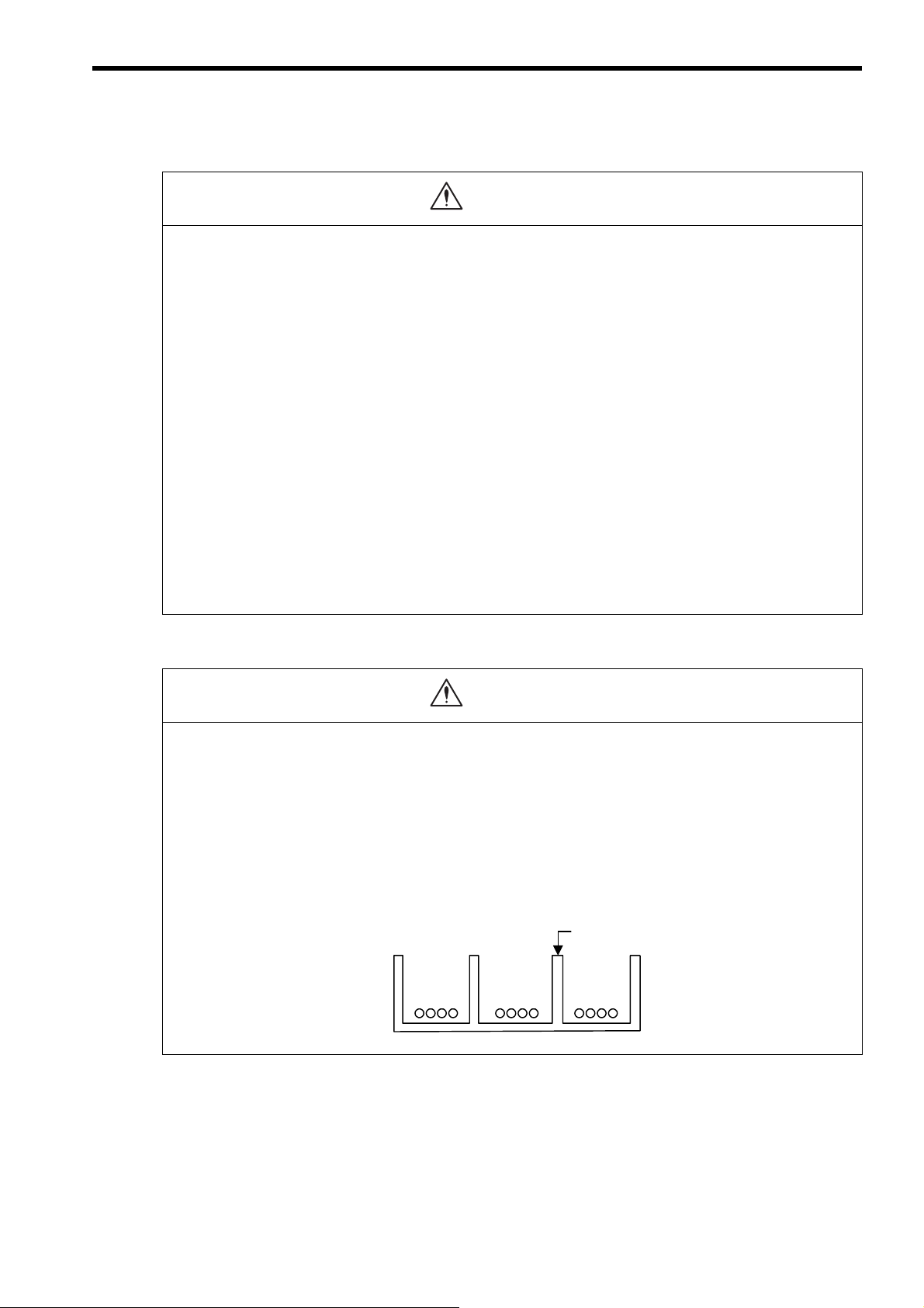
CAUTION
CAUTION
鉄板製のセパレータ
ディジタル
入出力信号
ケーブル
一般制御回路
のケーブル
動力回路
の
ケーブル
外部配線
の分離例
Example of Separated External Cables
Steel separator
Power
circuit
cables
General
control circuit cables
Digital I/O
signal
cables
Wiring
Check the wiring to be sure it has been performed correctly.
There is a risk of motor run-away, injury, or an accident.
Always use a power supply of the specified voltage.
There is a risk of burning.
In places with poor power supply conditions, take all steps necessary to ensure that the input power supply
is within the specified voltage range.
There is a risk of device damage.
Install breakers and other safety measure to provide protection against shorts in external wiring.
There is a risk of fire.
Provide sufficient shielding when using the MP2300S in the following locations.
There is a risk of device damage.
Noise, such as from static electricity
Strong electromagnetic or magnetic fields
Radiation
Near to power lines
When connecting the battery, connect the polarity correctly.
There is a risk of battery damage or explosion.
Only qualified safety-trained personnel should replace the battery.
If the battery is replaced incorrectly, machine malfunction or damage, electric shock, or injury may result.
When replacing the battery, do not touch the electrodes.
Static electricity may damage the electrodes.
Selecting, Separating, and Laying External Cables
Consider the following items when selecting the I/O signal lines (external cables) to connect the MP2300S
to external devices.
Mechanical strength
Noise interference
Wiring distance
Signal voltage, etc.
Separate the I/O signal lines from the power lines both inside and outside the control box to reduce the
influence of noise from the power lines.
If the I/O signal lines and power lines are not separated properly, malfunctioning may result.
ix
Page 10

CAUTION
CAUTION
Maintenance and Inspection Precautions
Do not attempt to disassemble the MP2300S.
There is a risk of electrical shock or injury.
Do not change wiring while power is being supplied.
There is a risk of electrical shock or injury.
When replacing the MP2300S, restart operation only after transferring the programs and parameters from
the old Module to the new Module.
There is a risk of device damage.
Disposal Precautions
Dispose of the MP2300S as general industrial waste.
A lithium battery is built into the MP2300S. After replacing the battery, dispose of the old battery separate
from regular waste and in accordance with local regulations.
General Precautions
The products shown in illustrations in this manual are sometimes shown without covers or protective
guards. Always replace the cover or protective guard as specified first, and then operate the products in
accordance with the manual.
The drawings presented in this manual are typical examples and may not match the product you
received.
If the manual must be ordered due to loss or damage, inform your nearest Yaskawa representative or
one of the offices listed on the back of this manual.
Observe the following general precautions
to ensure safe application.
x
Page 11

Warranty
( 1 ) Details of Warranty
Warranty Period
The warranty period for a product that was purchased (hereinafter called “delivered product”) is one year from the time
of delivery to the location specified by the customer or 18 months from the time of shipment from the Yaskawa factory,
whichever is sooner.
Warranty Scope
Yaskawa shall replace or repair a defective product free of charge if a defect attributable to Yaskawa occurs during the
warranty period above. This warranty does not cover defects caused by the delivered product reaching the end of its
service life and replacement of parts that require replacement or that have a limited service life.
This warranty does not cover failures that result from any of the following causes.
1. Improper handling, abuse, or use in unsuitable conditions or in environments not described in product catalogs or
manuals, or in any separately agreed-upon specifications
2. Causes not attributable to the delivered product itself
3. Modifications or repairs not performed by Yaskawa
4. Abuse of the delivered product in a manner in which it was not originally intended
5. Causes that were not foreseeable with the scientific and technological understanding at the time of shipment from
Ya sk a wa
6. Events for which Yaskawa is not responsible, such as natural or human-made disasters
( 2 ) Limitations of Liability
1. Yaskawa shall in no event be responsible for any damage or loss of opportunity to the customer that arises due to
failure of the delivered product.
2. Yaskawa shall not be responsible for any programs (including parameter settings) or the results of program execution of the programs provided by the user or by a third party for use with programmable Yaskawa products.
3. The information described in product catalogs or manuals is provided for the purpose of the customer purchasing
the appropriate product for the intended application. The use thereof does not guarantee that there are no infringements of intellectual property rights or other proprietary rights of Yaskawa or third parties, nor does it construe a
license.
4. Yaskawa shall not be responsible for any damage arising from infringements of intellectual property rights or other
proprietary rights of third parties as a result of using the information described in catalogs or manuals.
xi
Page 12

( 3 ) Suitability for Use
1. It is the customer’s responsibility to confirm conformity with any standards, codes, or regulations that apply if the
Yaskawa product is used in combination with any other products.
2. The customer must confirm that the Yaskawa product is suitable for the systems, machines, and equipment used by
the customer.
3. Consult with Yaskawa to determine whether use in the following applications is acceptable. If use in the application
is acceptable, use the product with extra allowance in ratings and specifications, and provide safety measures to
minimize hazards in the event of failure.
• Outdoor use, use involving potential chemical contamination or electrical interference, or use in conditions or
environments not described in product catalogs or manuals
• Nuclear energy control systems, combustion systems, railroad systems, aviation systems, vehicle systems,
medical equipment, amusement machines, and installations subject to separate industry or government regulations
• Systems, machines, and equipment that may present a risk to life or property
• Systems that require a high degree of reliability, such as systems that supply gas, water, or electricity, or systems that operate continuously 24 hours a day
• Other systems that require a similar high degree of safety
4. Never use the product for an application involving serious risk to life or property without first ensuring that the system is designed to secure the required level of safety with risk warnings and redundancy, and that the Yaskawa
product is properly rated and installed.
5. The circuit examples and other application examples described in product catalogs and manuals are for reference.
Check the functionality and safety of the actual devices and equipment to be used before using the product.
6. Read and understand all use prohibitions and precautions, and operate the Yaskawa product correctly to prevent
accidental harm to third parties.
( 4 ) Specifications Change
The names, specifications, appearance, and accessories of products in product catalogs and manuals may be changed at
any time based on improvements and other reasons. The next editions of the revised catalogs or manuals will be published with updated code numbers. Consult with your Yaskawa representative to confirm the actual specifications
before purchasing a product.
xii
Page 13

Contents
Using this Manual - - - - - - - - - - - - - - - - - - - - - - - - - - - - - - - - - - - - - - - - - - - - - - - - - - - - - - - iii
Safety Information - - - - - - - - - - - - - - - - - - - - - - - - - - - - - - - - - - - - - - - - - - - - - - - - - - - - - - - vi
Safety Precautions - - - - - - - - - - - - - - - - - - - - - - - - - - - - - - - - - - - - - - - - - - - - - - - - - - - - - - vii
Warranty - - - - - - - - - - - - - - - - - - - - - - - - - - - - - - - - - - - - - - - - - - - - - - - - - - - - - - - - - - - - - xi
1 Overview- - - - - - - - - - - - - - - - - - - - - - - - - - - - - - - - - - - - - - - - - - - - - - - - - - 1-1
1.1 MP2300S Features- - - - - - - - - - - - - - - - - - - - - - - - - - - - - - - - - - - - - - - - - - - 1-2
1.2 MP2300S Configuration - - - - - - - - - - - - - - - - - - - - - - - - - - - - - - - - - - - - - - - 1-3
1.2.1 Basic Module Appearance - - - - - - - - - - - - - - - - - - - - - - - - - - - - - - - - - - - - - - - - - - - - - - - - 1-3
1.2.2 MP2300S Modules - - - - - - - - - - - - - - - - - - - - - - - - - - - - - - - - - - - - - - - - - - - - - - - - - - - - - 1-4
1.3 System Configuration - - - - - - - - - - - - - - - - - - - - - - - - - - - - - - - - - - - - - - - - - 1-5
1.3.1 Example - - - - - - - - - - - - - - - - - - - - - - - - - - - - - - - - - - - - - - - - - - - - - - - - - - - - - - - - - - - - - 1-5
1.3.2 Example of Distributed Synchronizing System- - - - - - - - - - - - - - - - - - - - - - - - - - - - - - - - - - 1-6
1.4 MECHATROLINK Compatible Devices - - - - - - - - - - - - - - - - - - - - - - - - - - - - - 1-7
1.4.1 MECHATROLINK-I/II Compatible Devices- - - - - - - - - - - - - - - - - - - - - - - - - - - - - - - - - - - - - 1-7
1.4.2 MECHATROLINK-III Compatible Devices - - - - - - - - - - - - - - - - - - - - - - - - - - - - - - - - - - - - - 1-8
1.5 Cables and Accessories - - - - - - - - - - - - - - - - - - - - - - - - - - - - - - - - - - - - - - - 1-9
1.5.1 Cables - - - - - - - - - - - - - - - - - - - - - - - - - - - - - - - - - - - - - - - - - - - - - - - - - - - - - - - - - - - - - - 1-9
1.5.2 Accessories and Options - - - - - - - - - - - - - - - - - - - - - - - - - - - - - - - - - - - - - - - - - - - - - - - - 1-10
1.5.3 Software (Programming Tool) - - - - - - - - - - - - - - - - - - - - - - - - - - - - - - - - - - - - - - - - - - - - - 1-10
2 Specifications and Functions- - - - - - - - - - - - - - - - - - - - - - - - - - - - - - - - - - - - 2-1
2.1 Specifications- - - - - - - - - - - - - - - - - - - - - - - - - - - - - - - - - - - - - - - - - - - - - - - 2-2
2.1.1 General Specifications - - - - - - - - - - - - - - - - - - - - - - - - - - - - - - - - - - - - - - - - - - - - - - - - - - - 2-2
2.1.2 Product Specifications - - - - - - - - - - - - - - - - - - - - - - - - - - - - - - - - - - - - - - - - - - - - - - - - - - - 2-3
2.1.3 Function Lists - - - - - - - - - - - - - - - - - - - - - - - - - - - - - - - - - - - - - - - - - - - - - - - - - - - - - - - - - 2-4
2.2 Basic Module - - - - - - - - - - - - - - - - - - - - - - - - - - - - - - - - - - - - - - - - - - - - - - - 2-7
2.2.1 Outline of Functions- - - - - - - - - - - - - - - - - - - - - - - - - - - - - - - - - - - - - - - - - - - - - - - - - - - - - 2-7
2.2.2 External Appearance, LED Indicators, and Switch Settings - - - - - - - - - - - - - - - - - - - - - - - - - 2-8
2.2.3 Specifications - - - - - - - - - - - - - - - - - - - - - - - - - - - - - - - - - - - - - - - - - - - - - - - - - - - - - - - - 2-11
2.2.4 218IFA Module (Ethernet) - - - - - - - - - - - - - - - - - - - - - - - - - - - - - - - - - - - - - - - - - - - - - - - 2-12
2.2.5 Built-in SVB Module- - - - - - - - - - - - - - - - - - - - - - - - - - - - - - - - - - - - - - - - - - - - - - - - - - - - 2-31
2.2.6 SVR Virtual Motion Module- - - - - - - - - - - - - - - - - - - - - - - - - - - - - - - - - - - - - - - - - - - - - - - 2-48
2.2.7 M-EXECUTOR Module (Motion Program Executor) - - - - - - - - - - - - - - - - - - - - - - - - - - - - - 2-51
2.3 Option Module - - - - - - - - - - - - - - - - - - - - - - - - - - - - - - - - - - - - - - - - - - - - - - 2-62
2.3.1 Option Module Overview List - - - - - - - - - - - - - - - - - - - - - - - - - - - - - - - - - - - - - - - - - - - - - 2-62
2.4 External Appearance - - - - - - - - - - - - - - - - - - - - - - - - - - - - - - - - - - - - - - - - - 2-64
2.4.1 Basic Module - - - - - - - - - - - - - - - - - - - - - - - - - - - - - - - - - - - - - - - - - - - - - - - - - - - - - - - - 2-64
2.4.2 Basic Module with Metal Fittings - - - - - - - - - - - - - - - - - - - - - - - - - - - - - - - - - - - - - - - - - - - 2-65
3 Mounting and Wiring - - - - - - - - - - - - - - - - - - - - - - - - - - - - - - - - - - - - - - - - - 3-1
3.1 Mounting MP2300S - - - - - - - - - - - - - - - - - - - - - - - - - - - - - - - - - - - - - - - - - - 3-2
3.1.1 Method- - - - - - - - - - - - - - - - - - - - - - - - - - - - - - - - - - - - - - - - - - - - - - - - - - - - - - - - - - - - - - 3-2
3.1.2 MP2300S Mount Direction - - - - - - - - - - - - - - - - - - - - - - - - - - - - - - - - - - - - - - - - - - - - - - - - 3-7
3.1.3 Space Required for Mounting MP2300S - - - - - - - - - - - - - - - - - - - - - - - - - - - - - - - - - - - - - - 3-8
3.1.4 Replacing and Adding Optional Modules - - - - - - - - - - - - - - - - - - - - - - - - - - - - - - - - - - - - - - 3-9
xiii
Page 14

3.2 Basic Module Connections - - - - - - - - - - - - - - - - - - - - - - - - - - - - - - - - - - - - - 3-12
3.2.1 Connectors - - - - - - - - - - - - - - - - - - - - - - - - - - - - - - - - - - - - - - - - - - - - - - - - - - - - - - - - - 3-12
3.2.2 Power Supply Connector- - - - - - - - - - - - - - - - - - - - - - - - - - - - - - - - - - - - - - - - - - - - - - - - 3-13
3.2.3 MECHATROLINK Connectors - - - - - - - - - - - - - - - - - - - - - - - - - - - - - - - - - - - - - - - - - - - - 3-14
3.2.4 Ethernet Connector Details - - - - - - - - - - - - - - - - - - - - - - - - - - - - - - - - - - - - - - - - - - - - - - 3-19
3.2.5 RLY OUT Connector Details - - - - - - - - - - - - - - - - - - - - - - - - - - - - - - - - - - - - - - - - - - - - - 3-23
3.2.6 System Connection Example - - - - - - - - - - - - - - - - - - - - - - - - - - - - - - - - - - - - - - - - - - - - - 3-25
4 System Start Up and Easy Programming - - - - - - - - - - - - - - - - - - - - - - - - - - - 4-1
4.1 System Startup Overview - - - - - - - - - - - - - - - - - - - - - - - - - - - - - - - - - - - - - - - 4-2
4.2 Preparation (step 1) - - - - - - - - - - - - - - - - - - - - - - - - - - - - - - - - - - - - - - - - - - - 4-3
4.2.1 Wiring - - - - - - - - - - - - - - - - - - - - - - - - - - - - - - - - - - - - - - - - - - - - - - - - - - - - - - - - - - - - - - 4-3
4.2.2 Self Configuration - - - - - - - - - - - - - - - - - - - - - - - - - - - - - - - - - - - - - - - - - - - - - - - - - - - - - - 4-5
4.2.3 Test Operation - - - - - - - - - - - - - - - - - - - - - - - - - - - - - - - - - - - - - - - - - - - - - - - - - - - - - - - - 4-6
4.3 Programming (step 2) - - - - - - - - - - - - - - - - - - - - - - - - - - - - - - - - - - - - - - - - - - 4-9
4.3.1 Programming Procedure - - - - - - - - - - - - - - - - - - - - - - - - - - - - - - - - - - - - - - - - - - - - - - - - - 4-9
4.4 Executing Motion (step 3) - - - - - - - - - - - - - - - - - - - - - - - - - - - - - - - - - - - - - - 4-11
4.4.1 Registering Program Execution - - - - - - - - - - - - - - - - - - - - - - - - - - - - - - - - - - - - - - - - - - - 4-11
4.4.2 Starting a Motion Program Using the Operation Control Panel - - - - - - - - - - - - - - - - - - - - - 4-12
4.5 Starting Motion Program from an External Signal- - - - - - - - - - - - - - - - - - - - - - 4-13
4.5.1 Overview - - - - - - - - - - - - - - - - - - - - - - - - - - - - - - - - - - - - - - - - - - - - - - - - - - - - - - - - - - - 4-13
4.5.2 Required Equipment - - - - - - - - - - - - - - - - - - - - - - - - - - - - - - - - - - - - - - - - - - - - - - - - - - - 4-13
4.5.3 Creation Procedure- - - - - - - - - - - - - - - - - - - - - - - - - - - - - - - - - - - - - - - - - - - - - - - - - - - - 4-15
5 Outline of Motion Control Systems - - - - - - - - - - - - - - - - - - - - - - - - - - - - - - - 5-1
5.1 Startup Sequence and Basic Operation - - - - - - - - - - - - - - - - - - - - - - - - - - - - - 5-2
5.1.1 DIP Switch Settings - - - - - - - - - - - - - - - - - - - - - - - - - - - - - - - - - - - - - - - - - - - - - - - - - - - - 5-2
5.1.2 Startup Sequence- - - - - - - - - - - - - - - - - - - - - - - - - - - - - - - - - - - - - - - - - - - - - - - - - - - - - - 5-3
5.1.3 Startup Sequence Operation Details- - - - - - - - - - - - - - - - - - - - - - - - - - - - - - - - - - - - - - - - - 5-4
5.2 User Programs- - - - - - - - - - - - - - - - - - - - - - - - - - - - - - - - - - - - - - - - - - - - - - - 5-5
5.2.1 Types and Execution Timing of User Program- - - - - - - - - - - - - - - - - - - - - - - - - - - - - - - - - - 5-5
5.2.2 Motion Programs - - - - - - - - - - - - - - - - - - - - - - - - - - - - - - - - - - - - - - - - - - - - - - - - - - - - - - 5-6
5.2.3 Sequence Program- - - - - - - - - - - - - - - - - - - - - - - - - - - - - - - - - - - - - - - - - - - - - - - - - - - - 5-27
5.2.4 Ladder Drawings (DWG) - - - - - - - - - - - - - - - - - - - - - - - - - - - - - - - - - - - - - - - - - - - - - - - - 5-30
5.3 Registers - - - - - - - - - - - - - - - - - - - - - - - - - - - - - - - - - - - - - - - - - - - - - - - - - - 5-35
5.3.1 Types of Registers - - - - - - - - - - - - - - - - - - - - - - - - - - - - - - - - - - - - - - - - - - - - - - - - - - - - 5-35
5.3.2 Data Types - - - - - - - - - - - - - - - - - - - - - - - - - - - - - - - - - - - - - - - - - - - - - - - - - - - - - - - - - 5-38
5.3.3 How to Use Subscripts i, j - - - - - - - - - - - - - - - - - - - - - - - - - - - - - - - - - - - - - - - - - - - - - - - 5-39
5.3.4 Register Designation- - - - - - - - - - - - - - - - - - - - - - - - - - - - - - - - - - - - - - - - - - - - - - - - - - - 5-40
5.4 Self-configuration - - - - - - - - - - - - - - - - - - - - - - - - - - - - - - - - - - - - - - - - - - - - 5-41
5.4.1 How to Execute Self-Configuration - - - - - - - - - - - - - - - - - - - - - - - - - - - - - - - - - - - - - - - - - 5-42
5.4.2 Definition Information Updated with Self-Configuration - - - - - - - - - - - - - - - - - - - - - - - - - - - 5-50
5.5 Precaution on Using MP2300S - - - - - - - - - - - - - - - - - - - - - - - - - - - - - - - - - - 5-53
5.5.1 Precautions when User Definition File is Configured/Changed - - - - - - - - - - - - - - - - - - - - - 5-53
5.5.2 Setting or Changing Module Configuration Definition Files - - - - - - - - - - - - - - - - - - - - - - - - 5-54
5.5.3 Setting and Changing the Scan Time - - - - - - - - - - - - - - - - - - - - - - - - - - - - - - - - - - - - - - - 5-55
xiv
6 Built-in Ethernet Communications - - - - - - - - - - - - - - - - - - - - - - - - - - - - - - - - 6-1
6.1 Communication Methods- - - - - - - - - - - - - - - - - - - - - - - - - - - - - - - - - - - - - - - - 6-2
Page 15

6.2 Communication with Other MP Series - - - - - - - - - - - - - - - - - - - - - - - - - - - - - 6-3
6.2.1 When the MP2300S Acts as Slave (automatic receive function is used) - - - - - - - - - - - - - - - - 6-3
6.2.2 When the MP2300S Acts as Slave (ladder program which uses a MSG-RCV function) - - - - 6-17
6.2.3 When the MP2300S Acts as Master (I/O message communication function is used) - - - - - - 6-36
6.2.4 When the MP2300S Acts as Master (ladder program which uses a MSG-SND function) - - - 6-49
6.3 Communication with Touch Panel- - - - - - - - - - - - - - - - - - - - - - - - - - - - - - - - - 6-65
6.3.1 When the MP2300S Acts as Slave (automatic receive function is used) - - - - - - - - - - - - - - - 6-65
6.4 Communication with PLC Manufactured by Mitsubishi Electric Corporation
(MELSEC protocol) - - - - - - - - - - - - - - - - - - - - - - - - - - - - - - - - - - - - - - - - - - 6-75
6.4.1 When the MP2300S Acts as Slave (automatic receive function is used) - - - - - - - - - - - - - - - 6-75
6.4.2 When the MP2300S Acts as Master (I/O message communication function is used) - - - - - - 6-83
7 Slave CPU Synchronous Function- - - - - - - - - - - - - - - - - - - - - - - - - - - - - - - - 7-1
7.1 Function - - - - - - - - - - - - - - - - - - - - - - - - - - - - - - - - - - - - - - - - - - - - - - - - - - 7-2
7.2 Requirements and Setting of Execution - - - - - - - - - - - - - - - - - - - - - - - - - - - - 7-3
7.2.1 Supported Version- - - - - - - - - - - - - - - - - - - - - - - - - - - - - - - - - - - - - - - - - - - - - - - - - - - - - - 7-3
7.2.2 Requirements to Execute Slave CPU Synchronous Function- - - - - - - - - - - - - - - - - - - - - - - - 7-3
7.2.3 How to Set up Slave CPU Synchronous Function- - - - - - - - - - - - - - - - - - - - - - - - - - - - - - - - 7-4
7.2.4 How to Execute Slave CPU Synchronous Function - - - - - - - - - - - - - - - - - - - - - - - - - - - - - - 7-7
7.3 Operation- - - - - - - - - - - - - - - - - - - - - - - - - - - - - - - - - - - - - - - - - - - - - - - - - - 7-9
7.3.1 Input/Output Register- - - - - - - - - - - - - - - - - - - - - - - - - - - - - - - - - - - - - - - - - - - - - - - - - - - - 7-9
7.3.2 How to Determine Slave CPU Synchronous State - - - - - - - - - - - - - - - - - - - - - - - - - - - - - - 7-15
7.3.3 Calculation of Slave CPU Synchronous Delay Time - - - - - - - - - - - - - - - - - - - - - - - - - - - - - 7-16
7.3.4 How to Use Scan Counter - - - - - - - - - - - - - - - - - - - - - - - - - - - - - - - - - - - - - - - - - - - - - - - 7-17
7.3.5 How to Determine Input Error - - - - - - - - - - - - - - - - - - - - - - - - - - - - - - - - - - - - - - - - - - - - - 7-18
7.3.6 Management to Resume Slave CPU Synchronization - - - - - - - - - - - - - - - - - - - - - - - - - - - - 7-24
7.4 Precautions - - - - - - - - - - - - - - - - - - - - - - - - - - - - - - - - - - - - - - - - - - - - - - - - 7-28
7.4.1 Precautions on Usage - - - - - - - - - - - - - - - - - - - - - - - - - - - - - - - - - - - - - - - - - - - - - - - - - - 7-28
7.4.2 Effect of Error on Slave CPU Synchronous Operation- - - - - - - - - - - - - - - - - - - - - - - - - - - - 7-29
8 Maintenance and Inspection - - - - - - - - - - - - - - - - - - - - - - - - - - - - - - - - - - - - 8-1
8.1 Daily Inspections - - - - - - - - - - - - - - - - - - - - - - - - - - - - - - - - - - - - - - - - - - - - 8-2
8.2 Regular Inspections - - - - - - - - - - - - - - - - - - - - - - - - - - - - - - - - - - - - - - - - - - 8-3
8.3 Replacing the Basic Module Battery - - - - - - - - - - - - - - - - - - - - - - - - - - - - - - - 8-4
9 Troubleshooting- - - - - - - - - - - - - - - - - - - - - - - - - - - - - - - - - - - - - - - - - - - - - 9-1
9.1 Basic Flow of Troubleshooting - - - - - - - - - - - - - - - - - - - - - - - - - - - - - - - - - - - 9-2
9.2 LED Indicator Meanings - - - - - - - - - - - - - - - - - - - - - - - - - - - - - - - - - - - - - - - 9-3
9.3 Problem Classification- - - - - - - - - - - - - - - - - - - - - - - - - - - - - - - - - - - - - - - - - 9-4
9.3.1 Overview - - - - - - - - - - - - - - - - - - - - - - - - - - - - - - - - - - - - - - - - - - - - - - - - - - - - - - - - - - - - 9-4
9.3.2 MP2300S Error Check Flowchart - - - - - - - - - - - - - - - - - - - - - - - - - - - - - - - - - - - - - - - - - - - 9-5
9.4 Troubleshooting Details - - - - - - - - - - - - - - - - - - - - - - - - - - - - - - - - - - - - - - - - 9-6
9.4.1 Operation Errors - - - - - - - - - - - - - - - - - - - - - - - - - - - - - - - - - - - - - - - - - - - - - - - - - - - - - - - 9-6
9.4.2 I/O Errors - - - - - - - - - - - - - - - - - - - - - - - - - - - - - - - - - - - - - - - - - - - - - - - - - - - - - - - - - - - - 9-9
9.4.3 Watchdog Timer Timeout Errors - - - - - - - - - - - - - - - - - - - - - - - - - - - - - - - - - - - - - - - - - - - 9-10
9.4.4 Module Synchronization Errors (Ver. 2.75 or Later)- - - - - - - - - - - - - - - - - - - - - - - - - - - - - - 9-10
9.4.5 System Errors - - - - - - - - - - - - - - - - - - - - - - - - - - - - - - - - - - - - - - - - - - - - - - - - - - - - - - - - 9-11
xv
Page 16

Appendices - - - - - - - - - - - - - - - - - - - - - - - - - - - - - - - - - - - - - - - - - - - - - - - - A-1
Appendix A System Registers Lists - - - - - - - - - - - - - - - - - - - - - - - - - - - - - - - - - - A-3
A.1 System Service Registers - - - - - - - - - - - - - - - - - - - - - - - - - - - - - - - - - - - - - - - - - - - - - - - - - A-3
A.2 System Status - - - - - - - - - - - - - - - - - - - - - - - - - - - - - - - - - - - - - - - - - - - - - - - - - - - - - - - - - A-6
A.3 System Error Status - - - - - - - - - - - - - - - - - - - - - - - - - - - - - - - - - - - - - - - - - - - - - - - - - - - - - A-7
A.4 User Operation Error Status - - - - - - - - - - - - - - - - - - - - - - - - - - - - - - - - - - - - - - - - - - - - - - - - A-9
A.5 System Service Execution Status - - - - - - - - - - - - - - - - - - - - - - - - - - - - - - - - - - - - - - - - - - - A-10
A.6 User Operation Error Status Details - - - - - - - - - - - - - - - - - - - - - - - - - - - - - - - - - - - - - - - - - A-11
A.7 System I/O Error Status- - - - - - - - - - - - - - - - - - - - - - - - - - - - - - - - - - - - - - - - - - - - - - - - - - A-12
A.8 Compact Flash Card-Related System Registers
(CPU-02 and CPU-03 Modules for the MP2200 Only) - - - - - - - - - - - - - - - - - - - - - - - - - - - - A-13
A.9 Interrupt Status - - - - - - - - - - - - - - - - - - - - - - - - - - - - - - - - - - - - - - - - - - - - - - - - - - - - - - - - A-14
A.10 Module Information - - - - - - - - - - - - - - - - - - - - - - - - - - - - - - - - - - - - - - - - - - - - - - - - - - - - A-15
A.11 MPU-01 System Status - - - - - - - - - - - - - - - - - - - - - - - - - - - - - - - - - - - - - - - - - - - - - - - - - A-16
A.12 Motion Program Information - - - - - - - - - - - - - - - - - - - - - - - - - - - - - - - - - - - - - - - - - - - - - - A-17
Appendix B SERVOPACK Parameter Data Flow- - - - - - - - - - - - - - - - - - - - - - - - A-20
B.1 Operations and Parameter Data Flow - - - - - - - - - - - - - - - - - - - - - - - - - - - - - - - - - - - - - - - - A-20
Appendix C Initializing SERVOPACKs - - - - - - - - - - - - - - - - - - - - - - - - - - - - - - - A-29
Appendix D Initializing the Absolute Encoder - - - - - - - - - - - - - - - - - - - - - - - - - - A-30
D.1 Σ-V SERVOPACK - - - - - - - - - - - - - - - - - - - - - - - - - - - - - - - - - - - - - - - - - - - - - - - - - - - - - - A-30
D.2 Σ-III SERVOPACK - - - - - - - - - - - - - - - - - - - - - - - - - - - - - - - - - - - - - - - - - - - - - - - - - - - - - A-31
D.3 Σ-II SERVOPACK - - - - - - - - - - - - - - - - - - - - - - - - - - - - - - - - - - - - - - - - - - - - - - - - - - - - - - A-32
D.4 Σ-I SERVOPACK - - - - - - - - - - - - - - - - - - - - - - - - - - - - - - - - - - - - - - - - - - - - - - - - - - - - - - A-34
Appendix E Motion Parameter Details - - - - - - - - - - - - - - - - - - - - - - - - - - - - - - - A-36
E.1 Fixed Parameter List - - - - - - - - - - - - - - - - - - - - - - - - - - - - - - - - - - - - - - - - - - - - - - - - - - - - A-36
E.2 Setting Parameter List - - - - - - - - - - - - - - - - - - - - - - - - - - - - - - - - - - - - - - - - - - - - - - - - - - - A-38
E.3 Monitoring Parameter List - - - - - - - - - - - - - - - - - - - - - - - - - - - - - - - - - - - - - - - - - - - - - - - - A-43
Appendix F Simple Connection Function of the Engineering Tool - - - - - - - - - - - - A-47
F.1 Preparation - - - - - - - - - - - - - - - - - - - - - - - - - - - - - - - - - - - - - - - - - - - - - - - - - - - - - - - - - - - A-47
F.2 Procedure- - - - - - - - - - - - - - - - - - - - - - - - - - - - - - - - - - - - - - - - - - - - - - - - - - - - - - - - - - - - A-47
Appendix G MSG-SND/MSG-RCV Functions (Ethernet) - - - - - - - - - - - - - - - - - - A-51
G.1 Message Transmit Function (MSG-SND)- - - - - - - - - - - - - - - - - - - - - - - - - - - - - - - - - - - - - - A-51
G.2 Message Receive Function (MSG-RCV) - - - - - - - - - - - - - - - - - - - - - - - - - - - - - - - - - - - - - - A-86
G.3 Communication Buffer Channel - - - - - - - - - - - - - - - - - - - - - - - - - - - - - - - - - - - - - - - - - - - A-118
Appendix H Optional Functions - - - - - - - - - - - - - - - - - - - - - - - - - - - - - - - - - - - - A-120
H.1 Clearing D Registers at Startup - - - - - - - - - - - - - - - - - - - - - - - - - - - - - - - - - - - - - - - - - - - A-120
H.2 Security - - - - - - - - - - - - - - - - - - - - - - - - - - - - - - - - - - - - - - - - - - - - - - - - - - - - - - - - - - - - A-121
H.3 Battery Backup for Table Data - - - - - - - - - - - - - - - - - - - - - - - - - - - - - - - - - - - - - - - - - - - - A-129
Appendix I Installing MPE720 Version 6 - - - - - - - - - - - - - - - - - - - - - - - - - - - - - - A-133
INDEX
Revision History
xvi
Page 17

Overview
1
Overview
This chapter explains an overview and features of the MP2300S Machine Controller.
1.1 MP2300S Features - - - - - - - - - - - - - - - - - - - - - - - - - - - - - - - - - - - - - - - -1-2
1.2 MP2300S Configuration - - - - - - - - - - - - - - - - - - - - - - - - - - - - - - - - - - - -1-3
1.2.1 Basic Module Appearance - - - - - - - - - - - - - - - - - - - - - - - - - - - - - - - - - - - - - - - - - - - 1-3
1.2.2 MP2300S Modules - - - - - - - - - - - - - - - - - - - - - - - - - - - - - - - - - - - - - - - - - - - - - - - - 1-4
1.3 System Configuration - - - - - - - - - - - - - - - - - - - - - - - - - - - - - - - - - - - - - -1-5
1.3.1 Example - - - - - - - - - - - - - - - - - - - - - - - - - - - - - - - - - - - - - - - - - - - - - - - - - - - - - - - - 1-5
1.3.2 Example of Distributed Synchronizing System - - - - - - - - - - - - - - - - - - - - - - - - - - - - - 1-6
1.4 MECHATROLINK Compatible Devices - - - - - - - - - - - - - - - - - - - - - - - - - -1-7
1.4.1 MECHATROLINK-I/II Compatible Devices - - - - - - - - - - - - - - - - - - - - - - - - - - - - - - - - 1-7
1.4.2 MECHATROLINK-III Compatible Devices - - - - - - - - - - - - - - - - - - - - - - - - - - - - - - - - 1-8
1.5 Cables and Accessories - - - - - - - - - - - - - - - - - - - - - - - - - - - - - - - - - - - -1-9
1.5.1 Cables - - - - - - - - - - - - - - - - - - - - - - - - - - - - - - - - - - - - - - - - - - - - - - - - - - - - - - - - - 1-9
1.5.2 Accessories and Options - - - - - - - - - - - - - - - - - - - - - - - - - - - - - - - - - - - - - - - - - - - 1-10
1.5.3 Software (Programming Tool) - - - - - - - - - - - - - - - - - - - - - - - - - - - - - - - - - - - - - - - - 1-10
1-1
Page 18

1.1 MP2300S Features
1.1 MP2300S Features
The MP2300S is a small all-in-one machine controller, and successor to the MP2000 series in function and performance. It is characterized by the following standard features:
Standard Feature Motion Network MECHATROLINK-II
• Controls up to 16 axes of servos supporting MECHATROLINK-II.
• Connects up to 21 stations including I/Os.
Standard Feature Ethernet (100 Mbps)
• Allows high-speed communications with the engineering tool MPE720.
• Enables communication without a ladder program by using a touch panel (automatic receive function).
• Enables communication without a ladder program by using an upper PLC (I/O message communication function).
Scalability Ensured in Preparation for Single Optional Slot
• Single optional slot ensures scalability. The existing optional modules of MP2000 series are available.
• An optional module allows the use of various open networks, such as CC-Link, DeviceNet, and PROFIBUS.
• Connecting an SVB-01 module to the optional slot allows the synchronized control of up to 32 axes of servos.
Capable of a Synchronous Distributed System with MECHATROLINK
• The MP2300S has a CPU synchronous function using MECHATROLINK communications. This is a new function in the MP2000 series Machine Controllers.
• A sync operation between slave controllers is made possible by connecting the MP2300S as a slave with an
MP2000 series model as a master via MECHATROLINK-II.
• The controller's load balancing affords a high-speed synchronization of multi-axis motions.
Simple Programming
• The operation procedures needed before performing a motion operation are significantly reduced.
• You can start up a motion program from an upper PLC without the need for programming, simply by creating the
motion program and registering execution orders.
1-2
Page 19

Overview
1.2 MP2300S Configuration
The MP2300S is configured with one Basic Module and an optional slot.
1.2.1 Basic Module Appearance
The following figure shows the external appearance of the Basic Module with metal fittings for attachment.
Also, the values in the figure do not include the length of metal fittings.
Metal fittings
for attachment
1.2 MP2300S Configuration
1.2.1 Basic Module Appearance
64 mm
LED
(8 points)
DIP switch
(6 points+4 points)
Battery cover
MECHATROLINK-Τ
connector
(1 line, 2 ports)
2-pole connector
(RLY OUT)
3-pole connector
(24-V power supply)
MP
$#66'4;
23
0
;#5-#9#
M-I/II
0
S
4&;
#./
/6:
64:
5612
572
+06
%0()
/10
6'56
470
'44
$#6
+2
59
01
10
LIO
01
.& .&
.&
.&
.&
/1&'
I/O
.&
.&
.&
130 mm
59
'
+06
6'56
E
LINK
/
thernet
01
10
&%
8
&%
0V
4.;
176
'
108 mm
Ethernet connector
with LED
Optional slot
1-3
Page 20

1.2 MP2300S Configuration
1.2.2 MP2300S Modules
1.2.2 MP2300S Modules
The following table shows the names and specifications of the Basic Module and Optional Modules.
Group Name Description Model Specifications
Basic Module
Motion
Modules
I/O Modules
Optional
Modules
Communication
Modules
Basic Module MP2300S JAPMC-MP2300S-E
MECHATROLINK
Motion Module
Analog Output Motion
Module
Pulse Output Motion
Module
I/O Module
Output Module DO-01 JAPMC-DO2300(-E) 64 outputs (sink mode output)
Analog Input Module AI-01 JAPMC-AN2300(-E) Analog input, 8 channels
Analog Output Module AO-01 JAPMC-AN2310-E Analog input, 4 channels
Counter Module CNTR-01 JAPMC-PL2300-E Reversible counter, 2 channels
Ethernet Communication Module
General-purpose Serial
Communication
Module
DeviceNet
Communication
Module
PROFIBUS
Communication
Module
FL-net Communication
Module
EtherNet/IP Communication Module
MPLINK/CP-215
Communication
Module
MECHATROLINK-I and -II Interface
Ethernet communications
SVB-01 JAPMC-MC2310(-E)
SVC-01 JAPMC-MC2320-E
SVA-01 JAPMC-MC2300(-E) Analog output, 2 axes maximum
PO-01 JAPMC-PL2310-E Pulse output, 4 axes maximum
LIO-01 JAPMC-IO2300(-E)
LIO-02 JAPMC-IO2301(-E)
LIO-04 JAPMC-IO2303(-E) 32 inputs, 32 outputs (sink mode output)
LIO-05 JAPMC-IO2304(-E) 32 inputs, 32 outputs (source mode output)
LIO-06 JAPMC-IO2305-E
218IF-01 JAPMC-CM2300(-E) RS-232C and Ethernet communications
218IF-02 JAPMC-CM2302(-E)
217IF-01 JAPMC-CM2310(-E)
260IF-01 JAPMC-CM2320(-E) RS-232C and DeviceNet communications
261IF-01 JAPMC-CM2330(-E) RS-232C and PROFIBUS communications
262IF-01 JAPMC-CM2303-E FL-net communications
263IF-01 JAPMC-CM2304-E EtherNet/IP communications
215AIF-01
JAPMC-CM2360(-E)
JAPMC-CM2361(-E)
MECHATROLINK-I and -II Interface
16 axes maximum
MECHATROLINK-III Interface
16 axes maximum
16 inputs, 16 outputs (sink mode output)
1 pulse input
16 inputs, 16 outputs (source mode output)
1 pulse input
8 inputs, 8 outputs, (sink mode output)
Analog input, 1 channel
Analog output, 1 channel
Pulse counter, 1 channel
RS-232C and Ethernet communications (100
Mbps)
RS-232C and RS-422/RS-485 communications
RS-232C, MPLINK, and CP-215 communications
1-4
Note: 1. If the model number has "-E", the product is compliant with RoHS directives.
2. If the model number has "(-E)", both RoHS-compliant and non RoHS-compliant products are available.
Page 21

Overview
1.3 System Configuration
Terminating resistor
130 Ω
Terminating resistor
130 Ω
RLY
OUT
24 VDC
FG
MPE720
MECHATROLINK-II
Ethernet
LIO-01
LIO-02
LIO-04
LIO-05
LIO-06
DO-01
AI-01
AO-01
215AIF-01
216AIF-01
260IF-01
261IF-01
262IF-01
217IF-01
218IF-01
218IF-02
Communication module
SVA-01
SVB-01
PO-01
SVC-01
Motion module
AFMP-01
Other module such as other company's module
Output
Input
RS-232C
215 communications
216 communications
Ethernet
DeviceNet
PROFIBUS
RS-422/485
FL-net
Ether Net/IP
Servo
amplifier
AnyWire
A-net/A-link
Optional module
I/O module
AFMP-02
MPANL00-0
MPALL00-0
MPAL000-0
MPAN000-0
CC-Link
Max. 21 stations including I/O.
(Max. 16 stations servo can be included.)
Ethernet Hub
Upper PLC
CNTR-01
5)&*#'
05
Inverter
I/O
Servo Servo Servo
Repeater
YASKAWA SERVOPACK
200V
SGDS-01A12A
SW1
CHARGE
C
N
3
A/B
C
N
1
C
N
2
C
N
4
L1
L2
L2C
L1C
B1/
B2
U
V
W
C
N
6
YASKAWA SERVOPACK
200V
SGDS-01A12A
SW1
CHARGE
C
N
3
A/B
C
N
1
C
N
2
C
N
4
L1
L2
L2C
L1C
B1/
B2
U
V
W
C
N
6
JEPMC-IO2310
VS mini V7
MP
/
E
thernet
LINK
0
0
23
S
&%
&%
8
4.;
176
0V
;#5-#9#
6'56
4&;
#./
/6:
64:
470
'44
$#6
+2
59
59
10
10
%0()
+06
572
/10
5612
$#66'4;
M-I/II
'
'
6'56
+06
01
01
263IF-01
1.3.1 Example
The following diagram shows an example of system configuration.
1.3 System Configuration
1.3.1 Example
1-5
Page 22

1.3 System Configuration
MP2300S
SVB-01
Module
Τ
MECHATROLINK-
Τ
MECHATROLINK-
Master
Slave
Synchronization
Synchronization
MP
/
'
VJGTPGV
.+0-
0
0
23
S
&%
&%
8
4.;
176
0V
;#5-#9#
6'56
4&;
#./
/6:
64:
470
'44
$#6
+2
59
59
10
10
%0()
+06
572
/10
5612
$#66'4;
M-I/II
'
'
6'56
+06
01
01
+
MP2300S
SVB-01
Module
Slave
MP
/
'
VJGTPGV
.+0-
0
0
23
S
&%
&%
8
4.;
176
0V
;#5-#9#
6'56
4&;
#./
/6:
64:
470
'44
$#6
+2
59
59
10
10
%0()
+06
572
/10
5612
$#66'4;
M-I/II
'
'
6'56
+06
01
01
+
MP2200
MBU-01
POWER
CPU-01
SVB-01
218IF-01
LIO-02
LIO-01
LIO-01
217IF-01
EXIOIF
260IF-01
YASKAWA
MP2100,
MP2200,
MP2300,
MP2300S,
MP2310,
MP2400,
MP2500
SVB-01
TX
ERRRUN
SPD
SIZE
M/S
ON
OFF
10
1
M-I/II
CN1
CN2
SVB-01
TX
ERRRUN
SPD
SIZE
M/S
ON
OFF
10
1
M-I/II
CN1
CN2
1.3.2 Example of Distributed Synchronizing System
For the details on the system configuration example, refer to 4.2.1 ( 1 ) System Layout Model.
Use the connecting cables and connectors recommended by Yaskawa. Always check the device to be used
and select the correct cable for the device.
Different SERVOPACKs are connected to MECHATROLINK-I (4 Mbps) and MECHATROLINK-II (10 Mbps).
Refer to 1.4.1 MECHATROLINK-I/II Compatible Devices and select the appropriate SERVOPACKs.
If devices compatible with MECHATROLINK-I and with MECHATROLINK-II are used together, make the set-
tings for MECHATROLINK-I.
The user must supply the 24-VDC power supply.
When connecting SERVOPACKs via MECHATROLINK, connect the overtravel, zero point return deceleration
limit switch, and external latch signal lines to the SERVOPACKs. For connection, refer to the SERVOPACK’s
manual.
1.3.2 Example of Distributed Synchronizing System
If some MP2300S are connected as slaves and other MP2000-series Machine Controllers are connected via MECHATROLINK-II, slaves can operate synchronously.
Distribution of the load realizes the high-speed synchronization of multiple axes.
1-6
Page 23

Overview
1.4 MECHATROLINK Compatible Devices
SERVOPACKs
Inverters
1.4.1 MECHATROLINK-I/II Compatible Devices
The following devices support MECHATROLINK communications and can be connected to the MECHATROLINK
connectors of the MP2300S and SVB-01 Module.
( 1 ) SERVOPACKs and Inverters
1.4 MECHATROLINK Compatible Devices
1.4.1 MECHATROLINK-I/II Compatible Devices
Drive
Typ e
SGD-N
SGDB-AN
SGDH-E
JUSP-NS100
SGDH-E
JUSP-NS115
SGDS-1
SGDX-1
SJDE-AN
SGDV-1
JUSP-IM
CIMR-G7A
SI-T
CIMR-F7A
SI-T
CIMR-V7AA
SI-T/V7
( 2 ) Modules
JEPMC-IO350
JAMSC-120DDI34330
JAMSC-120DDO34340
JAMSC-120DAI53330
JAMSC-120DAI73330
JAMSC-120DAO83330
JAMSC-120DRA83030
JAMSC-120AVI02030
JAMSC-120AVO01030
JAMSC-120EHC21140
JAMSC-120MMB20230
JAMSC-IO2900-E
JAMSC-IO2910-E
Model Description MECHATROLINK-I MECHATROLINK-II
MECHATROLINK compatible AC SERVOPA CK s
SGDH SERVOPACK
NS100 MECHATROLINK-I Interface Units
SGDH SERVOPACK
NS115 MECHATROLINK-II Interface Units
SGDS SERVOPACKs
SGDX SERVOPACKs
SJDE SERVOPACKs
SGDV SERVOPACKs
MECHATROLINK-II compatible IDMs
Varispeed G7 Inverters
MECHATROLINK interface
Varispeed F7 Inverters
MECHATROLINK interface
Varispeed V7 Inverters
MECHATROLINK interface
Model Description MECHATROLINK-I MECHATROLINK-II
64-point I/O Module
24 VDC, 64 inputs, 64 outputs
DC Input Module
12/24 VDC, 16 inputs
DC Output Module
12/24 VDC, 16 outputs
AC Input Module
100 VAC, 8 inputs
AC Input Module
200 VAC, 8 inputs
AC Output Module
V
100/200
Relay Module
Wide voltage range relay contacts,
8 contact outputs
A/D Module
Analog inputs, −10 to 10 V, 4 channels
D/A Module
Analog outputs, −10 to 10 V, 2 channels
Counter Module
Reversible counter, 2 channels
Pulse Output Module
Pulse output, 2 channels
DC Input Module
12/24 VDC, 16 inputs
DC Output Module
12/24 VDC, 16 outputs
AC, 8 outputs
Ye s N o
Ye s N o
Ye s Ye s
Ye s Ye s
Ye s Ye s
No Yes
Ye s Ye s
No Yes
Ye s Ye s
Ye s Ye s
Ye s Ye s
Ye s N o
Ye s N o
Ye s N o
Ye s N o
Ye s N o
Ye s N o
Ye s N o
Ye s N o
Ye s N o
Ye s N o
Ye s N o
Ye s Ye s
Ye s Ye s
1-7
Page 24

1.4 MECHATROLINK Compatible Devices
1.4.2 MECHATROLINK-III Compatible Devices
Model Description MECHATROLINK-I MECHATROLINK-II
64-point I/O Module
JEPMC-IO2310
JEPMC-IO2330
JEPMC-PL2900
JEPMC-PL2910
JEPMC-AN2900
JEPMC-AN2910
JAPMC-MC2310 SVB-01 Motion Module
JEPMC-REP2000 MECHATROLINK-II Repeater
JEVSA-YV250 MYVIS (image processing device)
JEPMC-MC400 MP940 Motion Controller
24 VDC, 64 inputs, 64 outputs (sink mode
output)
64-point I/O Module
24 VDC, 64 inputs, 64 outputs (source
mode output)
Counter Module
Reversible counter, 2 channels
Pulse Output Module
Pulse output, 2 channels
A/D Module
Analog inputs, −10 to 10 V, 4 channels
D/A Module
Analog outputs, −10 to 10 V, 2 channels
(cont’d)
Ye s Ye s
Ye s Ye s
Ye s Ye s
Ye s Ye s
Ye s Ye s
Ye s Ye s
Ye s Ye s
No Yes
Ye s Ye s
Ye s N o
1.4.2 MECHATROLINK-III Compatible Devices
The following devices support MECHATROLINK communications and can be connected to the MECHATROLINK
connector of the SVC-01 Module.
( 1 ) SERVOPACKs
Model Description
SGDV-21
SGDV-25
( 2 ) Modules
Model Description
JAPMC-MC2320-E
SGDV SERVOPACK MECHATROLINK-III Communications
reference/rotational
SGDV SERVOPACK MECHATROLINK-III Communications
reference/linear
SVC-01 Motion Module
1-8
Page 25

Overview
1.5 Cables and Accessories
1.5.1 Cables
The following table shows the cables that can be connected to the MP2300S Basic Module and Optional Modules.
1.5 Cables and Accessories
1.5.1 Cables
Module
MP2300S
Basic Module
MP2300S
Basic Module
and SVB-01
SVA-01 CN1, CN2
LIO-01/
LIO-02
LIO-04/
LIO-05
LIO-06 CN1
DO-01 CN1, CN2
AI-01 CN1, CN2
AO-01 CN1
CNTR-01 CN1
Connector
Name
Ethernet
M-I/II
I/O
CN1, CN2
Application Model Specifications
Ethernet communication
cable
MECHATROLINK-I
cable
MECHATROLINK-I
terminator
MECHATROLINK-II
cable
MECHATROLINK-II
terminator
Cable for analog reference
input SERVOPACK
External I/O cable
External I/O cable
External I/O cable
External output cable
Analog input cable
Analog output cable
Cable for CNTR-01 Module
Provided by customers.
JEPMC-W6010-
*with a MECHATROLINK
connector and loose
wires
JEPMC-W6020 –
JEPMC-W6002-
*with MECHATROLINK
connectors on both ends
JEPMC-W6003-
*with MECHATROLINK
connectors on both ends
*with ferrite core
JEPMC-W6022 –
JEPMC-W2040-
JEPMC-W2061-
*Loose wires on one end
JEPMC-W6060-
*Loose wires on one end
JEPMC-W2064-
*Loose wires on one end
JEPMC-W6060-
*Loose wires on one end
JEPMC-W6080-
*Loose wires on one end
JEPMC-W6090-
*Loose wires on one end
JEPMC-W2063E-
*Loose wires on one end
–
Used between the devices listed below
SVB-01 and SGD-N
SVB-01 and SGDB-AN
Used between the devices listed below
SVB-01 and I/O Unit,
SVB-01 and SGDH-E+NS100
SVB-01 and SGDH-E+NS115
SVB-01 and SGDS-1
SVB-01 and SGDV-11
SVB-01 and SGDV-15
Used between the devices listed below
SVA-01 and SGDM/SGDH
SVA-01 and SGDS-01
SVA-01 and SGDS-02
Used between
LIO-01/LIO-02 and external I/O device
Used between
LIO-04/LIO-05 and external I/O device
Used between
LIO
06 and external I/O device
-
Used between
DO-01 and external I/O device
Used between
AI-01 and analog external input device
Used between
AO-01 and analog external output device
Used between
CNTR-01 and external I/O device
1-9
Page 26

1.5 Cables and Accessories
1.5.2 Accessories and Options
Module
Communication Module
218IF-01 10Base-T
218IF-02 Ethernet
217IF-01 RS-422/485
260IF-01 DeviceNet
261IF-01 PROFIBUS
262IF-01 FL-net
263F-01 EtherNet/IP
Connector
Name
PORT
(Common to all
communication modules)
Application Model Specifications
Used between
RS-232C port and 25-pin male D-sub
connector
Used between
RS-232C port and DOS/V
Cross cable (Category 3 min.)
Cross or straight cable (Category 5)
Module-side connector:
1010214-52A2JL (manufactured by 3M
Japan Limited)
Cable-side connector:
10114-3000PE (manufactured by 3M
Japan Limited)
Shell: 10314-52A0-008 (manufactured
by 3M Japan Limited)
Module-side connector:
MSTB2-5/5-GF-5.08AM
(manufactured by Phoenix Contact K.K.)
Module-side connector:
17LE-13090-27(D33C) (manufactured
by DDK Ltd.)
Cross or straight cable
(Category 5)
RS-232C communication
cable
Ethernet communication
cable
RS-422/RS-485 communication cable
DeviceNet communication
cable
PROFIBUS communication
cable
Ethernet communication
cable
JEPMC-W5310-
JEPMC-W5311-
Use a commercially available cable.
(cont’d)
1.5.2 Accessories and Options
Name Accessory/Optional Model Remarks
Battery Accessory JZSP-BA01
Power Supply Connector Accessory 721-203/026 Cable side
RLY OUT Connector Accessory 734-YE102-2 Cable side
DIN Rail Mounting Parts Accessory
Terminator
(Terminating Resistor)
Metal Fittings for Attachment Optional JEPMC-OP2300S-E –
Optional Cover Optional JEPMC-OP2300 Front cover for the empty slot
Accessory JEPMC-W6022
1.5.3 Software (Programming Tool)
The MPE720, programming tool for MP2300S, is available.
Name Model Remarks
MPE720
MPE720 Version 6
CPMC-MPE720 (Ver. 5.38 or later) CD-ROM (1 disk)
CPMC-MPE720 (Ver. 6.04 or later) CD-ROM (1 disk)
ER3VC + exclusive use connector
(BA000517)
DIN rail spring Q’ty: 2
DIN rail lock Q’ty: 2
Q’ty: 1
1-10
Page 27

Specifications and Functions
2
Specifications and Functions
This chapter explains detailed specifications for the Basic Module and Optional Modules of the
MP2300S.
2.1 Specifications - - - - - - - - - - - - - - - - - - - - - - - - - - - - - - - - - - - - - - - - - - - -2-2
2.1.1 General Specifications - - - - - - - - - - - - - - - - - - - - - - - - - - - - - - - - - - - - - - - - - - - - - - 2-2
2.1.2 Product Specifications - - - - - - - - - - - - - - - - - - - - - - - - - - - - - - - - - - - - - - - - - - - - - - 2-3
2.1.3 Function Lists - - - - - - - - - - - - - - - - - - - - - - - - - - - - - - - - - - - - - - - - - - - - - - - - - - - - 2-4
2.2 Basic Module - - - - - - - - - - - - - - - - - - - - - - - - - - - - - - - - - - - - - - - - - - - - 2-7
2.2.1 Outline of Functions - - - - - - - - - - - - - - - - - - - - - - - - - - - - - - - - - - - - - - - - - - - - - - - - 2-7
2.2.2 External Appearance, LED Indicators, and Switch Settings - - - - - - - - - - - - - - - - - - - - 2-8
2.2.3 Specifications - - - - - - - - - - - - - - - - - - - - - - - - - - - - - - - - - - - - - - - - - - - - - - - - - - - 2-11
2.2.4 218IFA Module (Ethernet) - - - - - - - - - - - - - - - - - - - - - - - - - - - - - - - - - - - - - - - - - - 2-12
2.2.5 Built-in SVB Module - - - - - - - - - - - - - - - - - - - - - - - - - - - - - - - - - - - - - - - - - - - - - - - 2-31
2.2.6 SVR Virtual Motion Module - - - - - - - - - - - - - - - - - - - - - - - - - - - - - - - - - - - - - - - - - - 2-48
2.2.7 M-EXECUTOR Module (Motion Program Executor) - - - - - - - - - - - - - - - - - - - - - - - - 2-51
2.3 Option Module - - - - - - - - - - - - - - - - - - - - - - - - - - - - - - - - - - - - - - - - - - 2-62
2.3.1 Option Module Overview List - - - - - - - - - - - - - - - - - - - - - - - - - - - - - - - - - - - - - - - - 2-62
2.4 External Appearance - - - - - - - - - - - - - - - - - - - - - - - - - - - - - - - - - - - - - 2-64
2.4.1 Basic Module - - - - - - - - - - - - - - - - - - - - - - - - - - - - - - - - - - - - - - - - - - - - - - - - - - - 2-64
2.4.2 Basic Module with Metal Fittings - - - - - - - - - - - - - - - - - - - - - - - - - - - - - - - - - - - - - - 2-65
2-1
Page 28

2.1 Specifications
2.1.1 General Specifications
2.1 Specifications
2.1.1 General Specifications
Item Specifications
Ambient Operating Temperature
Ambient Storage Temperature
Environmental
Conditions
Mechanical
Operating
Conditions
Ambient Operating Humidity
Ambient Storage Humidity
Pollution Level Pollution level 1 (conforming to JIS B 3501)
Corrosive Gas There must be no combustible or corrosive gas.
Operating
Altitude
Vibration
Resistance
Shock Resistance
0°C to 55°C
-25°C to 85°C
30% to 95% (with no condensation)
5% to 95% (with no condensation)
2,000 m above sea level or lower
Conforming to JIS B 3502:
• 10 to 57 Hz with single-amplitude of 0.075 mm
• 57 to 150 Hz with fixed acceleration of 9.8 m/s
• 10 sweeps each in X, Y, and Z directions
(sweep time: 1 octave/min.)
Conforming to JIS B 3502:
Peak acceleration of 147 m/s
directions
2
(15 G) twice for 11 ms each in the X, Y, and Z
2
Electrical
Operating
Conditions
Installation
Requirements
Noise Resistance
Ground Ground to 100 Ω max.
Cooling Method Natural cooling
Conforming to EN 61000-6-2, EN 55011 (Group 1, Class A)
Power supply noise (FT noise): 2 Kv min., for one minute
Radiation noise (FT noise): 1 Kv min., for one minute
2-2
Page 29

Specifications and Functions
2.1.2 Product Specifications
The following table shows the product specifications of the MP2300S.
Items MP2300S
External Dimensions
Number of Optional Slots 1 slot
Number of Basic
Control Axes
Number of
Control Axes
MECHATROLINK
Scan Interval
Setting
Communication
I/F
I/O
Memory Capacity
Maximum Number of
Control Axes
Number of Virtual Axis
Controlling Axes
Communication System
Communication Cycle
(MECHATROLINK-II)
Maximum Number of
Connectable Stations
(MECHATROLINK-II)
Slave Function √
Slave Synchronous
Function
High-speed Scan
Low-speed Scan
Ethernet
On-board I/O
Output Signal during
RUN
SDRAM 32 MB
SRAM 512 KB (Battery backup)
FLASH 8 MB
Program Capacity 5.5 MB
64 mm
× 130 mm × 108 mm
16 axes
32 axes (when one SVB-01 module is added.)
16 axes
MECHATROLINK-I,
MECHATROLINK-II (32 byte), or
MECHATROLINK-II (17 byte)
0.5 ms, 1 ms, 1.5 ms, or 2 ms
21 stations (up to 16 servo stations)
√
0.5 ms to 32 ms
(per 0.5 ms)
2.0 ms to 300 ms
(per 0.5 ms)
100Base-TX
1 port
–
(Optional)
√
2.1 Specifications
2.1.2 Product Specifications
Programming
Language
Symbols in the table mean as follows.
Ladder Language √
Motion Language √
Sequence Program √
C Language √
√: Available, –: Not available
2-3
Page 30

2.1 Specifications
2.1.3 Function Lists
2.1.3 Function Lists
( 1 ) PLC Function Specifications
The following table shows the PLC function specifications.
Item Specifications
Control Method
Programming
Language
Scan
User Drawings,
Functions and Motion
Programs
Data Memory
Trace Memory
Memory Backup
Data Types
Register Designation
Method
Instructions
Optional Functions*
Sequence: High-speed and low-speed scan methods
Ladder diagram: Relay circuit
Text-type language: Numeric operations, logic operations, etc.
Two scan levels: High-speed scan and low-speed scan
High-speed scan time setting: 0.5 to 32 ms (Integral multiple of MECHATROLINK communi-
cation cycle)
Low-speed scan time setting: 2 to 300 ms (Integral multiple of MECHATROLINK communi-
cation cycle)
Startup drawings (DWG.A):
Interrupt processing drawings
(DWG.I):
High-speed scan process drawings
(DWG.H):
Low-speed scan process drawings
(DWG.L):
Number of steps:
User functions:
Motion programs and sequence programs:
Revision history of drawings and motion programs
Security function for drawings and motion programs
Common data (M) registers:
System (S) registers:
Drawing local (D) registers:
Drawing constant (#) registers:
Input (I) registers:
Output (O) registers:
Constant (C) registers:
Data trace: 128 kwords (32 kwords × 4 groups), 16 points defined
Program memory: Flash memory: 8 MB (User area: 5.5 MB) definition files,
ladder programs, motion programs, etc.
Data other than battery backup data
Data memory: Battery backup: 512 KB, M registers, S registers, alarm history, trace data
Bit (relay): 0: OFF/1: ON
Integer: −32768 to +32767
Double-length integer: −2147483648 to +2147483647
Real number: ± (1.175E-38 to 3.402E+38)
Register number: Direct designation of register number
Symbolic designation: Up to 8 alphanumeric characters (up to 200 symbols per drawing)
With automatic number or symbol assignment
Program control instructions: 14 instructions
Direct I/O instructions: 2 instructions
Relay circuit instructions: 14 instructions (including set and reset coils)
Logic operation instructions: 3 instructions
Numeric operation instructions: 16 instructions
Numeric conversion instructions: 9 instructions
Numeric comparison instructions: 7 instructions
Data manipulation instructions: 14 instructions
Basic function instructions: 10 instructions
Table data manipulation instructions: 11 instructions
DDC instructions: 13 instructions
System functions: 9 instructions
Clearing D registers at startup
Security
64 drawings max. Up to three hierarchical drawing
levels
64 drawings max. Up to three hierarchical drawing
levels
200 drawings max. Up to three hierarchical drawing
levels
500 drawings max. Up to three hierarchical drawing
levels
Up to 1,000 steps per drawing
Up to 500 functions
A total of up to 256
64 kwords
8 kwords
Up to 16 kwords per drawing
Up to 16 kwords per drawing
32 kwords (including internal input registers)
32 kwords (including internal output registers)
16 kwords
2-4
* For details on optional functions, refer to Appendix H Optional Functions.
Page 31

Specifications and Functions
( 2 ) Motion Control Function Specifications
The following table lists the motion control function specifications for the MP2300S.
Item Specifications
Interface
Number of Controlled Axes/Module
PTP Control
Interpolation
Speed Reference Output
Torque Reference Output
Phase Control
Control
Specifications
Position
Control
Reference Unit
Reference Unit Minimum Setting
Maximum Programmable Value
Speed Reference Unit
Acceleration/Deceleration Type
Acceleration/Deceleration Reference Unit
Override Function
Coordinate System
DEC1+ Phase-C pulse Ye s
ZERO signal Ye s
DEC1+ ZERO signal Ye s
Phase-C pulse Ye s
Only Phase-C pulse Ye s
Zero
Point
Return
POT and Phase-C pulse Yes
POT Ye s
Home limit switch and Phase-C
pulse
HOME Ye s
NOT and Phase-C pulse Ye s
NOT Yes
INPUT and Phase-C pulse Ye s
INPUT Ye s
Positioning Ye s
External positioning Ye s
Zero point return Ye s
Interpolation Ye s
Interpolation with position detection function
JOG operation Ye s
STEP operation Ye s
Parameter changes
during motion command execution
MECHATROLINK-I, MECHATROLINK-II
Up to 16 axes (up to 32 axes when an SVB Modules are mounted)
Linear, rotary, and infinite-length
Up to 16 linear axes, 2 circular axes, and 3 helical axes
(Only with MECHATROLINK-II)
(Only with MECHATROLINK-II)
(Only with MECHATROLINK-II)
(Only with MECHATROLINK-II in 32-byte mode)
mm, inch, deg, or pulse
1, 0.1, 0.01, 0.001, 0.0001, 0.00001
−2147483648 to +2147483647 (signed 32-bit value)
Reference unit/s designation: mm/s, inch/s, deg/s, pulse/s
Reference unit/min. designation: mm/min., inch/ min., deg/min., pulse/min.
Percentage designation: Percentage of rated speed
Linear, asymmetric, S-curve, exponent
2
Reference unit/s
Acceleration/deceleration time constant: Time from 0 to rated speed (ms)
Positioning: 0.01% to 327.67% by axis
Rectangular coordinates
designation: mm/s2, inch/s2, deg/s2, pulse/s
2.1 Specifications
2.1.3 Function Lists
Ye s
Ye s
Ye s
Ye s
Ye s
2
Ye s
2-5
Page 32

2.1 Specifications
2.1.3 Function Lists
Applicable SERVOPACKs
Encoders
Item Specifications
MECHATROLINK-I
•SERVOPACKs
SGD-N
SGDB-AN
SGDH-E + NS100
SGDS-1
SGDV-1
SGDV-11
SGDV-15
• Incremental Encoder
• Yaskawa Absolute Encoder
MECHATROLINK-II
• SERVOPACKs
SGDH-E + NS115
SGDS-1
SGDV-1
SGDV-11
SGDV-15
(cont’d)
2-6
Page 33

Specifications and Functions
2.2 Basic Module
This section describes the functions, the external appearance, the LED indicators, the setting switches, and the hardware specifications of the MP2300S Basic Module and also describes the virtual motion module (SVR).
2.2.1 Outline of Functions
The Basic Module is an all-in-one, compact module that combines a power supply, a CPU, a SVB (built-in SVB) module and a 218IFA (Ethernet) module in one module. The Basic Module has both motion control and sequence control
functions. With a slot option slot configuration, Optional Modules can be selected freely and the optimum system can
be built for your machine. An outline of the Basic Module functions is shown in the following diagram.
2.2 Basic Module
2.2.1 Outline of Functions
System bus
Communication
process
Motion control
process
Application
execution process
Output
process
Ladder (DWG.H)
Sequence program
(H scan)
Ladder (DWG.L)
Sequence program
(L scan)
:Standard at fixed itervals
Ethernet
M-I/II
RLY OUT
2-7
Page 34

2.2 Basic Module
MP
/
E
thernet
LINK
0
0
23
S
&%
&%
8
4.;
176
0V
;#5-#9#
6'56
4&;
#./
/6:
64:
470
'44
$#6
+2
59
59
10
10
%0()
+06
572
/10
5612
$#66'4;
M-I/II
'
'
6'56
+06
01
01
LED 1 indicators
DTP switch (SW1)
DTP switch (SW2)
MECHATROLINK
connector
LED 2 indicator
Ethernet connector
LED 2 indicator
Power supply connector
RLY OUT connector
RDY
ALM
MTX
RUN
ERR
BAT
TRX IP
2.2.2 External Appearance, LED Indicators, and Switch Settings
2.2.2 External Appearance, LED Indicators, and Switch Settings
( 1 ) External Appearance
( 2 ) Indicators
The following table shows the indicators that show the operating status of the Basic Module and error information.
Indicator Color Status
RDY
<LED1>
RUN
ALM
ERR
MTX
BAT
TRX
IP
<LED2>
LINK
•LINK
• 100M
(Part of Ethernet connector)
For details on indicator meanings, refer to 9.2 LED Indicator Meanings .
100M
Green
Green
Red
Red
Green
Red
Green
Green
Ye ll o w
Lit during normal operation.
Lit during execution of user program.
Lit or blinks when warning occurs.
Lit or blinks when malfunction occurs.
Lit when submitting MECHATROLINK-I/ MECHATROLINK-II data.
Lit during battery alarm.
Lit when transmitting and receiving Ethernet data.
Lit after IP address setting is set
Blinks when Ethernet port fails
Lit when connected to Ethernet.
Lit when transmitting data at 100 Mbps or during automatic
Green
negotiation at 100 Mbps.
Not lit when transmitting data at 10 Mbps or during automatic negotiation at 10 Mbps.
2-8
Page 35

2.2.2 External Appearance, LED Indicators, and Switch Settings
Specifications and Functions
SW
1
TEST
MON
CNFG
INT
SUP
STOP
NO
( 3 ) Switch Settings
The DIP switch sets the operating conditions for the Basic Module when the power is turned ON.
[ a ] SW1
No. Name Setting Operating Mode Default Details
S1-6 STOP
S1-5 SUP
S1-4 INIT
S1-3 CNFG
S1-2 MON
S1-1 TEST
ON User program stopped
OFF User program running
ON System load
OFF Normal operation
ON Memory clear
OFF Normal operation
ON Self-configuration mode
OFF Normal operation
ON System use
OFF Normal operation
ON System use
OFF Normal operation
OFF
OFF
OFF
OFF
OFF
OFF
Stops the user program execution. Enabled only
when the power is turned ON.
If set to ON, starts in a mode that can change the
version.
Set to ON to clear the memory. If this switch is set
to OFF, the program stored in flash memory will
be executed.
Set to ON to execute self-configuration for connected devices.
Always leave set to OFF.
Always leave set to OFF.
2.2 Basic Module
2-9
Page 36

2.2 Basic Module
SW
2
E-INIT
NO
E-TEST
2.2.2 External Appearance, LED Indicators, and Switch Settings
[ b ] SW2
Sets the Ethernet port condition and other operating conditions.
The change of switch setting is invalid after the power is turned ON (read only when the module is initialized by software).
Switch
No.
S2-4 −
S2-3 −
S2-2 E-INIT
S2-1 E-TEST
Name
State Operation Mode Default Description
ON
OFF
ON
OFF
ON
OFF Normal operation
ON System use
OFF Normal operation
Reserved
Reserved
Transmission parameter for
Ethernet, default
OFF
OFF
OFF
OFF
Reserved for future use
Reserved for future use
When ON, transmission parameters such as an IP
address are set to default at startup.
Always leave set to OFF.
2-10
Page 37

Specifications and Functions
2.2.3 Specifications
( 1 ) Hardware Specifications
The following table shows hardware specifications for the basic module:
Item Specifications
Classification
Name
Model Number
Input Voltage
Input Current*
Inrush Current*
Allowable Power Loss
Power
Unit
Flash Memory
SDRAM
SRAM
Motion Network
Communication Function
Calendar
Connectors
Indicators
Switches
Current Consumption
Dimensions (mm)
Mass
Time
Rated Voltage
Rated Current
Output Current Range
Constant Voltage
Precision
Battery
2.2 Basic Module
2.2.3 Specifications
Basic Module
MP2300S
JEPMC-MP2300S-E
24 VDC (
1 A max. (during input/output rating)
40 A max. (full discharge state, during output rating, or the secondary output of the
external 24 V power supply is turned ON)
2 ms
5.0 V
2.0 A
0.0 to 2.0 A
± 20%)
±2% max. (including input voltage and output load fluctuations)
Battery for memory retention attachable
8 MB (User area 5.5 MB)
32 MB
512 kB: M registers, S registers, trace memory, alarm history (battery backup)
MECHATROLINK: 1 channel
SERVOPACK and I/O for up to 21 stations connectable (SERVOPACK for up to 16
axes)
Baud rate: 4 Mbps (MECHATROLINK-I) or 10 Mbps (MECHATROLINK-II)
Ethernet: 100BASE-TX/10BASE-T
Seconds to year timer
(Battery backup)
POWER: Power supply connector
M-I/II: MECHATROLINK connector
Ethernet: Ethernet connector
RLY OUT: RLY OUT connector
LED1: RDY(green), RUN(green), ALM(red), ERR(red), MTX(green), BAT(red),
TRX(green), IP(green),
LED2: LINK(yellow), 100M(green)
SW1: STOP, SUP, INIT, CNFG, MON, and TEST
SW2: E-INIT and E-TEST
1 A max.
64 × 130 × 108 (W × H × D)
390 g
* For the external 24 V power supply, select a power supply which satisfies the specifications below as well as the
rated current (not more than 1 A):
Allowable output load capacity: 1200 μ or more
Overcurrent detection is automatically restored by removing causes
However, except that the primary side (AC side) of the external 24 V power supply is turned ON/OFF.
2-11
Page 38

2.2 Basic Module
2.2.4 218IFA Module (Ethernet)
2.2.4 218IFA Module (Ethernet)
( 1 ) Overview of 218IFA Module Functions
MP2300S built-in 218IFA module is a 10Base-T/100Base-TX Ethernet interface and a communication interface
equipped as standard in MP2300S.
• 100 Mbps transmission speed is supported (100Base-TX).
• Supports the following various communication protocols:
• Support for MEMOBUS protocol, Extended MEMOBUS protocol
• Support for MELSEC protocol (A-compatible 1E frame)
• Support for MODBUS/TCP protocol
• Support for non-procedure communication
• An I/O message communication function enables you the data exchange in the form of I/O image when communicating with upper PLC, eliminating you from creating a ladder program.
• An automatic receive function eliminates you from creating a ladder program when connected to the indicator
and the like.
• Enables you to use as a standard interface with the engineering tool MPE720. In addition, provides a simple
function for connecting with the engineering tool, allowing you to connect to MPE720 without the MP2300S IP
address.
2-12
Page 39

Specifications and Functions
( 2 ) Specification of 218IFA Module
The following table shows the specification of the 218IFA Module.
Items Specifications
Communication Interface
Communication Protocol
Maximum Number of Communication Connections 4+2 (I/O Message communication)
Maximum Number of Communication Channels 4+2 (I/O Message communication)
Message Communication
(maximum)
I/O Message
Communication
(maximum)
Automatic Receive
Non-procedure Receive Buffer Mode Selection
Simple Function for Connecting with Engineering Tool √
*1
*2
MEMOBUS
Extended MEMOBUS
MELSEC
MODBUS/TCP
Non-procedure Write: 2046W
MEMOBUS
Extended MEMOBUS
MELSEC
MODBUS/TCP
MEMOBUS √
Extended MEMOBUS √
MELSEC √
MODBUS/TCP √
*3
2.2 Basic Module
2.2.4 218IFA Module (Ethernet)
10Base-T/100Base-TX
TCP/UDP/IP/ARP/ICMP
Write: 100W
Read: 125W
Write: 2043W
Read: 2044W
Write: 1017W
Read: 1017W
Write: 100W
Read: 125W
Write: 100W
Read: 125W
Write: 1024W
Read: 1024W
Write: 256W
Read: 256W
Write: 100W
Read: 125W
√
* 1. Communication Interface
The discrimination between 10Base-T/100Base-TX and full-duplex/half-duplex is done by the 218IFA module
based on the remote equipment. When connecting to an equipment without automatic negotiation function, set the
remote equipment to half-duplex mode.
Correspondence of Communication Mode
Device to be connected
218IFA Module
Automatic
Negotiation
* 2. Communication protocols
• TCP (Transmission Control Protocol): Connection-oriented transport layer protocol
• UDP (User Datagram Protocol): Connectionless transport layer protocol
• IP (Internet Protocol): Protocol for establishing a communication link between computers
• ICMP (Internet Control Message Protocol): Error control protocol for IP protocol
• ARP (Address Resolution Protocol): Address resolving protocol. Protocol for converting IP address into MAC
* 3. Non-procedure Receive Buffer Mode Selection
When the non-procedure application protocol of the 218IFA is used, either a single buffer or multiple buffers can be
selected for the receive buffers in the 218IFA.
If multiple buffers are selected, 20 data items per connection can be processed at the same time with data contin-
Automatic
Negotiation
Depends on the
remote equip-
ment
10Base-T
Half-duplex
Communicates in
10Base-T
half-duplex mode
address
10Base-T
Full-duplex
Unable to
communicate
100Base-TX
Half-duplex
Communicates in
100Base-TX
half-duplex mode
100Base-TX
Full-duplex
Unable to
communicate
2-13
Page 40

2.2 Basic Module
2.2.4 218IFA Module (Ethernet)
uously received at an interval shorter than the startup interval of the MSG-RCV function.
2-14
Page 41

2.2.4 218IFA Module (Ethernet)
Specifications and Functions
( 3 ) Module Configuration Definition
(a) Module Configuration Definition Screen Details
Click MP2300S in the Controller area to display the details of the Basic Modules’ functions in the Module Details
area. The cell No.2 provides a detailed definition of the 218IFA module.
2.2 Basic Module
Items displayed in the Module Details area show the following meanings:
Items Descriptions Change
Slot Number
Module Type
Controller Number
Circuit Number
I/O Start Register
I/O End Register
Disable Input
Disable Output
Motion Start Register
Motion End Register
Details
Status
Sub-slot number.
Double-click it to open the detailed definition window of the 218 IF module.
A module name is shown.
Changing the name to UNDEFINED enables you to disable functions of the 218 IF
module.
Not used. Fixed at “–”.
Module's line number (valid range: 01-08)
Start register of the I/O register used in the I/O message communication of the 218IFA
module (valid range: 0000-7FFFh, size: 800h words)
End register of the I/O register used in the I/O message communication of the 218IFA
module (valid range: 0000-7FFFh, size: 800h words)
Input Enable/Disable.
Output Enable/Disable.
Not used. Fixed at “– – – –”.
Not used. Fixed at “– – – –”.
Not used.
The status of the 218IFA module in online mode.
√: Available, –: Not available
–
√
–
√
√
√
√
√
–
–
–
–
2-15
Page 42

2.2 Basic Module
2.2.4 218IFA Module (Ethernet)
( 4 ) 218IFA Module Detailed Screen
(a) Displaying the 218IFA Module Detailed Window
The 218IFA Module Detailed Window is displayed by selecting MP2300S in the Controller area of the Module Configuration Window and double-clicking the cell No.2 in the Module Details field.
2-16
Page 43

2.2 Basic Module
Specifications and Functions
2.2.4 218IFA Module (Ethernet)
(b) 218IFA Module Detailed Window
The 218IFA Module Detailed Window is composed of Transmission Parameter and Status Tabs, and each tab is
changed with a click.
1. Parameter Setting Tab
The Transmission Parameters Tab sets 218IFA transmission parameters of the 218IF module. The setting
details are as follows:
2-17
Page 44

2.2 Basic Module
2.2.4 218IFA Module (Ethernet)
Transmission Parameter Setting Items
Sets local transmission parameters for the 218IFA module.
The following table shows each setting item.
Item Setting Range Details Default
IP Address
Subnet Mask
Gateway IP
Address
0.0.0.1 to
255.255.255.254
0.0.0.0 to
255.255.255.254
0.0.0.0 to
255.255.255.254
Sets the IP address for the 218IFA module. However, the following addresses are excluded:
127.xxx.xxx.xxx
xxx.xxx.xxx.000
xxx.xxx.xxx.255
Sets the 218IFA subnet mask. 255.255.255.000
Sets the gateway IP address for the 218IFA module. However, the
following addresses are excluded:
127.xxx.xxx.xxx
xxx.xxx.xxx.000 (except 000.000.000.000)
xxx.xxx.xxx.255
When you do not use it, set it to 000.000.000.000.
The 218IFA module can be any name.
The name specified here is displayed as a search result in the module name field of controller search list when running the Search in
the communications setting dialog box of MPE720 Ver.6.
192.168.001.001
000.000.000.000
Equipment Name
Detailed Definition
Up to 16 singlebyte characters
–
Opens the screen for setting the engineering communication with
MPE720 and the MEMOBUS communication.
CONTROLLER
NAME
–
2-18
Page 45

Specifications and Functions
Detailed Setting Screen of Transmission Parameter Setting
Sets the engineering communication with MPE720 and the message communication.
The following table shows each setting item.
Item Setting Range Details Default
Specify the port number for the 218IFA module used in the engineering communication with MPE720.
Engineering Port 256 to 65535
Response Time
(Response monitor period)
Count of Retry
0 to 255
(sec)
0 to 255
(time)
Note: When changing this setting, you must also change the engineering port value in the logical port setting detailed screen of the MPE720
communication process.
The port number cannot be 9998 or 10000.
Specify the wait time until a remote response is returned after sending
a command, when carrying out a message communication using MSGSND function. (value zero waits infinitely.)
If the retransmit number of times is zero, set response monitor period
to zero.
Note: If no response is returned after the setting period expires, a time-
out occurs, retry the transmission the number of times specified
by resend number of times.
Specify the command retransmit number of times when a timeout is
detected after response monitor period expires.
Note: If no response is returned after as many retries as the retransmit
number of times, an error is returned to the MSG-SND function.
2.2 Basic Module
2.2.4 218IFA Module (Ethernet)
9999
0
0
2-19
Page 46

2.2 Basic Module
Protocol Type Overview
Extended
MEMOBUS
Yaskawa’s Extended MEMOBUS protocol.
MEMOBUS Yaskawa’s MEMOBUS protocol.
MELSEC
Ethernet I/F protocol for the sequencer (A
series) manufactured by Mitsubishi Electric Corporation.
Non-procedure
General-purpose message communication.
Transmits and receives continuous data
intact in the specified register.
MODBUS/TCP
Industrial Ethernet protocol proposed by
Modicon, Inc.
2.2.4 218IFA Module (Ethernet)
Message Communication Item of Connection Parameter Setting
Sets the connection parameters for the message communication using MSG-SND/MSG-RCV function and the
message communication using automatic receive function.
The following table shows each setting item.
Item Setting Range Details Default
Easy Setting
Connection Number
(CNO)
Local Port 256 to 65535
Node IP Address
Node Port
Connect Type
–
1 to 4
0.0.0.0 to
255.255.255.254
0 and
256 to 65535
TCP,
UDP
Opens the easy setting screen for the connection parameters. The
content of the selected connection is shown.
In 218IFA Ethernet communication, remote stations are distinguished by their connection numbers.
This connection number is used in remote connection number
(PARAM02) of the parameter list (PARAM) of the MSG-SND/
MSG-RCV function.
Specify the 218IFA port number for each connection. The 218IFA
module establishes a message communication with the connection
with this port number only. Set an unique channel number for the
port number of this connections.
Also, to delete the port number, enter zero.
Note: When the connection type = UDP, the port number cannot be
9998 or 10000.
Set the remote IP address for each connection. However, the following addresses are excluded:
127.xxx.xxx.xxx
xxx.xxx.xxx.000 (except 000.000.000.000)
xxx.xxx.xxx.255
Note: When 0.0.0.0 is set, it will enter into “Unpassive open
mode.” When the 218IFA module is within the network
specified by the subnet mask, it responds to the connection
request from the remote station regardless of the remote IP
address setting.
Specify the remote port number for each connection. A pair of
remote IP address and remote port number must not be duplicated.
Note: In case of “Unpassive open mode,” set it to zero.
Select a transport layer protocol.
TCP: Transmission control protocol
UDP: User datagram protocol
Select an application layer protocol.
–
–
0
000.000.000.0
00
0
TCP
2-20
Protocol Type
MODBUS/TCP
Extended
MEMOBUS,
MEMOBUS,
MELSEC,
None,
Extended
MEMOBUS
Page 47

2.2.4 218IFA Module (Ethernet)
Specifications and Functions
Protocol Type
Code
ASCII BIN RTU
Extended
MEMOBUS
√√–
MEMOBUS
√ – √
MELSEC
√√–
Non-procedure
√√–
MODBUS/TCP
– √ –
Item Setting Range Details Default
Select a code type for the message communication data.
Depending on protocol type, available codes are restricted as follows:
ASCII
Code
Automatically –
Remote
Station Name
BIN
RTU
Up to 32 single-
byte characters
(16 double-byte
characters)
√ : Available, – : Not available
Opens the automatic receive setting screen. To open the screen,
double-click this button.
Note: The automatic receive function is valid only for a connection
when the connection number = 1.
Any text can be entered as a connection comment.
2.2 Basic Module
ASCII
–
Blank
2-21
Page 48

2.2 Basic Module
2.2.4 218IFA Module (Ethernet)
Simple Setting Screen for Message Communication
Graphically sets connection parameters for each connection.
Basically, the same content as with message communication items in connection parameter setting can be set.
When connection parameters are not yet set and this screen is opened, the default value for each connection will be
automatically stored.
The following table provides the default values for each connection stored when the connection parameters are not yet
set and this screen is opened.
Default
Item
Local Port No. 10001 10002 10003 10004
Node IP Address 192.168.1.2 192.168.1.3 192.168.1.4 192.168.1.5
Node Port Number 10001 10002 10003 10004
Communication
Protocol Type
Connect Type TCP
Code BIN
Connection
Number 01
Connection
Number 02
Extended MEMOBUS
Connection
Number 03
Connection
Number 04
By clicking the Default Button, default values are set for each data code type according to the selected communication
protocol type.
The following table shows the default values for each data code type.
Communication Protocol Type Default for Data Code Type
Extended MEMOBUS BIN
MEMOBUS RTU
MELSEC BIN
Non-procedure BIN
MODBUS/TCP BIN
2-22
Page 49

2.2 Basic Module
Specifications and Functions
2.2.4 218IFA Module (Ethernet)
Automatic Receive Setting Screen for Message Communication
The automatic receive function can be enabled only for connections where the connection number = 1.
The automatic receive function enables you to automatically run a function equivalent to the MSG-RCV function.
The following table explains each setting item.
Item Setting Range Details Default
Automatic Reception Enable/Disable
The setting items below can only be set when the Automatic Reception is set to “Enable.”
Transmission Buffer
Channel
Readout of Input
Relay
Readout of Input
Register
Readout/Write-in of
Coil
Readout/Write-in of
Hold Register
Write-in Width of
Coil/Hold Register
(LO)
Write-in Width of
Coil/Hold Register
(HI)
Enable/Disable
Cannot be set
(fixed at one)
IW0000 to
IWFFFF
IW0000 to
IWFFFF
MW00000 to
MW65534
MW00000 to
MW65534
MW00000 to
MW65534
MW00000 to
MW65534
Select whether to enable automatic reception.
Note: When the local port number is not yet set, it becomes invalid
regardless of the enable/disable selection.
The communication buffer channel is usually used for transmitting
data to and from the 2181FA module with the MSG-SND/MSGRCV function.
The communication buffer channel is associated with the connection according to the input item “CH-NO” for the MSG-SND/
MSG-RCV function and node connection number (PARAM02)
setting for the parameter list (PARAM).
When automatic reception is running, the function equivalent to
the MSG-RCV function is realized by using the communication
buffer channel number “1.”
Set a start register of the input relay used for the automatic reception.
Set a start register of the input register used for the automatic
reception.
Set a start read/write register of the coil used for the automatic
reception.
Set a start read/write register of the holding register used for automatic reception.
Set a write range (LO) of the coil/holding registers used for automatic reception.
Set a write range (HI) of the coil/holding registers used for the
automatic reception.
Enable
1
IW0000
IW0000
MW00000
MW00000
MW00000
MW65534
2-23
Page 50

2.2 Basic Module
2.2.4 218IFA Module (Ethernet)
The following table provides the valid setting items for each communication protocol type.
Setting Item
Readout of Input Relay √√––√
Readout of Input Register √√––√
Readout/Write-in of Coil √√––√
Readout/Write-in of Hold Register √√√– √
Write-in Width of Coil/Hold Register (LO) √√√– √
Write-in Width of Coil/Hold Register (HI) √√√– √
Note: √ : Enable
– : Disable
Extended
MEMOBUS
Communication Protocol Type
MEMOBUS MELSEC
Non-proce-
dure
MODBUS/
TCP
2-24
Page 51

2.2.4 218IFA Module (Ethernet)
Specifications and Functions
I/O Message Communication Item Connection Parameter Setting
Sets connection parameters for I/O message communication.
I/O message communication exchanges the data using I/O images with the remote equipment.
The following table explains each setting item.
2.2 Basic Module
Item Setting Range Details Default
I/O Message
Communication
Enable/Disable
The setting items below can only be set when the I/O Message Communication is set to “Enable.”
Easy Setting
Data Update Timing
Read/Write
Local Port
Node IP Address
Node Port
Connect Type
Enable/Disable Select whether to enable I/O message communications. Disable
–
H Scan/ L Scan
–
256 to 65535
0.0.0.1 to
255.255.255.254
256 to 65535
TCP
UDP
Opens the Simple Setting screen for the read/write connection
parameters.
Set when to update the I/O data for the controller side when the I/O
message communication is established.
In 218IFA Ethernet communications, remote stations are distinguished by their connection numbers.
I/O message communications have a connection for each read/write.
Specify the 218IFA port number for each read/write connection.
To delete the port number setting, enter zero.
To use only a read or a write connection, set the other port number to
zero to delete the connection.
Note: When the connection type = UDP, the port number cannot be
9998 or 10000.
Set a remote IP address for both read and write connections. Set a
common value for both read and write. However, the following
addresses cannot be used:
127.xxx.xxx.xxx
xxx.xxx.xxx.000
xxx.xxx.xxx.255
Specify the remote port number for each read/write connection.
A pair of a remote IP address and remote port number must not be
duplicated.
Select a transport layer protocol.
TCP: Transmission control protocol
UP: User datagram protocol
–
L Scan
–
0
000.000.000.0
00
0
TCP
2-25
Page 52

2.2 Basic Module
Protocol Type Overview
Extended
MEMOBUS
Yaskawa’s Extended MEMOBUS protocol.
MEMOBUS Yaskawa’s MEMOBUS protocol.
MELSEC
Ethernet I/F protocol for the sequencer (A
series) manufactured by Mitsubishi Electric Corporation.
MODBUS/TCP
Industrial Ethernet protocol proposed by
Modieon, Inc.
Protocol Type
Code
ASCII BIN RTU
Extended
MEMOBUS
√√–
MEMOBUS
√ – √
MELSEC
√√–
MODBUS/TCP
– √ –
2.2.4 218IFA Module (Ethernet)
Item Setting Range Details Default
(cont’d)
Select an application layer protocol.
Protocol Type
Code
Remote Station
Name
Input Disable
Output Disable
MP2300S Head
Register Number
Data Size
Data Size
Head Register
Number for the
Node Equipment
Data Size of the
Node Equipment
Extended
MEMOBUS
MEMOBUS
ASCII
BIN
RTU
Up to 32 singlebyte characters
(16 double-byte
characters)
Enable/disable
Enable/disable
IW0000 to
IW7FFF
OW0000 to
OW7FFF
Varies according
to protocol type
Varies according
to protocol type
Display only
Select a code type for the message communication data.
Depending on protocol type, available codes are restricted as follows:
√ : Available
–: Not available
Any text can be entered as a connection comment.
Select whether to update the input data in the I/O message communication.
Select whether to update the output data in the I/O message communication.
Set a start address of the input register of the MP2300S side for storing the data read from the remote equipment.
Set a start address of the MP2300S side output register for referencing the data written in the remote equipment.
Specify the data size (word) read from the remote equipment. 4
Specify the data size (word) written in the remote equipment. 4
Specify the register type and the start register address for the remote
equipment to read.
Specify the register type and the start register address for the remote
equipment to write.
Generally, the same value specified in MP2300S data size is shown.
By way of exception, when MELSEC is selected for communication
protocol type and a bit device such as input relay (X)/ output relay
(Y)/ internal relay (M)/ link relay (B) is selected for read register,
the display is shown in bit size.
Extended
MEMOBUS
ASCII
Blank
enable
enable
*1
IW xxxx
OWxxxx + 4
*2
Varies according to protocol type.
4
4
2-26
* 1. “xxxx” represents a start I/O register number specified by the 218IFA cell in the detailed field of the module config-
uration definition screen.
* 2. “xxxx” represents a start I/O register number specified by the 218IFA cell in the detailed field of the module config-
uration definition screen.
Page 53

2.2 Basic Module
Specifications and Functions
2.2.4 218IFA Module (Ethernet)
Easy Setting Window for I/O Message Communication
Graphically adjusts the setting for the read/write connection parameters.
Generally, the contents are similar to I/O message communication items in connection parameter setting.
When the connection parameters are not yet set and this dialog box is opened, the default values for read/write connection will be automatically stored.
The following table provides the default values for each connection stored when the connection parameters are not yet
set and this screen is opened.
Item Default
Local IP Address
Local Port No.
MP Series
Other Device
Communication Protocol Type
Read Size
Write Size
Connect Type
Code
Input Register (IW xxxx)
Input Disable
Output Register (OW xxxx)
Data Update Timing
Node IP Address
Node Port
Number
Read Register
Write Register
Read
Write
Read
Write
Values set in transmission parameter setting items are shown.
10005
10006
Start I/O register number specified by the 218IFA cell in the
detailed field of the module configuration definition screen.
Not checked (enable)
Start I/O register number specified by the 218IFA cell in the
detailed field of the module configuration definition screen + 4.
Low
192.168.1.7
10005
10006
MW00000
MW00004
Extended MEMOBUS
4
4
TCP
BIN
2-27
Page 54

2.2 Basic Module
2.2.4 218IFA Module (Ethernet)
In addition, click the Default Button to set the default values for data code type, local I/O register setting, read/write
size, and node read/write register setting according to the selected communication protocol type.
The following table provides these default values.
Communication
Protocol Type
Extended
MEMOBUS
MEMOBUS RTU
MELSEC BIN
MODBUS/TCP BIN
Data Code
Type
BIN
Default
Local Input/Output Register Setting Read/Write Size
IW
to IW+ 3 (input)
OW
+ 4 to OW+7
(output)
Same as above Same as above Same as above
Same as above Same as above
Same as above Same as above
4 (read)
4 (write)
Node Read/Write Register
MW0000 to MW0003 (read)
MW0004 to MW0007 (write)
D0000 to D0003 (read)
D0004 to D0007 (write)
4X00001 to 4X0004 (read)
4X00005 to 4X0008 (write)
Setting
2-28
Page 55

2.2 Basic Module
Specifications and Functions
2.2.4 218IFA Module (Ethernet)
2. Status tab
In the Status Tab, each setting for the transmission definition and transmission status of the 218IFA module is
shown.
The displayed contents are as follows:
Transmission Parameter Item
Item Displayed Content Default
Station IP Address
Equipment Name
Transmission Speed
Subnet Mask
Gateway IP Address
Engineering Port
Displays local IP address specified in the Transmission Parameter Tab.
Displays equipment name specified in the Transmission Parameter Tab.
When the equipment name is not yet set, nothing is shown.
Displays transmission rate retrieved from the status information. (Fixed at Automatic)
Displays a subnet mask set in the Transmission Parameter Tab.
Displays a gateway IP address set in the Transmission Parameter Tab.
Displays a port number set in the detailed definition of the Transmission Parame-
ter Tab .
Message Communication and I/O Message Communication Items
Item Displayed Content Default
Trans Status
Error Status
Send Count
Receive Count
Error Count
Response Time (ms)
Connection
Protocol Type
Code
Node Station Name
Displays the transmission status for each connection.
If an error is indicated in the transmission status, the error details are shown.
Displays the number of packets transmitted to the remote station.
Displays the number of packets received from the remote station.
Displays the number of errors that occurred in each connection.
Displays the time taken to receive a response after issuing a command in the MSGSND function of the message communication and the I/O message communication.
Displays the connection type set in the Transmission Parameter Tab.
Displays the protocol of the connection parameter set in the Transmission Param-
eter Tab.
Displays the code type of the data set in the Transmission Parameter Tab.
Displays the remote station name set in the Transmission Parameter Tab .
000.000.000.000
NULL
Automatic
000.000.000.000
000.000.000.000
9999
–
–
–
–
–
–
–
–
–
–
2-29
Page 56

2.2 Basic Module
2.2.4 218IFA Module (Ethernet)
Note: 1. Transmission status
In online mode, displays the transmission status for each connection.
Transmission Status State
IDLE
WAIT
CONNECT
–
2. Error status
If an error is indicated in the transmission status, the error details are shown.
Error Status State Remarks
No Error
Socket Generation Error
Local Port Number Error
Socket Attribute Change
Error
Connection Error
(M-SND)
Connection Error
(M-RCV)
System Error
Data Transmit Error
(TCP)
Data Transmit Error
(UDP)
Data Receive Error
(TCP)
Data Receive Error
(UDP)
Socket Option Change
Error
Data Change Error
IDLE
WAIT (waiting for connection)
CONNECT (capable of transmitting and receiving data)
Unused connection
Normal –
System error Socket generation failed
Error in setting the local port number (the same address is bound while
disconnecting the TCP connection)
System error (in TCP)
Connection error (when actively
open in TCP, a connection is
rejected by the node station)
Connection error (when passively
open in TCP)
System error
Data transmit error (in TCP, either
there is no node station or a node
station did not startup.)
Data transmit error (in UDP)
Data receive error (in TCP, a request
to disconnect the connection is
received from the node station)
Data receive error (in UDP)
System error Error when changing a socket option
Data change error Protocol change error
Bind error (duplicated port number)
A bind error occurred while aborting using
the MSG function and ending the connection.
The error occurs if Execute is turned ON
within one minute after an Abort is completed.
Before the connection was completed,
another function issued a command to the
same remote station.
An error occurred while setting a socket
attribute.
Tried to connect using the MSG-SND function, but the connection was rejected by the
remote station, and the command was reset.
When disconnecting the cable, retried connecting for one minute (default value) without a response.
An error occurred while receiving the connection from the MSG-RCV function.
A socket polling (select specification) error
occurred while receiving data.
A response transmit error occurred in the
MSG-RCV function. An error also occurred
in the MSG-SND function.
An error occurred only in TCP when there
was no node station to transmit or a node station was rebooted.
A transmit request was issued to a nonexistent socket.
An error occurred when disconnecting the
connection from the node station. It also may
occur even when close is processed properly.
A data receive command was issued to a
nonexistent socket.
2-30
Page 57

Specifications and Functions
2.2.5 Built-in SVB Module
Machine Controller CPU
SVB
MECHATROLINK
Ladder/motion
program
Speed control
Position control
Phase control
SERVOPACK
Torque control
Position reference
Speed reference
Phase reference
Torque reference
SERVOPACK
User application
( 1 ) Overview
[ a ] About SVB Module
The SVB Module is a motion module used to control SERVOPACKs, stepping motor drivers, inverters, distributed I/O
devices, etc. via MECHATROLINK interface MECHATROLINK-I or -II.
The MECHATROLINK-II enables position, speed, torque, and phase control for highly accurate synchronized control.
In addition, sophisticated machine operations can be performed by switching the control mode while the axis is moving.
2.2 Basic Module
2.2.5 Built-in SVB Module
[ b ] Built-in SVB and Slot-mounting Optional SVB
The SVB Modules are of two types: The built-in SVB (hereinafter referred to as Built-in SVB) and the Slot-mounting
Optional SVB (hereinafter referred to as Optional SVB)
A built-in SVB Module is incorporated in the MP2300S.
The Optional SVB is one of the optional modules for the Machine Controller. The SVB-01 Module is an Optional
SVB that can be mounted on the optional slot of the MP2300S.
[ c ] Features
• Up to 21 slave stations can be connected to a single Module (the SERVOPACKs can be connected up to 16
axes).
MP2300S: Only an SVB-01 Module can be mounted in optional slot.
Including the MP2300S’s built-in SVB, a total of 32 axes can be controlled.
• Synchronization between Modules is also supported, making it suitable for both synchronous control and
interpolation across Modules.
• An SVB-01 Module used as a slave can be connected to a host controller equipped with MECHATROLINK
communication functions.
• Self-configuration enables automatic allocation of setting data for the slave device that is connected to
MECHATROLINK.
• SERVOPACK parameters can be managed over networks.
• When using MECHATROLINK-II, MP2300S built-in SVB is available as a slave.
2-31
Page 58

2.2 Basic Module
2.2.5 Built-in SVB Module
[ d ] System Configuration Example
The following diagram shows a system configuration example.
MP2300S
SVB-01
24-VDC
power supply
MPE720
Ethernet
MECHATROLINK-II
PL2910
PL2900
IO2310
MECHATROLINK support
input/output modules
NS115
SGDHMSGDS
M
Servo drive
SGDV
M
MECHATROLINK support
MECHATROLINK-II
PL2910
PL2900
input/output modules
IO2310
M
NS115
SGDH
Servo drive
SGDS
M
SGDV
M
Use the specified cables and connectors. Refer to 1.1.5 (3) Cables in the Machine Controller MP2000-series SVB/
SVB-01 Motion Module User’s Manual (manual number: SIEP C880700 33) to select appropriate cables and con-
nectors to connect each device.
The SERVOPACK models that can be connected through MECHATROLINK-I differ from those connected through
MECHATROLINK-II. Refer to 1.4.1 MECHATROLINK-I/II Compatible Devices to select appropriate SERVOPACK
models for the MECHATROLINK interface to be used.
If both MECHATROLINK-I (4 Mbps) compatible devices and MECHATROLINK-II (10 Mbps) compatible devices are
connected in a system, make the settings in accordance with MECHATROLINK-I specifications.
When connecting a SERVOPACK to an SVB Module via MECHATROLINK, connect signal lines such as those for
overtravel, zero-point return deceleration limit switch, and external latch to the SERVOPACK. Refer to the relevant
SERVOPACK manual for details on the connections.
When connecting Σ-II series SERVOPACKs (SGDH+NS100 or SGDH+NS115), do not connect a hand-held type
digital operator and SigmaWin+. If connected, alarms A.95 (command warning) and A.ED (execution not completed)
will occur for the commands sent from the SVB Module, and normal operation will be interrupted. If a digital operator
or SigmaWin+ must be connected to a Σ-II series SERVOPACK, disconnect the SERVOPACK from the SVB Mod-
ule.
2-32
Page 59

Specifications and Functions
[ e ] Synchronization between Modules
1. Overview
MP2300S Machine Controller has a function that can synchronize hardware between the CPU and an optional
module. This function enables MECHATROLINK communications in synchronization with high-speed scans.
As a result, synchronization between a built-in SVB Module and an SVB-01 Module, or among multiple SVB-01
Modules, can be enabled.
High-speed scan
4 ms
Communication
cycle for SVB built
into the CPU
2 ms
Communication
cycle for SVB-01
#1
1 ms
2.2 Basic Module
2.2.5 Built-in SVB Module
Communication
cycle for SVB-01
#2
2 ms
When synchronized mode is used, the start of the high-speed scan and the various communication cycles are synchronized. This means that commands from the high-speed scan will be sent at consistent points in communication cycle processing and simplifies distribution processing for interpolation commands.
2. Conditions Under Which Synchronization Is Possible
The following table shows the combinations of high-speed scan times and MECHATROLINK communication
cycles that allow synchronization between modules in the synchronization mode.
High-speed Scan
(RTC: 0.5 ms)
1.0 ms
1.5 ms
2.0 ms
2.5 ms
3.0 ms
3.5 ms
4.0 ms
4.5 ms
5.0 ms
5.5 ms
6.0 ms
:
MECHATROLINK Communication Cycle
0.5 ms 1 ms 1.5 ms 2 ms
Ye s Ye s − Ye s
Ye s − Ye s −
Ye s Ye s − Ye s
Ye s −−−
Ye s Ye s Ye s −
Ye s −−−
Ye s Ye s − Ye s
Ye s − Ye s −
Ye s Ye s −−
Ye s −−−
Ye s Ye s Ye s Yes
2-33
Page 60

2.2 Basic Module
2.2.5 Built-in SVB Module
3. Timing At Which Modules Are Synchronized
Modules are automatically synchronized when the power supply is turned OFF and ON again.
4. Operation when High-speed Scan Cycle Is Changed
MECHATROLINK communication with SVB Modules will continue even if the high-speed scan cycle is
changed. However, the speed waveform at execution of interpolation command will be disordered. When changing the high-speed scan cycle, do so either with the CPU stopped or when motion commands are not being executed.
Change the high-speed scan setting and then save the settings to flash memory and turn the power supply OFF
and ON when operation changes from synchronized to asynchronized or from asynchronized to synchronized.
5. Operation When the MECHATROLINK Communication Cycle Is Changed
• Changing the MECHATROLINK communication cycle of the SVB module in the CPU
Synchronization may be lost when a change is made even if synchronization is possible for the high-speed
scan and communication cycle combination. When a change is made, save the settings to flash memory and
then turn the power supply OFF and ON.
• Changing the MECHATROLINK communication cycle of the SVB-01 Module
Operation will be automatically synchronized when a change is made if synchronization is possible for the
high-speed scan and communication cycle combination. It is not necessary to turn the power supply OFF and
ON.
6. Conditions when the Power Supply Must Be Turned OFF and ON
When any of the following operations is performed, save the settings to flash memory and then turn the power
supply OFF and ON.
• After executing a self-configuration command from the MPE720 after turning ON the power supply
• After loading a Module definition after turning ON the power supply
• After changing the communication cycle of the SVB module in the CPU after turning ON the power supply
• After operation changes from synchronized to asynchronized or from asynchronized to synchronized when
the high-speed scan setting is changed
2-34
Page 61

Specifications and Functions
( 2 ) Specifications
The specifications of built-in and optional SVB Modules are as follows.
[ a ] Motion Control Function
Item Details
Number of Communication
Lines
Number of Communication
Ports (Connectors)
Terminating Resistor
Transmission Distance
Communication Interface
Baud Rate
Transmission Cycle
Number of Link
Communication Bytes
Number of Connectable
Stations
C1 Messaging
(Master Function)
Master Functions
C2 Messaging
(Allocations)
MECHATROLINK Communication
Retry Function
Supported Slave Devices
Communication Interface
Baud Rate
Transmission Cycle
Number of Link
Communication Bytes
Slave Functions*
Messaging
(Slave Function)
One line
2 ports
JEPMC-W6022 terminator must be purchased separately.
MECHATROLINK-II
Min. distance between stations: 0.5 m
Total network length: 50 m (can be extended to 100 m by connecting repeaters)
MECHATROLINK-I
Min. distance between stations: 0.3 m
Total network length: 50 m (can be extended to 100 m by connecting repeaters)
MECHATROLINK-II (2:N synchronous) MECHATROLINK-I (1:N synchronous)
10 Mbps 4 Mbps
0.5 ms, 1 ms, 1.5 ms, or 2 ms 2 ms
17 bytes or 32 bytes 17 bytes
Up to 21 stations
(SERVOPACK for up to 16 axes)
Provided (selectable). Not provided.
Provided (selectable). Not provided.
Provided (selectable). Not provided.
For details, refer to ( 2 ) Modules in 1.4.1 MECHATROLINK-I/II Compatible Devices.
MECHATROLINK-II
10 Mbps
The transmission cycle of the master station
(0.5 ms min.)
17 bytes or 32 bytes
Supported.
2.2 Basic Module
2.2.5 Built-in SVB Module
Up to 14 stations
* Only with MECHATROLINK-II
2-35
Page 62

2.2 Basic Module
2.2.5 Built-in SVB Module
Communication Method
I/O Registers
Command Mode
Supported Servomotors
Control Type
Motion Commands
Acceleration/Deceleration
Method
Position Unit
Servo Control
Speed Unit
Acceleration Unit
Torque Unit
Electronic Gear
Position Control Method
Software Limit
Zero Point Return Method
SERVOPACK Parameter
Management
Communication Method
I/O Registers
Command Mode
Control Type
Inverter Control
Motion Commands
Speed Unit
Communication Method
I/O Control
I/O Registers
Self-configuration Function
Synchronization between Modules
* Only with MECHATROLINK-II
Item Details
Single-send (communication cycle = transmission cycle) synchronous communication
Transmission/communication error detection (hardware) provided.
Synchronous communication error detection (software) provided.
Automatic recovery function not provided (recovery when alarm is cleared).
Input/output using motion registers (synchronized on high-speed scan)
Motion Command Mode/MECHATROLINK Transparent Command Mode
Standard motors, linear motors, and direct-drive motors
Position control, speed control, torque control, and phase control
Positioning, External Positioning, Zero Point Return, Interpolation, Interpolation with Posi-
tion Detection, JOG operation, STEP operation, Speed Reference
*
Phase Control
, etc.
One-step asymmetric trapezoidal acceleration/deceleration, exponential acceleration/deceleration filter, moving average filter
pulse, mm, inch, degree, μm
Reference units/s, 10
Reference units/s
n
reference units/min, percentage of rated speed
2
, ms (acceleration from 0 until rated speed reached)
Percentage of rated torque
Provided.
Finite length position control, infinite length position control, absolute system infinite length
position control, and simple absolute system infinite length position control
Positive/negative direction for each point
13 types
Parameters can be managed in the MPE720’s SERVOPACK Parameter Window.
Single-send (communication cycle = transmission cycle) asynchronous communication
Transmission/communication error detection (hardware) provided.
Synchronous communication error detection (software) not provided.
Automatic recovery function not provided (recovery when alarm cleared).
Input/output using motion registers (synchronized on high-speed scan)
Motion Command Mode/MECHATROLINK Transparent Command Mode
Speed control only (V/F, vector control and other control methods use inverter settings.)
Inverter I/O control, etc.
The speed unit depends on the inverter settings.
Single-send (communication cycle = transmission cycle) asynchronous communication
Transmission/communication error detection (hardware) provided.
Synchronous communication error detection not provided.
Automatic recovery function provided.
Input/output using I/O registers and synchronized on the high-speed scan or low-speed scan
(selectable).
Module and slave devices can be automatically allocated.
Synchronization supported (enabled when power is cycled) when high-speed scan cycle =
communication cycle times n
*
, Torque Reference*,
(cont’d)
2-36
Page 63

Specifications and Functions
[ b ] MECHATROLINK Communication Specifications
Item MECHATROLINK-I MECHATROLINK-II
Topology
Transmission Media
Transmission Distance
Minimum Distance
between Stations
Baud Rate
Communication Cycle
Number of Connectable
Stations
Communication Control
Method
Media Access Control
Method
Communication Mode
Error Control
Bus Bus
Twisted-pair cable Twisted-pair cable
50 m max.
(can be extended to 100 m by connecting
repeaters)
0.3 m 0.5 m
4 Mbps 10 Mbps
2 ms 0.5 ms, 1 ms, 1.5 ms, or 2 ms
Up to 14 stations
Cyclic Cyclic
1:N 2:N
Control communication Control communication
CRC check CRC check
2.2 Basic Module
2.2.5 Built-in SVB Module
50 m max.
(can be extended to 100 m by connecting
repeaters)
Up to 21 stations
axes)
*
(SERVOPACK for up to 16
* Up to 16 stations can be connected if a JEPMC-REP2000 MECHATROLINK-II Repeater is not used. Refer to
Chapter 8 MECHATROLINK-II Repeater of the Machine Controller MP900/MP2000 Series User’s Manual
MECHATROLINK System (manual number: SIEZ-887-5.1) for details.
[ c ] Maximum Number of Slave Stations
The maximum numbers of slave stations that can be connected to the SVB-01 Module are listed below.
MECHATROLINK Communication Setting and Maximum No. of Slave Stations
MECHATROLINK Communication Setting
Communication Method Baud Rate
MECHATROLINK-I
MECHATROLINK-II
(17-byte Mode)
MECHATROLINK-II
(32-byte Mode)
Refer to 3.4.2 MECHATROLINK Transmission Definition of Machine Controller MP2000 Series Built-in SVB/SVB-01
Motion Module User’s Manual (manual number: SIEP C880700 33) for information on the settings for MECHA-
TROLINK transmission.
4 Mbps 2 ms
10 Mbps
10 Mbps
Communication
Cycle
0.5 ms
1 ms
0.5 ms
1 ms
1.5 ms
2 ms
Maximum Number of
Slave Stations
14
6
15
4
9
15
21 (SERVOPACK for up to
16 axes)
2-37
Page 64

2.2 Basic Module
2.2.5 Built-in SVB Module
Transmission Distance and Maximum No. of Slave Stations
Communication Method Transmission Distance (Total Network Length)
MECHATROLINK-I
MECHATROLINK-II
* The values in parentheses apply when a JEPMC-REP2000 Repeater is used.
JEPMC-REP2000 Repeater must be used if 17 or more slave stations are connected when using MECHATROLINK-II
communication.
50 m
(can be extended to 100 m by connecting repeaters)
30 m
(can be extended to 100 m by connecting repeaters)
50 m
(can be extended to 100 m by connecting repeaters)
Maximum Number of Slave
Stations
14
*
16 (21)
*
15 (21)
( 3 ) Module Configuration
[ a ] Module Configuration Window
Click MP2300S in the Controller area to display the details of the basic module functions in the Module Details area.
The cell No.3 provides a detailed definition of the built-in SVB module.
2-38
Page 65

Specifications and Functions
The following table lists the items shown in the Module Configuration Window.
Item Description Modification
Slot Number
Module Type
Controller Number
Circuit Number
I/O Start Register
I/O End Register
Disable Input
Disable Output
Motion Start Register
Motion End Register
Details
Status
Slot number Not possible
Module detected in the slot Possible
Fixed to 01 Not possible
Module circuit number Possible
I/O start register number of the I/O Module to be connected to MECHATROLINK
(Setting range: 0000 to 7FFFh, max. 400h words per SVB Module)
I/O last register number of the I/O Module to be connected to MECHATROLINK
(Setting range: 0000 to 7FFFh, max. 400h words per SVB Module)
Input enabled (Enable)/disabled (Disable)
Output enabled (Enable)/disabled (Disable)
Start register number of the motion parameters
(Automatically sets according to the circuit number)
Last register number of the motion parameters
(Automatically sets according to the circuit number)
Opens the MECHATROLINK Transmission Definition Window.
(Double-click the MECHATROLINK cell to open the window.)
Status of each module in online mode Not possible
2.2 Basic Module
2.2.5 Built-in SVB Module
Possible
Possible
Possible
(Not possible
if the cell is
blank)
Possible
(Not possible
if the cell is
blank)
Not possible
Not possible
−
“Possible” in the Modification line in the above table means that it is possible to change the setting of the item.
Always save the setting to the flash memory after having changed the setting.
When changing the setting, be careful not to set the register numbers overlapped with another module.
I/O Start Register and I/O End Register must be set even though the I/O Module is connected or not connected
to MECHATROLINK.
2-39
Page 66

2.2 Basic Module
2.2.5 Built-in SVB Module
( 4 ) MECHATROLINK Transmission Definition
[ a ] How to Open the MECHATROLINK Transmission Definition Window
In the Module Configuration Window, select the SVB Module in the Controller field and double-click the MECHATROLINK cell in the Module Details field. The MECHATROLINK Transmission Definition Window will open.
If several SVB Modules are mounted, select the SVB Module to be checked or set in the Controller field.
To check or set the built-in SVB Module, select slot number 00 in the Controller field.
2-40
Page 67

2.2.5 Built-in SVB Module
Specifications and Functions
[ b ] MECHATROLINK Transmission Definition Window Details
The MECHATROLINK Transmission Definition Window has four tabs: Transmission Parameters, Link Assignment, I/O Map, and Status. Click the tab to view each.
1. Transmission Parameters Tab
The parameters required to use the MECHATROLINK transmission system are displayed.
<Communication Method in MECHATROLINK-II> <Communication Method in MECHATROLINK-I>
2.2 Basic Module
The items shown on the Transmission Parameters Tab are described in the following table. For items whose
input fields are available, the settings can be changed. Always save the settings to the flash memory after changing them.
Item Display during Self-configuration Options and Precautions on Settings
Communication
Typ e
Master/Slave
My station
address
(Local station
address)
Transmission
Speed
Transmission
*1
Byte
Communication
Cycle
Message Confi-
dence Level
SigmaWin
*2
*1
Displays the detected communication method.
Displays whether the selected SVB Module is used as a
Master station or Slave station.
Displays the local station address set by using the rotary
switches.
Displays the transmission speed:
MECHATROLINK-II (32-byte mode): 10 Mbps
MECHATROLINK-II (17-byte mode): 10 Mbps
MECHATROLINK-I: 4 Mbps
Displays the number of transmission bytes.
The number of transmission bytes depends on the communication type and the station type, Master or Slave.
Refer to
Number of Retries to Slaves, Number of Slaves for details.
Displays the communication cycle.
The number of transmission bytes depends on the communication type and the station type, Master or Slave.
Refer to
Number of Retries to Slaves, Number of Slaves for details.
Not used for MECHATROLINK transmission. Set to 0 (default).
For MECHATROLINK-II communications, displays
whether or not to use SigmaWin+ for communication via
MECHATROLINK-II adapter such as JUSP-NP115.
Transmission Bytes, Communication Cycle,
Transmission Bytes, Communication Cycle,
Select MECHATROLINK-II (32 Byte
Mode), MECHATROLINK-II (17 Byte
Mode), or MECHATROLINK-I.
Select either Master or Slave.
For Master station, fixed to 0.
For slave stations, set a number between 1 and
the number of slave stations.
Cannot be set.
Cannot be set.
Can be set only for the Master station and when
MECHATROLINK-II is selected as the communication type. The value that can be set differs depending on whether the SVB Module is
a built-in SVB Module or optional SVB Module. Refer to
be Set for details.
Select either use or not use.
Communication Cycle That Can
2-41
Page 68

2.2 Basic Module
2.2.5 Built-in SVB Module
Item Display during Self-configuration Options and Precautions on Settings
Number of
Retry to Slaves
Number of Slaves
Slave Synchronous Function
* 1. Hidden for MECHATROLINK-I
* 2. Hidden for MECHATROLINK-II
Transmission Bytes, Communication Cycle, Number of Retries to Slaves, Number of Slaves
Displays the maximum number of slave stations to which
the Master can retry transmission in one transmission
*2
cycle when the Master has not received a normal
response from a slave.
Displays the number of slave stations that can be connected.
The number of slave stations that can be connected is
determined by communication type, communication
cycle, SigmaWin+ use/not use, and number of retry to
slaves.
When using a built-in SVB module as a slave station,
select whether to synchronize with a master station.
(cont’d)
Only for Master station. Set a number between
0 and 7. Cannot set for Slaves.
Cannot be set.
Select either Enable or Disable.
For more information about the process, refer
to Chapter 7 Slave CPU Synchronous Func-
tion.
Transmission bytes, communication cycle, number of retries to slaves, and number of slaves at execution of self-configuration will be automatically set according to conditions including communication type, station type (Master or
Slave), and the largest slave station number (the largest number among the detected slave station numbers).
<For Master Station>
Item
Largest Slave
Station Number
Transmission
Byte
Communication
Cycle
Number of
Retry to Slaves
Number of
Slaves
MECHATROLINK-II
(32-byte mode)
1 to 8 9 10 to 16 17 to 21 1 to 14 15
31 bytes 16 bytes
1 ms 1 ms 2 ms 2 ms 1 ms 1 ms 2 ms
10521(The largest slave
station number)
8916
The largest slave
station number
MECHATROLINK-II
(17-byte mode)
1014
14 15 14
MECHATRO-
LINK-I
−
<For Slave Stations>
Item
Transmission
Byte
Communication
Cycle
Number of
Retry to Slaves
Number of
Slaves
MECHATROLINK-II
(32-byte mode)
−−−
1 ms 1 ms 2 ms
30 30 15
30 30 15
MECHATROLINK-II
(17-byte mode)
MECHATROLINK-I
2-42
Page 69

2.2.5 Built-in SVB Module
Specifications and Functions
Communication Cycle That Can be Set
The communication cycle that can be set will differ depending on the communication type as follows.
MECHATROLINK-II
Communication
Mode
Communication
Cycle That Can be
Set
Communication Cycle can only be set for Master.
The communication cycle for MECHATROLINK-I is fixed to 2 ms.
32-byte mode 17-byte mode
0.5 ms, 1 ms, 1.5 ms, or
2 ms
0.5 ms or 1 ms
2.2 Basic Module
2-43
Page 70

2.2 Basic Module
2.2.5 Built-in SVB Module
2. Link Assignment Tab Page
The data of the slave devices (MECHATROLINK connected devices such as SERVOPACK, inverter, and distributed I/O) are displayed on the Link Assignment Tab .
The items shown on the Link Assignment Tab are as follows. You can change the settings or delete the data station by
station on this tab. Always save the settings to the flash memory after changing them.
Item Description Options and Precautions on Settings
ST #
TYPE
D
INPUT, SIZE
OUTPUT, SIZE
SCAN
Comment
(Station name)
Station number
Slave device connected at the station Select the device type from the pull-down list.
I/O register’s enable/disable status
: Enabled
The station number set here must be the same as the
number set using rotary switches.
Click the button to switch the status.
: Disabled
The leading input register number (INPUT) and
the number of input registers in words (SIZE).
The maximum number of input registers will be
automatically set in SIZE.
The leading output register number (OUTPUT)
and the number of input registers in words
(SIZE). The maximum number of output registers will be automatically set in SIZE.
Scan type used for synchronization with CPU.
High: High-speed scan
Low: Low-speed scan
− Enter a comment of up to 32 characters for each station.
When setting, be careful not to overlap the register
range among stations. The register numbers that can be
set are in the range between the leading register number
and the ending register number in the Module Configuration Definition Window.
When setting, be careful not to overlap the register
range among stations. The register numbers that can be
set are in the range between the leading register number
and the ending register number in the Module Configuration Definition Window.
Select either High or Low. When TYPE is set to a
SERVOPACK, fixed to High.
Deleting a Station Assignment
Click any cell in the row of the station to be deleted, and select Edit - Assignment Delete from the main menu.
Care must be taken when deleting a station assignment. The deletion is irreversible.
*****I/O and *****SERVO in Type
The following slave devices (I/O Modules) do not have model codes. Therefore, “*****I/O”(wild card I/O) will be displayed in
TYPE for these devices after execution of self-configuration.
• JEPMC-IO350
• JAMSC-120DAI53330
• JAMSC-120DAI73330
• JAMSC-120DAO83330
• JAMSC-120DRA83030
For a servo with customized specifications that could not be recognized by self-configuration, “*****SERVO” (wild card
servo) will be displayed in TYPE.
Select a correct device type in the Link Assignment Tab Page for the devices with *****I/O or *****SERVO displayed in
TYPE.
2-44
Page 71

Specifications and Functions
3. I/O Map Tab
Type code (01H: Inverter, 02H: Servo, 03H: I/O)
Reserved
F E D C B A 987 6 5 4 3 2 1 0F
Transmission error (High-speed scan)
Transmission error (Low-speed scan)
Reserved
Normal transmission
The status allocated to I/O registers is displayed.
The I/O Map Tab is used for monitoring (read-only). Do not change the displayed settings.
2.2 Basic Module
2.2.5 Built-in SVB Module
[ c ] Status Tab Page
The MECHATROLINK transmission status is displayed. The displayed settings cannot be changed.
The items shown on the Status Tab are the same as those on the Link Assignment Tab except for STS.
STS
In online mode MECHATROLINK transmission status information is displayed in hexadecimal.
In offline mode, nothing will be displayed.
The meaning of each bit is shown below.
2-45
Page 72

2.2 Basic Module
2.2.5 Built-in SVB Module
( 5 ) SVB Definition
The SVB Definition file defines the motion parameters (motion fixed parameters, motion setting parameters, and
motion monitoring parameters) to control motion axes such as the SERVOPACK, inverter, and stepper.
Refer to Appendix E Motion Parameter Details for details on motion parameters.
[ a ] Opening the SVB Definition Window
Open the SVB Definition Window by the following procedure.
1. Select MP2300S in the Controller area, then double-click the slot number cell of the SVB Module in the
Module Details field in the Module Configuration Window.
The Create New Confirmation Dialog Box will open. Click OK to display the Fixed Parameters Tab of the SVB
Definition Window.
2. Select the axis to be set or monitored from the Axis pull-down list.
Axis corresponds to ST# (station number) in the Link Assignment Tab of the MECHATROLINK Transmission
Definition Window.
2-46
Page 73

2.2 Basic Module
Specifications and Functions
2.2.5 Built-in SVB Module
3. Click the Fixed Parameters, Setup Parameters, or Monitor Tab to display the desired page.
If the setting in Servo Type is switched from Rotary to Linear, or vice-versa, some of the displayed parameters
will change. Refer to 4.2.2 Motor Type and Related Alarms in the Machine Controller MP2000-series SVB/
SVB-01 Motion Module User’s manual (manual number: SIEP C880700 33) for details.
Fig. 2.1 Fixed Parameters Tab
Fig. 2.2 Setup Parameters Tab
Fig. 2.3 SERVOPACK Parameters Tab
Refer to the relevant SERVOPACK user’s manual for information on SERVOPACK parameters.
Refer to Appendix B SERVOPACK Parameter Data Flow.
( 6 ) Precautions when Saving the Servo User Constant
To save it in the SERVOPACK parameter screen except when SERVOPACK is changed, make sure in advance to select
Edit (E) - SERVOPACK Current Value - To Setting Value (V) menus in order.
Fig. 2.4 Monitor Parameters Tab (read-only)
2-47
Page 74

2.2 Basic Module
2.2.6 SVR Virtual Motion Module
2.2.6 SVR Virtual Motion Module
( 1 ) Outline
The Virtual Motion Module is a software module provided as a standard feature with the MP2300S. It is not connected
to a motor, but provides a virtual axis interface.
The SVR module is configured in the same way as the MP2300S built-in SVB module with fixed parameters, setting
parameters, and monitoring parameters, and can be accessed from application programs using I/O registers.
The SVR module can be used to control up to 16 virtual axes in the high-speed scan control cycle.
Note: For information on how to use SVR motion parameters and motion commands, refer to Machine Control-
ler MP2000-series SVB/SVB-01 Motion Module User’s Manual (manual number: SIEP C880700 33).
In the MP2300S Basic Module, slot 4 in the default Module Configuration Window is for SVR.
2-48
If the SVR is not used, MP2300S processing time can be reduced by setting the Module Type for SVR to UNDE-
FINED in the Module Configuration Window.
Page 75

Specifications and Functions
( 2 ) Example SVR Usage
Motion
Parameter
Virtual Servo axes
MP2300S
Motion
Parameter
Motion
Parameter
Optional modules
Ladder program
Motion program
High-speed scan
High-speed scan
MECHATROLINK
MECHATROLINK
SERVOPACK
YASKAWA SERVOPACK
200V
SGDS-01A12A
SW1
CHARGE
C
N
3
A/B
C
N
1
C
N
2
C
N
4
L1
L2
L2C
L1C
B1/
B2
U
V
W
C
N
6
Servomotor
SERVOPACK
YASKAWA SERVOPACK
200V
SGDS-01A12A
SW1
CHARGE
C
N
3
A/B
C
N
1
C
N
2
C
N
4
L1
L2
L2C
L1C
B1/
B2
U
V
W
C
N
6
Servomotor
Real Servo axes
Virtual motion
module (SVR)
High-speed scan
Motion module
(Built-in SVB)
High-speed scan
Motion module
(SVB-01)
CPU
The SVR is used in the following two applications.
• Program testing: Results are easily obtained without mounting a motor.
• Generating commands: If the SVR is used in applications where motion modules are required only for generating commands, such as master axis for phase control or multi-axis synchronous control, then Motion Modules on real axes are no longer required.
The following table lists application examples of the SVR.
Slot
Number
1 Master axis for phase control
2
3 Sine curve commands
The software limit function and machine lock function cannot be used with the SVR. The position error will always be
0.
Application Example Application Method
Electronic cam or shaft operation can be achieved by using the SVR for the virtual
master axis.
Multi-axis synchronous control
Multi-axis synchronous control can be achieved by controlling the SVR from a
motion program and then using the ladder program to copy position commands of the
SVR to other axes.
If the motion program is used to perform circular interpolation with the SVR, the axis
will operate with a sine curve command.
2.2 Basic Module
2.2.6 SVR Virtual Motion Module
( 3 ) System Configuration Example
The following figure shows an example system configuration using SVR.
2-49
Page 76

2.2 Basic Module
SVR SVR SVR
High-speed scan
H Drawing
Results of commands in the H
drawing are used in SVR
processing the next scan.
H DrawingH Drawing
SVR processing results
can be monitored in the H
drawing of the same scan.
Reflected in monitoring
parameters
Reference set
SVR processing
2.2.6 SVR Virtual Motion Module
( 4 ) SVR Operation
[ a ] SVR Execution Timing
The SVR is processed at the beginning of the high-speed scan. SVR processing is performed in the next scan after
specifying and the processing results are reflected in the monitoring parameters.
[ b ] Processing Time
When fixed parameter 0 (Selection of Operation Modes) is set to 0 (Normal Operation Mode), services are started for
each of the 16 SVR Module virtual axes.
The default for the Selection of Operation Modes parameter is 1 (Axis Unused).
The following table gives guidelines for the processing time required for each SVR axis.
Command MP2300S
NOP 35 +14 × Number of axes (μs)
POSING 35 +36 × Number of axes (μs)
Number of axes: The number of axes (1 to 16) when Selection of Operation Modes (fixed parameter 0) is set to Nor-
mal Operation Mode (0). The formula listed above do not apply when the number of axes is 0.
Differences from SVB Simulation Mode
Simulation mode does not have a positioning function, so the position data is refreshed in one scan to the final target position.
The SVR has its own positioning function that performs distribution, so like a real module, position data is refreshed each scan
for the final target position.
2-50
Page 77

2.2.7 M-EXECUTOR Module (Motion Program Executor)
Specifications and Functions
2.2.7 M-EXECUTOR Module (Motion Program Executor)
This section explains the M-EXECUTOR Module (motion program executor) function and its detail screen.
( 1 ) M-EXECUTOR Module Function Overview
The M-EXECUTOR Module is a software module that executes a motion or sequence program.
The M-EXECUTOR Module enables the following features:
• Executing a motion program without using a ladder program
Conventionally, in order to execute a motion program, you need to incorporate an MSEE command into a ladder
program. The M-EXECUTOR Module allows you to execute the motion program without incorporating the
MSEE command into the ladder program.
Note: You can incorporate a MSEE command into the ladder program as ever.
• Controlling a motion program without using a ladder program
You can map any register to the control signal of the motion program registered in the M-EXECUTOR Module.
So, without a ladder program, this allows you to directly control a motion program from a host PLC or other
device.
2.2 Basic Module
• Describing sequence control in motion language
As a new programming method, a sequence program has been added to the MP2300S.
A sequence program is a scan execution type program where a process is completed with one scan. It employs a
text language similar to a motion program.
You can use the sequence program as an alternative to the ladder program.
For information about commands available in the sequence program, see Machine Controller MP900/MP2000
Series Users Manual Motion Programming (manual number: SIEZ-C887-1.3).
2-51
Page 78

2.2 Basic Module
Definition No. System Work Number
No. 1 1
No. 2 2
xxx xxx
No. 16 16
2.2.7 M-EXECUTOR Module (Motion Program Executor)
( 2 ) M-EXECUTOR Module Specification
[ a ] Programs Capable of Registration in M-EXECUTOR
The following table shows programs capable of registration in M-EXECUTOR.
Program Type Number of Registrations
Motion Program
Startup 1
Sequence
Program
* Up to 16 programs in total
[ b ] Program Control Method
The following table shows the program control methods registered in M-EXECUTOR.
Interrupt Disable
H Scan
L Scan
16
16
16
*
*
*
Item Motion Program Sequence Program
Execution Method
System Work
Program Designation Method
Program Startup Method
Override Setting for Interpolation Ye s N o
I/O Link Definition Ye s N o
S Register Report Function of
Motion Program Status
Number of Parallels
Execute an Error Drawing when
Operation Error Occurred
Sequential Execution
1:1 correspondence between the definition number and system work
(The number of program definitions is set in the MPE720 screen.)
Direct or indirect designation Direct designation
Registered in the definition, turns start
signal ON
1 to 8 (4 main parallels
× 2 sub parallels)
Startup: Event driven
H Scan: Scan execution
L Scan: Scan execution
Starts up when registered in the definition
Ye s
Ye s
1
2-52
Page 79

2.2.7 M-EXECUTOR Module (Motion Program Executor)
Specifications and Functions
( 3 ) Module Configuration Definition
(a) Details of Module Configuration Definition Window
Click MP2300S in the Controller area to display the details of the basic module functions in the Module Details area.
The cell No.5 provides a detailed definition of M-EXECUTOR.
2.2 Basic Module
Items displayed in the Module Details area show the following:
Item Description Change
Slot Number
Module Type
Controller Number
Circuit Number
I/O Start Register
I/O End Register
Disable Input
Disable Output
Motion Start Register
Motion End Register
Details
Status
√ : Available, – : Not available
Sub-slot number. Double-click to open the M-EXECUTOR detailed definition
screen.
A module name appears. Changing the name to UNDEFINED enables you to
disable M-EXECUTOR functions.
Not used. Fixed to “–”.
Not used. Fixed to “–”.
Start register of the M-EXECUTOR I/O register (valid range: 0000-7FFFh, size:
40h words)
End register of the M-EXECUTOR I/O register (valid range: 0000-7FFFh, size:
40h words)
Not used. Fixed at “blank”.
Not used. Fixed at “blank”.
Not used. Fixed at “– – – –”.
Not used. Fixed at “– – – –”.
Not used.
M-EXECUTOR Module status in online mode.
–
√
–
–
√
√
–
–
–
–
–
–
2-53
Page 80

2.2 Basic Module
2.2.7 M-EXECUTOR Module (Motion Program Executor)
I/O Register Details
An I/O register assigned to M-EXECUTOR is used to run a motion program and sequence program, and to monitor a
sequence program.
M-EXECUTOR I/O register details are as follows:
M-EXECUTOR Input Register M-EXECUTOR Output Register
M-EXECUTOR
Input Register
Iwxxxx + 0
Iwxxxx + 1
Iwxxxx + 2
Iwxxxx + 3
Iwxxxx + 4
Iwxxxx + 5
Iwxxxx + 6
Iwxxxx + 7
Iwxxxx + 3C
Iwxxxx + 3D
Iwxxxx + 3E
Iwxxxx + 3F
Definition
No.1
Definition
No.2
Definition
No.16
Item
Status
Spare
Spare
Spare
Status
Spare
Spare
Spare
Status
Spare
Spare
Spare
M-EXECUTOR
Output Register
Owxxxx + 0
Owxxxx + 1
Owxxxx + 2
Owxxxx + 3
Owxxxx + 4
Owxxxx + 5
Owxxxx + 6
Owxxxx + 7
Owxxxx + 3C
Owxxxx + 3D
Owxxxx + 3E
Owxxxx + 3F
Definition
No.1
Definition
No.2
Definition
No.16
Item
Program number
Control signal
Override
Spare
Program number
Control signal
Override
Spare
Program number
Control signal
Override
Spare
2-54
Page 81

2.2.7 M-EXECUTOR Module (Motion Program Executor)
Specifications and Functions
c
edfg h i j
( 4 ) Detailed Screen
This section describes the M-EXECUTOR detail screen.
Program Definition Screen (M-EXECUTOR (list display) screen)
The program definition screen allows you to register a motion or sequence program to run.
Programs are executed according to the scan, in ascending numeric order.
A white cell can be set by the user, and a grey cell cannot be set by the user.
2.2 Basic Module
c Individual display
Shows M-EXECUTOR (individual display) screen.
d Program definition number
Sets the number of program definitions registered in the M-EXECUTOR Module.
The valid range is 0-16 (8 by default).
e No.
Shows the program execution order. Processed according to the scan in ascending numeric order.
f D
Enables/disables the definition. Uncheck to enable the definition.
2-55
Page 82

2.2 Basic Module
2.2.7 M-EXECUTOR Module (Motion Program Executor)
g Execution type
Sets the program execution type.
Execution Type Program to Execute Execution Condition
----------
Sequence Program
(startup)
Sequence Program
(L scan)
Sequence Program
(H scan)
Motion Program
h Setting
Sets the a program designation.
The way to designate a program may differ according to the program.
None None (select this to delete the definition)
Power-up (during power-up, run only once)
Sequence program
Motion program
Periodical startup (run each time a low-sped scan is
performed)
Periodical startup (run each time a high-speed scan is
performed)
Turns ON the program operation start request of the
control signal (runs when the program operation start
request is ON).
Designa-
tion Method
Direct
Designation
Indirect
Designation
i Program
Sets a program number.
Execution Type Remarks
Sequence Program
(startup, L scan, H scan)
Motion Program
Motion
Program
Enable Enable
Enable Disable
Sequence
Program
Remarks
The way to designate the program number
Example: MPM001, SPM002, and so on
The way to designate the register for storing the program number
Example: OW0C0C, and so on (refers to MPM001 by storing
one in OW0C0C)
Enter “1” and press ENT to automatically input “SPM001.” You can save
an unregistered program or exit this screen without setting (blank), but in
these cases, the program will not be executed.
Direct designation:
Enter “1” and press ENT to automatically input “MPM001.”
You can save an unregistered program or exit this screen without setting
(blank), but in these cases, the program will not be executed.
Indirect designation:
O register of M-EXECUTOR Module is automatically set. It cannot be
set by the user.
2-56
j Execution monitor register (S Register)
When the execution type is set to motion program, the range of the execution monitor registers (S registers) is shown. For more information on the execution monitor register, refer to ( 6 ) Monitor the motion
program execution information using S register of 5.2.2 Motion Programs.
Page 83

2.2.7 M-EXECUTOR Module (Motion Program Executor)
Specifications and Functions
cdefgh
Control Register Mapping Window
The control register mapping screen sets a mapping register.
A white cell can be set by the user, and a shaded cell cannot be set by the user.
2.2 Basic Module
c M-EXECUTOR Control register
Displays an I/O register mapped to the M-EXECUTOR Module.
Controls the motion program and monitors the state, using the M-EXECUTOR control register.
M-EXECUTOR
Control Register
Program Number
Status
Control Signal
Override
Note: For more information on the M-EXECUTOR control register, refer to 2.2.7 ( 1 ) M-EXECUTOR Module
Function Overview.
d Allocation Disable
Sets a program number.
This register is used only when set to an indirect designation.
Monitors the program execution status.
Controls the program.
Sets an override value when running a move command for the
interpolation system.
Usage
Enables/disables the mapping register. Uncheck to enable the definition.
e Direction
Displays the data I/O direction.
2-57
Page 84

2.2 Basic Module
2.2.7 M-EXECUTOR Module (Motion Program Executor)
f Allocation register
Data is exchanged between mapping and M-EXECUTOR control registers in real-time.
Any register can be mapped to the mapping register.
Registers that can be set as a Mapping Register
Word type I, O, M (except the motion register)
g Allocation Contact interlock
An allocation contact interlock is used to control the data exchange between the allocation register and
M-EXECUTOR control registers. When the allocation contact interlock is ON, data can be exchanged
between the allocation register and M-EXECUTOR control registers.
Any register bit can be mapped to the allocation contact interlock.
Registers that can be set as an Allocation Contact Interlock
Bit type I, O, S, M, C (except the motion register)
Caution
An allocation contact interlock is used to interlock the operation of a motion program.
When setting an allocation register, be sure to set the allocation contact interlock.
h Status, Control Signal Details
Double-click the status and control register to display the bit detail.
You can check the signal sequence and status here.
• Status
• Control Signal
2-58
Page 85

2.2 Basic Module
Specifications and Functions
c
d
e
f
g
jkhi
2.2.7 M-EXECUTOR Module (Motion Program Executor)
Program Execution Registration Screen (M-EXECUTOR (individual display) screen)
Click the Individual Display Button in the M-EXECUTOR (list display) dialog box to display this dialog box.
The items that can be set are similar to those in the program definition window and the control register mapping window.
c Program execution registry number
Selects a program execution registration No.
d Program number
Sets a program number.
e Execution type
Sets the program execution type.
f Specification
Sets the method of designating a program.
g Allocation register
Sets a mapping register.
h Status, Control signal
Displays the status and the signal sequence of the control register.
i Allocation DISABLE
Enables/disables the allocation register. Uncheck to enable the definition.
j List
Displays the M-EXECUTOR (list display) screen.
k Delete
Deletes a definition.
2-59
Page 86

2.2 Basic Module
Drawing A
(startup process drawing)
Per high-speed scan interval
Batch output
Batch input
Batch output
Batch input
Drawing H
(high-speed scan process drawing)
Per low-speed scan interval
Drawing L
(low-speed scan process drawing)
Sequence program (L scan)
Sequence program (H scan)
Motion program
The execution order is
determined by the M-EXECUTOR
definition.
The execution order is
determined by the M-EXECUTOR
definition.
Sequence program (startup)
Power ON
2.2.7 M-EXECUTOR Module (Motion Program Executor)
( 5 ) Execution Scheduling
Programs registered in M-EXECUTOR are executed on the basis of their priorities (execution type).
Programs registered in M-EXECUTOR are executed just before the ladder process.
2-60
Page 87

Specifications and Functions
An execution example is as follows:
SPM003 MPM004 SPM005 DWG.H
SPM001 DWG.A
DWG.L
SPM003 MPM004
SPM002 SPM002
High-speed scan cycle
Low-speed scan
High-speed scan
Startup
: Ladder process
Low-speed scan cycle
SPM005 DWG.H
DWG.X
High-speed scan cycle
The hatched area indicates that the
program is being interrupted by a
higher priority process.
• M-EXECUTOR program definition
2.2 Basic Module
2.2.7 M-EXECUTOR Module (Motion Program Executor)
• Execution scheduling
The following diagram shows the execution scheduling when set in the screen above.
2-61
Page 88

2.3 Option Module
2.3.1 Option Module Overview List
2.3 Option Module
This section provides an option module overview. For more information on its specifications, functions, connections,
settings, etc., refer to the following documents separately.
2.3.1 Option Module Overview List
Classification
Motion
Module
Option
Module Name
SVB-01
Module
SVC-01
Module
SVA-01
Module
PO-01
Module
Module Overview Reference Manual
The SVB-01 Module is a motion module equipped with a MECHATROLINK supporting interface.
The adoption of MECHATROLINK enables reduced wiring and multiaxis control. In addition, the support for MECHATROLINK-II standard
allows you to control position, speed, torque, and phase, realizing precise
synchronous control. Also, complex mechanical operation can be
achieved by changing the control mode during axis operation.
Features
• Up to 21 slave stations per module are connectable (up to 16 servo
axes are controllable)
• Because synchronization between modules is enabled, adaptable to
interpolation and synchronous control between modules
• With the SVB-01 Module as a slave, connectable to an upper controller with the MECHATROLINK communication function
• Self-configuration function allows you to automatically map slave
devices connected to MECHATROLINK.
• SERVOPACK parameters are manageable over the network
The SVC-01 Module is a motion module equipped with a MECHATROLINK-III supporting interface.
The adoption of MECHATROLINK enables reduced wiring and multiaxis control. In addition, the support for MECHATROLINK-III standard
allows you to control position, speed, torque, and phase, realizing precise
synchronous control. Also, complex mechanical operation can be
achieved by changing the control mode during axis operation.
Features
Controls the same number of axes in a shorter cycle than the cycle when
using MECHATROLINK-II.
• Up to 21 slave stations per module are connectable (up to 16 servo
axes are controllable)
• Because synchronization between modules is enabled, adaptable to
interpolation and synchronous control between modules
• With the SVC-01 Module as a slave, connectable to an upper controller with the MECHATROLINK-III communication function
• Self-configuration function allows you to automatically map slave
devices connected to MECHATROLINK-III.
• SERVOPACK parameters are manageable over the network
The SVA-01 Module is a motion control module with analog output.
Capable of controlling a two-axes servo per module or an inverter.
The module has two connectors (CN1, CN2) for connection to a SERVOPACK and an external I/O. Each connector is equipped with an analogue output to command speed and torque, an analogue input to monitor
feedback speed and torque, a pulse input phase-A, B, and C (5V differential), and a general-purpose digital input/output.
The control cycle is fixed at 500 μs, so precise control is enabled regardless of high-speed scan cycles.
Features
• Two axes servo module with analogue output
• Each axis can independently perform position control, speed command output, torque command output, and phase control functions.
• Self-configuration function allows you to automatically map modules.
The PO-01 Module is a motion module with pulse output and a four-axes
interface. Applicable to connection to
PA CK .
a stepping motor or SE
RVO-
Machine Controller MP2000
Series SVB/SVB-01 Motion Module User’s Manual (manual num-
ber: SIEP C880700 33)
Machine Controller MP2000
Series SVC-01 Motion Module
User’s Manual (manual number:
SIEP C880700 41)
Machine Controller MP2000
Series Motion Module SVA-01
User’s Manual (manual number:
SIEP C880700 32)
Machine Controller MP2000
Series Pulse Output Motion Module PO-01 User’s Manual (manual
number: SIEP C880700 28)
2-62
Page 89

Specifications and Functions
Classification
Input/Output Module
Communication
Module
Option
Module Name
LIO-01/
LIO-02
Module
LIO-04/
LIO-05
Module
LIO-06
Module
DO-01
Module
AI-01 Module
AO-01
Module
CNTR-01
Module
218IF-01
Module
218IF-02
Module
217IF-01
Module
260IF-01
Module
261IF-01
Module
215AIF-01
Module
262IF-01
Module
263IF-01
Module
Module Overview Reference Manual
Digital I/O and pulse counter functions.
As a digital I/O function, equipped with 16 digital inputs (DI), 16 digital
outputs (DO) (LIO-01: sink output, LIO-02: source output). As a pulse
counter function, one pulse input (PI). As for when to input/output for
digital I/O and pulse counter functions, input/output for each MP2200
high-speed (High)/ low-speed (Low) scan is carried out at a constant
cycle.
As a digital I/O function, equipped with 32 digital inputs (DI), and 32
digital outputs (DO) (LIO-04: sink output, LIO-05: source output).
As a digital I/O function, equipped with 8 digital inputs (DI), 8 digital
outputs (DO), one analog input channel, one analog output channel, and
one pulse counter input channel.
As a digital output function, equipped with 64 digital outputs (DO) (sink
output).
8 channel analogue input module. For the input, capable of selecting
from three options: -10V to +10V, 0V to +10V, or 0 to 20 mA.
4 channel analogue output module. For the output, select one from two
options: -10V to +10V, or 0V to +10V.
2 channel reversible counter module. 5 V differential/ 12 V input is
optional, and phase-A or -B/ sign/ add-subtract method is optional.
Equipped with serial interface (RS-232C) and Ethernet interface. Allows
you to connect to a personal computer, HMI equipment, or controller by
other makers via PORT or 10Base-T connector.
Equipped with serial interface (RS-232C) and Ethernet interface. Allows
you to connect to a personal computer, HMI equipment, or controller by
other makers via PORT or 10Base-T connector.
Equipped with serial interfaces (RS-232C and RS422/485). Allows you
to connect to a personal computer, HMI equipment, or controller by other
makers via PORT or RS422/485 connector.
Equipped with serial interface (RS-232C) and DeviceNet interface.
Allows you to connect to a controller by other makers via DeviceNet
connector. Also, allows you to connect to a personal computer or HMI
equipment by other makers via the PORT connector.
Equipped with serial interface (RS-232C) and PROFIBUS interface.
Allows you to connect to a controller by other makers via the PROFIBUS connector. Also, allows you to connect to a personal computer or
HMI equipment by other makers via the PORT connector.
MPLINK and CP-215 specifications.
MPLINK specification is equipped with one line of our original real-time
core network interface MPLINK transmissio
232C).
CP-215 specification is equipped with one line of our original real-time
core network interface CP-215 transmission and a serial interface (RS232C).
Equipped with an FL-net interface. Allows you to connect to a FA controller, a personal computer, or HMI equipment via 100Base-TX/10BaseT connector.
Equipped with an EtherNet/IP interface. Allows you to connect a personal computer or equipment that supports EtherNet/IP communication
protocol.
n and a serial interface
(RS-
2.3 Option Module
2.3.1 Option Module Overview List
(cont’d)
Machine Controller MP2300S
Basic Module User’s Manual
(manual number:
SIEP C880700 03)
Machine Controller MP2000
Series I/O Module User’s Manual
(manual number:
SIEP C880700 34)
Machine Controller MP2000
Series Counter Module CNTR-01
User’s Manual (manual number:
SIEP C880700 27)
Machine Controller MP2000
Series Communication Module
User’s Manual (manual number:
SIEP C880700 04)
Machine Controller MP2000
Series 262IF-01 FL-net Communication Module User's Manual
(manual number:
SIEP C880700 36)
Machine Controller MP2000
Series 263IF-01 EtherNet/IP
Communication Module User's
Manual (manual number:
SIEP C880700 39)
2-63
Page 90

2.4 External Appearance
/25
(*)
(*)
Relay connector (2P)
Power connector (3P)
Terminating resistor
for MECHATROLINK
(attachment)
Model nameplate
DIN rail (35mm width)
(10: when DIN
rail is attached)
Units: mm
64
(42)
108
734-YE102
721-203/026-000
130
(9)
(14: when released)
2.4.1 Basic Module
2.4 External Appearance
The external appearance of the basic module is as follows:
2.4.1 Basic Module
2-64
* The following cable-side connectors are attached to the power and relay connectors.
Power connector: 721-203 / 026-000
Relay connector: 734-YE102
Note: Attachment
Handle for power connector (model: 231-131)
Handle for relay connector (model: 734-230)
* These handles are used when connecting a cable to the cable-side connector.
Terminating resistor for MECHATROLINK (JEPMC-W6022-E)
Page 91

Specifications and Functions
2.4.2 Basic Module with Metal Fittings
/25
2 x φ5 holes
Approx. 8
when attached
88
76
(42) 111.5
108 3.5
66
4.54.5 121
130
5
Units: mm
2.4 External Appearance
2.4.2 Basic Module with Metal Fittings
2-65
Page 92

Mounting and Wiring
3
Mounting and Wiring
This chapter explains how to handle MP2300S and the connection methods for each module.
3.1 Mounting MP2300S - - - - - - - - - - - - - - - - - - - - - - - - - - - - - - - - - - - - - - -3-2
3.1.1 Method - - - - - - - - - - - - - - - - - - - - - - - - - - - - - - - - - - - - - - - - - - - - - - - - - - - - - - - - - 3-2
3.1.2 MP2300S Mount Direction - - - - - - - - - - - - - - - - - - - - - - - - - - - - - - - - - - - - - - - - - - - 3-7
3.1.3 Space Required for Mounting MP2300S - - - - - - - - - - - - - - - - - - - - - - - - - - - - - - - - - 3-8
3.1.4 Replacing and Adding Optional Modules - - - - - - - - - - - - - - - - - - - - - - - - - - - - - - - - - 3-9
3.2 Basic Module Connections - - - - - - - - - - - - - - - - - - - - - - - - - - - - - - - - - 3-12
3.2.1 Connectors - - - - - - - - - - - - - - - - - - - - - - - - - - - - - - - - - - - - - - - - - - - - - - - - - - - - - 3-12
3.2.2 Power Supply Connector - - - - - - - - - - - - - - - - - - - - - - - - - - - - - - - - - - - - - - - - - - - 3-13
3.2.3 MECHATROLINK Connectors - - - - - - - - - - - - - - - - - - - - - - - - - - - - - - - - - - - - - - - 3-14
3.2.4 Ethernet Connector Details - - - - - - - - - - - - - - - - - - - - - - - - - - - - - - - - - - - - - - - - - - 3-19
3.2.5 RLY OUT Connector Details - - - - - - - - - - - - - - - - - - - - - - - - - - - - - - - - - - - - - - - - - 3-23
3.2.6 System Connection Example - - - - - - - - - - - - - - - - - - - - - - - - - - - - - - - - - - - - - - - - 3-25
3-1
Page 93

3.1 Mounting MP2300S
r
3.1.1 Method
3.1 Mounting MP2300S
3.1.1 Method
There are two methods for mounting MP2300S.
• Using DIN rail (standard)
• Using screws
( 1 ) DIN Rail Mounting
[ a ] DIN Rails and Spacer
Several types of DIN rails are available: with 7-mm to 15-mm gap from the mounting base as shown in the following
diagram. If mounting a MP2300S using DIN rail with 10 mm gap, install a spacer on the rear of the MP2300S near the
bottom to protect the MP2300S from vibration and shock.
Gap from mounting base: 7.0 mm to 15.0 mm
For a 10-mm gap
Mounting base
DIN rail
DIN rail
Space
3-2
Page 94

3.1 Mounting MP2300S
Mounting and Wiring
MP2300S Rear Side
DIN rail mounting
bracket
(inserted position)
DIN rail
mounting bracket
Insert the parts in these positions
Front Back
Clip
&%
4.;
176
'VJGTPGV
&%
8
.+0-
/
0V
Option
;#5-#9#
6'56
4&;
#./
/6:
64:
470
'44
$#6
+2
59
59
/10
%0()
+06
572
5612
$#66'4;
㪧㪦㪮㪜㪩
'
M-I/II
+0+6
01
01
'
6'56
MP2300S
[ b ] Procedure for Mounting to DIN Rail
Use the following procedure to attach the DIN rail mounting parts to the MP2300S and then mount the MP2300S to the
DIN rail.
1. Insert the DIN rails to the dotted line in the two slots on the rear of the MP2300S as shown in the fol-
lowing figure.
3.1.1 Method
The following figure shows the front and back of a mounting clip. Insert each clip so that its front faces outward.
2. Pull the DIN rail mounting clips down to release them.
3-3
Page 95

3.1 Mounting MP2300S
b)
a)
&%
4.;
176
'VJGTPGV
&%
8
.+0-
/
0V
MP2300S
;#5-#9#
6'56
4&;
#./
/6:
64:
470
'44
$#6
+2
59
59
/10
%0()
+06
572
5612
$#66'4;
㪧㪦㪮㪜㪩
'
M-I/II
+0+6
01
01
'
6'56
Clip
Option
DIN rail
&%
4.;
176
'VJGTPGV
&%
8
.+0-
/
0V
MP2300S
;#5-#9#
6'56
4&;
#./
/6:
64:
470
'44
$#6
+2
59
59
/10
%0()
+06
572
5612
$#66'4;
㪧㪦㪮㪜㪩
'
M-I/II
+0+6
01
01
'
6'56
Option
End plate
3.1.1 Method
Fixing a DIN Rail
Make sure to fix a DIN rail at 300 mm or less pitch as shown in the figure below.
3. Hook the MP2300S to the top of the DIN rail (a), and then push the MP2300S towards the mounting
base to secure it in place (b).
300 mm or less 300 mm or less
3-4
4. Push the DIN rail mounting clips to lock them in place.
5. Place end plates on both sides of the MP2300S to secure it to the DIN rail.
This completes the installation procedure.
Page 96

Mounting and Wiring
( 2 ) Screwed Method
A
Use a panel mounting clamp (optional) by the following procedure to mount MP2300S on the panel.
1. Release DIN fixing locks (two) at the center of the panel mounting clamp.
Two convex clamps
Two DIN fixing
lock positions
When locked
When released
ttachment for mounting panel
3.1 Mounting MP2300S
3.1.1 Method
2. Insert two convex portions at the top of the panel mounting clamp into holes of the MP2300S case.
3. Push the clamp as indicated by an arrow above onto the MP2300S case and use DIN fixing locks to fix
MP2300S.
3-5
Page 97

3.1 Mounting MP2300S
&%
4.;
176
'VJGTPGV
&%
8
.+0-
/
0V
Option
;#5-#9#
6'56
4&;
#./
/6:
64:
470
'44
$#6
+2
59
59
/10
%0()
+06
572
5612
$#66'4;
㪧㪦㪮㪜㪩
'
M-I/II
+0+6
01
01
'
6'56
MP2300S
Mounting screw
(M4 plus)
Use the screwdriver with this portion
of a driver not less than 10 cm.
Note: Vertically mount it on the wall as shown in the figure above.
3.1.1 Method
4. Push the MP2300S mounted clamp onto the mounting plate as shown in the figure below, and use four
mounting screws to firmly secure the clamp.
3-6
Page 98

Mounting and Wiring
3.1.2 MP2300S Mount Direction
View from front,
when attached
Be sure to mount the MP2300S using DIN rail or metal fittings.
3.1 Mounting MP2300S
3.1.2 MP2300S Mount Direction
MP2300S
;#5-#9#
$#66'4;
M-I/II
4.;
176
&%
8
&%
0V
㪧㪦㪮㪜㪩
#./
'
'
4&;
/6:
64:
5612
572
+06
%0()
/10
6'56
+0+6
6'56
'VJGTPGV
.+0-
/
470
'44
$#6
+2
59
01
59
01
Option
3-7
Page 99

3.1 Mounting MP2300S
3.1.3 Space Required for Mounting MP2300S
3.1.3 Space Required for Mounting MP2300S
Install MP2300S so that enough space is left around it as shown in the following figure:
Mount condition
• Vertical direction: 40 mm or more
• Horizontal direction: 10 mm or more
Note: However, ambient temperature should be 55°C or less.
Electronic product,
Wall,
Cable,
Duct, etc.
Electronic product,
Wall,
Cable,
Duct, etc.
10 mm or more
40 mm or more
/25
Electronic product,
Wall,
Cable,
Duct, etc.
10 mm or more
40 mm or more
3-8
Electronic product,
Wall,
Cable,
Duct, etc.
Page 100

Mounting and Wiring
3.1.4 Replacing and Adding Optional Modules
Use the following procedures to replace and add Optional Modules.
( 1 ) Preparations
1. Create a backup data file.
Use the MPE720 to save the MP2300S program on a computer (right-click the PLC, and select Transfer - All
Files - From Controller to MPE720.)
2. Remove the MP2300S.
Turn OFF the power supply and disconnect all cables from the MP2300S. Then remove the MP2300S from the
panel or rack and place on a workbench or other area with sufficient space.
( 2 ) Removing Optional Modules
1. Remove the battery cover.
Pull the notch on the side of the MP2300S towards you to remove the battery cover.
3.1 Mounting MP2300S
3.1.4 Replacing and Adding Optional Modules
2. Remove the panel of Optional Module.
Insert the protruding part of the battery cover into the slot on top of the panel of Optional Module to unhook, as
shown in the diagram. Face the front of the battery cover towards you for this operation.
Remove the front cover (optional) from the empty slot before mounting an Optional Module in an empty slot.
Unhook the bottom in the same way.
3-9
 Loading...