

Page 1

MotionWorks+™ Windows Software and
Icon-Based Programming Manual
Page 2

Page 3

MotionWorks+™
WARNING
YASKAWA manufactures component parts that can be used in a wide variety
of industrial applications. The selection and application of YASKAWA
products remain the responsibility of the equipment designer or end user.
YASKAWA accepts no responsibility for the way its products may be incorporated into the final system design.
Under no circumstances should any YASKAWA product be incorporated into
any product or design as the exclusive or sole safety control. Without
exception, all controls should be designed to detect faults dynamically under
all circumstances. All products designed to incorporate a component part
manufactured by YASKAWA must be supplied to the end user with appropriate warnings and instructions as to that part’s safe use and operation. Any
warnings provided by YASKAWA must be promptly provided to the end user.
YASKAWA offers an express warranty only as to the quality of its products in
conforming to standards and specifications published in YASKAWA’s
manual. NO OTHER WARRANTY, EXPRESS OR IMPLIED, IS OFFERED.
YASKAWA assumes no liability for any personal injury, property damage,
losses, or claims arising from misapplication of its products.
i
Page 4

Notes
MotionWorks+™
ii
Page 5

MotionWorks+™
Contents
1. MotionWorks+™............................................................................................. 3
1.1 System Requirements ...............................................................................................3
1.2 Installation.................................................................................................................3
1.3 Introduction To Software Features.........................................................................4
1.4 Creating A Project ....................................................................................................6
1.5 Saving A Project........................................................................................................8
1.6 The Project Explorer ................................................................................................9
1.6.1 HMI Data .........................................................................................................38
1.6.2 Import/Export Initiation...................................................................................42
1.7 Scope ........................................................................................................................51
1.8 The Block Toolbar ..................................................................................................58
1.9 The Properties Window..........................................................................................59
1.10 The Program Window ............................................................................................60
1.11 Expression Builder..................................................................................................62
1.12 Cross Reference.......................................................................................................65
1.13 Search and Replace.................................................................................................66
1.14 Connecting To The Controller...............................................................................67
1.15 Compiling A Program ............................................................................................71
1.16 Downloading a Project ...........................................................................................72
1.17 Saving a Project to Flash........................................................................................73
1.18 Electronic Cam Tool...............................................................................................74
1.19 Archive...................................................................................................................101
2. Icon-Based Motion Control Programming ...............................................103
2.1 Programming Tools ..............................................................................................103
3. Programming Concept ................................................................................ 105
iii
Page 6

MotionWorks+™
3.1 User Unit Conversion ...........................................................................................127
3.2 Block Reference.....................................................................................................130
3.2.1 CALL SUBROUTINE...................................................................................132
3.2.2 CAM ..............................................................................................................133
3.2.3 CAM SHIFT ..................................................................................................135
3.2.4 CHANGE DYNAMICS ................................................................................137
3.2.5 DEFINE POSITION ......................................................................................138
3.2.6 END ...............................................................................................................139
3.2.7 GEAR.............................................................................................................140
3.2.8 GEAR RATIO ..............................................................................................141
3.2.9 HOME AXIS .................................................................................................142
3.2.10 IF EVENT......................................................................................................144
3.2.11 IF FAULT ......................................................................................................145
3.2.12 INPUT............................................................................................................146
3.2.13 JOG AXIS......................................................................................................147
3.2.14 LATCH ..........................................................................................................148
3.2.15 LATCH TARGET .........................................................................................150
3.2.16 LAUNCH PROGRAM ..................................................................................153
3.2.17 MOVE AXIS .................................................................................................154
3.2.18 PLS.................................................................................................................156
3.2.19 RESET FAULT .............................................................................................158
3.2.20 SCALE CAM.................................................................................................159
3.2.21 SERVO ..........................................................................................................160
3.2.22 SET VARIABLE ...........................................................................................161
3.2.23 SLAVE OFFSET ...........................................................................................162
3.2.24 START...........................................................................................................163
3.2.25 STOP MOTION.............................................................................................164
3.2.26 SUSPEND PROGRAM.................................................................................165
3.2.27 TIMER ...........................................................................................................166
3.2.28 TORQUE .......................................................................................................167
Appendix A Operational Examples .......................................................................................169
Appendix B Standardized Template Project........................................................................177
B.1 Summary........................................................................................................178
B.2 Programs ........................................................................................................179
B.3 Subroutines ....................................................................................................186
Appendix C MW+ Camming 101...........................................................................................201
Index......................................................................................................225
iv
Page 7

MotionWorks+™
Introduction
This manual is divided into two sections. The first section covers the user interface and other features
of the Windows application. The second section covers machine functions in general, and contains
details about the icon-based programming environment and its interface to the controller. Program
examples are included in the appendix.
This manual was updated to correspond with the software version 2.83.
1
Page 8

Notes
MotionWorks+™
2
Page 9

MotionWorks+™ System Requirements
1. MotionWorks+™
1.1 System Requirements
* Microsoft(R) 95/98/NT/2000 operating systems.
* Minimum - 133MHz, 64MB memory, 100MB hard disk space.
* Recommended 350MHz, 128MB memory, 500MB hard disk space.
* High Color (16-bit) Color Palette display setting.
* Microsoft (R-compatible mouse).
* 100MB of free disk space to install the application and all supporting libraries.
1.2 Installation
The installation of MotionWorks+™ consists of three separate programs, which are
automatically installed by the Install Wizard. They are: MotionWorks+™, Electronic
CamTool, and CimScope.
First, remove any previous versions. When removing MotionWorks+™, these three
programs must be removed using the Add/Remove Programs feature of the Windows
control panel. After installation, Windows must be restarted for the installation to be
complete.
3
Page 10

Introduction To Software Features MotionWorks+™
1.3 Introduction To Software Features
MotionWorks+™ incorporates the following features and tools to aid in the creation of
motion control programs.
1. Project Window
Displays and allows editing of application information in a file manager-type
structure.
2. Properties Window
Used to edit and view block information. These are called properties.
3. Program Window
Shows the graphical program layout; i.e., motion control programs are created by
connecting blocks together.
4. Block Toolbar
Used to drag and drop blocks on the Program Window.
4
Page 11

MotionWorks+™ Introduction To Software Features
5. Expression Builder (below)
Accessible by double-clicking on block properties. It aids in creating calculations for
a variety of purposes.
6. The Debugging Tools consist of the following:
• Monitoring / Data - View and change data values online.
• Monitoring / I/O - Displays a graphical view of I/O data and other system variables
for verification of hardware connections and debugging.
• Monitoring / Program - Displays current block numbers for all active programs and
shows the program and subroutine names.
• Monitoring/Scope - Records specific information in the controller, then uploads it to
MW+ for display as a graph.
5
Page 12

Creating A Project MotionWorks+™
1.4 Creating A Project
A project is a collection of files, all of which pertain to a specific job. Each project
occupies its own directory for easy portability.
Accessibility
To access the New Project dialog box select:
• From the Main Menu > File > New Project
• From the Standard Toolbar > New > New Project (from the drop down list)
• Hot Key: Ctrl+N
1. Input the project name and file system location. The length of the project name may be up
to 255 characters, including spaces. Characters not allowed in the project name are /, \, :,
*, ?, “, <, >, and |.
2. Display the New Program dialog box to add a program to the project. This can be done
either from the main menu, or from the Project Explorer by selecting Project > Add - Program > New Program. The following window appears:
3
2
4
5
1
6
Page 13

MotionWorks+™ Creating A Project
1. New Program Name
The character restrictions applying to the project name apply to the program name.
Characters not allowed in the project name are /, \, :, *, ?, “, <, >, and |.
2. Program Number
In addition to creating a name, select a program number. Add programs to empty
locations or replace existing programs by clicking any of the program numbers in the
list.
3. Scan Type
There are two choices for scan speed: high and low. Priority levels must be
considered when selecting scan speed. For example, high speed is recommended for
critical I/O that must be monitored frequently. Low speed is sufficient for low priority
events such as operator push buttons. Each program executes one block in the scan
period.
Note: High and low scans must be an even multiple of each other. For eaxmple: 2/10,
4/16, etc.
4. Active
Select the Active checkbox to indicate whether the program is to be incorporated
during project compilation. During project debugging, it may be helpful to deactivate
certain programs to isolate problems. Deactivated programs will not be compiled or
downloaded.
5. Autostart
The Autostart checkbox indicates whether the program automatically executes its
START block when the power is initially turned on. If Autostart is not selected,
programs can be launched later by incorporating a LAUNCH PROGRAM block in
another program. At least one program in the project must be selected for autostart in
order to ensure execution.
7
Page 14

Saving A Project MotionWorks+™
1.5 Saving A Project
All files contained in the project are saved when the SAVE icon is pressed. If the project
is not saved before exiting MotionWorks+™, a Save Project window appears. All the
files that have been changed are displayed. Select the files to be saved at this time. (The
default is to save all changed files.) The user must de-select the names of any files that
are not to be saved. The Cancel button aborts closing MotionWorks+™, and does not
save any files.
Accessibility
To save a project, select
• From the Main Menu > File > Save Project
• From the Standard Toolbar > Save
8
Page 15

MotionWorks+™ The Project Explorer
1.6 The Project Explorer
Project Explorer is used to navigate among windows in the main programming area.
This window can be dragged, resized, docked, and undocked. All folders and their
documents are shown below. To view any of the items below, double-click on the file.
Accessibility
To open the Project Explorer, select
• From the Main Menu View > Project Explorer
Programs
This folder contains a list of all programs within the project. A maximum of eight
programs can be created.
Accessibility
To view programs and create new programs:
• Right-click on the project name or the Programs folder. Select New Program from
the sub-menu.
9
Page 16

The Project Explorer MotionWorks+™
Program Definition
The Program Definition window displays the properties of each program within the
project. The properties may be edited on this screen.
Accessibility
The Program Definition window is displayed as follows:
• Automatically appears when a new program is created
• From Project Explorer > right-click on the project name > select Program Definition
from the sub-menu
• From Project Explorer > right-click on Programs > select Program Definition from
the sub-menu
• From the Main Menu > Project > Program > Definition
Scan Type
Select either High or Low scan for each of the projects programs. This configuration
determines the interval that blocks are executed.
Active
This setting controls if a program is included in the compile & download. Useful for
debugging.
10
Page 17

MotionWorks+™ The Project Explorer
Auto Start
The setting controls which programs start executing automatically when the power is
applied. Programs set to “Auto Start=false” can be started later using the LAUNCH
block.
Subroutine Definition
When New Subroutine is selected, a new untitled program window is added to the
project; the START and END blocks automatically appear. The File > Save Subroutine
As function is recommended at this time. The new subroutine does not appear in Project
Explorer until it has been named.
Accessibility
To access the subroutine definitions, select:
• From the Main Menu > Project > New
• From the Standard Toolbar > New > Subroutine
• From the Project Explorer > right-click on the project name > Subroutine > New
Configuration
System Parameters
The system parameters are mainly comprised of tuning gains and limit settings. The
tool tip of each parameter shows the operation mode in which each gain applies. The
parameters can be written to the hard disk. Parameters can also be read from or written to the controller.
Accessibility
To access the system parameters, select:
• From the Project Explorer > Configuration > System Parameters
• From the Main Menu > Project > Configuration > System Parameters
11
Page 18

The Project Explorer MotionWorks+™
Important Note!!
Parameters are updated in the controller after a value is changed if MotionWorks+™ is online with the controller. However, if the new values are to be saved
with the project and retained after power cycle, the project must be downloaded.
12
Page 19

MotionWorks+™ The Project Explorer
System Properties
Systems properties allow the controller to be configured using the windows shown
below.
Accessibility
To access the System Properties, select
• From the Project Explorer > Configuration > System Properties
• From the Main Menu > Project > Configuration > System Properties
• System Properties already open, but not visible; From the Main Menu > Window
List
Right clicking on any of the modules will display a menu with following choices:
• Get from the controller
• Import
• Export
• Restore default
• Send to controller
These menu items are available when right clicking on any of the components in system
properties. Their actions affect only the component selected.
Important Note: Performing “Send to Controller” will suffice when making changes that
are to be permanently stored in controller memory with the exception of the MP940 and
External Encoder properties. For these two modules only, the changes are only
temporary, meaning that the power on values will be from the last project download.
Machine Cycles
MW+ does not support support machine cycles with fractional pulses. This may present
a problem for applications such as flying shear / web handling / camming. In general,
axes that are set to “Rotary” mode will suffer from fractional pulses being “lost” each
machine cycle. To determine if the system has fractional pulses, perform the following
check:
Encoder
Resolution
131072
Gear Box Machine
43 Input
--------------------------
× 17×
11 Output
Cycle
Feed
Constant
360 Units
-------------------------
÷ 8710330.188888=
1 rev
Machine Cycle Counts
As can be seen from the machine cycle count, a loss of .19 cycles will occur with each
revolution. Compensate for this loss by using the Slave Offset function. For an introduction on using the Slave Offset function, see “How does SLAVE OFFSET work? How
would an application benefit from using slave offset?” on page 220.
13
Page 20

The Project Explorer MotionWorks+™
14
Page 21

MotionWorks+™ The Project Explorer
SGDH
When the SGDH module is selected, the following properties appear in the properties window: When an MP940 controller is used with an SGDH, it is recommended to set the
parameters of the amplifier through the controller instead of the front panel of the amplifier. This method ensures that parameter values are retained with the project and downloaded properly.
Property Default Min Max Details (online Help message)
Pn000 90 0 0FB1 Function Selection Basic Switches. See sections 5.1.1 and
5.3.5 of SGDH manual.
Pn001 0 0 1122 Function Selection Application Switches 1. See sections 5.1.2,
5.4.2, and 5.5.7 of SGDH manual.
Pn002 11 0 4113 Function Selection Application Switches2. See sections 5.2.8,
5.2.9, and 5.7.2 of SGDH manual.
Pn003 2 0 00FF Function Selection Application Switches 3. See section 6.5 of
SGDH manual.
Pn100 40 1 2000 Speed Loop Gain in Hz. This is an important component of
servo tuning, this parameter acts as the derivative gain. See
section 6.2.1 of SGDH manual.
Pn101 2000 15 51200 Speed Loop Integral Time Constant in 0.01ms. This is an impor-
tant component of servo tuning. See section 6.2.1 of SGDH
manual.
15
Page 22

The Project Explorer MotionWorks+™
Property Default Min Max Details (online Help message)
Pn102 40 1 2000 Position Loop Gain in 1/s. This parameter is not applicable
when using MP940. See section 6.2.1 of SGDH manual.
Pn103 100 0 10000 Inertia Ratio in percentage. See sections 6.2.1 and 6.3.3 of
SGDH manual.
Pn104 40 1 2000 2nd Speed Loop Gain in Hz. This parameter is switchable with
Pn100 based on user input. This is an important component of
servo tuning, this parameter acts as the derivative gain. See
section 6.2.1 of SGDH manual.
Pn105 2000 15 51200 2nd Speed Loop Integral Time Constant in 0.01 ms. This
parameter is switchable with Pn101. This is an important component of servo tuning. See section 6.2.1 of SGDH manual.
Pn106 40 1 2000 2nd Position Loop Gain in 1/s. This parameter is not applicable
when using MP940. See section 6.2.1 of SGDH manual.
Pn107 0 0 450 Bias in rpm. See section 6.2.4 of SGDH manual.
Pn108 7 0 250 Bias Width Addition in reference units. See section 6.2.4 of
SGDH manual.
Pn109 0 0 100 Feed Forward in percentage. This parameter is not applicable
when MP940 is used. Use pGain_FeedForward. See section
6.2.2 of SGDH manual.
Pn10A 0 0 6400 Feed-forward Filter Time Constant in 0.01ms. This parameter
is not applicable when MP940 is used. See section 5.2.5 of
SGDH manual.
Pn10B 0004 0000 2014 Gain-related Application Switches. See section 6.2.5 of SGDH
manual.
Pn10C 200 0 800 Mode Switch Torque Reference in percentage. See section
6.2.5 of SGDH manual.
Pn10D 0 0 10000 Mode Switch Speed Reference in rpm. See section 6.2.5 of
SGDH manual.
Pn10E 0 0 3000 Mode Switch Acceleration in 10rpm/s. See section 6.2.5 of
SGDH manual.
Pn10F 0 0 10000 Mode Switch Error Pulse in reference units. This parameter is
not applicable when using MP940. See section 6.2.5 of SGDH
manual.
Pn110 0012 0000 2014 Online Autotuning Switches. See section 6.3.4 of SGDH man-
ual.
Pn111 100 1 100 Speed Feedback Compensation in percentage. See section
6.2.6 of SGDH manual.
Pn200 0 0 1239 Position Control Reference Selection Switches. This parameter
is not applicable when using MP940. See section 5.2.2 of
SGDH manual.
Pn201 16384 16 16384 PG Divider in pulses per revolution. This parameter is not
applicable when using MP940. See section 5.2.3 of SGDH
manual.
Pn202 16384 16 16384 Electronic Gear Ratio (Denominator). This parameter is not
applicable when using MP940. See section 5.2.5 of SGDH
manual.
16
Page 23

MotionWorks+™ The Project Explorer
Property Default Min Max Details (online Help message)
Pn203 1 1 65535 Electronic Gear Ratio (Denominator). This parameter is not
applicable when using MP940. See section 5.2.5 of SGDH
manual.
Pn204 0 0 6400 Position Reference Accel/Decel Parameter in 0.01ms. This
parameter is not applicable when using MP940. See section
6.1.2 of SGDH manual.
Pn205 65535 0 65535 Multi-turn Limit Setting in revolutions. This parameter is not
applicable when using MP940. See section 6.1.2 of SGDH
manual.
Pn206 16384 513 65535 Reserved in pulses per revolution. This parameter is not appli-
cable when using MP940. See section 6.1.2 of SGDH manual.
Pn207 0 0 11 Position Control Function Switches. This parameter is not
applicable when using MP940. See sections 5.2.9 and 6.1.2 of
SGDH manual.
Pn208 0 0 6400 Position Reference Movement Averaging Time in 0.01ms.
This parameter is not applicable when using MP940. See sec-
tion 6.1.2 of SGDH manual.
Pn300 600 150 3000 Speed Reference Input Gain in 0.01volt / rated speed. See sec-
tion 5.2.1 of SGDH manual.
Pn301 100 0 10000 Speed 1in rpm. See section 5.2.6 of SGDH manual.
Pn302 200 0 10000 Speed 2 in rpm. See section 5.2.6 of SGDH manual.
Pn303 300 0 10000 Speed 3 in rpm. See section 5.2.6 of SGDH manual.
Pn304 500 0 10000 Jog Speed in rpm. See section 5.3.2 of SGDH manual.
Pn305 0 0 10000 Soft Start Acceleration Time in ms. See section 6.1.1 of SGDH
manual.
Pn306 0 0 10000 Soft Start Deceleration Time in ms. See section 6.1.1 of SGDH
manual.
Pn307 40 0 65535 Speed Reference Filter Time Constant in 0.01ms.
Pn308 0 0 65535 Speed Feedback Filter Time Constant in 0.01ms. See section
6.2.6 of SGDH manual.
Pn400 30 10 100 Torque Reference Input Gain in 0.1V / rated torque. See sec-
tion 5.2.7 of SGDH manual.
Pn401 100 0 65535 Torque Reference Filter Time Constant in 0.01ms. See section
6.1.5 of SGDH manual.
Pn402 800 0 800 Forward Torque Limit in % of rated torque. See section 5.1.3 of
SGDH manual.
Pn403 800 0 800 Reverse Torque Limit in % of rated torque. See section 5.1.3 of
SGDH manual.
Pn404 100 0 800 Forward External Torque Limit in % of rated torque. See sec-
tion 5.1.3 of SGDH manual.
Pn405 100 0 800 Reverse External Torque Limit in % of rated torque. See sec-
tion 5.1.3 of the SGDH manual.
Pn406 800 0 800 Emergency Stop Torque in % of rated torque. See section 5.1.2
of SGDH manual.
Pn407 10000 0 10000 Speed Limit during Torque Control in rpm. See section 5.2.7 of
SGDH manual.
17
Page 24

The Project Explorer MotionWorks+™
Property Default Min Max Details (online Help message)
Pn408 0 0 1 Torque Function Switches. See section 6.1.6 in SGDH manual.
Pn409 2000 50 2000 Notch Filter Frequency in Hz. Only effective when the SGDH is
used in torque mode. See section 6.1.6 in SGDH manual.
Pn500 7 0 250 Positioning Completed Width in pulses. It is recommended to
use sPosition_CompletionWindow instead. See section 5.5.3
of SGDH manual.
Pn501 10 0 10000 Zero Clamp Level in rpm. See section 5.4.3 in SGDH manual.
Pn502 20 1 10000 Rotation Detection Level in rpm. See section 5.5.5 of SGDH
manual.
Pn503 10 0 100 Speed Coincidence Signal Output Width in rpm. See section
5.5.4 of SGDH manual.
Pn504 7 1 250 NEAR Signal Width in pulses. See section 5.5.8 of SGDH man-
ual.
Pn505 1024 1 32767 Overflow Level in 256 pulses. This parameter is not applicable
when the SGDH is used with the MP940. See section 6.2.1 of
SGDH manual.
Pn506 0 0 50 Brake Reference Servo OFF Delay Time in 10ms. See section
5.4.4 of SGDH manual.
Pn507 100 0 10000 Brake Reference Output Speed Level in rpm. See section 5.4.4
of SGDH manual.
Pn508 50 10 100 Timing for Brake Reference Output during Motor Operation in
10ms. See section 5.4.4 of SGDH manual.
Pn509 20 20 1000 Momentary Hold Time in ms. See section 5.4.9 of SGDH man-
ual.
Pn50A 2881 0 FFFF Input Signal Selections 1. See section 5.3.3 of SGDH manual.
Pn50B 8883 0 FFFF Input Signal Selections 2. See section 5.3.3 of SGDH manual.
Pn50C 8888 0 FFFF Input Signal Selections 3. See section 5.3.3 of SGDH manual.
Pn50D 8888 0 FFFF Input Signal Selections 4. See section 5.3.3 of SGDH manual.
Pn50E 3211 0 3333 Output Signal Selections 1. See section 5.3.4 of SGDH man-
ual.
Pn50F 0 0 3333 Output Signal Selections 2. See section 5.3.4 of SGDH manual.
Pn510 0 0 33 Output Signal Selections 3. See section 5.3.4 of SGDH man-
ual.
Pn511 6541 0 FFFF Input Signal Selections 5. See section 5.3.3 of SGDH manual.
Pn512 0 0 111 Output Signal Reversal Settings. See section 5.3.4 of SGDH
manual.
Pn600 0 0 9000 Regenerative Resistor Capacity in watts. See section 5.6.1 of
SGDH manual.
18
Page 25

MotionWorks+™ The Project Explorer
COM1
When the COM1 module is selected, the following properties appear in the properties
window.
Property Default Minimum Maximum Detail
Address 1 0 63 —
Baud Rate 19200 9600 19200 —
Function Slave — — —
Protocol Memobus — — Fixed
Transmission Mode RTU — — Fixed
Address: Select between 0 and 63.
Baud Rate: The choices are 9600 and 19200bps.
Function: Fext at “Slave”.
Protocol: This is fixed at Memobus for MW+ projects.
Transmission Mode:
This is fixed at RTU for MW+ projects.
19
Page 26

The Project Explorer MotionWorks+™
COM2
When the COM2 module is selected, the following properties appear in the properties
window.
Property Default Minimum Maximum Detail
Address 1 0 63 —
Baud Rate 19200 9600 19200 bps
Function Slave — — Selection
Protocol Memobus — — Fixed
Transmission Mode RTU — — Fixed
Transmission Type RS422 RS422 RS485 Selection
Address: Select between 0 and 63.
Baud Rate: The choices are 9600 and 19200
Function: Fixed at “Slave”.
Protocol: This is fixed at Memobus for MW+ projects.
Transmission Mode:
This is fixed at RTU for MW+ projects.
Transmission Type:
RS 422 and RS 485 are the 2 choices.
20
Page 27

MotionWorks+™ The Project Explorer
MP940
When the MP940 module is selected, the following properties appear in the properties
window.
Note: When right clicking on this module, the properties can be sent to the controller,
but only to RAM. Compile & Download is required to retain values after power cycle.
Property Default Minimum Maximum Detail
Battery Test Disabled Enabled Disabled Setting
Encoder Resolution 8192 8 2147483647 Counts
Encoder Type Incremental Absolute Incremental Selection
Feed Constant 1 0.001 8338608 Constant
Gear Box Input 1 1 32767 Numerator
Gear Box Output 1 1 32767 Denominator
High Scan Setting 1 1 32 ms
Load Type Linear Linear Rotary Setting
Low Scan Setting 20 10 100 ms
Machine Cycle 1 0.001 2147483647 Modulus
Motor Rated Speed 3000 1000 10000 rpm
User Units Inch N/A N/A —
Battery Test: If enabled, the controller tests the battery voltage and sets the
battery alarm LED on the front of the controller accordingly,
and sets mAlarm_Battery.
If disabled, the battery alarm LED does not light.
Encoder Resolution:
Set the quadrature number of encoder pulses per motor revolution.
Encoder Type: Select either “incremental” or “absolute”. This setting deter-
mines whether the MP940 automatically reads the absolute
encoder at power up.
Feed Constant: The number in user units that the load travels for each revolu-
tion of the final output shaft of the mechanical system.
Final Output Shaft Detail Feed Constant
Ball screw 6mm pitch 6
Conveyor belt roller = 4in diameter
Belt and pulley last pulley = 10in diameter
4 x
10 x
π
π
Gear Box Input: If a mechanical gear box is used, enter the value which corre-
21
Page 28

The Project Explorer MotionWorks+™
sponds to the number of times the input shaft rotates for the
number of times the output shaft rotates. These are integer values. If a 10:1 gear box is used, enter “10” for the gear box
input.
Gear Box Output:
If a mechanical gear box is used, enter the value which corresponds to the number of times the input shaft rotates for the
number of times the output shaft rotates. These are integer values. If a 10:1 gear box is used, enter “1” for the gear box output.
High Scan Setting:
This value determines the interval at which blocks are executed
in high scan programs. One block from each high scan program
will execute in this time interval, some will take longer based
on specific block conditions.
Load Type: Select either linear or rotary. Linear implies an axis that has
finite travel range. Rotary implies an axis that rotates in one
direction only, but with a cyclic period. When “Rotary” is
selected, the position data is automatically modularized to fit
within one cyclic period or machine cycle.
Low Scan Setting:
This value determines the interval at which blocks are executed
in low scan programs.
Machine Cycle: This is the maximum position value of the main axis. When
this value is reached, the position will indicate “0”. Machine
cycle is only applicable if Load Type is set to “Rotary”. If the
application is a rotary table, this value may be the same as the
Feed Constant. Note: If the machine cycle in user units does
not equate to an integer number of pulses, the positioning units
will drift. In this case, program an offset at periodic intervals to
compensate for lost pulses. See note at the beginning of the
System Property section about Machine Cycle limitations.
Motor Rated Speed:
Enter the rated speed of the motor in rpm.
User units: Select from “centimeters”, “degrees”, “inches”, “microns”,
“millimeters”, or “pulses”. Custom units may also be entered.
22
Page 29

MotionWorks+™ The Project Explorer
External Encoder
When external encoder is selected, the following properties appear in the properties
window.
These properties are effective for both real and virtual encoders. A virtual encoder is
useful for simulating a machine or creating a time based cam profile. The system
properties for External encoder apply for either mode, making the user units the same.
The virtual encoder is activated by setting the system variable sExternalMode to “1”.
Note: When right clicking on this module, the properties will be sent to the controller,
but only to RAM. Compile & Download is required to retain values after power cycle.
Property Default Minimum Maximum Detail
Enabled False False True Setting
Feed Constant 1 0.001 8338608 Constant
Gear Box Input 1 1 32767 Numerator
Gear Box Output 1 1 32767 Denominator
Machine Cycle 1 .001 2147483647 Modulus
Movement Type Rotary Linear Rotary Setting
Pulse Type Quadrature Pulse & Direction Quadrature Setting
Resolution 2048 8 2147483647 Counts
User Units Degrees N/A N/A —
Enabled:If Enabled is “True”, the MP940 expects an encoder to be con-
nected (i.e., an alarm is set if no encoder is connected). If a virtual encoder is used, set enabled=false, or an A9F alarm will
result.
Feed Constant: The number in user units that the load travels for each revolu-
tion of the final output shaft of the mechanical system.
Final Output Shaft Detail Feed Constant
Ball screw 6mm pitch 6
Conveyor belt roller = 4in diameter
Belt and pulley last pulley = 10in diameter
4 x
10 x
π
π
Gear Box Input: If a mechanical gear box is used, enter the value which corre-
sponds to the number of times the input shaft rotates for the
number of times the output shaft rotates. These are integer values. If a 10:1 gear box is used, enter “10” for the gear box
input.
23
Page 30

The Project Explorer MotionWorks+™
Gear Box Output: If a mechanical gear box is used, enter the value which corre-
sponds to the number of times the input shaft rotates for the
number of times the output shaft rotates. These are integer values. If a 10:1 gear box is used, enter “1” for the gear box output.
Machine Cycle: This is the maximum position value of the external axis. When
this value is reached, the position wraps back to “0”. Machine
cycle is only applicable if Movement Type is set to “Rotary”. If
the application involves camming, the machine cycle may be
the product length. Note: If the machine cycle in user units
does not equate to an integer number of pulses, the positioning
units will drift. In this case, program an offset at periodic intervals to compensate for lost pulses. See note at the beginning of
the System Property section about Machine Cycle limitations.
Movement Type: Select either “linear” or “rotary”. Rotary implies an axis that
rotates in one direction only, but with a cyclic period. The position data is automatically modularized to fit within one cyclic
period or machine cycle when rotary is selected.
Pulse Type: Select “Quadrature”, “Reverse Quadrature”, “Pulse & Direc-
tion”, or “Reverse Pulse & Direction”.
Resolution: The number of quadrature pulses per revolution of the external
encoder.
User Units: Select from “centimeters”, “degrees”, “inches”, “microns”,
“millimeters”, or “pulses”. Custom units may also be entered.
24
Page 31

MotionWorks+™ The Project Explorer
Network
Property Default Minimum Maximum Detail
Cycle Time 10 0 1000 mSec
Enabled False False True Setting
Function Slave Master Slave Selection
Input Words 8 0 8 / 512 Word count
Message Type Polled Polled Strobed Devicenet
Name “Network” 0 Characters 8 Characters —
Node 1 0 99 —
Output Words 8 0 8 / 512 Word count
Refresh Rate Low Low High Scan
Slave Nodes N/A 1 99 —
Type Mechatrolink DeviceNet Mechatrolink Selection
Cycle Time: Applicable for Devicenet networks when the MP940 is acting
as the master. This is the update rate of the network and effects
traffic load.
Enabled: Select whether the network is enabled or not.
Function: If Function is set to “Master”, the default Node is automatically
set to “0”. If Function is set to “Slave”, Node is automatically
set to “1” only if Node is currently set to “0”.
Message Type: The property is only applicable when the “Type” property is set
to Devicenet. Select either Polled or Strobed. This setting
determines how messages from the master are send. Strobed
can increase network efficiency if there are several identical
slaves.
Input Bytes/Words:
This property is only enabled if the Function property is set to
“Slave”. It defines the number of input bytes/words for the
MP940 as a slave. If the Function property is set to “Master”
then the total input bytes/words are determined from the Slave
Node list. Note: If network Type is set to DeviceNet, this property defines the number of Input Bytes.
Name: Provide a description of the network device that will be useful
in identifying this node. The name will also be used if the network variable “Allocation Wizard” is used.
25
Page 32

The Project Explorer MotionWorks+™
Node: Set the address of the module. The maximum value is depen-
dant on the Type property. Mechatrolink is “29”; DeviceNet is
“64”.
Output Bytes/Words:
This property is only enabled if the Function property is set to
“Slave.” It defines the number of output bytes/words for the
MP940 when configured as a slave. If the Function property is
set to “Master,” the total output words are determined from the
Slave Node list. Note: If the network Type is DeviceNet, this
property defines the number of Output Bytes.
Refresh Rate: Select either “High” or “Low” scan. This is the period in which
all network data are updated.
Slave Nodes: This property is only enabled if the Function property is set to
“Master.” It defines the number of slaves on the network. If
Function is set to “Slave,” then Nodes automatically displays
“N/A”.
Type: Select either DeviceNet or Mechatrolink.
26
Page 33

MotionWorks+™ The Project Explorer
Remote I/O
Remote I/O only appears on the System Properties window if the Network Function is
set to “Master”.
Property Default Minimum Maximum Detail
Message Type Polled Polled Strobed Devicenet
Input Words N/A 0 512 Word
Name N/A 0 characters 8 Characters —
Node 1 1 99 —
Node Type N/A See list below See list below Selection
Output Words N/A 0 512 Word
Message Type: The property is only applicable when the Network “Type” prop-
erty is set to “Devicenet.” Select either Polled or Strobed. This
setting determines how messages from the master are send.
Strobed can increase network efficiency if there are several
identical slaves.
Input Words: This property is only enabled if the Node Type property is set to
“User Defined”. This is the number of input words allocated to
this node. Note: If the network Type is DeviceNet, this property defines the number of Input Bytes.
Name: Provide a description of the network device that will be useful
in identifying this node. The name will also be used if the network variable “Allocation Wizard” is used.
Node: Set the address of the module. This applies to DeviceNet and
Mechatrolink. The maximum value is dependant on the Type
property. Mechatrolink is “29”; DeviceNet is “64.”
Node Type: This is a list of all available Mechatrolink nodes. When a par-
ticular module is selected, the input and output words are automatically set.
Mechatrolink Node Input Words Output Words
16pt 120VAC Input 1 0
16pt 240VAC Input 1 0
16pt Digital Input 1 0
16pt Digital Output 0 1
2ch Analog Output 2 4
4ch Analog Input 7 2
64/64pt Digital Input/Output 4 4
8pt 120-240VAC Output 0 1
27
Page 34

The Project Explorer MotionWorks+™
Mechatrolink Node Input Words Output Words
8pt Relay Output 0 1
MP940 8 8
User Defined Undefined Undefined
Output Words: This property is only enabled if the Node Type property is set to
“User Defined.” This is the number of output words allocated
to this node. Note: If the network Type is DeviceNet, this property defines the number of Output Bytes.
Data
There are six data types available for use throughout the program:
Constant
I/O
Network
System Variable
Table
Variable
Each is described in the following sections.
General Information
• Data names may be up to 32 characters.
• All names are case sensitive.
• All names must be unique across all data types.
Data Type Minimum Maximum
bit 0 1
float
integer -32768 32767
long -2147483648 2147483647
-3.402832
e-38
3.402823
e38
The resolution for data defined as “float” is seven significant digits as shown above.
To delete data, click on the gray cell to the left of the data column in the row to be
deleted, and press the Delete key.
To sort data, click on the title row of the column by which sorting should occur.
28
Page 35
MotionWorks+™ The Project Explorer
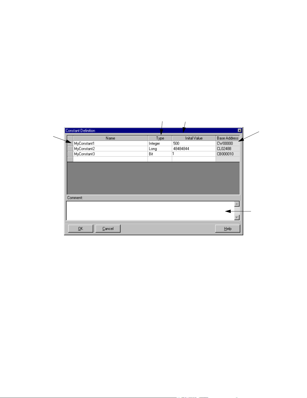
Constant Definition
Constants are added using the Constant Definition window that appears below. The
memory range for constants is 32,767 integers. If longs, floats, and bits are used, the
maximum number of constants is affected accordingly.
Accessibility
To access the constant definitions.
• From the Project Explorer > Data > Constants
• From the Main Menu > Project > Data > Constants
1
1. Name
The user-given field name of the constant.
2
3
4
5
2. Type
This field determines the potential magnitude of the constant.
3. Value
This field sets the value of the constant. Constants cannot be changed by the program
at run time.
4. Base Address
This field is a read only field indicating the register location of the constant in the
controller memory. This is provided for debugging with MotionWorks or accessing
data via Memobus serial communication.
29
Page 36

The Project Explorer MotionWorks+™
5. Comments
This field provides a location to document constant usage.
Network Definition
Network data are added using the Network Definition window that appears below.
Accessibility
To access the network definitions, select:
• From the Project Explorer > Data > Network
• From the Main Menu > Project > Data > Network
1
2
3
4
5
7
6
8
9
1. Name
The user-given name of the network data.
2. Node
This column only appears if Network Function is set to “master.” The cells in this
column contain a drop-down box that lists the remote I/O nodes configured.
3. Type
This field determines the potential magnitude of the data.
30
Page 37

MotionWorks+™ The Project Explorer
4. Initial Value
This field presets the value of the data when the power is turned on. If no initial value
is entered, the data is not initialized when the power is turned on (which is useful for
preserving data values when the power is cycled).1
5. Starting Word
The cells in this column contain a drop-down box. The contents are a list of valid
words starting at zero. The maximum value is derived from either of two places,
depending on the configuration of the controller, as follows:
• If the controller is configured as a network master, the Starting Word range is
defined by the System Properties > Remote I/O Block > Input/Output Word
properties.
• If the controller is configured as a network slave, the Starting Word range is defined
by the System Properties > Network Block > Input/Output Word properties.
6. Bit
This selection is only available if the Type is “input bit” or “output bit”. Select “0”
through “F” from the drop-down list. If a bit type variable is not defined, this cell
appears gray, and cannot be set. Also, under DeviceNet configuration, if an odd
number of bytes are defined, the drop-down list only shows “0-7” if the final “Starting
Word” is selected.
7. Base Address
This field is a read only field indicating the register location of the data in the
controller memory. This is provided for debugging with MotionWorks™ or accessing
data via Memobus serial communication. Base Address is determined by the information specified in the Node, Starting Word, and Bit columns.
8. HMI Checkbox
This field is used to set data to be written to the HMI export file.
31
Page 38

The Project Explorer MotionWorks+™
Allocation Wizard
If several network data of the same type are required, the Allocation Wizard can
automatically create data names based on user-provided input. The automaticallycreated names include the node name and I/O type.
1. Possible only when the battery option is installed to preserve RAM when power is OFF.
For example, the created names may appear as in the text box of the figure below.
2 3 4
1
1. Node
This drop-down box contains the node number and name of each slave as defined in
System Properties of the Configuration. If the controller is configured as a network
slave, the Node box is disabled.
2. Type
This field determines the potential magnitude of the data.
Data Type Minimum Maximum
bit 0 1
float
integer -32768 32767
long -2147483648 2147483647
-3.402832
e-38
3.402823
e38
3. Quantity
This entry is limited by the Network or Remote I/O configuration properties,
depending on whether the controller is configured as a master or a slave.
When a bit type is selected and the quantity is greater than the number of bits in a
word, allocation automatically proceeds to the next word in sequence. Note: for
remote I/O data, more than one data name can be assigned to the same memory
location.
4. Starting Word
32
Page 39

MotionWorks+™ The Project Explorer
This column contains a list of possible starting words. The list is created based on the
input/output properties in the configuration
I/O Definition
Digital and analog input/output names can be reviewed and edited on the window shown
below.
1
2
3
4
1. Name
he inputs/outputs are assigned default names by MotionWorks+™ when a project is
created. These names appear in the list shown below. The names can be changed to
any character string that more accurately describes their function.
2. Type
This field indicates whether the name refers to an individual input or output bit, or an
entire word, which contains up to 16 input or output bits. If the I/O is an analog type,
the 16-bit word contains the binary representation of the analog voltage.
3. Initial Value
his field only applies to outputs. Set the power ON logic state in this field. The
default output state is OFF.
5
6
33
Page 40

The Project Explorer MotionWorks+™
4. HMI Checkbox
This field is used to set data to be written to the HMI export file.
5. Cross Reference
This field retains the default I/O name assigned by MotionWorks+™ and displays the
register location of the I/O in the controller. This is provided for debugging with
MotionWorks™ or accessing data via Memobus serial communication.
6. Comments
This field provides a location for users to document I/O usage.
Table Definition
Table data is an array of values, all of which have the same name. They are accessed by
using the syntax “MOVE[i] = n”, where “i” is an integer or long, and “n” is a valid value
for the table. There are two table formats available - constant and dynamic. If a constant
table is defined (read only = true), the table data must come from a .cdd, .txt, .dat, or .csv
file. Constant table data cannot be modified by the program. If the table is configured as
a dynamic table (read only = false), the data can optionally be loaded from a file, or generated at run time with SET VARIABLE blocks. Note: Tables are zero based, and no bound-
1
2
3
4
5
6
7
8
ary checking is provided. Care must be taken by the programmer to remain within the
bounds of the table, or other data may get corrupted.
1. Table Name
The user-given name of the table.
34
Page 41

MotionWorks+™ The Project Explorer
2. Type
Select from “.cam”, “.txt”, “.dat”, “.csv”, or “Empty Table”. A CAM table is imported
from an *.cdd file and follows the cam tool format. A .csv file is an ASCII file with
data separated by commas. An empty table is either downloaded at run time or
generated within the MW+ program with SET VARIABLE blocks.
3. Data Type
This field determines the potential magnitude of each item in the table.
4. Read Only
This field determines whether items in the table can be changed by the program at run
time.
5. File Name
For Cam (.cdd) or .csv tables, select the file from which data is imported.
6. Entries
Select the maximum number of items the table can contain. If a file is imported, the
Entries property is automatically determined by the size of the file.
7. Base Address
This field is a read only field indicating the starting register location of the table in the
controller memory. This is provided for debugging with MotionWorks™ or accessing
data via Memobus serial communication.
8. HMI Checkbox
This field is used to set data to be written to the HMI export file.
35
Page 42
The Project Explorer MotionWorks+™
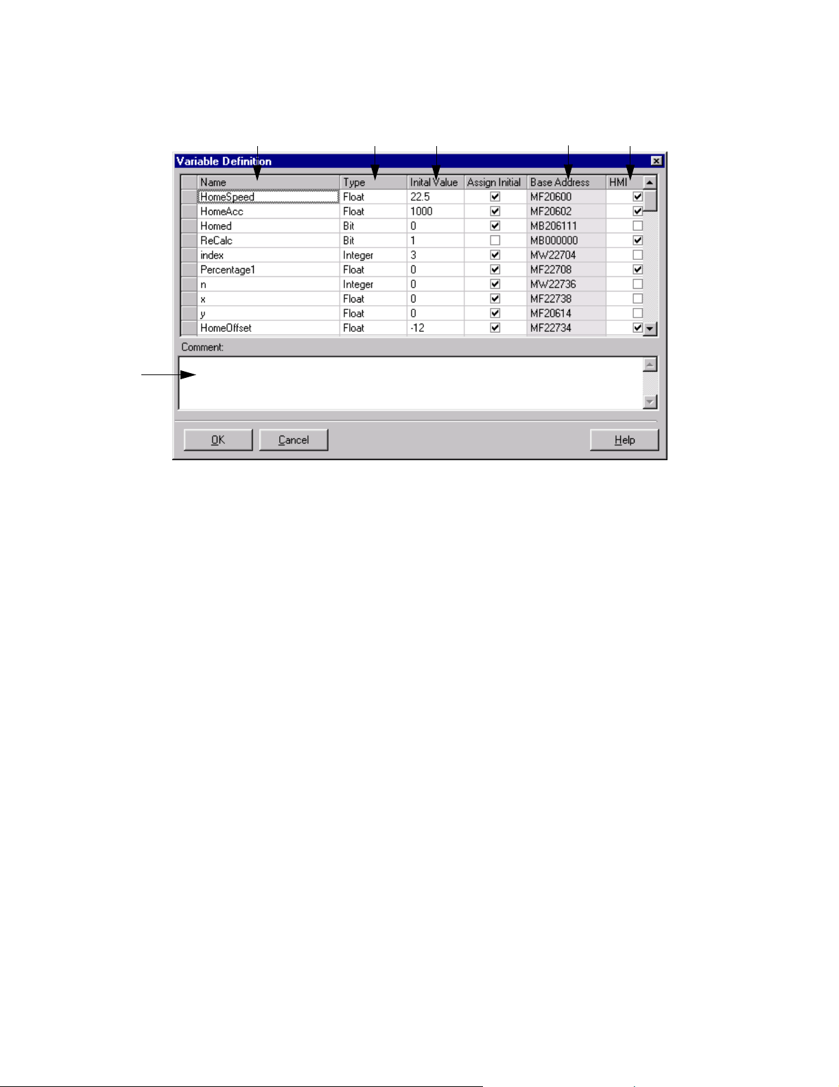
Variable Definition
6
1. Name
This field is the user-given name of the data.
1
2
3
4
5
2. Type
This field determines the potential magnitude of the data.
3. Initial Value
This field presets the value of the variable when the power is turned on. If no initial
value is entered, the data is not initialized when the power is turned on (which is useful
for preserving values when the power is cycled).
1
4. Base Address
This field is a read only field indicating the register location of the data in the
controller memory. This is provided for debugging with MotionWorks™ or accessing
data via Memobus serial communication.
Note: If a bit type variable is defined and checked as an HMI variable, the address of the
bit will be moved down to the region MB00000 ~ MB20470.
5. HMI checkbox
This field is used to set data to be written to the HMI export file.
6. Comments
This field permits users to document variable usage.
1. Possible only when the battery option is installed to preserve RAM when power is OFF.
36
Page 43

MotionWorks+™ The Project Explorer
System Variables
System variables are internal keywords which can be stored or accessed in expressions at
run time. The names of the system variables cannot be changed by the user.
37
Page 44

The Project Explorer MotionWorks+™
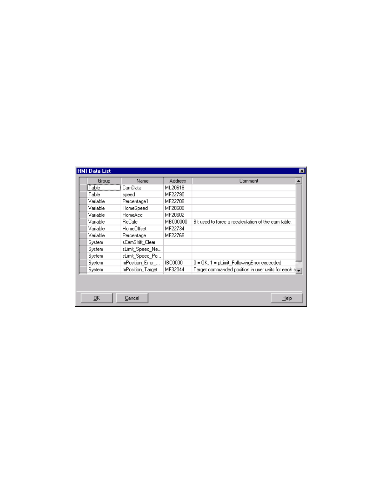
1.6.1 HMI Data
Accessibility
To access the HMI data, select:
• From the View Menu > HMI Data List
General
Each data item in the project can be identified as used in conjunction with a HumanMachine-Interface (HMI) by checking the box located next to each user variable or
system variable. The HMI data export will automatically occur each time the project is
saved.
Setting data for HMI Export
Simply check the box at the right side of the row.
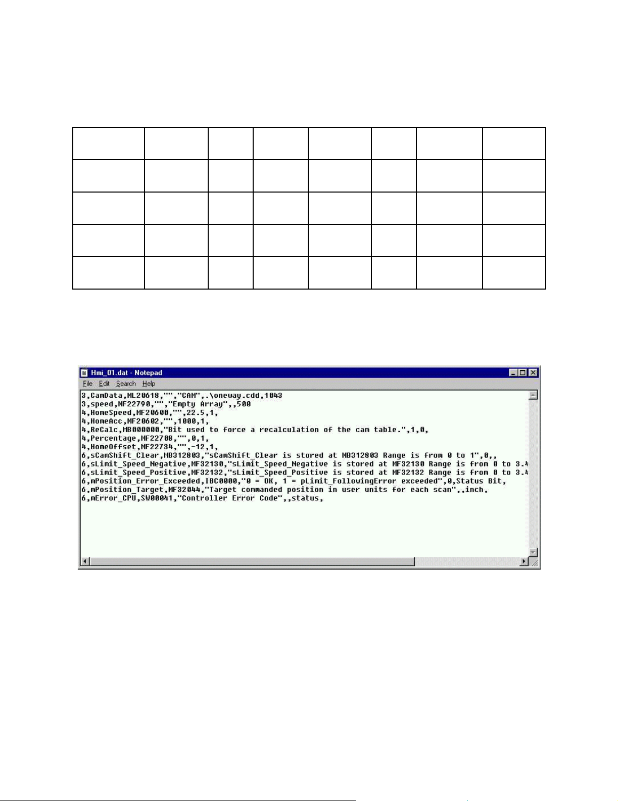
HMI Export File
Each data type excluding constants has a check box at the right of the line item that
can be used to identify project data as exportable to a comma separated value (CSV)
file. This file, (called HMI_xx.DAT) is automatically saved when the project is
saved. The following is a description of the file format.
38
Page 45
MotionWorks+™ The Project Explorer
Viewing HMI data
All data marked for HMI export are identified by the check mark. Alternatively, a
window is available to view all items marked for HMI export under the View menu.
Importing data is possible by reading a file with the same format that is exported. This
can be accomplished by right clicking on the Project Explorer’s Data Folder.
The data on this screen is for viewing purposes only, except that the user will be able to
remove items from the HMI data list by right clicking on one or several selected rows
and choosing “Remove from HMI list” from a sub menu. This has no effect on the data
in the project, other than to clear the checkmark on the corresponding data definition
window.
39
Page 46
The Project Explorer MotionWorks+™
File Data Format
The imported/exported CSV file will be of the following format:
(Network)
(Table)
(Variable)
(I/O)
(System)
Code=2 Name Address Comment Initial
Value
Code=3 Name Address Comment Table
Type
Code=4 Name Address Comment Initial
Value
Code=5 Name Address Comment Initial
Value
Code=6 Name Address Comment Initial
Value
Network
Node
FileName Entries
Starting
Word
40
Page 47
MotionWorks+™ The Project Explorer
Variable Mapping
If a bit type variable is set for HMI usage, it will be mapped within the range of
MB000000 through MB02047F. This restriction will be enforced because Memobus
can only write bits in the range of MB000000 through MB04096F. When Memobus
writes bits outside of this range, the entire word is written, not just the bit, so there is a
possibility of corrupted data.
Importing an HMI Data List
Accessibility
To import an HMI data list, select:
• From the Project Menu > Data >Import HMI
• From the Project Explorer > Right click on an item in the Data folder and select
“Import.”
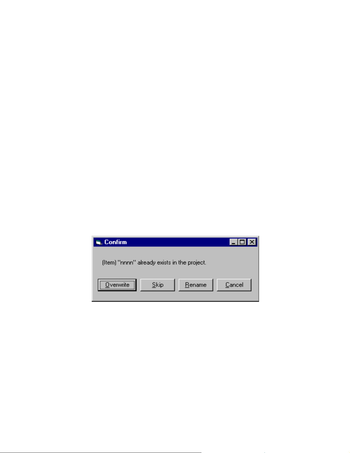
Import Method: If there are no variables, network, or tables in the project, the import
function will proceed without dialog for each type of item that has no existing entries. If
there are existing entries, the import will append to the list. If names already exist in the
current project, notification will be given to the user by the MW+ Importing Error dialog
box shown below.
41
Page 48

The Project Explorer MotionWorks+™
1.6.2 Import/Export Initiation
General
The import utility will determine what category each imported value falls in.
All Data Groups
Import will be initiated from Project>Data drop down menu or by right clicking on the
Data object in the Project Explorer.
Individual Data Group
Import will be initiated from Project>Data drop down menu which will expand to show
all data types when the user moves the mouse over “Data”, or by right clicking on the
specific Data object in the Project Explorer.
Name and address checking will be done on the full data area (Constants, Tables,
Network, Variables, I/O, System Variables, System Parameters, System Ladder
Registers and System Registers). The name and the address must be unique across the
full data area, with the exception of overlapping addresses in the Network data area.
The register range for MW+ system registers (MW20000 ~ MW20599) and the register
range for system ladder registers (MW30000 ~ MW32767) are reserved so that user
variables are not allowed in these areas; however, the user will be allowed to import
values for the system ladder type variables.
Constants
The name, initial value, address, and comment will be imported. The type will be
derived from the address.
Network
The name, node, initial value (if present), address, starting word, and comment will be
imported. The type and bit will be derived from the address.
If configuration for the node is completed and configuration for that node matches
configuration from the existing project, import of the network will proceed.
If the configuration for that node does not exist or does not match the configuration from
the existing project, a message box will appear stating “The data for node x cannot be
imported, because the configuration of node x is missing or does not match.” The user
can choose to cancel, skip node, or import the configuration.
1. If the name is unused, the import of that item will proceed without dialog.
42
Page 49

MotionWorks+™ The Project Explorer
2. If the imported name and address exactly match an item in the database, the value
and the comment will be imported.
3. If the imported name matches an item in the database but the address does not, the
user will be shown the following grid with the existing name and address and the
importing name and address.
A message will be displayed stating the conflict, and the user will be allowed to
choose from the following options:
Rename Existing
This button will present the user with a text box where a new name for the
existing item can be typed.
Rename Imported
This button will present the user with a text box where a new name for the
importing item can be typed.
Skip
Skips importation of this network.
Overwrite
Imports the table and removes the existing item(s).
Cancel
The import operation is canceled leaving the data area unchanged.
1. Address overlap will be allowed as currently implemented for the network data area.
43
Page 50

The Project Explorer MotionWorks+™
Table s
The name, filename (if present), address, table type, number of entries, and comment
will be imported. The type and read only status will be derived from the address. If the
filename is present the file will be copied to the project directory, and the data will be
transferred with the project.
1. If the name and the full address range is unused the import of that item will proceed
without dialog. The full address range check will look for bits, words, longs, and
floats that overlap the imported address range.
2. If the imported name and address exactly match an item in the database, the filename
(if present), and the comment will be imported.
3. If the imported name matches an item in the database but the address range does not,
the user will be shown the following grid with the existing name, number of entries
(if table type) and address and the importing name and address range.
Name Entries Address Range
Imported Position 10 MW2001 ~
MW2010
Existing Position N/A MB1001
A message will be displayed stating the conflict, and the user will be allowed to choose
the following options:
Rename Existing
This button will present the user with a text box where a new name for the
existing table can be typed.
Rename Imported
This button will present the user with a text box where a new name for the
importing table can be typed.
Skip
Skips importation of this table.
Overwrite
Imports the table and removes the existing item(s).
Cancel
The entire import operation will be canceled leaving the data area unchanged.
44
Page 51

MotionWorks+™ The Project Explorer
1. If the imported address matches any existing item within the address range, the following grid will be displayed with all of the existing name(s) and address(s) and the
importing name and address.
Name Entries Address
Imported
Existing
Existing
MyTable1 100 MW1000 ~ MW
1099
MyTable2 10 MW1000 ~ MW
1009
MyWord1 N/A MW1010
A message will be displayed stating the conflict, and the user will be allowed to choose
the following options:
Re-address Existing
This button will readdress all existing data that is in the imported table space.
MW+ will preserve the order of the existing data.
Readdress Imported
This button will re-address the imported table. MW+ will find a contiguous area
of memory for the table.
Skip
Skips importation of this table.
Overwrite
Imports the table and removes the existing item(s).
Cancel
The import operation is canceled leaving the data area unchanged.
Variables
The name, initial value (if present), address, and comment will be imported. The type
will be derived from the address.
1. If the name and the full address range is unused the import of that variable will proceed without dialog. The full address range check will look for bits, words, longs,
and floats that overlap the imported address.
2. If the imported name and address exactly match a variable in the database, the value
and the comment will be imported.
45
Page 52

The Project Explorer MotionWorks+™
3. If the imported name matches an item in the database but the address does not, the
user will be shown the following grid with the existing name and address and the
importing name and address.
Name Address
Imported MyBit1 MB2001
Existing MyBit1 MB1001
A message will be displayed stating the conflict, and the user will be allowed to choose
the following options:
Rename Existing
This button will present the user with a text box where a new name for the
existing item can be typed.
Rename Imported
This button will present the user with a text box where a new name for the
imported variable can be typed.
Skip
Skips importation of this variable.
Overwrite
Imports the variable and removes the existing item.
Cancel
The entire import operation will be canceled leaving the data area unchanged.
1. If the importing address matches any existing item within the address range, the following grid will be displayed with all of the existing name(s) and address(s) and the
importing name and address.
Name Address
Imported MWord1 MW100
Existing MyBit1 MB1001
Existing MyBit1 MB1002
A message will be displayed stating the conflict, and the user will be allowed to
choose the following options:
46
Page 53

MotionWorks+™ The Project Explorer
Readdress Existing
This button will readdress all existing data that is in the importing address space.
MW+ will preserve the order of the existing variables, so it cannot simply insert
the existing variables back into the list.
Readdress Imported
This button will readdress the imported variable.
Skip
Skips importation of this variable.
Overwrite
Imports the variable and removes the existing item.
Cancel
The entire import operation will be canceled leaving the data area unchanged.
I/O
The name, initial value (if present), address, and comment will be imported. The type
will be derived from the address.
System Variables
If a register value matches a system variable, the Name will be compared. If the names
do not match, a warning is issued to the user that a non-system variable existed in a
location reserved by MW+ for system variables.
47
Page 54

The Project Explorer MotionWorks+™
Monitoring
All monitoring functions are available only after going online with the exception of
Scope. There are 4 monitoring views available: Data, I/O, and Program and Scope.
I/O Monitoring
Accessibility
To monitor the I/O, select:
• From the Project Explorer > Monitoring > I/O
• From the Main menu > Project > Monitoring > I/O
48
Page 55

MotionWorks+™ The Project Explorer
Program Monitoring
Accessibility
To monitor the program, select:
• From the Project Explorer > Monitoring > Programs
• From the Main Menu > Project > Monitoring > Programs
2
3
1
1. Program
Select the checkbox in this column to enable monitoring for any program.
2. Name
This column displays the program or subroutine name currently active.
3. Block No.
This column displays the current block being executed and further indicates whether
the program is running.
Monitoring Data
Any data can be monitored while online with the controller via the windows shown
below. Read/Write data can be changed on-the-fly using the Watch window. A list of
data selected for monitoring is saved so that the same data set can be monitored again
during future sessions with the same project.
Accessibility
To access the Watch window, select:
• From the Main Menu > Project > Monitoring > Data
49
Page 56
The Project Explorer MotionWorks+™
• From the Project Explorer > Monitoring > Data
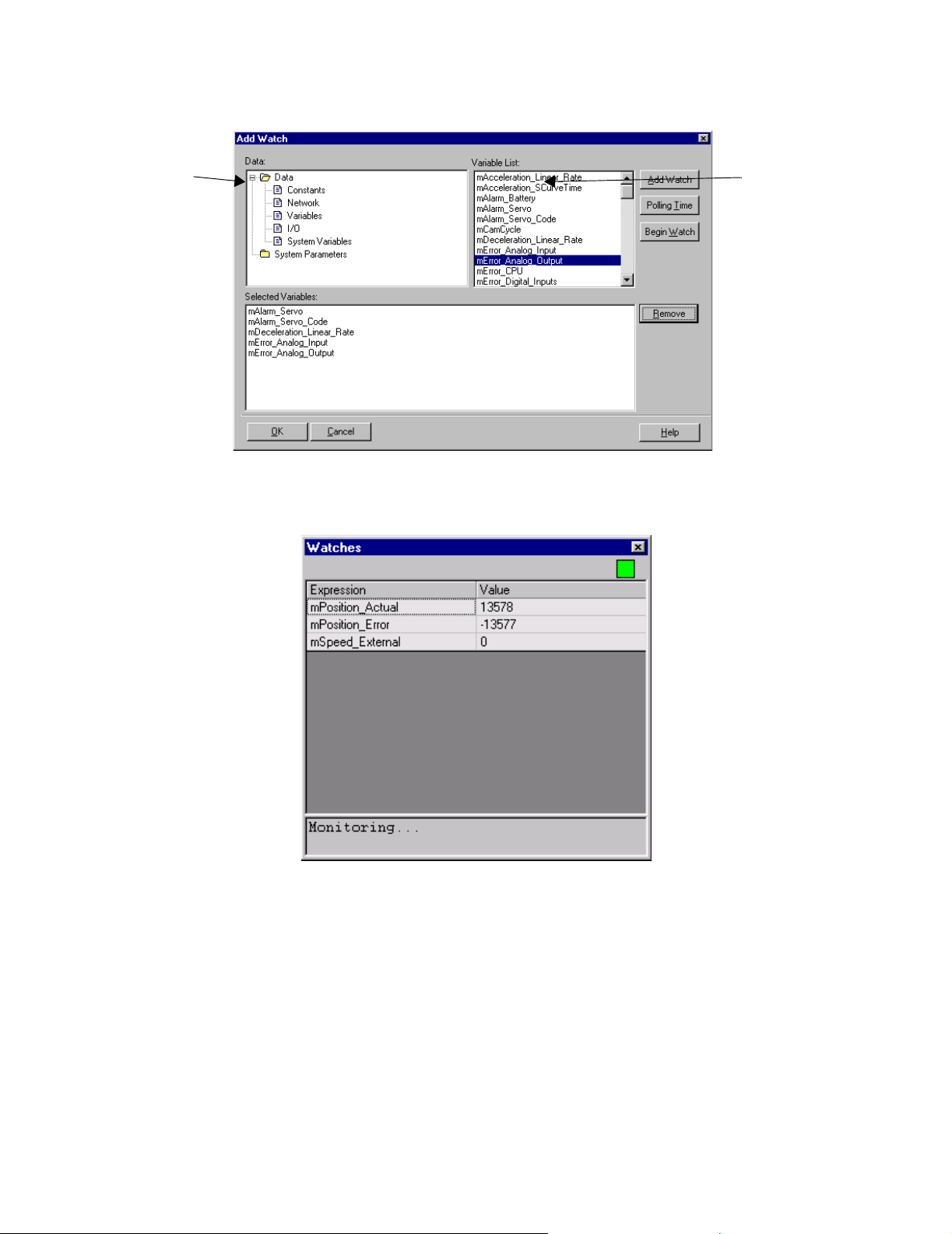
1
2
1. Open folders from the Data text box.
2. Double-click on items in the Variable List to add them to the Watch window.
While viewing the watch window, data can be modified by typing a new value in the
right column. Variable updates occur as soon as the Enter key is pressed or the cell
loses focus. While editing data, the Variable Watch window does not update. This is
indicated by the status light in the upper right corner of the window.
50
Page 57
MotionWorks+™ Scope
1.7 Scope
Accessibility
To view the scope display, select
• From the Main Menu > Project > Monitoring > Scope
• From the Project Explorer > Monitoring > Scope
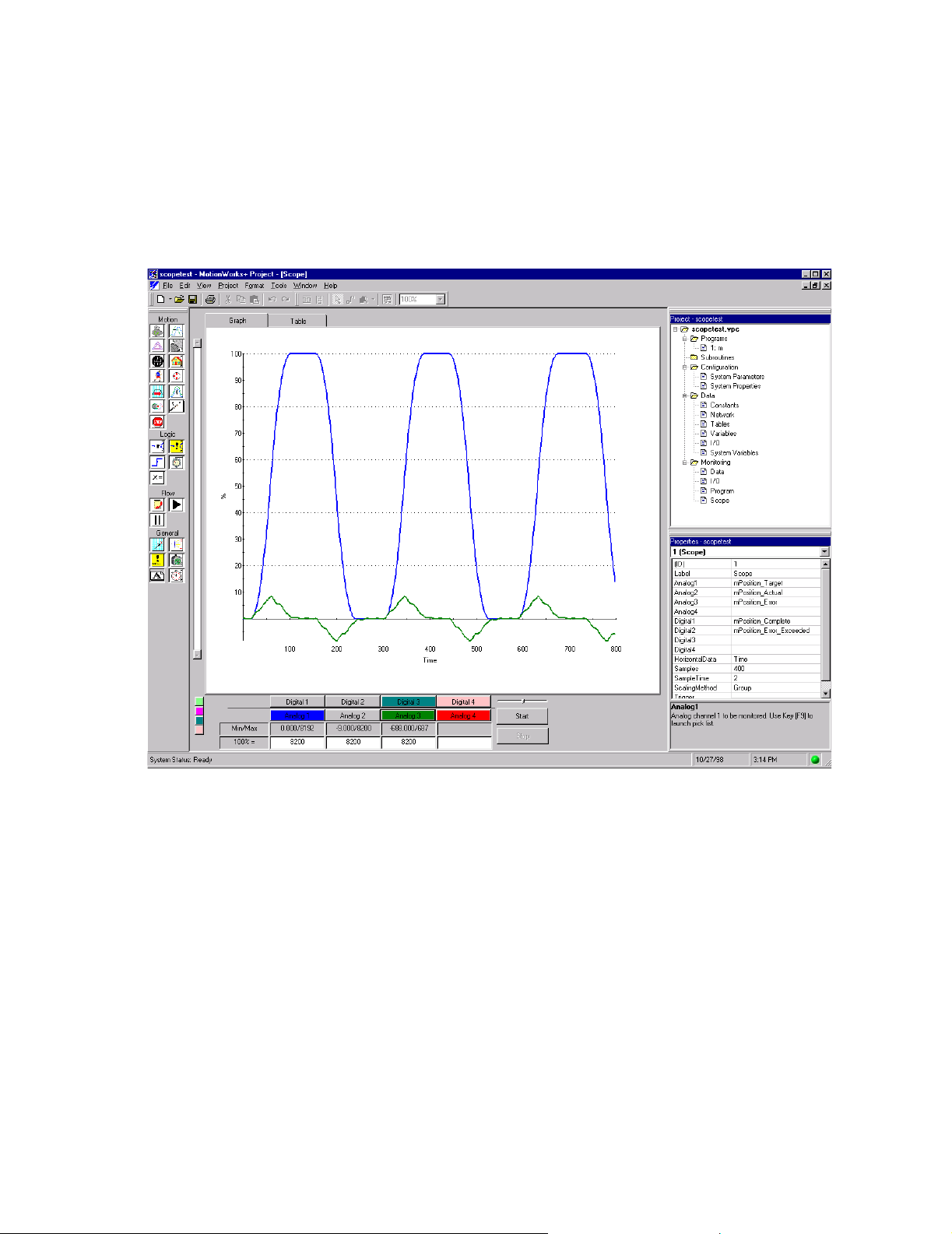
The Scope displays recorded data. Choose data to be recorded and duration in the
properties window. The Scope has the capability to display up to eight separate data
elements.
There are tabs at the top of the graph that allow the user to switch between viewing data
graphically or in a table.
The following are the properties for the Scope. These properties are applied when the
user clicks on the start button.
51
Page 58

Scope MotionWorks+™
Properties
Property Default
Analog1 Nothing N/A N/A Any Data
Analog2 Nothing N/A N/A Any Data
Analog3 Nothing N/A N/A Any Data
Analog4 Nothing N/A N/A Any Data
Digital1 Nothing N/A N/A Any Bit Data
Digital2 Nothing N/A N/A Any Bit Data
Digital3 Nothing N/A N/A Any Bit Data
Digital4 Nothing N/A N/A Any Bit Data
HorizontalData
Samples 1000 10 32767 Samples / depend
SampleTime 1 0.5 5000 mSec
ScalingMethod
Time Analog1 Analog4 N/A
Custom Custom None Group, Individual,
Minimum
Value
Maximum
Value
Notes
on data types
None
Trigger Nothing N/A N/A Expression builder
Analog 1~4
Select the data that will be captured for display on this channel. To use the
expression builder, press F9.
52
Page 59

MotionWorks+™ Scope
Digital 1~4
Select the digital data that will be captured for display on this channel. When a
digital signal is displayed on the graph, it will occupy 20% of the graph height.
To use the expression builder, press F9.
HorizontalData
Normally the horizontal time scale is “Time.” It is possible to select any analog
channel data as the horizontal time scale. If only one analog channel is defined
and no digital channels are defined, the only choice is “Time.”
Samples
Specify number of points to be recorded for each channel. The maximum
number of storage words is 4096. MW+ will determine if there is enough
memory to perform the scope function based on the number of channels selected
and notify the user if there is not enough memory.
SampleTime
This is the number of milliseconds between samples. The sample time cannot be
less than the High scan setting in the MP940 system properties.
ScalingMethod
Specify how analog data is displayed on the graph. MW+ will determine the
upper and lower bounds of the Y axis and the “100% = ” number for each
channel based on the setting of this property. For all cases below, there will
always be either a 100% or a –100% boundary, or both.
53
Page 60

Scope MotionWorks+™
When this property is set to “group,” each channel will be scaled to the same
“100% =” number. Scaling is derived from the channel with the largest absolute
min/max value.
When this property is set to “individual”, each channel will be scaled to occupy
most of the graph. MW+ will calculate the “100% =” number for each channel
to obtain the best possible fit.
When this property is set to “none”, scale values will be used from the previous
Scope, and the vertical scale will be:
if all channel data are positive: 100 to 0%
if all channel data are negative:0 to -100%
else: 100 to -100%.
The vertical axis is always scaled in percent. Each channel can have a different
scale such that 100% for analog channel #1 can be different from analog channel
#2.
Trigger
The trigger is optional. If the user enters a trigger expression and clicks on start,
the Scope will not begin until the expression is true. If no trigger is entered, the
Scope will begin immediately after clicking Start.
To start Scoping, select data for at least one channel and click on the Start
button. The Scope window will display the following text messages in a text box
until data is ready to be displayed:
If a trigger is selected, and triggering has not begun
“Waiting for trigger.”
If recording data then
"Recording data."
If uploading data
"Uploading data"
54
Page 61

MotionWorks+™ Scope
Notes about Triggering:
This is the basic format of a trigger: [data] [OP] [Constant]
Example of a trigger: mSpeed_Main >= 200
The following operators may be used:
++
!=
<
>
<>
<=
=>
true
false
If the [Data] is a bit, then the [OP] must be “=”.
If the [Data] is a bit, the the [Constant] must be “ON or “OFF”.
If the [Data] is an integer, then the [Constant] must be an integer.
If the [Data] is a float, then the [Constant] can be integer, float, or in exponential
form.
Analog Channel Controls
To switch the graphed data on and off, click the Channel Display buttons. The Channel
Display buttons are the same color as the graph line. When the mouse is held over the
Channel Display button, a tool tip will display the data name.
The minimum and maximum data value is displayed for each channel.
Each channel indicates 100% value in data units. If “Scaling Method” is “none,” the
previous value is retained. If it is “group” or “individual,” the value is calculated by
MW+ to maximize the information on the screen. Adjust this value to customize the
view.
Use the horizontal slider to determine the current value of each channel at any point
along the graph. When the mouse button is held down over the horizontal slider, the
“Min/Max” field label will change to “Current value.” A vertical dashed line appears
on the graph at the slider location, and the current value is displayed in the Current Value
field. When the button is released, the “Current Value” field will revert to “Min/Max.”
55
Page 62

Scope MotionWorks+™
Digital Channel Controls
To switch digital channels ON or OFF, use the “Digital Enable” buttons at the bottom of
the Scope window. The channel display buttons are the same color as the digital graph
line. When the mouse is held over the channel display button, the data name is
displayed.
A vertical slider controls the vertical placement of the digital channels. Only one of the
four vertical slider control buttons can be active at any time. The four buttons are color
coded with the digital data colors. When the vertical slider control button for digital
channel one is active, the scroll bar indicator will be located at the zero level for digital
channel one data. It is possible to change the zero level for each digital channel by
moving the slider. This can be used to separate digital channels for easier viewing.
Graph Controls
It is possible to zoom on any portion of the graph. Enter a specific zoom percentage, Fit
in Window, or zoom on a specific range (window). To zoom into a specific range on the
graph, depress the left mouse button and drag over the graph until the desired range is
highlighted. When the button is released, the graph will display the zoomed range.
When the entire graph does not fit in the window, vertical and/or horizontal scroll bars
will appear, making it possible to access the non-displayed areas of the graph.
It is possible to display data in a graph or table by selecting the graph or table tab.
It is possible to import, export, or save recorded data by selecting items from the right
click menu while the mouse is over the graph or chart.
56
Page 63

MotionWorks+™ Scope
Scope Examples
There are two colored graph lines shown in the example below:
The darker graph line indicates Analog 1.
The lighter graph line indicates Analog 2.
57
Page 64

The Block Toolbar MotionWorks+™
1.8 The Block Toolbar
The block toolbar contains all the programming icons. The toolbar can either float or dock to the left or top of the screen. The
blocks are visually grouped by a dividing line on the toolbar.
There are two icon sets available. The one shown on the left is
the YEA standard. The one on the right is the YEC standard.
Accessibility (Tool bar usage)
• From the Main Menu > View > Toolbars > Block
Accessibility (Graphic selection)
• From the Main Menu > Tools > Options > Block
Graphics
58
Page 65
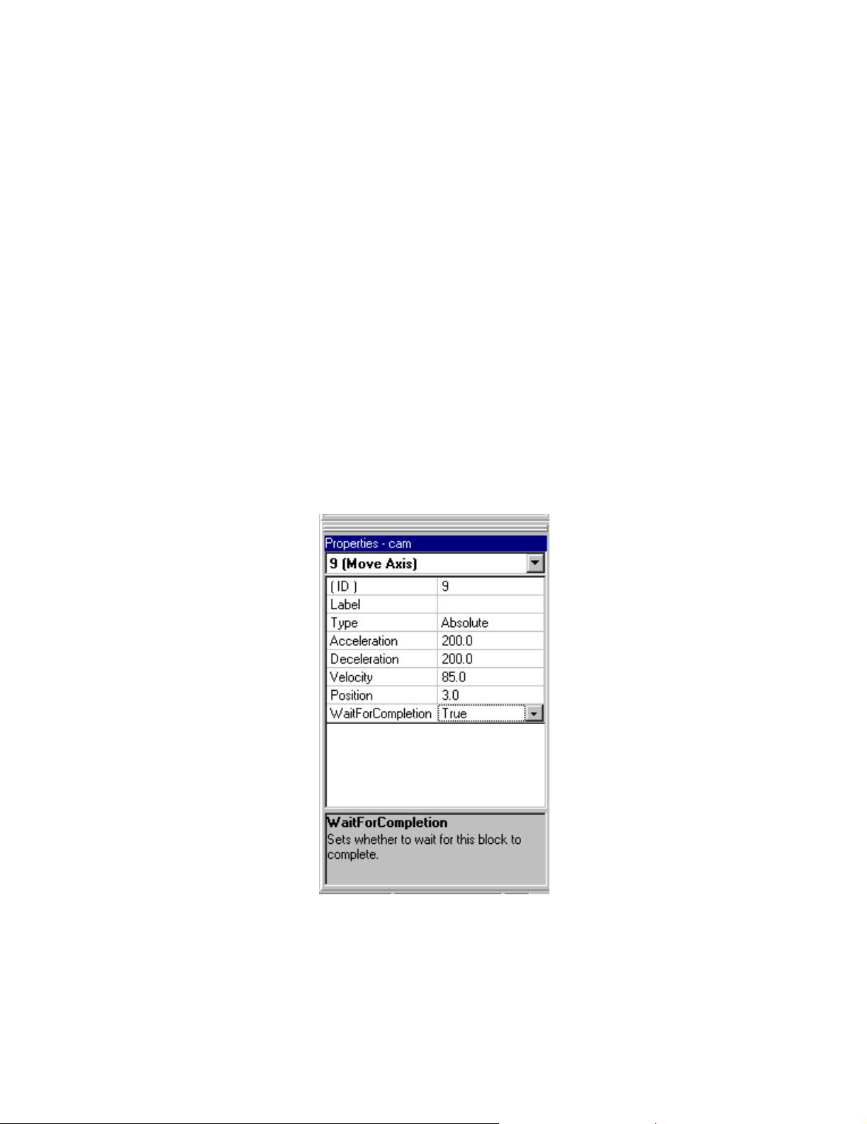
MotionWorks+™ The Properties Window
1.9 The Properties Window
All the details for each block are entered and edited in the Properties window. This
window can be dragged, resized, docked, and undocked. Properties change based on the
item/block selected. The Properties window has a Help text box that describes each
property. If no icon is selected, the properties are shown for the current program or
subroutine.
Accessibility
To access the Properties window, select:
• From the Main Menu > View > Properties
• From any block or configuration item > right-click > Properties
• If the Properties window is closed, double-click on an icon to re-display
The Properties window can be closed, but a right click on an icon allows this window to
re-appear. In many cases, the Expression Builder is available when double-clicking on
a property. This allows selection of data and the creation of formulas from organized
lists.
59
Page 66

The Program Window MotionWorks+™
1.10 The Program Window
The Program window is the location at which all the files in the project are displayed
when opened. There are two types of program windows that appear. The first type is
either a program or subroutine. The second type is a form that contains data from
monitoring, debug, parameter setup, etc.
Program Window Behavior
• Program Positioning
The programming area is generally referred to as the “canvas.” Canvas positioning
is virtually unlimited, as the scroll bars allow for infinite scrolling. The Home key
puts the START block at the center of the program window. The End key puts the
END block at the center of the program window. The zoom range of the program
window is between 10% ~ 400%.
• Block Placement
The program window has a snap to grid feature that allows blocks to be placed uniformly. Snap to grid is the default setting, and is global for all programs and subroutines in the project. The default grid size is equivalent to one block. The minimum
grid size is ½ block. The maximum grid size is 5 times one block. Blocks cannot be
placed one on top of the other.
• Block Editing
The Cut/Paste/Copy functions conform to Windows standards. The selected block
has a highlighted background. To select multiple blocks, hold the Ctrl key down
while clicking on additional blocks. This allows repositioning of a group of blocks.
• Block Connections
Connect blocks by first selecting the connection mode function from the programming tool bar. The mouse pointer changes to a diagonal line. Click and hold
the left mouse button down while near the output port of a block. Move the cursor
near the input port of another block to extend the line, then release the mouse button.
The connection lines automatically position themselves horizontally or vertically on
the canvas. Arrows show the program flow from one block to another. Lines
conform to the Windows standards for editing, i.e., when selected, they are highlighted and handles appear for resizing and moving. When blocks with connections
are repositioned, only the connection line from the moved block to the first handle
repositions itself. Reposition the entire connection path manually if necessary.
60
Page 67

MotionWorks+™ The Program Window
• Block Appearance
The bitmaps of some blocks change depending on the property settings for the block.
CAM GEAR
Enabled = True Enabled = False
LATCH SERVO
Enabled = True Enabled = False Enabled = True Enabled = False
INPUT
Enabled = True
Enabled = False
11 12 13 14
Rising edge Falling edge Logic one Logic zero
61
Page 68
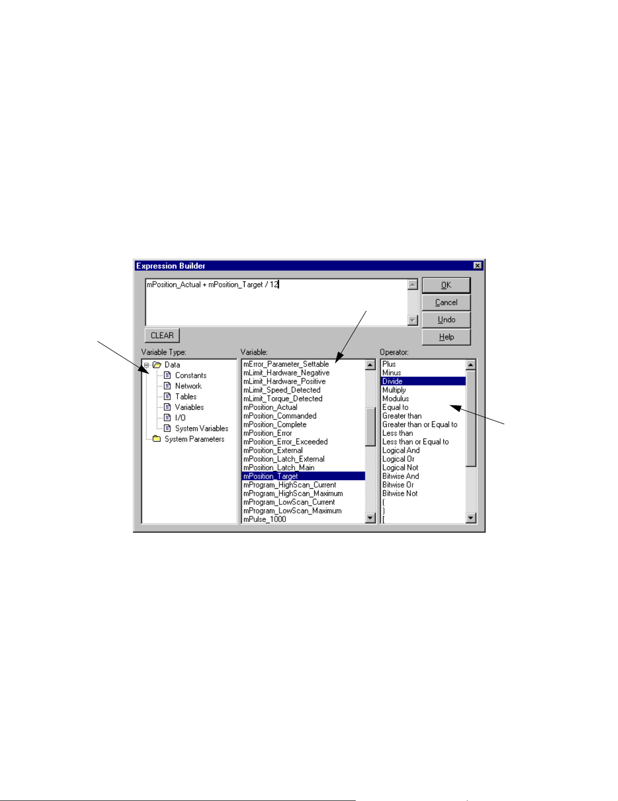
Expression Builder MotionWorks+™
1.11 Expression Builder
The Expression Builder is useful when generating complex calculations. The
Expression Builder is available when editing properties that can be updated at run time.
For example, the properties of the SET VARIABLE, MOVE AXIS, or CHANGE
DYNAMICS blocks are designed to be updated as the calculation variables change.
Additionally, logical expressions can be created for blocks such as IF EVENT, and IF
FAULT.
Accessibility
• Double-click on any block property that accepts an expression.
2
1
1. Variable Type
Select Constants, Network, Tables, Variables, I/O, or System.
2. Variable
Shows the list of data from the selected folder in the Variable Type window.
3
3. Operator
Shows all the available math functions. Select from the list by double-clicking; the
selected operator is then inserted at the cursor location in the expression.
62
Page 69

MotionWorks+™ Expression Builder
Creating Expressions
Double-click on the folders in the Variable Type window. Select an item from the
Variable window. The item is inserted at the cursor position.
For the purpose of explanation of the operators, assume the following:.
Variable Name Type Value
mPositon_Complete Bit 1
mSpeed_Main Float -36.274
mState_Latch_Main Bit 1
Mytable[Var2] Long 10000
Var1 Integer 100
Var2 Integer 10
Var3 Integer 75
Var4 Integer 10
Var5 Bit 1
Var6 Bit 0
Var7 Integer 85 (0x55)
Var8 Integer 170 (0xAA)
Var9 Float 0.1666667
Operator Symbol Example Expression Result
Plus + Var1 + Var2 110
Minus - Var1 - Var2 90
Multiply * Var1 x Var2 1000
Divide / Var1 / Var2 10
Modulus % Var3 % 4 3
Equal To == mPosition_Complete==Var5 1
Greater Than > Var1 > Var2 1
Greater Than or Equal to >= Var2 >= Var3 0
Less Than < Var1 < Var3 0
Less Than or Equal to <= Var2 <= Var4 1
Logical And && Var5&&mPosition_Complete 1
Logical Or | | Var5||Var6 1
Logical Not != mState_Main_Latch != Var6 1
Bitwise And & Var7 & Var8 0
Bitwise Or | Var7 | Var8 255 (OxFF)
Bitwise Not ! — —
( ) ( ) (Var1+Var2) / Var3 11
63
Page 70

Expression Builder MotionWorks+™
Operator Symbol Example Expression Result
[ ] [ MyTable[Var2] 10000
sin sin sin(Var9*180)*4096.0 2048
cos cos cos(0) 1
tan tan tan(45) 1
arctan acrtan artan(1) 45
Square Root sqrt sqrt(9) 3
Absolute Value abs abs(mSpeed_Main) 36.274
True true Var5==true 1
False false Var5==false 0
Note: If a floating point result is expected, at least one of the terms in the calculation
must contain a floating point value. This is true even if the terms are all hard coded.
Example:
ACCEL = 1000 (integer)
VELOCITY = 180 (integer)
Calculation:
Answer = sqrt (ACCEL/VELOCITY)
The above calculation does not produce accurate results because none of the terms are
floating points. The answer should be 2.35702, but is reported as 406.
One solution is to multiply the expression by 1.0. Another solution appears on the
following page.
Example:
ACCEL = 100.0 (floating point)
VELOCITY = 180 (integer)
Calculations:
Answer = sqrt (ACCEL/VELOCITY) or
Answer = sqrt (ACCEL/180.0) will produce the correct answer: 2.35702.
64
Page 71

MotionWorks+™ Cross Reference
More Example Expressions
Expression Description
JogFwd || JogRev Assumes both variables are bit type. This is a bool-
ean expression that evaluates to true if JogFwd is
true OR JogRev is true.
Start && !Fault Assumes both variables are bit type. This is a bool-
ean expression that evaluates to true only if Start is
true AND Fault is NOT true.
Positions[(Local_Input_Bank
& 30)/2]
Assumes Positions is a table and the calculation
inside brackets designates pointers for the index in
the table. It looks at bits 1, 2, 3, and 4 and masks the
rest of the byte by ANDing it with 30 decimal ($1E
hex). After masking, the data is shifted over by dividing by 2. The expression results in a value between
0 and 15.
1.12 Cross Reference
Accessibility
To view the cross-references, select:
• From the Main Menu > View > Cross Reference
The Cross Reference feature allows searching for all occurrences of a variable, phrase,
word, or expression. Double clicking on any cell in the row will display the instance.
The drop down box shown on the form will allow the user to search for items in 3 ways:
1. Type the phrase, name, or keyword to search.
2. Select from items in the dropdown list that contains the last 10 searches. This information is stored with each project.
3. Click on the Select button and pick an item from the expression builder.
65
Page 72
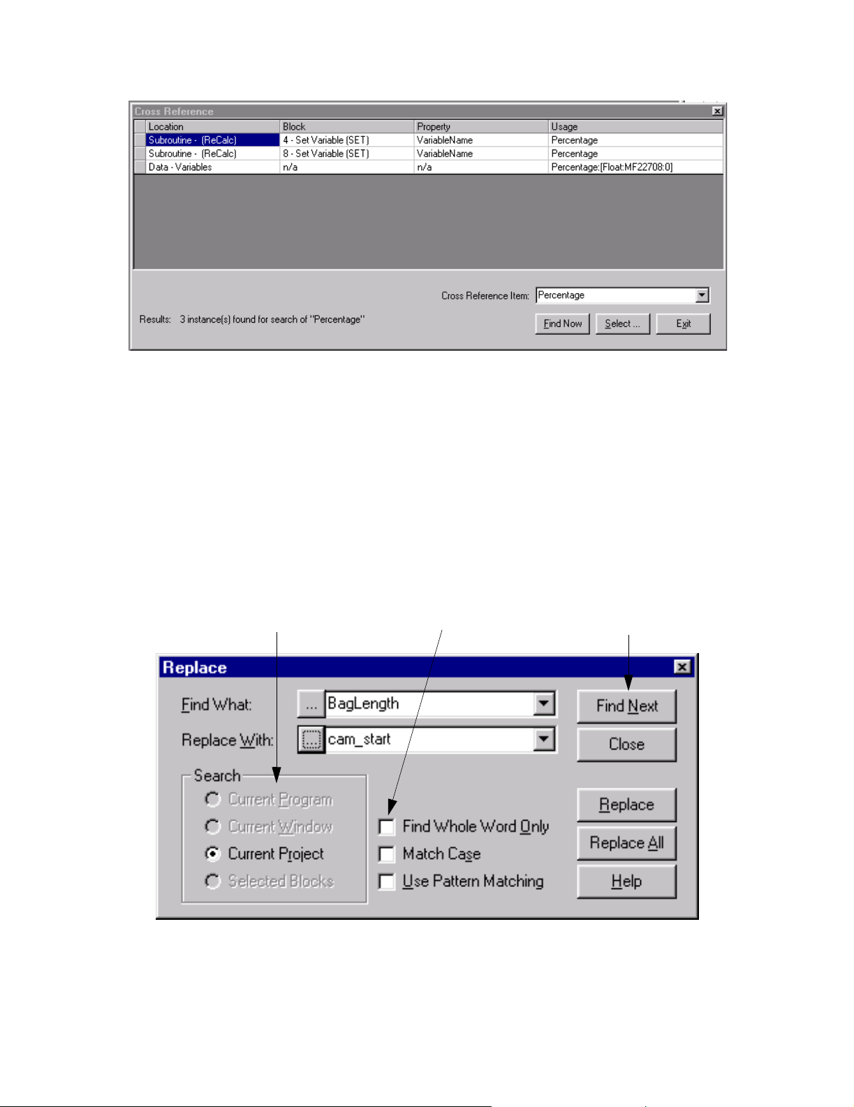
Search and Replace MotionWorks+™
1.13 Search and Replace
Accessibility
To access the search/replace dialog, select:
• From the Main Menu > Edit > Replace
The Search and Replace feature allows for locating words or terms that are already in the
program and replacing them with new terminology. Specific functions, i.e.; the Search
box (1), check boxes (2), and information tabs (3) make it easier to accomplish this task.
1
2
3
66
Page 73

MotionWorks+™ Connecting To The Controller
1.14 Connecting To The Controller
Online/Offline
Communication is established between MotionWorks+™ and the MP940 by going
online. The status bar on the lower left corner of the screen displays a message
indicating the connection status. Also, there is a green or black dot on the lower right
portion of the screen to indicate the connection status.
Accessibility
To go online, select:
• From the Main Menu > Tools > Online
• Hot Key: F6
Communication Settings
This section explains how to set communication between MotionWorks+™ and the
controller. When the installation is complete, the communication settings are set to the
default values, as follows: 19.2kbps; data bits: 8bit; parity: even; stop bits: 1Stop bit.
Launching the Communication Process
The Communication Process is a separate application that launches when attempting to
go online with the controller. It is a program that coordinates communication between
applications such as MotionWorks+™ and MP-series controllers. The Communication
Process is visible in the Task Manager. Double-click on it to view and edit the settings
67
Page 74
Connecting To The Controller MotionWorks+™
MotionWorks+™
Communication Process
Application X
CimScope
MP940
68
Page 75

MotionWorks+™ Connecting To The Controller
Setting the Communication Port
The main screen of the communication process is shown below. Either double-click the
logical port number, or select a logical port number in the Logical PT column, then
select Setting (E) from the File menu.
The Logical Port Setting window is displayed, as in the figure below. Select the port
type in the Port Kind box, then select Detail.
69
Page 76
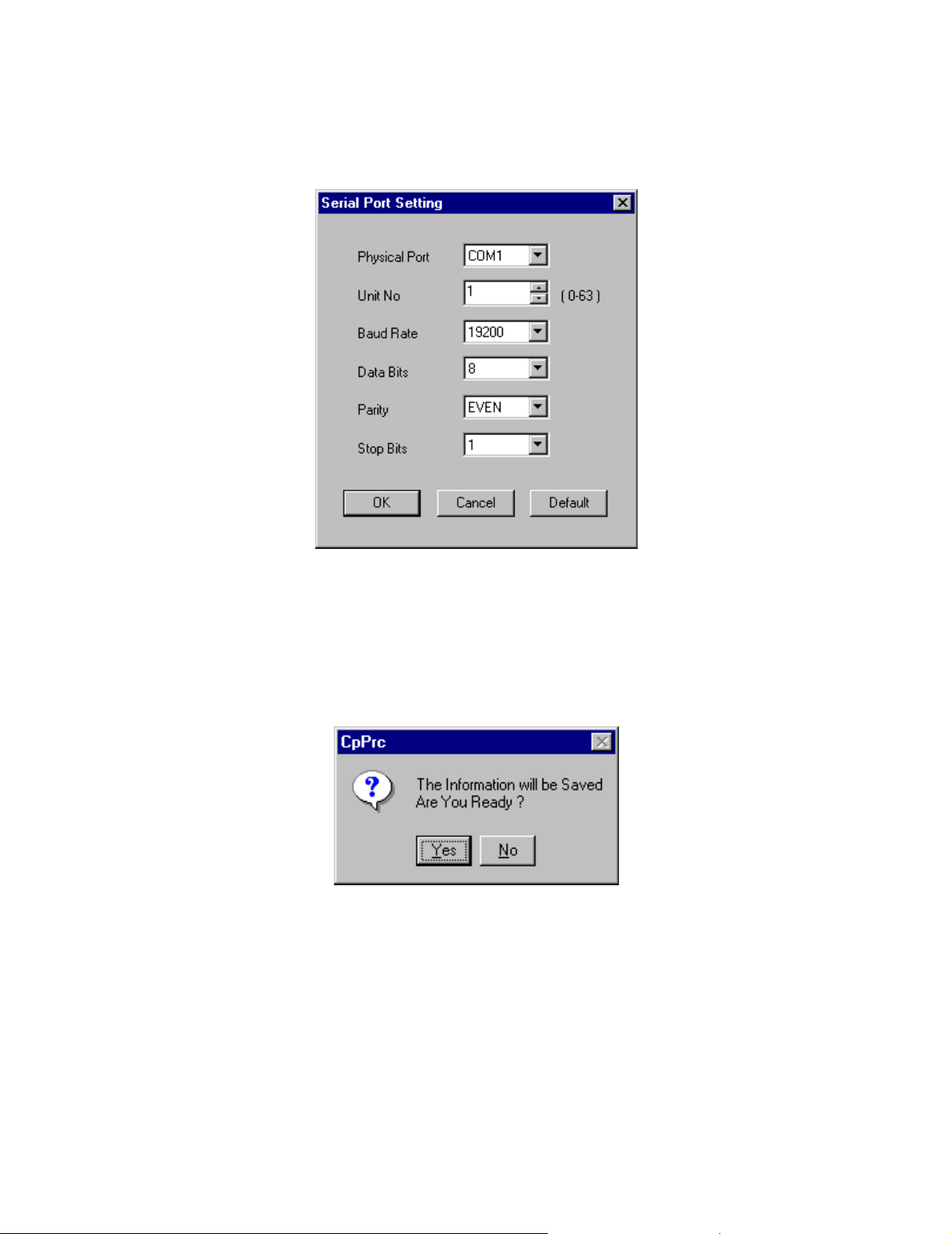
Connecting To The Controller MotionWorks+™
When Detail is selected, the following window is displayed. Set the parameters of the
serial port.
Saving Communication Port Setting Values
Select File > Save, and a confirmation message window appears. Choose the Ye s
button to save the information.
The Communication Process provides a link between MotionWorks+™ and the
controller. Do not close this program; minimize the Communication Process when the
settings are complete.
70
Page 77

MotionWorks+™ Compiling A Program
1.15 Compiling A Program
Compiling a program converts the block connections and properties into a format usable
by the motion controller.
Accessibility
To compile a program, select:
• From the Main Menu > Tools > Compile
• Hot Key: F5
Compiling Errors
If a compiling error has occurred, a window appears with a description of all errors
found. Double-click on the error to go to the property. The message box identifies the
following information:
1. Program name
2. Block number
3. Property
4. Error description
71
Page 78

Downloading a Project MotionWorks+™
1.16 Downloading a Project
Accessibility
To download a project, select:
• From the Main Menu > Tools > Download
• Hot Key: Shift+F5
MotionWorks+™ must be online with a controller before downloading. If the controller
is running, a message box appears that requests permission to stop the controller prior to
downloading. The controller must be stopped for a download to occur. This halts
program execution and disables the servo.
The download tool will automatically transfer only System Property modules and
programs changed since the last download. Full Compile & Download will force MW+
to download all System Property modules and programs.
After downloading, a message box appears requesting permission to restart the
controller. The project is now residing in SRAM, the battery backed memory. This
memory is retained by a super capacitor during power OFF for several hours without a
battery. If no battery is present, the project must be saved in flash memory for
permanent storage. See “Saving a Project to Flash” on the next page.
72
Page 79

MotionWorks+™ Saving a Project to Flash
1.17 Saving a Project to Flash
Accessibility
To save a project to the flash memory, select:
• From the Main Menu > Tools > Controller > Flash Memory
This operation copies the complete project from the controller’s SRAM to the flash
memory, not from the computer to flash directly. This means that downloading the
project from the computer to the controller’s SRAM, as mentioned in the “Downloading a Project” section above, must be performed first.
IMPORTANT NOTE: If changes are made in the systems properties and a right click
“send to controller” was performed while on the MP940 or External Encoder module,
that system property data will not be copied to Flash because “send to controller” is a
temporary (RAM only) setting which is overwritten by the application program at
power up. Be sure the project has been officially downloaded by the “compile &
download” function first.
It is recommended to use both the FLASH and COPY DIP switches when using the
Flash mode because the COPY DIP switch copies all register (system variable) data
from Flash at power up. Unless using a battery (for data storage), the COPY switch
should be used in conjunction with the FLASH switch.
The position of the FLASH DIP switch does not matter when saving the program to
FLASH. The DIP switch must be set, however, for the program to be copied from
FLASH to RAM at power up.
73
Page 80

Electronic Cam Tool MotionWorks+™
1.18 Electronic Cam Tool
The Electronic Cam Tool is an external application that accompanies MotionWorks+™,
and is automatically loaded during installation. This application is specifically for the
creation of cam profiles, ranging from simple to complicated, based on user requirements. The profiles created are incorporated into MotionWorks+™ as tables. When a
table is created, the data can be used in the Position Data Table property of the CAM
block.
Accessibility
To access the electronic cam tool, select:
• From the Main Menu > Tools > Cam Tool
Getting Started
Select File > New from the Cam Tools main menu when the cam tool program starts.
74
Page 81

MotionWorks+™ Electronic Cam Tool
Entering Machine Information
In the Set Style window, enter the information necessary for preparing the cam profile
data. Set the units of measure for the master (phase) and the slave (position). Machine
and motor information is optional, but recommended for higher performance.
1
2
3
4
5
6
10
11
12
13
14
15
7
8
9
75
Page 82

Electronic Cam Tool MotionWorks+™
76
Page 83

MotionWorks+™ Electronic Cam Tool
Phase/Position Setting
1. Unit (Phase)
The master position is generally referred to as the “phase” throughout the Cam Tool.
This is typically the external encoder. Select a radio button for degrees, pulses, or no
units.
2. Unit (Position)
The slave position is generally referred to as “position” throughout the Cam Tool.
This is the SGDH servo motor. Select a radio button for mm, pulses, or no units.
3. Maximum Phase Value from the Bottom Dead Center
This is the cycle of the master. Enter the maximum phase value of the cam curve data.
The default setting is 360.0 degrees.
Units Minimum Maximum
Degrees 1.00 360.00
Pulses 1 10000000
No units 1.0000 1000000.0000
4. Maximum Position Value from Bottom Dead Center
This is the maximum travel of the slave. Input the maximum position value of the cam
curve data. The default setting is 1000.0000000mm.
Units Minimum Maximum
mm 1.0000000 1000000.0000000
Pulses 1 10000000
No units 1.0000000 1000000.0000000
Machine/Motor Information
The remaining information is only required when using the Speed Data Table in the
CAM block. This information aids in determining the acceleration feed forward value
and changes this tuning parameter as the slave follows the master.
1. Ball Screw Lead
Select the radio button for Provided or Not Provided. When Provided is
selected, the setting range is 0.0 to 99999.9. When Not Provided is selected, the
value is automatically set to 0. This is the pitch of the ball screw, or the distance
the slide travels per rotation.
77
Page 84

Electronic Cam Tool MotionWorks+™
2. Gear Ratio
Select the radio button for Provided or Not Provided. The gear ratio is expressed
as ball screw shaft/motor shaft. Enter 1/1 when the gear ratio is not set. The
default setting is 1.
Type Minimum Maximum
Ball Screw Shaft 1 9999
Motor Shaft 1 9999
Item Item Name Minimum Maximum Default Units
7 Required Time for One Cycle (shortest time) 0.0001 9999.9999 60 s
8 Motor Rated Speed 1 99999 3000 rpm
9 PG Pulse Number after Multiplication 1 99999 2048 p/r
10 Rated Torque (T
11 Instantaneous Peak Torque (T
12 Motor Inertia 0 99999.9999999 0
13 Gear + Coupling Inertia 0 99999.9999999 0
14 Load Torque (motor shaft conversion) 0 99999.9999999 0 kgf.m
15 Load Inertia (motor shaft conversion) 0 99999.9999999 0
) 0 99999.9999999 0 kgf.m
R
) 0 99999.9999999 0 kgf.m
MP
kg.m
kg.m
kg.m
2
2
2
78
Page 85
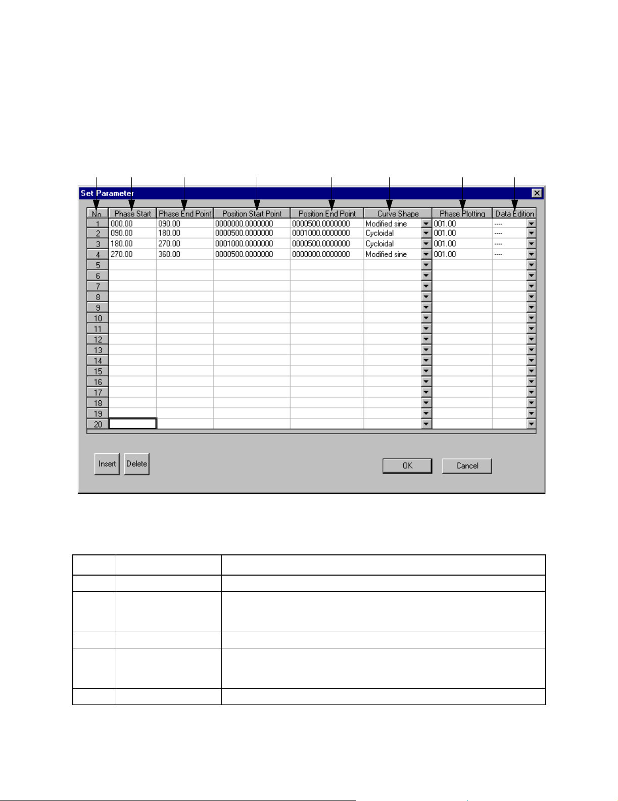
MotionWorks+™ Electronic Cam Tool
Parameter Setting
This window defines the cam profile data. The cam profile can be divided into a
maximum of 20 sections. Note: Closing this window without pressing the OK button
discards all changes.
1
2
34 5678
The table below details the items in the Set Parameter window.
Item Name Description
1 Number Cam data is displayed in sections. Up to 20 sections can be defined.
2 Phase Start The phase start value of each block is indicated.
This column is read only. The values are determined by data entered in
the Phase End Point column.
3 Phase End Set the phase end value of each section of the cam master.
4 Position Start Point The position start value of each section is indicated.
This column is read only. The values are determined by data entered in
the Position End Point column.
5 Position End Point Set the Position End Point value of each section of the slave.
79
Page 86

Electronic Cam Tool MotionWorks+™
Item Name Description
6 Curve Shape Select the cam curve shape from among the following 21 available
shapes. Data points are calculated along each section at the resolution
specified in the Phase Plotting column; the units used are those of the
master.
1. Straight line
2. Parabolic
3. Simple harmonic
4. Cycloidal
5. Modified trapezoid
6. Modified sine
7. Modified constant velocity
8. Asymmetrical cycloidal
9. Asymmetrical modified trapezoid
10. Trapecloid
11. One-dwell cycloidal m=1
12. One-dwell cycloidal m=2/3
13. One-dwell trapezoid m=1
14. One-dwell trapezoid
15. One-dwell trapezoid m=2/3
16. One-dwell modified sine
17. One-dwell trapecloid
18. No-dwell simple harmonic
19. No-dwell modified trapezoid
20. No-dwell modified constant velocity
21. NC2 curve
22. Tanget Matching
Display the combo box and click the desired shape.
7 Phase Plotting Set the resolution of the specified section. The Cam Tool generates
points along the specified curve shape at the interval of the master, in
user units. For example, if a certain section of the cam ranges between
0 ~ 90° and a phase plotting value is entered as 0.1, then points will be
generated every 0.1° and a total of 900 points will be generated for this
section of the cam.
8 Data (Provided/Not
Provided)
For a new parameter, “----” is displayed.
“Provided” or “Not Provided” is displayed depending on the necessity of
the graph data editing. This is useful when switching from the originally
entered data and modified cam profiles.
When the cam data has been entered, press OK to view the graphs.
80
Page 87

MotionWorks+™ Electronic Cam Tool
Viewing Cam Data
To change the data of existing files, open the Data Graph window and select Graph in
the menu bar.
1. Set Parameter
2. Set Style
3. Graph Data Editing
4. Shift Phase Direction
The Data Graph
Accessibility
To display the data graph, select:
• From the Main Menu > Display > Data Graph
This window shows the resulting cam profile from the information entered in the set
parameter window in graphical format. Use the arrow keys or the mouse to move
through the sections of the profile.
81
Page 88

Electronic Cam Tool MotionWorks+™
Data List
The numeric data of the cam curve is displayed by section.
1
2
3
1. List data
The numeric data of the cam curve of the specified section is displayed in each phase
division width.
2. Display Block No. Designation (Display Section)
Select the section to be displayed.
3. Display Block Information (Section Information)
The data quantity and ranges of the phase and position values of the designated section
are displayed.
When editing an insertion and/or deletion is performed, the data quantity changes.
4
82
Page 89

MotionWorks+™ Electronic Cam Tool
4. Setting Information
The effective torque, peak torque, and maximum rotation speed are automatically
calculated if the Machine/Motor Information data are set on the Set Style window.
These values are calculated based on the edited data and are then displayed.
The effective torque and peak torque are displayed with the rated torque as 100%.
Editing the Data List
1. Inserting row data
Move the cursor to a block before which a new line is to be inserted.
Click Edit in the menu bar and select Insert.
The following dialog box is displayed.
Input values for Phase Value and Position Value. Both values must be input. Click
the OK button, and the input data is inserted above the cell at which the cursor is
located.
The data becomes effective when inputting is confirmed and then is reflected in the
cam curve.
2. Deleting the data line
Move the cursor to the line to be deleted.
Click Edit in the menu bar and select Delete. The line at which the cursor is
located is then deleted.
3. Undo function
Selecting Edit > Undo from the menu bar of the Data List window cancels the
very last operation or input.
4. Resetting to the initial value
83
Page 90

Electronic Cam Tool MotionWorks+™
To reset all the edited data to the initial setting, click the data edit combo box
button, select Not Provided or ---- from Provided, Not Provided, and ----, and
click the OK button, which changes the data back to the initial value.
Control Graph
The speed, acceleration, and jerk are graphically displayed.
1
2
3
4
1. Cam Graph/Position
The cam curve is displayed.
5
6
7
8
9
10
2. Control Graph/Speed
The speed data calculated based on the cam curve data is displayed.
3. Control Graph/Acceleration
The acceleration data calculated based on the cam curve data is displayed.
4. Control Graph/Jerk
The jerk data calculated based on the cam curve data is displayed.
84
Page 91

MotionWorks+™ Electronic Cam Tool
5. Cursor Position/Phase
Enter the phase value or set with the arrow buttons.
By clicking a point on the cam graph, the phase and position values at which the
mouse is pointing are displayed.
The X axis of the cam graph (1) shows the phase (master) value and the Y axis shows
the position (slave) value.
6. Cursor Position/Position
The position value corresponding to the phase value set in step 5 (above) is displayed.
7. Speed Data/Scale (Y-axis) Selection
Select the graph display type of the speed data graph (2).
By selecting the radio button from Actual Data and Rated Rotation Speed Ratio (%),
the speed control graph changes.
8. Acceleration Data/Scale (Y-axis) Selection
Select the graph display type of the acceleration data graph (3).
By selecting the radio button from Actual Data and Rated Torque Ratio (%), the acceleration control graph changes.
9. Data/Maximum Value
The maximum values of speed, acceleration and jerk are displayed.
10. Data/Cursor Positions
The speed, acceleration and jerk of the phase and position values at which the mouse is
pointing on the cam graph are displayed.
85
Page 92
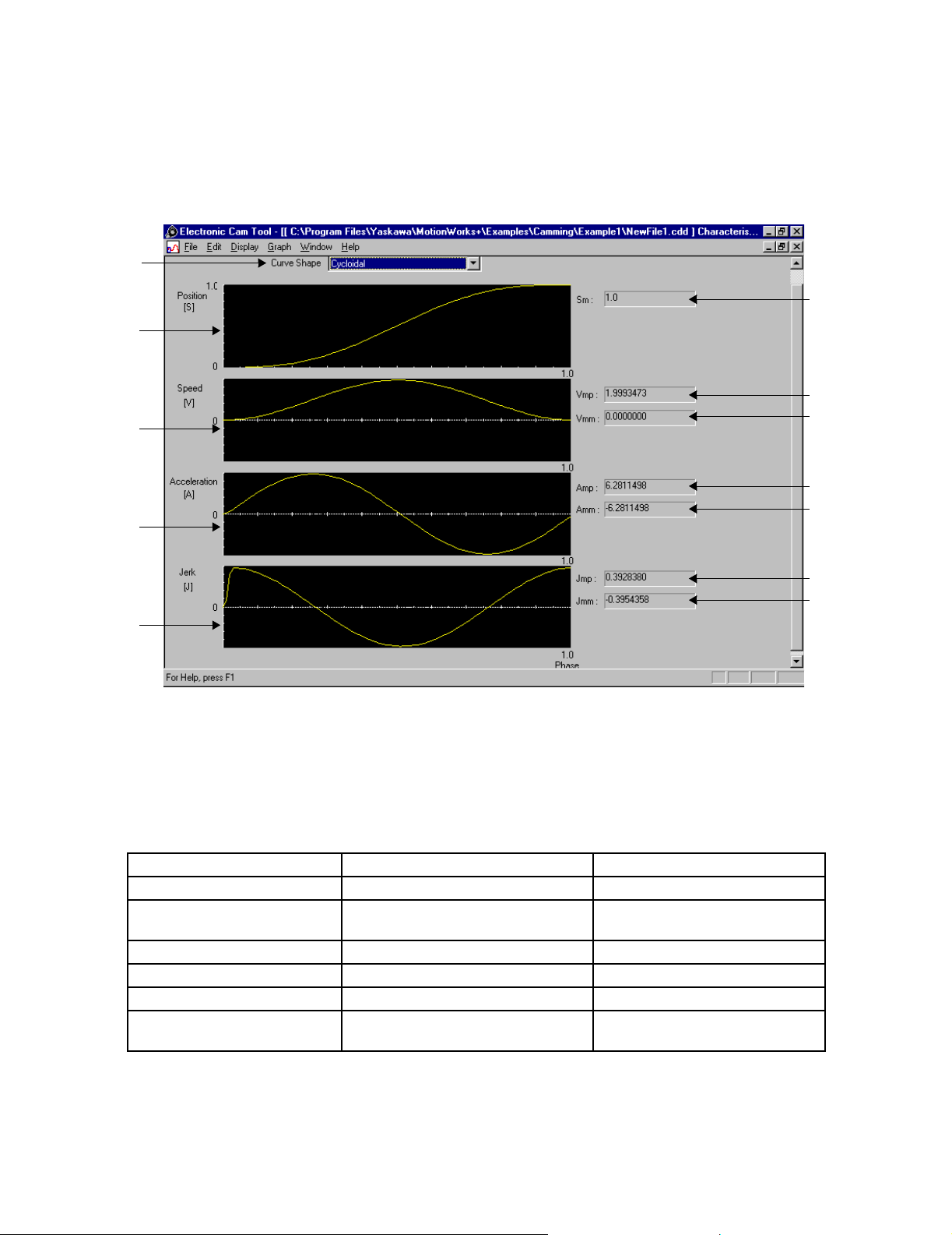
Electronic Cam Tool MotionWorks+™
Characteristic Curve Graph
The position, speed, acceleration, and jerk of the designated curve shape are displayed
as graphics.
1
6
2
7
3
8
9
10
4
5
1. Curve Shape
Display the curve shape combo box, scroll with the scroll bar, and click the curve
shape desired. The graph is then displayed in the curve shape desired.
Available curve shapes are presented below.
1. Straight line 2. Parabolic 3. Simple harmonic
4. Cycloidal 5. Modified trapezoid 6. Modified sine
7. Modified constant velocity 8. Asymmetrical cycloidal 9. Asymmetrical modified trapezoid
10. Trapecloid 11. One-dwell cycloidal m=1 12. One-dwell cycloidal m=2/3
13. One-dwell trapezoid m=1 14. One-dwell trapezoid 15. One-dwell trapezoid m=2/3
16. One-dwell modified sine 17. One-dwell trapecloid 18. No-dwell simple harmonic
19. No-dwell modified trapezoid 20. No-dwell modified constant veloc-
ity
21. NC2 curve
11
12
And New as of September 2002, “Tangent Matching” curve type.
86
Page 93

MotionWorks+™ Electronic Cam Tool
2. Position
The position data of the cam curve is displayed in the selected curve shape.
3. Speed
The speed data of the cam curve is displayed in the selected curve shape.
4. Acceleration
The acceleration data of the cam curve is displayed in the selected curve shape.
5. Jerk
The jerk data of the cam curve is displayed in the selected curve shape.
6. Sm
The maximum position value is displayed.
7. Vmp
The maximum positive speed is displayed.
8. Vmm
The maximum negative speed is displayed.
9. Amp
The maximum positive acceleration is displayed.
10. Amm
The maximum negative acceleration is displayed .
11. Jmp
The maximum positive jerk value is displayed .
12. Jmm
The maximum negative jerk value is displayed.
87
Page 94

Electronic Cam Tool MotionWorks+™
Compare Graphs
The currently edited cam data and either the cam data saved in the file or the external
data which was prepared by means other than the cam tool and saved in the .csv format
are displayed on the same graph for comparison.
4
1
5
1. Graph display
The currently edited cam data and data to be compared are displayed as graphics.
The currently edited cam data is displayed on a yellow line.
2. Cam Data
The file name of the currently edited cam data is displayed. Select the data to be
displayed.
Data Characteristics ... Position, Speed, Acceleration
3. Compared Data Selection
Select the data to be compared with the currently edited data. Up to three files can be
selected.
File Name: Displays the file name of the data to be compared.
2
3
Reference: Select the data file to be compared.
Data Characteristics: Position, Speed, Acceleration, External
88
Page 95

MotionWorks+™ Electronic Cam Tool
When the data to be compared is the cam data, select from Position, Speed, and
Acceleration. When the data to be compared is prepared by means other than the cam
tool, select External. Clicking the Reference button displays the following dialog
box. Select the file to be compared.
4. Display Cam Data
Select the display type of the currently edited cam data graph.
Scale: Set the scale of the graph (1) vertical axis to a value of 100 or less. The
default values are the absolute upper and lower limit values of the cam data.
5. Display Data
Select the display type of the comparison data graph. If the check is removed from the
check box, the compared graph disappears. If the check is put in the check box, the
graph is displayed again, because the data to be compared has been stored.
First Data Item No.: Set the first number of the data to be displayed as graphics.
Number of: Set the quantity of data from the first data number to the right of / (the
slash); the total data quantity is displayed.
Scale: Set the scale of the graph (1) vertical axis to a value of 100 or less. The
default values are the absolute upper and lower limit values of the data to be
compared.
Upper Limit: Displays the upper limit (maximum) value of the data to be
compared.
Lower Limit: Displays the lower limit (minimum) value of the data to be
compared.
89
Page 96

Electronic Cam Tool MotionWorks+™
Scale Conversion
The graph scale is set with the maximum absolute value of the displayed data as 100.
Change the scale setting when comparing data whose upper and lower limit values are
different, or when comparing data at a designated section.
(a) Comparison of data with different upper and lower limit values
(Ex.) Display Cam Data A Data Characteristics: PositionScale: 1000
Upper Limit: 1000 Lower Limit: 0
Display Data B Data Characteristics: PositionScale: 800.0000416
Upper Limit: 800.0000416 Lower Limit: 0
90
Page 97
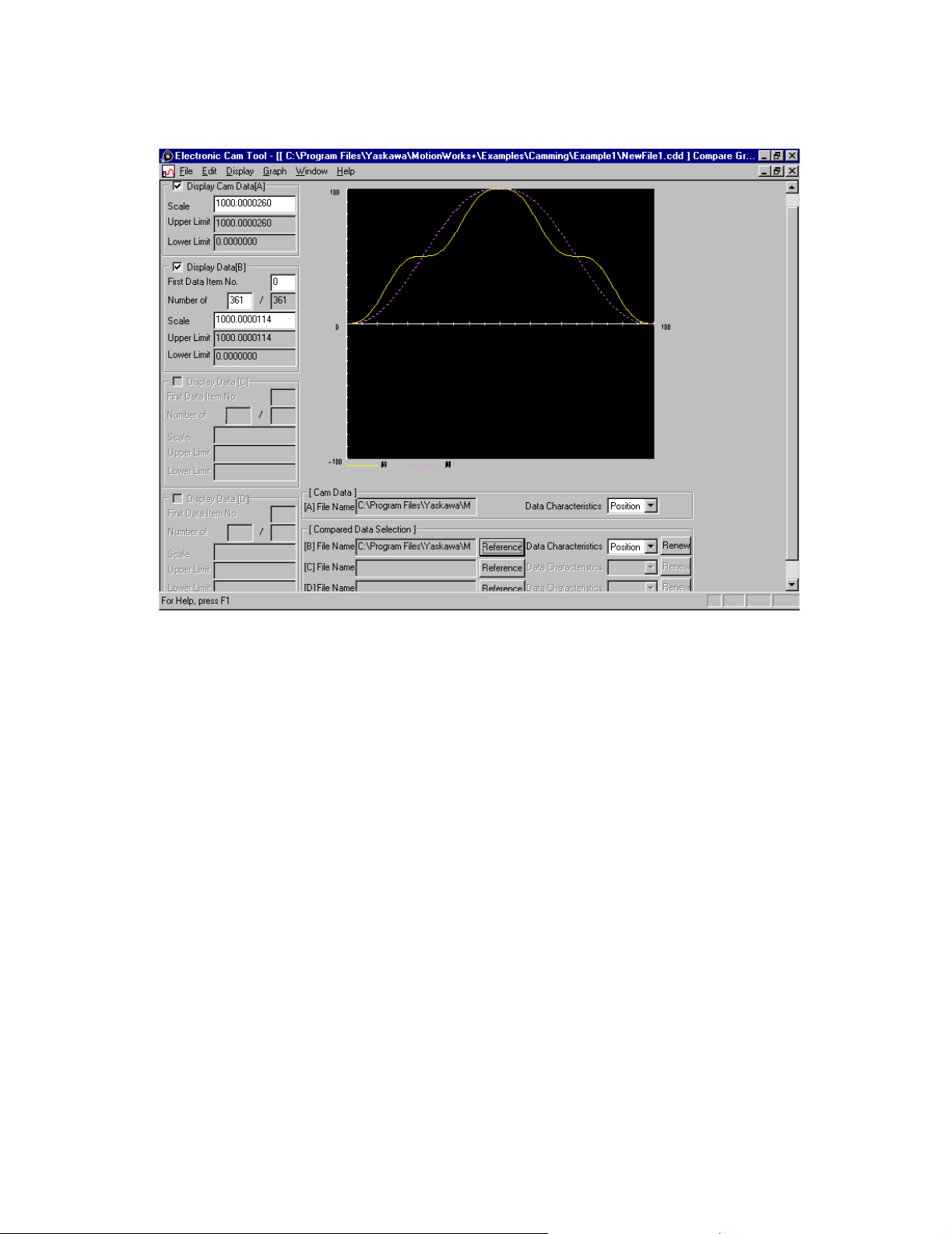
MotionWorks+™ Electronic Cam Tool
The scales for A and B are set to 1000.
(b) Comparison of data at a designated section
(Ex.) Comparison of A and B
Display Cam Data A Data Characteristics: Position Scale: 1000
Upper Limit: 1000 Lower Limit: 0
First Data Item No.: 0 Number of: 361
Display Data [B] Data Characteristics: Position
Scale: 1000
Upper Limit: 1000 Lower Limit: 0
91
Page 98

Electronic Cam Tool MotionWorks+™
First Data Item No.: 5 Number of: 200
92
Page 99

MotionWorks+™ Electronic Cam Tool
Setting Grid Line
Set whether to display the graph grid line at the data graph window. When the data
graph is displayed, select Display in the menu bar and then Option. The following
dialog box appears.
1
2
1. Phase Axis
Set whether to display or to hide the phase axis grid line by clicking the radio button.
2. Position Axis
Set whether to display or to hide the position axis grid line by clicking the radio
button.
The initial setting is Display.
93
Page 100

Electronic Cam Tool MotionWorks+™
Editing Cam Data
From the main menu of the electronic cam tool, select Graph > Edit Graph Data.
Position the mouse over a point in the graph. The slave position of that point appears in
the editing data box (#6 below).
10
11
2
3
4
1
1. Edit graph
The graph can be edited with the mouse. Refer to “Using the Mouse” on page 96.
2. Phase
Select a phase (master) value. This allows editing the corresponding position (slave)
value.
5
6
7
8
9
3. Phase/Change Value Adjustment
Sets the adjustment value when the phase value is set with the slide bar.
4. Phase/Scale
Select the phase display scale. When the graph is expanded, editing is easy.
5. Position/Reference Data
Position value corresponding to the phase value set in item 2 above is displayed.
94
 Loading...