

Page 1
MotionSuite™ Series Machine Controller
Software Manual
Page 2

MotionSuite™ Series Machine Controller Software Manual Table of Contents
1 Outline of Programing Unit ...................................................................................... 1-1
1.1 Basic Specifications ............................................................................................ 1-2
1.1.1 Recommended PC Specifications .............................................................. 1-2
1.2 System Configuration ......................................................................................... 1-3
1.2.1 MotionWorks™ System ............................................................................ 1-3
1.3 Basic Functions ................................................................................................... 1-4
1.3.1 Basic Functions List ................................................................................... 1-4
1.3.2 Detailed Function List ............................................................................... 1-5
1.3.3 Function Tree ............................................................................................. 1-8
2 Installation ................................................................................................................. 2-1
2.1 Installation Procedures ........................................................................................ 2-2
2.1.1 Preparing the Installation Disk .................................................................. 2-2
2.1.2 Set-up Preparation ...................................................................................... 2-2
2.1.3 Starting Set-up ........................................................................................... 2-3
2.1.4 User Registration ....................................................................................... 2-4
2.1.5 Selecting Destination Directory ................................................................. 2-5
2.1.6 Selecting Program Folder .......................................................................... 2-6
2.1.7 Modifying Input Information ..................................................................... 2-7
2.1.8 Starting File Copy ...................................................................................... 2-8
2.1.9 Completing File Copy ................................................................................ 2-9
2.1.10 Completing Set-up ................................................................................... 2-10
2.1.11 Created Folders Upon Installing .............................................................. 2-10
2.2 Communication Settings ................................................................................... 2-12
2.2.1 Calling up Communication Manager ....................................................... 2-12
2.2.2 Setting Communication Port .................................................................... 2-13
2.2.3 Saving Communication Port Setting Values ........................................... 2-14
2.2.4 Communication Process Completion ....................................................... 2-14
3 Basic Operation.......................................................................................................... 3-1
3.1 MotionWorks™ Basic Operation ....................................................................... 3-2
3.1.1 Basic Structural Elements of the MotionWorks™ Window ...................... 3-2
3.1.2 Keyboard and Mouse ................................................................................. 3-4
3.1.3 Cursor ......................................................................................................... 3-4
3.1.4 Title Bar ..................................................................................................... 3-5
3.1.5 Connection Information Bar ...................................................................... 3-6
3.1.6 Menu Bar ................................................................................................... 3-6
3.1.7 Window ...................................................................................................... 3-7
3.1.8 Boxes ......................................................................................................... 3-9
3.1.9 Scroll ........................................................................................................ 3-10
i
Page 3

MotionSuite™ Series Machine Controller Software Manual Table of Contents
3.1.10 Go to Page ................................................................................................ 3-10
3.2 Shortcut Keys .................................................................................................... 3-11
3.2.1 Major Keys Generally Used in Windows ................................................ 3-11
3.2.2 Major Keys Used in Dialog Boxes .......................................................... 3-11
3.3 Starting and Closing MotionWorks™ .............................................................. 3-12
3.3.1 Starting MotionWorks™ ......................................................................... 3-12
3.3.2 Selecting Controller ................................................................................. 3-13
3.3.3 Closing MotionWorks™ .......................................................................... 3-15
3.3.4 System Shut-off ....................................................................................... 3-17
3.4 Global Menus .................................................................................................... 3-18
3.4.1 Global Menu Items .................................................................................. 3-18
3.4.2 File (F) Menu ........................................................................................... 3-19
3.4.3 View (V) Menu ........................................................................................ 3-20
3.4.4 Window (W) Menu .................................................................................. 3-21
3.4.5 Help (H) Menu ......................................................................................... 3-23
4 File Manager .............................................................................................................. 4-1
4.1 Window Configuration ....................................................................................... 4-3
4.1.1 Folder and File Names ............................................................................... 4-4
4.1.2 File Manager Menu .................................................................................... 4-5
4.1.3 Global Menus ............................................................................................. 4-7
4.1.4 Menus for the Root and Group Folders ..................................................... 4-8
4.1.5 Menus for the Order Folder ....................................................................... 4-9
4.1.6 Menus for the Controller .......................................................................... 4-10
4.1.7 Menus for Program, Definition, and Table Data Folder .......................... 4-11
4.1.8 Menus for Interrupt DWG, Function, High Scan, Starting DWG,
and Low Scan Folder ............................................................................... 4-12
4.1.9 Menus for Program File ........................................................................... 4-14
4.1.10 Menus for Motion Folder ......................................................................... 4-16
4.1.11 Menus for Motion Group Folder ............................................................. 4-17
4.1.12 Menus for Motion Program File .............................................................. 4-18
4.1.13 Menus for Group Definition and Motion Parameter File ........................ 4-19
4.1.14 Tree-like Display Window ....................................................................... 4-20
4.1.15 List Display Window ............................................................................... 4-22
4.1.16 Detail Display Window ........................................................................... 4-26
4.2 Rename ............................................................................................................. 4-29
4.3 New Controller Registration ............................................................................. 4-31
4.3.1 Creating New Group Folder .................................................................... 4-31
4.3.2 Creating New Order Folder ..................................................................... 4-32
4.3.3 Creating New Controller Folder .............................................................. 4-34
ii
Page 4

MotionSuite™ Series Machine Controller Software Manual Table of Contents
4.4 Changing Controller Configuration .................................................................. 4-39
4.5 Deleting Folder or File ...................................................................................... 4-43
4.6 CPU Log-on/Log-off ........................................................................................ 4-45
4.6.1 Logging on to the CPU ............................................................................ 4-45
4.6.2 Logging off from the CPU ....................................................................... 4-46
4.7 Switching On-line/Off-line Mode ..................................................................... 4-48
4.8 Switching CPU Status ....................................................................................... 4-50
4.9 Editing DWG/Function Program ...................................................................... 4-52
4.9.1 Copying Program ..................................................................................... 4-52
4.9.2 Setting Disable ......................................................................................... 4-53
4.9.3 Switching Sub-program Unit Display ...................................................... 4-54
4.10 Updating Information ...................................................................................... 4-55
4.11 File Operation of the Motion Program ............................................................. 4-56
4.11.1 Copying Program ..................................................................................... 4-56
4.12 User Management ............................................................................................. 4-57
4.12.1 Registering A New User .......................................................................... 4-58
4.12.2 Changing User Information ..................................................................... 4-60
4.12.3 Deleting User ........................................................................................... 4-61
4.12.4 Saving User Manager Data ...................................................................... 4-62
4.12.5 Setting Default User ................................................................................. 4-62
4.13 File Transfer ...................................................................................................... 4-64
4.13.1 Opening File Transfer Window ............................................................... 4-64
4.13.2 All Transfer .............................................................................................. 4-65
4.13.3 Individual Transfer .................................................................................. 4-75
4.13.4 Changing Transfer Source and Transfer Destination .............................. 4-78
4.13.5 Setting Detailed Data ............................................................................... 4-78
4.13.6 Starting Transfer ...................................................................................... 4-79
4.13.7 Continuous Transfer ................................................................................ 4-80
4.13.8 Closing File Transfer Window ................................................................ 4-81
5 Engineering Manager................................................................................................. 5-1
5.1 Automatic Starting of the Engineering Manager ................................................ 5-2
5.1.1 Automatic Starting ..................................................................................... 5-2
5.1.2 Basic Function ........................................................................................... 5-3
5.1.3 Menus Displayed When the Function Windows are not Open .................. 5-3
5.1.4 Menus Displayed When the Function Windows are Open ........................ 5-5
iii
Page 5

MotionSuite™ Series Machine Controller Software Manual Table of Contents
5.2 Closing the Engineering Manager ...................................................................... 5-6
6 Module Configuration................................................................................................ 6-1
6.1 Opening the Module Configuration Window ..................................................... 6-2
6.1.1 Calling up from the File Manager Window ............................................... 6-2
6.1.2 Calling up from the Engineering Manager Window ................................. 6-2
6.1.3 Main Module Configuration Window ....................................................... 6-3
6.2 Module Configuration ......................................................................................... 6-4
6.2.1 Module Configuration Menus .................................................................... 6-4
6.2.2 Setting the Module Configuration ............................................................. 6-5
6.2.3 Saving the Module Configuration .............................................................. 6-7
6.2.4 Deleting the Module Configuration ........................................................... 6-8
6.2.5 Closing the Module Configuration ............................................................ 6-8
6.3 Opening the Definition Window of the Module in the Slot ............................... 6-9
6.4 Serial Definition ................................................................................................ 6-10
6.4.1 Serial Definition Menus ........................................................................... 6-10
6.4.2 Setting the Serial Definition .................................................................... 6-10
6.4.3 Saving the Serial Definition ..................................................................... 6-13
6.4.4 Deleting the Serial Definition .................................................................. 6-13
6.4.5 Closing the Serial Definition ................................................................... 6-14
6.5 Local I/O Configuration .................................................................................... 6-15
6.5.1 Local I/O Definition Menus ..................................................................... 6-15
6.5.2 Setting the Local I/O Configuration ........................................................ 6-16
6.5.3 Saving the Local I/O Configuration ......................................................... 6-17
6.5.4 Deleting the Local I/O Configuration ...................................................... 6-18
6.5.5 Closing the Local I/O Configuration ....................................................... 6-19
6.6 Network Configuration ..................................................................................... 6-20
6.6.1 Network Configuration Menus ................................................................ 6-21
6.6.2 Setting the Network Configuration .......................................................... 6-21
6.6.3 Saving the Network Configuration .......................................................... 6-28
6.6.4 Deleting the Network Configuration ....................................................... 6-28
6.6.5 Closing the Network Configuration ......................................................... 6-29
7 System Data Definition.............................................................................................. 7-1
7.1 Global System Data Setting Operations ............................................................. 7-3
7.1.1 On-line Mode and Off-line Mode .............................................................. 7-3
7.1.2 Types of Definition Screens ...................................................................... 7-4
7.1.3 Definition Screen Call-out ......................................................................... 7-4
7.1.4 New Definitions Files ................................................................................ 7-6
iv
Page 6

MotionSuite™ Series Machine Controller Software Manual Table of Contents
7.2 Group Definition ................................................................................................. 7-7
7.2.1 Structure of Group Definition Window ..................................................... 7-7
7.2.2 Group Definition Setting ........................................................................... 7-7
7.2.3 Saving Group Definitions ........................................................................ 7-11
7.2.4 Group Definition Deletion ....................................................................... 7-11
7.2.5 Closing Group Definition ........................................................................ 7-12
7.3 Motion Parameter Definition ............................................................................ 7-13
7.3.1 Structure of Motion Parameter Window .................................................. 7-13
7.3.2 Fixed Parameter Setting ........................................................................... 7-14
7.3.3 Set-up Parameter ...................................................................................... 7-18
7.3.4 Servo Amplifier (Servopack) Parameter Setting ..................................... 7-23
7.3.5 Parameter Monitor Display ...................................................................... 7-26
7.3.6 Saving Motion Parameter Definitions ..................................................... 7-28
7.3.7 Deleting Motion Parameter Definitions ................................................... 7-29
7.3.8 Closing Motion Parameter Definition ...................................................... 7-29
7.4 System Configuration ....................................................................................... 7-30
7.4.1 Structure of the System Configuration Window ...................................... 7-30
7.4.2 System Configuration Data Setting ......................................................... 7-31
7.4.3 Setting of Common Memory Assignment Data ...................................... 7-34
7.4.4 PLC Status Change .................................................................................. 7-36
7.4.5 Saving System Configuration .................................................................. 7-38
7.4.6 Closing System Configuration ................................................................. 7-38
7.5 Scan Time Setting ............................................................................................. 7-39
7.5.1 Structure of the Scan Time Window ........................................................ 7-39
7.5.2 Scan Time Setting .................................................................................... 7-40
7.5.3 Saving Scan Time Settings ...................................................................... 7-41
7.5.4 Closing Scan Time Settings ..................................................................... 7-41
7.6 Application Information ................................................................................... 7-42
7.6.1 Structure of Application Information Window......................................... 7-42
7.6.2 Application Information Setting .............................................................. 7-43
7.6.3 Saving Application Information .............................................................. 7-44
7.6.4 Closing Application Information ............................................................. 7-44
7.7 Data Trace ......................................................................................................... 7-45
7.7.1 Structure of Data Trace Window ............................................................. 7-45
7.7.2 Data Trace Definition .............................................................................. 7-47
7.7.3 Saving Data Trace Definitions ................................................................. 7-51
7.7.4 Deleting Data Trace Definitions .............................................................. 7-51
7.7.5 Data Trace Data Writing and Deletion .................................................... 7-51
7.7.6 Trace Data Reading ................................................................................. 7-55
7.7.7 Data Trace Start ....................................................................................... 7-55
7.7.8 Trace Data List Display ........................................................................... 7-56
v
Page 7

MotionSuite™ Series Machine Controller Software Manual Table of Contents
7.7.9 Trace Data Trend Graph Display ............................................................. 7-61
7.7.10 Closing Data Trace Definition ................................................................. 7-64
7.8 Fault Monitor Data ............................................................................................ 7-65
7.8.1 Structure of the Fault Monitor Window .................................................. 7-65
7.8.2 Failures ..................................................................................................... 7-66
7.8.3 Annunciator Signal Configuration ........................................................... 7-70
7.8.4 Fault Status .............................................................................................. 7-71
7.8.5 Display of Current Faults ......................................................................... 7-73
7.8.6 Fault Trace ............................................................................................... 7-74
7.8.7 Saving Fault Monitor Data ...................................................................... 7-75
7.8.8 Deletion Fault Monitor Data .................................................................... 7-75
7.8.9 Closing Fault Monitor Data ..................................................................... 7-75
8 Ladder Programming ................................................................................................. 8-1
8.1 Property Settings ................................................................................................. 8-3
8.1.1 Configuration of the Property Window ..................................................... 8-3
8.1.2 Definition of Structural Data ..................................................................... 8-4
8.1.3 I/O Definition ............................................................................................. 8-6
8.1.4 Symbol Definition ...................................................................................... 8-7
8.1.5 # Register Lists ........................................................................................ 8-12
8.1.6 Update History ......................................................................................... 8-16
8.1.7 Property Data Storage .............................................................................. 8-17
8.2 Ladder Program Editing .................................................................................... 8-19
8.2.1 Ladder Program Window Structure ......................................................... 8-19
8.2.2 Display Mode Switching ......................................................................... 8-25
8.2.3 Command Input ....................................................................................... 8-26
8.2.4 Program Editing ....................................................................................... 8-38
8.2.5 Creation of Branch Circuits ..................................................................... 8-43
8.2.6 Disable Coil Setting ................................................................................. 8-52
8.2.7 Jump ......................................................................................................... 8-54
8.2.8 Current Value Display ............................................................................. 8-55
8.2.9 Comment Creation ................................................................................... 8-56
8.2.10 Ladder Program Storage .......................................................................... 8-57
8.2.11 Ladder Program Printing ......................................................................... 8-59
8.2.12 Ladder Program Edit Completion ............................................................ 8-60
8.3 Tabular Format Program Creation .................................................................... 8-61
8.3.1 Tabular Format Program Window Configuration ................................... 8-61
8.3.2 Input Mode Switching ............................................................................. 8-64
8.3.3 Parameter Table ( # register) Data Input ................................................. 8-65
8.3.4 Parameter Table (M register) Data Input ................................................. 8-66
8.3.5 I/O Conversion Table Data Input ............................................................. 8-67
8.3.6 Interlock Table Data Input ....................................................................... 8-68
vi
Page 8

MotionSuite™ Series Machine Controller Software Manual Table of Contents
8.3.7 Parts Assembling Table Data Input ......................................................... 8-71
8.3.8 Table Editing ............................................................................................ 8-73
8.3.9 Saving Tabular Format Programs ............................................................ 8-77
8.3.10 Printing of Tabular Format Programs ...................................................... 8-77
8.3.11 Ending Tabular Format Program Creation .............................................. 8-77
8.4 Tuning Panel Creation ...................................................................................... 8-78
8.4.1 Tuning Panel Window Structure .............................................................. 8-78
8.4.2 Input Mode Switching ............................................................................. 8-79
8.4.3 Tuning Panel Setting ................................................................................ 8-80
8.4.4 Editing the Tuning Panel ......................................................................... 8-81
8.4.5 Saving the Tuning Panel .......................................................................... 8-81
8.4.6 Printing from the Tuning Panel ............................................................... 8-82
8.4.7 Ending Tuning Panel Creation ................................................................. 8-82
8.5 C Register Creation ........................................................................................... 8-83
8.5.1 C Register List Window Configuration ................................................... 8-83
8.5.2 Table Operation with the List Window ................................................... 8-84
8.5.3 Structure of C Register Table Window .................................................... 8-85
8.5.4 Input Mode Switching ............................................................................. 8-87
8.5.5 C Register Table Setting .......................................................................... 8-87
8.5.6 Editing of C Register Tables .................................................................... 8-88
8.5.7 Saving C Register Tables ......................................................................... 8-89
8.5.8 Printing of C Register Table .................................................................... 8-89
8.5.9 Ending C Register Table Creation ........................................................... 8-89
8.6 Table Data Creation .......................................................................................... 8-90
8.6.1 Summary of Table Data Creation Procedure ........................................... 8-90
8.6.2 Structure of Table Data List Window ...................................................... 8-91
8.6.3 Table Operation in the List Window ....................................................... 8-94
8.6.4 Structure of the Column Attribute Window ............................................ 8-96
8.6.5 Setting Column Attributes ....................................................................... 8-97
8.6.6 Column Attribute Editing ........................................................................ 8-99
8.6.7 Saving Row Attributes ........................................................................... 8-102
8.6.8 Data Window Structure ......................................................................... 8-103
8.6.9 Table Data Setting ................................................................................. 8-104
8.6.10 Table Data Editing ................................................................................. 8-104
8.6.11 Saving Table Data .................................................................................. 8-105
8.6.12 Ending Table Data Creation .................................................................. 8-105
9 Motion Programming................................................................................................. 9-1
9.1 Outline of Motion Program Creation .................................................................. 9-2
9.2 Motion Properties ............................................................................................... 9-3
vii
Page 9

MotionSuite™ Series Machine Controller Software Manual Table of Contents
9.3 Motion Editor ...................................................................................................... 9-5
9.3.1 Starting the Motion Editor ......................................................................... 9-5
9.3.2 Motion Editor Window .............................................................................. 9-6
9.3.3 Motion Editor Menu .................................................................................. 9-7
9.3.4 Motion Editor Commands ......................................................................... 9-9
9.3.5 Special Motion Editor Commands ........................................................... 9-16
9.3.6 Closing the Motion Editor ....................................................................... 9-19
9.4 Compiler ........................................................................................................... 9-20
9.4.1 Compiler Operation ................................................................................. 9-20
9.4.2 Compiler Operation Steps ........................................................................ 9-21
9.4.3 Normal Completion of Compilation ........................................................ 9-21
9.4.4 Abnormal Completion of Compilation .................................................... 9-21
10 Monitor .................................................................................................................... 10-1
10.1 Register List ...................................................................................................... 10-2
10.1.1 Structure of the Register/Register List Window ...................................... 10-2
10.1.2 Register Value Display ............................................................................ 10-3
10.1.3 Display Format Change ........................................................................... 10-5
10.1.4 Register Value Change ............................................................................ 10-8
10.1.5 Closing the Register/Register List Windows ........................................... 10-8
10.2 Motion Program Monitor .................................................................................. 10-9
10.2.1 Structure of the Motion Program Monitor Window ................................ 10-9
10.2.2 Monitor Display of the Motion Program ................................................. 10-9
10.2.3 Releasing and Reviewing the Monitor Display ..................................... 10-11
10.3 Position Monitor ............................................................................................. 10-13
10.3.1 Structure of the Position Monitor Window ............................................ 10-13
10.3.2 Position Monitor Display ....................................................................... 10-14
10.3.3 Closing the Position Monitor ................................................................. 10-16
10.4 Task Monitor ................................................................................................... 10-17
10.4.1 Structure of the Task Monitor Window ................................................. 10-17
10.4.2 Status View of the Motion Program ...................................................... 10-18
10.4.3 Closing the Task Monitor ...................................................................... 10-20
10.5 Motion Alarm ................................................................................................. 10-21
10.5.1 Structure of the Motion Alarm Window ................................................ 10-21
10.5.2 Motion Alarm View ............................................................................... 10-23
10.5.3 Closing the Motion Alarm ..................................................................... 10-24
viii
Page 10

MotionSuite™ Series Machine Controller Software Manual Table of Contents
11 Debug Operation...................................................................................................... 11-1
11.1 Structure of the Debug Window ....................................................................... 11-2
11.1.1 Opening the Debug Window ................................................................... 11-2
11.1.2 Debug Menus ........................................................................................... 11-3
11.1.3 Debug Tool Icons ..................................................................................... 11-4
11.1.4 Debug Function Keys .............................................................................. 11-5
11.1.5 Debug Status Bar ..................................................................................... 11-5
11.2 Debug Operation ............................................................................................... 11-6
11.2.1 Debug Mode ON/OFF ............................................................................. 11-6
11.2.2 Debug Operation Window ....................................................................... 11-7
11.2.3 Step Execution ......................................................................................... 11-9
11.2.4 Multi-step Execution .............................................................................. 11-11
11.2.5 Hold Enable/Disable .............................................................................. 11-12
11.2.6 Abort ...................................................................................................... 11-13
11.2.7 Current Value Update ............................................................................ 11-15
11.2.8 Editing During the Debug Operation ..................................................... 11-16
11.2.9 Restrictions During the Debug Operation ............................................. 11-20
12 Printing..................................................................................................................... 12-1
12.1 Structure of Print Manager Window ................................................................. 12-2
12.2 Program Print Data Selection ........................................................................... 12-5
12.2.1 Program Print Set-up ............................................................................... 12-5
12.2.2 Detailed Program Setting ......................................................................... 12-7
12.3 Selecting Register Print Data .......................................................................... 12-10
12.3.1 Register Print Settings ........................................................................... 12-10
12.3.2 Detailed Register Settings ...................................................................... 12-10
12.4 Selecting Definition Print Data ....................................................................... 12-13
12.4.1 Definition Print Settings ........................................................................ 12-13
12.4.2 Detailed Definition Settings ................................................................... 12-13
12.5 Motion Print Data Selection ........................................................................... 12-15
12.5.1 Motion Print Set-up ............................................................................... 12-15
12.5.2 Detailed Motion Setting ......................................................................... 12-16
12.6 Print Execution ............................................................................................... 12-17
12.7 Print Status Display from the List Manager ................................................... 12-18
12.7.1 Structure of List Manager Window ....................................................... 12-18
12.7.2 Print Status Display ............................................................................... 12-19
12.7.3 Print Cancellation .................................................................................. 12-20
ix
Page 11

MotionSuite™ Series Machine Controller Software Manual Table of Contents
12.8 Editing of Print Setting File ............................................................................ 12-21
12.8.1 Reading Print Setting Files .................................................................... 12-21
12.8.2 Deletion of Print Setting Files ............................................................... 12-21
12.8.3 Saving Print Setting Files ...................................................................... 12-21
12.9 Sample of Print Results ................................................................................... 12-23
12.9.1 Cover Sheet Sample ............................................................................... 12-23
12.9.2 Contents Sample .................................................................................... 12-24
12.9.3 Drawing Tree Sample ............................................................................ 12-25
12.9.4 Drawing List Sample ............................................................................. 12-25
12.9.5 Drawing Program Print Sample ............................................................. 12-26
12.9.6 M Register Map Print Sample ............................................................... 12-28
12.9.7 M Register List Sample ......................................................................... 12-29
13 Compilation Error Message List.............................................................................. 13-1
13.1 Compilation Error Message List ....................................................................... 13-2
14 Command List.......................................................................................................... 14-1
14.1 Command List for Drawing/Function Creation ................................................ 14-2
14.1.1 Program Control Commands ................................................................... 14-2
14.1.2 Direct Input Commands ........................................................................... 14-3
14.1.3 Ladder Circuit Commands ....................................................................... 14-3
14.1.4 Logical Operation Commands ................................................................. 14-4
14.1.5 Numerical Operation Commands ............................................................ 14-4
14.1.6 Numerical Conversion Commands .......................................................... 14-5
14.1.7 Numerical Comparison Commands ......................................................... 14-5
14.1.8 Data Operation Commands ...................................................................... 14-6
14.1.9 Basic Function Commands ...................................................................... 14-7
14.1.10 DDC Commands ...................................................................................... 14-7
14.1.11 Table Data Operation Commands ............................................................ 14-8
x
Page 12

MotionSuite™ Series Machine Controller Software Manual Chapter 1: Outline of Programming Unit
1 Outline of Programing Unit
This chapter explains the MotionWorks™ programing unit and outlines its
function using the MP9xx.
1.1 Basic Specifications ............................................................................................ 1-2
1.1.1 Recommended PC Specifications .............................................................. 1-2
1.2 System Configuration ......................................................................................... 1-3
1.2.1 MotionWorks™ System ............................................................................ 1-3
1.3 Basic Functions ................................................................................................... 1-4
1.3.1 Basic Functions List ................................................................................... 1-4
1.3.2 Detailed Function List ............................................................................... 1-5
1.3.3 Function Tree ............................................................................................. 1-8
1-1
Page 13

MotionSuite™ Series Machine Controller Software Manual Chapter 1: Outline of Programming Unit
1.1 Basic Specifications
MotionWorks™ is a programing software used to program the MotionSuite™ series
machine controller on a PC.
MotionWorks™ and the controller are connected by an RS-232C communication interface.
Installation CD-ROM
.
RS-232C
Programing Unit
1.1.1 Recommended PC Specifications
The recommended PC specifications for operating MotionWorks™ are shown as follows:
Hardware/Software Specifications
PC Architecture IBM PC compatible
CPU Pentium 133MHZ or greater (or equivalents)
Display Resolution 800 × 600 dot or greater
Memory 32MB or greater
Hard Disk 100MB Free space
Operating System Windows95/98/NT
Controller
1-2
Page 14

MotionSuite™ Series Machine Controller Software Manual Chapter 1: Outline of Programming Unit
1.2 System Configuration
This section explains the MotionWorks™ system configuration in a Windows95 environment. MotionWorks™ is composed of File Manager, Engineering Manager, and List
Manager which are in charge of user interface, as well as the Communication Process
which handles communication with the controller. Various programing tools are included
in these management programs.
1.2.1 MotionWorks™ System
The MotionWorks™ software runs multiple programs simultaneously in a Windows
environment.
Windows95
MotionWorks™
File Manager
PC
MotionWorks™
Engineering Manager
MotionWorks™
List Manager
MotionWorks™
Communication Process
Controller
Programing Tool
Servo Amp. Servo Amp.
...
1-3
Axis 1
Axis 2
Page 15

MotionSuite™ Series Machine Controller Software Manual Chapter 1: Outline of Programming Unit
1.3 Basic Functions
In this section, all functions provided by MotionWorks™ are shown in the following list.
1.3.1 Basic Functions List
MotionWorks™ basic functions can be classified in nine (9) primary functions. The
nine primary functions are further categorized into secondary and tertiary functions.
Number Primary Function Secondary Function
File Management
1 File Manager
2 System Configuration
3 Module Configuration
4Tools
5 Document Print
6 Ladder Programing
7 C Register C Register Creation
8 Table Data Definition Table Data Creation
9 Motion Programing
User Management
File Transfer
System Configuration
Scan Time Set-up
Application Information
Fault Monitor
Data Trace
Group Definition
Motion Parameter
Configuration Definition
General Serial Definition
Local I/O Definition
Network Definition
Register List
Cross Reference
Disable Coil List
Register Number Search/replace
Comment Bar
Property Set-up
Main Program Creation
Table Format Program Creation
Tuning Panel Creation
Motion Edit
Position Monitor
Task Monitor
Motion Alarm
1-4
Page 16

MotionSuite™ Series Machine Controller Software Manual Chapter 1: Outline of Programming Unit
1.3.2 Detailed Function List
In addition to the primary and the secondary functions, the tertiary functions are listed
as follows:
Primary Functions Secondary Functions Tertiary Functions
Rename
New PLC Registration
PLC Information Change
Folder/file Deletion
File Management
File Manager
User Management
File Transfer
System Configuration
Scan Time
Application Information
System Configuration
Fault Monitor
Log On/log Off To CPU
On-line/off-line Mode Switching
CPU Status Switching
Dwg/function Program Edit
Information Update
User Management
Default User Set-up
Batch Transfer
Individual Transfer
Continuous Transfer
Flash Memory Transfer
Multi-CPU Transfer
System Configuration
Configuration Data Save
PLC Selection
Scan Time Set-up
Set-up Data Save
Information Set-up
Information Save
Fault Definition
Annunciator Signal Definition
Fault Status Display
Fault Display During Operation
Fault Trace Display
Definition Data Save
Definition Data Deletion
1-5
Page 17

MotionSuite™ Series Machine Controller Software Manual Chapter 1: Outline of Programming Unit
Trace Data Definition
Definition Data Save
Definition Data Deletion
Data Trace
System Configuration
Group Definition
Motion Parameter
Configuration Definition
General Serial Definition
Module Configuration
Local I/O Definition
Network Definition
Register List
Cross Reference Cross Reference Execution
Tools
Document Print
Disable Coil List Disable Coil Search
Register Number Search/Replace
Comment Bar
Trace Data Write
Trace Data Read
Data Trace Start
Trace Data List Display
Trend Graph Display
Group Set-up
Save
Delete
Parameter Set-up
Save
Delete
Monitor
Configuration Set-up
Save
Delete
Serial Port Set-up
Save
Delete
Local I/O Set-up
Save
Delete
Network Set-up
Save
Delete
Monitor Register Value
Change Display Format
Change Register Value
Data Input
Search/Replace Execution
Comment Creation
Update Comment Information
Print Data Set-up
Print Execution
Print Status Display
Print Set-up File Edit
Print Result Sample
1-6
Page 18

MotionSuite™ Series Machine Controller Software Manual Chapter 1: Outline of Programming Unit
Information Definition
Input/Output Definition
Property Set-up
Main Program Creation
Ladder Programing
Table Format Program Creation
Tuning Panel Creation
C Register C Register Creation
Table Data Definition Table Data Creation
Motion Edit
Motion Programing
Position Monitor Display Current Position
Task Monitor Display Task Status
Motion Alarm Display Error
Symbol Definition
#Register List
Revision History
Property Set-up Data Save
Display Mode Switch
Command Input
Program Save
Program Print
Input Mode Switch
Table Data Input
Table Edit
Table Format Program Save
Input Mode Switching
Definition Data Input
Tuning Panel Edit
Tuning Panel Save
C Register Table List
C Register Table Creation
Table Dat a L ist
String Data Attribute Set-up
Table Data Set-up
Motion Property
Import/export
Text Edit
Debug
Position Instruction
1-7
Page 19
MotionSuite™ Series Machine Controller Software Manual Chapter 1: Outline of Programming Unit
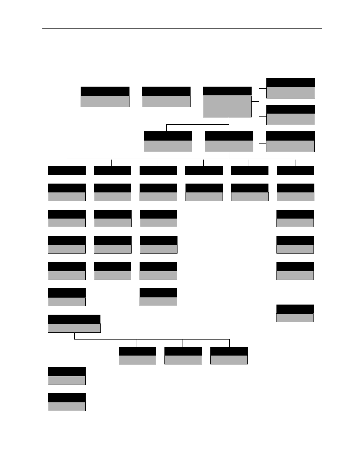
1.3.3 Function Tree
Each function unfolded from the File Manager Window is shown as follows:
Ladder Converter
C
Communication Process
List Manager
File Manager
Transfer
Definition
Group Definition
Motion Parameter
Scan Set-up
Data Trace Motion Alarm
Fault Monitor
Motion
Position Monitor
Task Monitor
Edit
Print Set-up
Too l
Register List
Cross Reference
Disable List
Comment Parameter List
Register Replace
Register Table
Engineering Manager
C Register
Tab le
List
Register List
Program
New Drawing
Property
Main Program
Module Configuration
System Definition
Application Set-up
General Serial
Local I/O
1-8
Tuning Panel
Network
Page 20

MotionSuite™ Series Machine Controller Software Manual Chapter 2: Installation
2 Installation
This chapter explains how to install the MotionWorks™ system on the PC, as
well as the communication settings necessary for connecting to the PLC.
2.1 Installation Procedures ........................................................................................ 2-2
2.1.1 Preparing the Installation Disk .................................................................. 2-2
2.1.2 Set-up Preparation ...................................................................................... 2-2
2.1.3 Starting Set-up ........................................................................................... 2-3
2.1.4 User Registration ....................................................................................... 2-4
2.1.5 Selecting Destination Directory ................................................................. 2-5
2.1.6 Selecting Program Folder .......................................................................... 2-6
2.1.7 Modifying Input Information ..................................................................... 2-7
2.1.8 Starting File Copy ...................................................................................... 2-8
2.1.9 Completing File Copy ................................................................................ 2-9
2.1.10 Completing Set-up ................................................................................... 2-10
2.1.11 Created Folders Upon Installing .............................................................. 2-10
2.2 Communication Settings ................................................................................... 2-12
2.2.1 Calling up Communication Manager ....................................................... 2-12
2.2.2 Setting Communication Port .................................................................... 2-13
2.2.3 Saving Communication Port Setting Values ........................................... 2-14
2.2.4 Communication Process Completion ....................................................... 2-14
2-1
Page 21
MotionSuite™ Series Machine Controller Software Manual Chapter 2: Installation
2.1 Installation Procedures
This section explains how to install the MotionWorks™ software.
2.1.1 Preparing the Installation Disk
Starting the CD-ROM
Double-click the “set-up.exe” to start the installation.
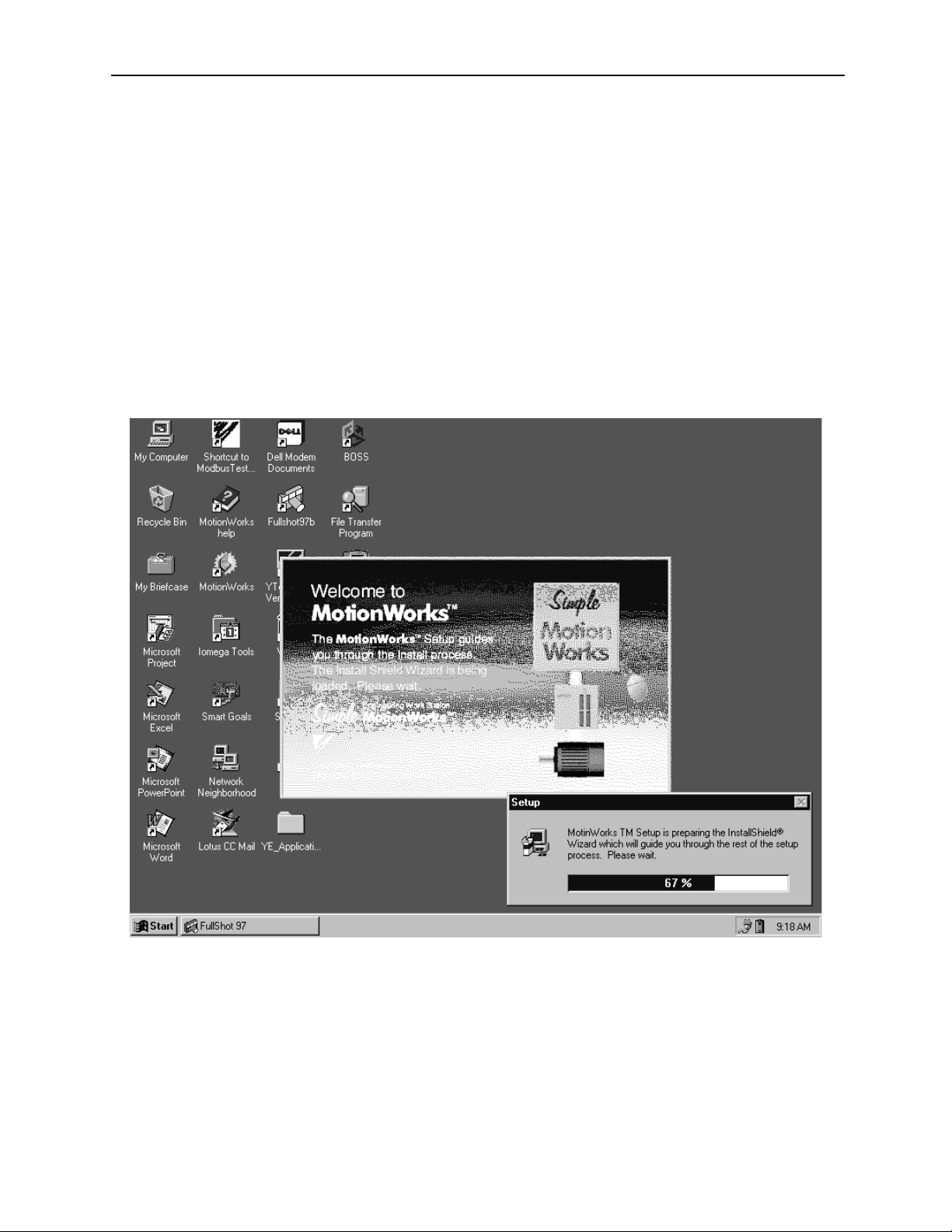
2.1.2 Set-up Preparation
The preparation screen of the set-up is shown as follows. Wait during the installation
preparation until the next screen is displayed.
2-2
Page 22

MotionSuite™ Series Machine Controller Software Manual Chapter 2: Installation
2.1.3 Starting Set-up
When the preparation is complete, the whole screen is initialized; and the installation
is started. Read the message displayed on the screen, then click the Next button to start
the set-up. The set-up can be terminated by clicking the Cancel button.
2-3
Page 23

MotionSuite™ Series Machine Controller Software Manual Chapter 2: Installation
2.1.4 User Registration
The user registration screen is displayed. Input name, company name, and serial
number.
As in item 2.1.3 above, the process moves forward when the Next button is clicked,
returns to the previous screen when the Back button is clicked; and the set-up
operation terminates when the Cancel button is clicked.
2-4
Page 24
MotionSuite™ Series Machine Controller Software Manual Chapter 2: Installation
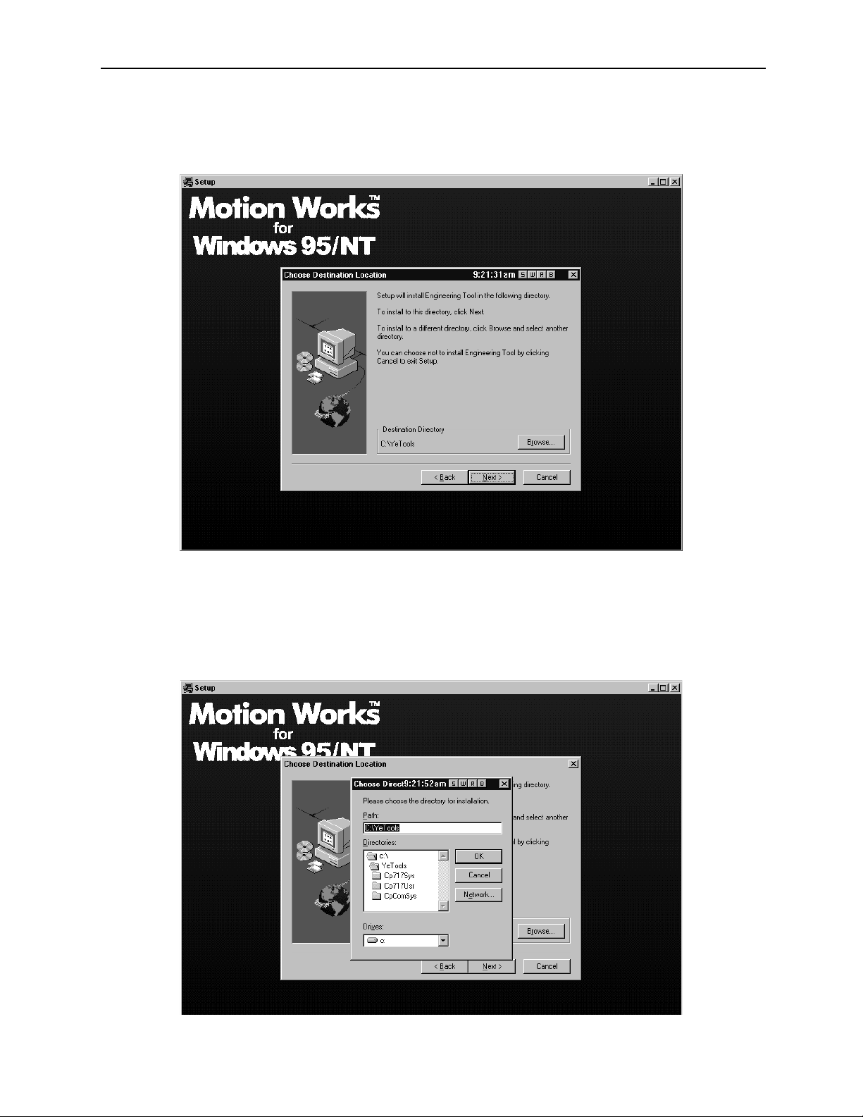
2.1.5 Selecting Destination Directory
The destination directory can either be default or chosen.
The above screen shows the installation destination directory.
C:\YeTools\ is the system default. User designation is available by clicking the
Browse button; however, using C:\YeTools\ is recommended.
When Browse is selected, the following directory selection screen is displayed. Any of
these directories can be selected.
2-5
Page 25

MotionSuite™ Series Machine Controller Software Manual Chapter 2: Installation
2.1.6 Selecting Program Folder
The program folder selection screen is shown below. Designate the program folder to
register a group of applications. It is possible to select an existing folder other than the
default, but the default “YE-Applications” is recommended.
2-6
Page 26
MotionSuite™ Series Machine Controller Software Manual Chapter 2: Installation
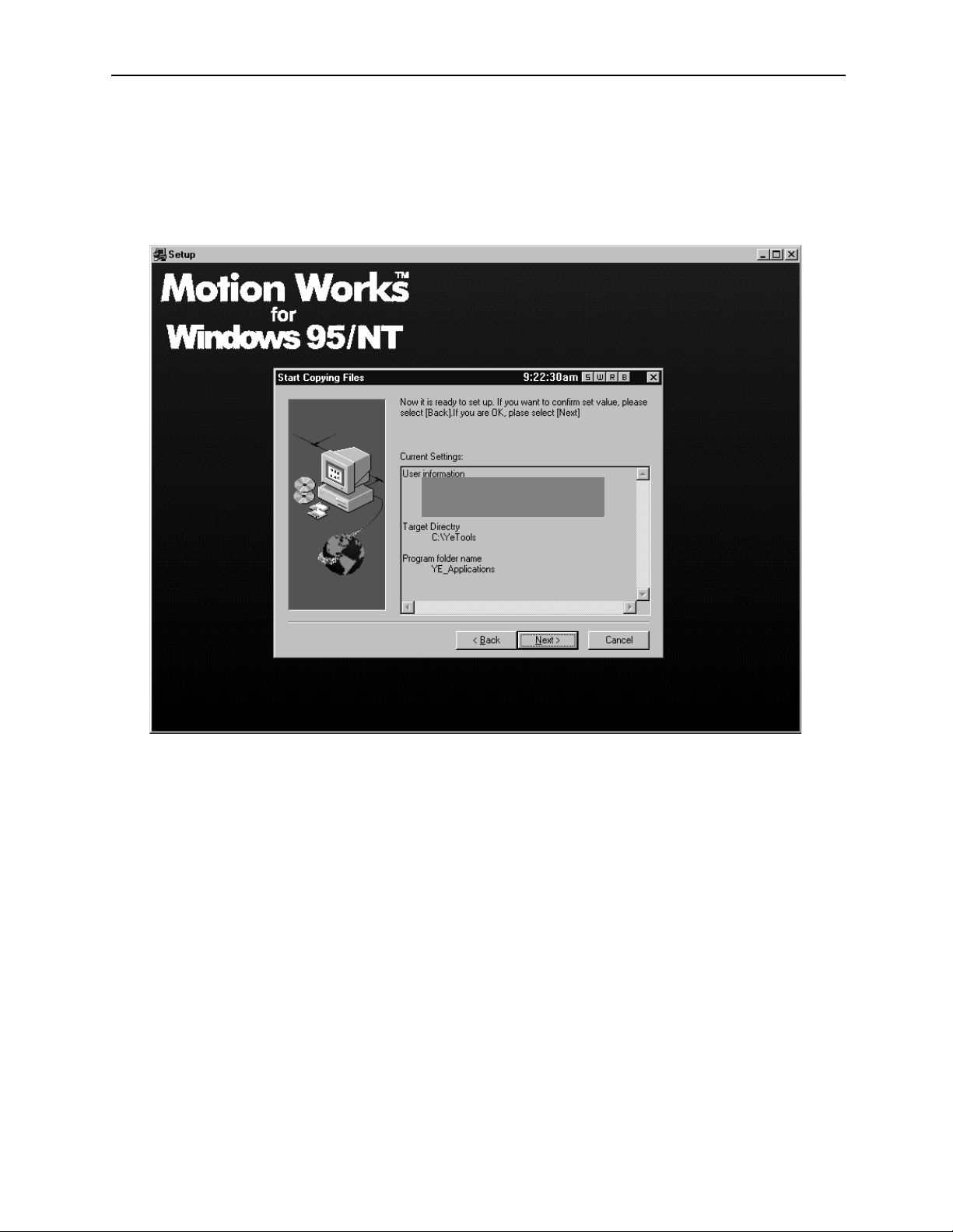
2.1.7 Modifying Input Information
The information input until now is displayed when starting to coy files. Move forward
if modification is not needed; click the Back button to return to the appropriate screen
if modification is necessary.
2-7
Page 27

MotionSuite™ Series Machine Controller Software Manual Chapter 2: Installation
2.1.8 Starting File Copy
File copying starts.
The status of the copying progress can be viewed on the bottom of the screen. Wait
until copying is complete.
2-8
Page 28
MotionSuite™ Series Machine Controller Software Manual Chapter 2: Installation
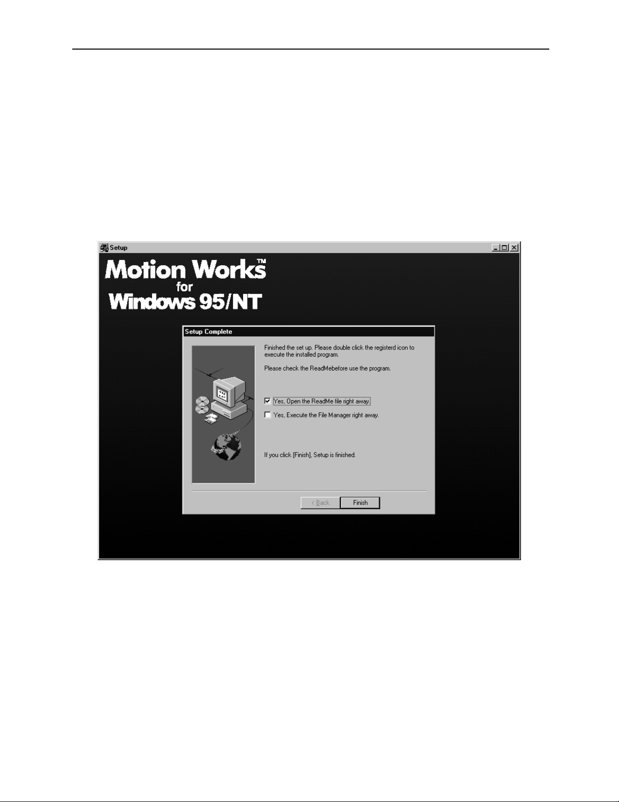
2.1.9 Completing File Copy
When copying is complete, the set-up completion screen is displayed. There are 2
check items on the screen. Choose the necessary one, then click the Finish button.
a. “Open the Readme File”
Displays the Readme file in which the updated information is written. Do not
check this item if it is not necessary.
b. “Execute the File Manager”
Starts applications after the set-up is complete.
2-9
Page 29
MotionSuite™ Series Machine Controller Software Manual Chapter 2: Installation
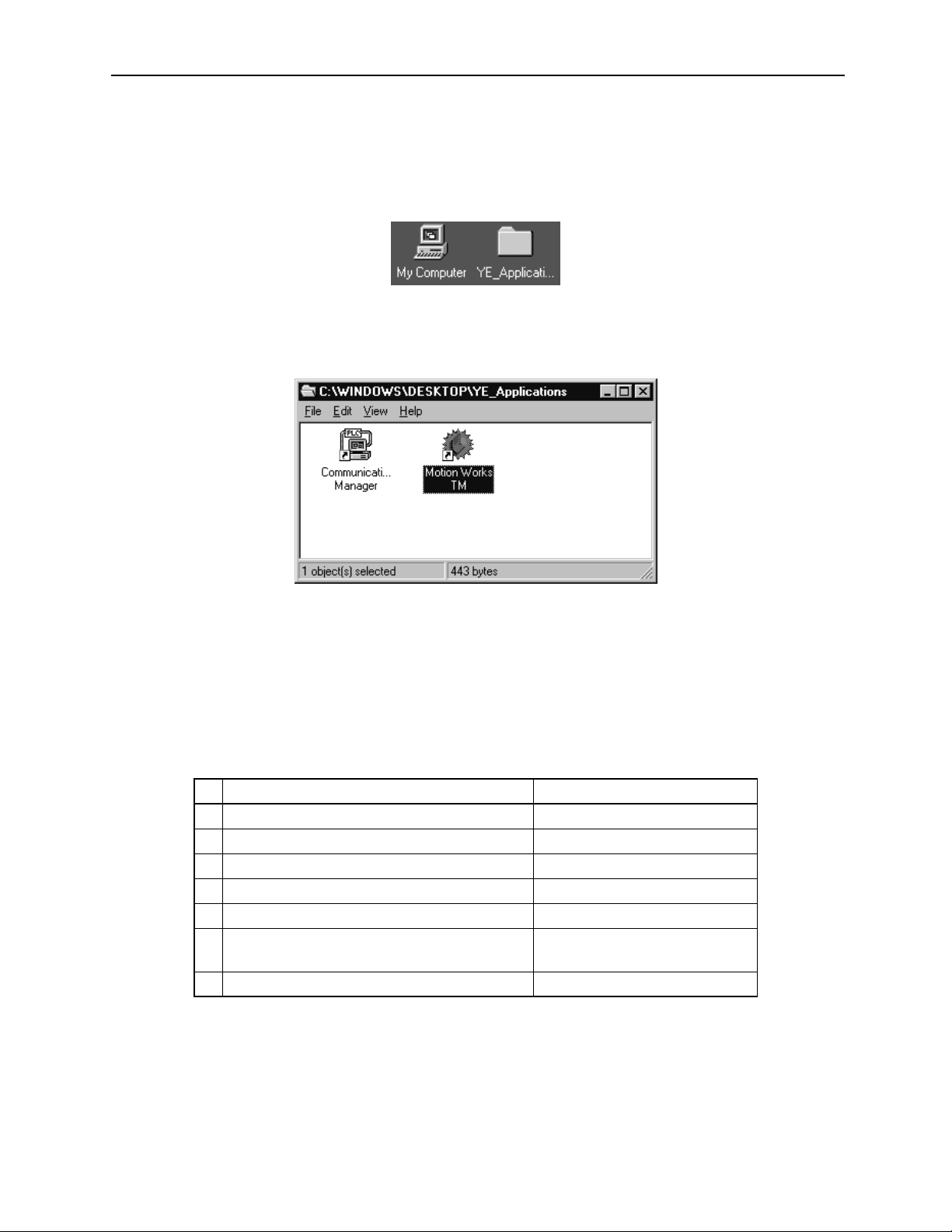
2.1.10 Completing Set-up
When the set-up is complete, the program folder (default: YE-Application), which is
the platform of the application group, is built in your PC.
When the YE-Applications program folder is clicked, the following contents are
displayed.
Click on the Start button on the lower-left corner of the screen; program menus are
displayed. The application can also be started by selecting from the menus.
2.1.11 Created Folders Upon Installing
During installation, the file corresponding to the folder created for each file
component* was copied.
File Component Created Folder
1 Readme (update information) file, etc. \...\YeTools
2 MotionWorks™ program file \...\YeTools\Cp717sys
3 MotionWorks™ data file \...\Yetools\Cp717usr
4 WindowsNT communication driver \...\WINDIR\System32\Drives
5 Windows95 communication driver \...\WINDIR\System
6 Joint DLL
7 MotionWorks™ communication program file \...\YeTools\CpComSys
* The files are divided by group according to function unit.
\...\WINDIR\system32 (NT)
\...\WINDIR\system (95)
2-10
Page 30

MotionSuite™ Series Machine Controller Software Manual Chapter 2: Installation
a. \...\YeTools
This is the most important folder because it is the base of the MotionWorks™
system. Most files are installed in this folder. The folder name can be changed,
but using this standard name is recommended.
b. \...\WINDIR
This is the folder installed in the Windows 95/NT system. It is indicated as
“\...\Windows” in the standard Windows installation. Files such as the
communication driver or joint DLL which depend on the Windows system are
installed.
2-11
Page 31

MotionSuite™ Series Machine Controller Software Manual Chapter 2: Installation
2.2 Communication Settings
This section explains how to set communication between the MotionWorks™ system and
the controller. When the installation is complete, the communication settings of the general serial ports on the MotionWorks™ side must be executed. The standard setting values
are baud rate: 19.2Kbps; data bits: 8bit; parity: even; stop bits: 1Stop bit.
Once the values are set, they are saved as the MotionWorks™ system information.
Therefore, it is not necessary to set them again unless it is needed.
MotionWorks™
.
2.2.1 Calling up Communication Manager
The communication setting is executed in the communication process. As explained in
Section 2.1: Installation Procedures, when the software installation is complete, the
communication process icon (Communication Manager) has been registered in the YeApplications program folder. Double-click to call it up.
Double-click this icon to call up the Communication Manager.
2-12
Page 32

MotionSuite™ Series Machine Controller Software Manual Chapter 2: Installation
2.2.2 Setting Communication Port
The main screen of the communication process is shown as follows. As the RS-232C
setting is the standard setting, the logical port1 is the serial.
Either double-click the logical port number, or, select a logical port, then select Set-
ting (E) from the File (F) menu.
The logical port setting screen is displayed. Select the port kind (type), then click the
Detail button.
2-13
Page 33

MotionSuite™ Series Machine Controller Software Manual Chapter 2: Installation
When the Detail button is selected, the following screen is displayed. Set up the
parameters of the serial port, then choose the OK button.
The logical port setting screen returns. Choose the OK button to return to the main
screen of the communication process. At this point, since the parameter setting is
complete, the setting contents must be saved in the file.
2.2.3 Saving Communication Port Setting Values
Save the communication port setting values to the file.
The confirmation message window is displayed when selecting Save (S) from the File
(F) menu. Choose the Ye s button to save the information.
2.2.4 Communication Process Completion
Select Exit (X) from the File (F) menu to close the communication process screen.
2-14
Page 34

MotionSuite™ Series Machine Controller Software Manual Chapter 3: Basic Operation
3 Basic Operation
This chapter explains methods of starting and closing MotionWorks™.
3.1 MotionWorks™ Basic Operation ....................................................................... 3-2
3.1.1 Basic Structural Elements of the MotionWorks™ Window ...................... 3-2
3.1.2 Keyboard and Mouse ................................................................................. 3-4
3.1.3 Cursor ......................................................................................................... 3-4
3.1.4 Title Bar ..................................................................................................... 3-5
3.1.5 Connection Information Bar ...................................................................... 3-6
3.1.6 Menu Bar ................................................................................................... 3-6
3.1.7 Window ...................................................................................................... 3-7
3.1.8 Boxes ......................................................................................................... 3-9
3.1.9 Scroll ........................................................................................................ 3-10
3.1.10 Go to Page ................................................................................................ 3-10
3.2 Shortcut Keys .................................................................................................... 3-11
3.2.1 Major Keys Generally Used in Windows ................................................ 3-11
3.2.2 Major Keys Used in Dialog Boxes .......................................................... 3-11
3.3 Starting and Closing MotionWorks™ .............................................................. 3-12
3.3.1 Starting MotionWorks™ ......................................................................... 3-12
3.3.2 Selecting Controller ................................................................................. 3-13
3.3.3 Closing MotionWorks™ .......................................................................... 3-15
3.3.4 System Shut-off ....................................................................................... 3-17
3.4 Global Menus .................................................................................................... 3-18
3.4.1 Global Menu Items .................................................................................. 3-18
3.4.2 File (F) Menu ........................................................................................... 3-19
3.4.3 View (V) Menu ........................................................................................ 3-20
3.4.4 Window (W) Menu .................................................................................. 3-21
3.4.5 Help (H) Menu ......................................................................................... 3-23
3-1
Page 35

MotionSuite™ Series Machine Controller Software Manual Chapter 3: Basic Operation
3.1 MotionWorks™ Basic Operation
In this section the basic structural elements of the MotionWorks™ window and operations
are explained using the File Manager screen.
3.1.1 Basic Structural Elements of the MotionWorks™ Window
Names and functions of the elements that compose the MotionWorks™ window are
shown as follows.
1
2
3
5
CP-717 File Manager Window
4
MotionWorks™ File Manager Window
1. Title Bar
Displays a title that represents the function of a main window or a function window.
2. Menu Bar
Displays a group of function menus. Further detailed functions can be selected in
the pull-down menus.
3. Tool Icon
Displays frequently used functions shown in the pull-down menus as icons so
that they can be performed with one click.
3-2
Page 36

MotionSuite™ Series Machine Controller Software Manual Chapter 3: Basic Operation
4. Status Bar
Displays a message from the system.
5. Cursor
Indicates the position of the mouse used to select a function or input an item.
6. Function Window
The function window is opened by selecting a function. Multiple windows can
be opened simultaneously.
6
3-3
Page 37

MotionSuite™ Series Machine Controller Software Manual Chapter 3: Basic Operation
3.1.2 Keyboard and Mouse
MotionWorks™ is operated with the keyboard and mouse.
Characters and values are input by using a combination of alphabetical characters,
numbers, punctuation marks, symbols, and control keys on the keyboard. All functions
can be selected by the function keys and shortcut keys.
The mouse determines item input position and selects function. Words frequently used
when operating the mouse are shown as follows.
Word Meaning
Click Press and quickly release a mouse button
Left-click Press and quickly release the left mouse button
Right-click Press and quickly release the right mouse button
Double-click Quickly press the left mouse button twice and quickly release it
Pointing Move the mouse cursor to the desired position then press and quickly release the
left mouse button
Drag Press and hold the left mouse button, move the object to the desired position, and
quickly release the mouse button
3.1.3 Cursor
There is a mouse cursor and a key cursor. The shape of the cursor varies according to
the operation status. General cursor shapes are shown as follows.
Cursor Type Cursor Shape Operation Status
Mouse Cursor
All functions can be selected. A window can be
moved by dragging the title bar.
These cursor shapes appear at the borders of windows,
by dragging them the size of the window can be
changed.
It appears when the cursor is at a field in a dialog box.
It appears when a window can be moved.
Key Cursor
It appears when an execution is processed.
It appears when typing data in a field of a dialog box.
It appears when typing data in a main window.
3-4
Page 38

MotionSuite™ Series Machine Controller Software Manual Chapter 3: Basic Operation
3.1.4 Title Bar
Main Window Title Bar
MotionWorks™ is composed of several independent main windows. Each main window is
further categorized into several function windows.
A function name is displayed in the title bar of each main window. MotionWorks™
includes the following main windows.
1. File Manager Window
2. Engineering Manager Window
3. Print Monitor Window
4. Print Set-up Window
5. Data Transfer Window
6. Register List Window
7. Ladder Source Convert Window
The above main windows are explained in Chapter 4 and subsequent chapters.
Function Window Title Bar
Individual function names are displayed in the title bar of function windows. Moreover,
on-line/off-line information is also shown.
123456
Part of the Function Window
1. Function Window Name
2. Group Name
3. Order Name
3-5
Page 39

MotionSuite™ Series Machine Controller Software Manual Chapter 3: Basic Operation
4. PLC Name
5. PLC Type
6. On-line/Off-line Information
3.1.5 Connection Information Bar
Information about MotionWorks™ and the MotionSuite™ series machine controller
connection is displayed in this bar. It contains a port number (PT#), a network number
(NT#), a station number (ST#), and a CPU number (CPU#). However, these numbers
do not show in off-line mode.
3.1.6 Menu Bar
The menu bar lists a group of functions. Each function (menu) can be clicked to unfold
a pull-down menu. Concrete functions are provided in this pull-down menu.
Menu items vary depending on which window is currently active (see item 3.1.7 Window). They change automatically when a different window is activated.
The above window screen shows that the File (F) menu in the Engineering Manager
window is unfolded to 3 levels. The menu item with a triangle mark at the right side
does not result in any action itself, but if a cursor is put on one of these items a group
of sub-menus appears automatically.
As shown in File (F), the letter within parentheses indicates that the menu selection
can be executed on the keyboard. By pressing the Alt key and the F key, a pull-down
menu appears in which the functions can be selected with the arrow keys on the keyboard.
In the following explanations, if File (F)→Print (P) is written, it means selecting
Print (P) from the File (F) pull-down menu. If File (F)→Open (O)→Motion Program (M)→Motion Edit (E) is written, it means selection of the Motion Edit (E)
from the sub-menu of the File (F) pull-down menu.
3-6
Page 40

MotionSuite™ Series Machine Controller Software Manual Chapter 3: Basic Operation
3.1.7 Window
A window is prepared for each function. Multiple windows can be displayed on screen
but only one can be functional, this is the active window. If a window is active, the
color of its title bar becomes darker than that of other windows.
Switching Windows
When multiple windows are displayed, activate a window by clicking anywhere in the
window.
When Motion Edit Window is Active
3-7
Page 41

MotionSuite™ Series Machine Controller Software Manual Chapter 3: Basic Operation
Switching Tabs
The tab is used to indicate a detailed function in the window. Click the tab to open the tab
window.
When Set-up Parameter Tab is Active
3-8
Page 42

MotionSuite™ Series Machine Controller Software Manual Chapter 3: Basic Operation
3.1.8 Boxes
Boxes are roughly categorized as either message boxes or dialog boxes.
Message Box
The message box appears when the system needs the user to select Ye s or No, or to con-
firm an important message.
Dialog Box
The dialog box is similar to the message box, but unlike the simple confirmation message,
the dialog box asks the user to set up more information. The set-up methods are shown as
follows.
a. Radio Button Box
The radio button box is used to select only one option. A black dot appears on a
radio button when it is selected by clicking.
b. Check Box
Unlike the radio button box, the check box is used to select more than one
option. A check mark appears in a small box at the left side of the selected item.
3-9
Page 43

MotionSuite™ Series Machine Controller Software Manual Chapter 3: Basic Operation
c. Combo-box
The combo-box is a box that contains several groups of functions. In each group,
only one option can be selected. Click the triangle mark at the right side of each
group to display all the options, then select one.
d. Edit Box (Value)
The edit box (value) is used to input a value. The value can either be input from
the keyboard or by clicking a spin button (if available) at the right side of the
box.
e. Edit Box
The edit box is used to input character strings or values from the keyboard. If
there is no cursor at the head of the box, click the box to display the cursor.
f. Press Buttons
The press buttons are used to select a simple instruction like Ye s , No or Cancel.
Click the proper button to give an instruction.
3.1.9 Scroll
It may be necessary to scroll (move) the window horizontally or vertically to view or
edit the program easily. Operate the scroll bars located at the right side and bottom of
the window to find the desired position. The window also can be scrolled using the
arrow keys on the keyboard.
3.1.10 Go to Page
Go to Page can be operated by pressing the PageUp and PageDown keys.
3-10
Page 44

MotionSuite™ Series Machine Controller Software Manual Chapter 3: Basic Operation
3.2 Shortcut Keys
In the event that the mouse cannot be used or that the user prefers to keep his/her fingers
on the keyboard, keyboard equivalents, or shortcuts, are available. In this section, several
shortcut keys used in MotionWorks™ are explained.
3.2.1 Major Keys Generally Used in Windows
Purpose Shortcut Key
Displays start menu Ctrl+Esc
Close program window Alt+F4
Switch selected program Alt+Tab
Switch program by order Alt+Esc
Switch program by reverse order Shift+Alt+Esc
Cut Ctrl+X
Copy Ctrl+C
Paste Ctrl+V
Delete Del
Return Ctrl+Z
Switch sub-drawing window Ctrl+F6
3.2.2 Major Keys Used in Dialog Boxes
Purpose Shortcut Key
OK button Enter
Cancel button Esc
Switch tab by order Tab
Switch tab by reverse order Shift+Tab
Switch tab page by order Ctrl+Tab
Switch tab page by reverse order Shift+Ctrl+Tab
Switch check box on/off Space
Switch radio button selection Arrow keys
Switch list box or combo-box selection Arrow keys
Switch press button Arrow keys
3-11
Page 45

MotionSuite™ Series Machine Controller Software Manual Chapter 3: Basic Operation
3.3 Starting and Closing MotionWorks™
3.3.1 Starting MotionWorks™
a. Plug in the PC to start Windows95.
b. Double-click the YE-Applications icon.
c. Double-click MotionWorks™ in the YE-Applications group to start the
MotionSuite™ series machine controller File Manager Window.
d. The MotionWorks™ File Manager Window (main screen of MotionWorks™)
is displayed.
3-12
Page 46

MotionSuite™ Series Machine Controller Software Manual Chapter 3: Basic Operation
The File Manager Window and the Communication Process window start
simultaneously, as shown in the task bar.
3.3.2 Selecting Controller
The File Manager screen is the starting point for all MotionWorks™ operations. The
controller (in which programs are created and data is defined) must be selected first so
that the MotionWorks™ functions can be performed. In this section, simple selection
procedures are described; detailed operation methods are dealt with later.
As shown in the above window screen, double-click the root, the group folder, and the
order folder to unfold the system structure. The system structure can also be unfolded
by clicking the
“+” symbol at the left side of the folder.
When the order folder is opened, the controller name is shown as follows:
The icon at the front of the name differs from others so that it is easily distinguishable.
3-13
Page 47

MotionSuite™ Series Machine Controller Software Manual Chapter 3: Basic Operation
Log-in
The MotionSuite™ series machine controller must be logged in so that it can be controlled
by MotionWorks™.
Before log in, right-click the controller folder to open a pop-up menu. In the pop-up menu,
on-line/off-line mode can be switched by clicking.
When a check mark appears before the on-line menu, the on-line mode is active. When no
check mark appears, the controller is in off-line mode.
When the log-in is complete, the “+” symbol appears at the left side of the icon, as shown
below.
System Protection through New User Registration
When the controller is logged in, a security dialog box appears as follows:
It is necessary to limit the users who can log in to the controller in order to protect the system when a program is running. MotionWorks™ protects the system by inputting the user
name and a password.
User Management provides the User Privilege Level in addition to the New User Registration and Existing User Deletion. Details are explained later.
3-14
Page 48

MotionSuite™ Series Machine Controller Software Manual Chapter 3: Basic Operation
a. Inputting User Name
Input the user name with 8 characters or less.
b. Inputting Password
The password is input with 16 characters or less. The input characters are displayed as a symbol string of “*” for security purposes. The system allows input
of the password up to three times; if the number of attempts exceeds three times,
the log-in operation is cancelled.
When first logging in, use the default user name and password determined by the
system (see User Management).
Log-off
It is advisable to log off when a series of operations are complete, to avoid control of the
MotionSuite™ series machine controller by unauthorized personnel. Log in again when
needed. Log-in and log-off must be used as a pair.
Right-click the controller folder to open a pop-up menu, then click log-off as indicated
below.
When the log-off is complete, all items unfolded in the folder close. The log-in symbol
(“+”) at the left side of the icon is also gone.
3.3.3 Closing MotionWorks™
Close MotionWorks™ after logging off the MotionSuite™ series machine controller.
The windows other than the File Manager screen also must be closed because it is not
possible to close MotionWorks™ while these windows are open.
3-15
Page 49

MotionSuite™ Series Machine Controller Software Manual Chapter 3: Basic Operation
a. Closing the File Manager Window
Click Exit (X) from File (F) in the File Manager menu.
Or, click the X mark at the upper right corner in the File Manager window.
b. Closing the Communication Process Window
Right-click the Communication Process button on the task bar to open a pop-up
menu, then click the Close item.
When Close is clicked, a message box appears. Ensure that you really want to terminate communication, then choose the Ye s button.
3-16
Page 50

MotionSuite™ Series Machine Controller Software Manual Chapter 3: Basic Operation
3.3.4 System Shut-off
It is necessary to close Windows95 before shutting off the power supply. Click the
Start button on the task bar to open a pop-up menu, then select the Shut Down item.
When Windows95 is properly closed, the following message appears: It is now safe to
turn off your computer. The power supply can be shut off in this condition. In some
PCs the power supply shuts off automatically, depending on the configuration.
3-17
Page 51

MotionSuite™ Series Machine Controller Software Manual Chapter 3: Basic Operation
3.4 Global Menus
This section explains the menus and menu items that apply to every window.
3.4.1 Global Menu Items
The pull-down menu items in the File (F), View (V), Window (W), and Help (H)
menus apply to every MotionWorks™ window. They are shown as follows.
Menu Global Function
File (F)
File Manager (F) Displays the File Manager Window
Open (O)
Close (C)
Save (S)
Delete (D)
Print (P) Prints documents
Exit (X) Close window
(See menu explanation of each screen)
Vie w ( V)
Tool Bar (T) Displays tool bar
Status bar (S) Displays status bar
Window (W)
Cascade (C) Cascades window displays
Tile (T) Tiles window displays
Arrange Icons (A) Lines up all icons
Help (H)
Help Topics (H) Search Help topic
About Application (A) Displays version information
(See menu explanation of each screen)
3-18
Page 52

MotionSuite™ Series Machine Controller Software Manual Chapter 3: Basic Operation
3.4.2 File (F) Menu
File Manager (F)
The File Manager (F) is displayed in the forefront screen when it is selected from the File
(F) menu.
Print (P)
A Print Set-up Window is displayed when Print Program (P) is selected from the File (F)
menu. Set up the print data and format to print. (Refer to Chapter 12: Print.)
3-19
Page 53

MotionSuite™ Series Machine Controller Software Manual Chapter 3: Basic Operation
Exit (X)
The Engineering Manager window (key window opened from the File Manager) and other
windows can be closed when Exit (X) is selected from the File (F) menu.
If this operation is performed in the File Manager Window, the File Manager Window is
also closed.
3.4.3 View (V) Menu
Switching Tool Bar Display
The Display/Hide function of the tool bar can be switched by selecting Tool Bar (T) from
the View (V) menu.
Tool Bar Function
Tool Icon Function
Moves one level up from the current existing folder
Deletes selected folder
Displays property of a selected folder or file
Displays file names with large or small icons respectively
Displays file data with list or detail displays
Displays version information
Displays Help information
Opens a newly created program file
Opens an already existing program file
Displays Print Set-up window
Editing tools (Cut, Copy, and Paste)
3-20
Page 54

MotionSuite™ Series Machine Controller Software Manual Chapter 3: Basic Operation
Switching Status Bar Display
The Display/Hide function of the Status Bar located on the bottom line of the window can
be toggled.
3.4.4 Window (W) Menu
Cascade Display
When Cascade (C) is selected from the Window (W) menu, window screens lie one upon
another tidily from the upper left corner.
3-21
Page 55

MotionSuite™ Series Machine Controller Software Manual Chapter 3: Basic Operation
Tile (T) Display
When Tile (T) is selected from the Window (W) menu, window screens line up tidily
from the top.
Arrange Icons
When Arrange Icons (A) is selected from the Window (W) menu, properly miniaturized
icons are tidily displayed on the task bar.
3-22
Page 56

MotionSuite™ Series Machine Controller Software Manual Chapter 3: Basic Operation
3.4.5 Help (H) Menu
Help Topics
Displays Help topics
About Application
The MotionWorks™ system version information can be displayed from the File Manager
menu and the Engineering Manager menu.
a. The version information is displayed from the File Manager menu as shown
below. The screen appears when About Application (A) is selected from the
Help (H) menu. It can be closed by choosing the OK button.
3-23
Page 57

MotionSuite™ Series Machine Controller Software Manual Chapter 3: Basic Operation
b. The version information is displayed from the Engineering Manager menu as
shown below. This screen appears when the About Application (A) is selected
from the Help (H) menu. It can be closed by choosing the OK button.
3-24
Page 58

MotionSuite™ Series Machine Controller Software Manual Chapter 4: File Manager
4 File Manager
File Manager provides the file management function which is the starting
point of the MotionWorks™ system.
This chapter explains how to manage the program file, definition file, etc.
used in the MotionWorks™ system.
4.1 Window Configuration ....................................................................................... 4-3
4.1.1 Folder and File Names ............................................................................... 4-4
4.1.2 File Manager Menu .................................................................................... 4-5
4.1.3 Global Menus ............................................................................................. 4-7
4.1.4 Menus for the Root and Group Folders ..................................................... 4-8
4.1.5 Menus for the Order Folder ....................................................................... 4-9
4.1.6 Menus for the Controller .......................................................................... 4-10
4.1.7 Menus for Program, Definition, and Table Data Folder .......................... 4-11
4.1.8 Menus for Interrupt DWG, Function, High Scan, Starting DWG,
and Low Scan Folder ............................................................................... 4-12
4.1.9 Menus for Program File ........................................................................... 4-14
4.1.10 Menus for Motion Folder ......................................................................... 4-16
4.1.11 Menus for Motion Group Folder ............................................................. 4-17
4.1.12 Menus for Motion Program File .............................................................. 4-18
4.1.13 Menus for Group Definition and Motion Parameter File ........................ 4-19
4.1.14 Tree-like Display Window ....................................................................... 4-20
4.1.15 List Display Window ............................................................................... 4-22
4.1.16 Detail Display Window ........................................................................... 4-26
4.2 Rename ............................................................................................................. 4-29
4.3 New Controller Registration ............................................................................. 4-31
4.3.1 Creating New Group Folder .................................................................... 4-31
4.3.2 Creating New Order Folder ..................................................................... 4-32
4.3.3 Creating New Controller Folder .............................................................. 4-34
4.4 Changing Controller Configuration .................................................................. 4-39
4.5 Deleting Folder or File ...................................................................................... 4-43
4.6 CPU Log-on/Log-off ........................................................................................ 4-45
4.6.1 Logging on to the CPU ............................................................................ 4-45
4.6.2 Logging off from the CPU ....................................................................... 4-46
4.7 Switching On-line/Off-line Mode ..................................................................... 4-48
4.8 Switching CPU Status ....................................................................................... 4-50
4.9 Editing DWG/Function Program ...................................................................... 4-52
4-1
Page 59

MotionSuite™ Series Machine Controller Software Manual Chapter 4: File Manager
4.9.1 Copying Program ..................................................................................... 4-52
4.9.2 Setting Disable ......................................................................................... 4-53
4.9.3 Switching Sub-program Unit Display ...................................................... 4-54
4.10 Updating Information ...................................................................................... 4-55
4.11 File Operation of the Motion Program ............................................................. 4-56
4.11.1 Copying Program ..................................................................................... 4-56
4.12 User Management ............................................................................................. 4-57
4.12.1 Registering A New User .......................................................................... 4-58
4.12.2 Changing User Information ..................................................................... 4-60
4.12.3 Deleting User ........................................................................................... 4-61
4.12.4 Saving User Manager Data ...................................................................... 4-62
4.12.5 Setting Default User ................................................................................. 4-62
4.13 File Transfer ...................................................................................................... 4-64
4.13.1 Opening File Transfer Window ............................................................... 4-64
4.13.2 All Transfer .............................................................................................. 4-65
4.13.3 Individual Transfer .................................................................................. 4-75
4.13.4 Changing Transfer Source and Transfer Destination .............................. 4-78
4.13.5 Setting Detailed Data ............................................................................... 4-78
4.13.6 Starting Transfer ...................................................................................... 4-79
4.13.7 Continuous Transfer ................................................................................ 4-80
4.13.8 Closing File Transfer Window ................................................................ 4-81
4-2
Page 60

MotionSuite™ Series Machine Controller Software Manual Chapter 4: File Manager
4.1 Window Configuration
Upon starting the MotionWorks™ system (see Item 3.3.1 “Starting MotionWorks™”), the
first window that appears is the File Manager Window. All MotionWorks™ operations
start from this window. The File Manager Window is composed of Tree-like Display
Window, List Display Window, and Detail Display Window. This configuration helps
users to easily and quickly understand the system structure.
List Display Window
Detail Display Window Tree-like Display Window
File Manager Window
In the Tree-like Display Window, all folders and files that construct the system are shown.
The List Display Window displays all files included in the selected folder of the Tree-like
Display Window. This selected folder is also detailed in the Detail Display Window.
4-3
Page 61

MotionSuite™ Series Machine Controller Software Manual Chapter 4: File Manager
4.1.1 Folder and File Names
The folders and files that comprise the MotionWorks™ system are shown with icons
in the Tree-like Display Window. They are named as follows.
(root) folder
Group folder
Order (Customer) folder
PLC folder
Definition folder
Program folder
Function folder
High Scan DWG folder
Program file
Motion folder
Group Definition file
Motion Group folder
Tree-like Display Window
Motion Program file
Motion Parameter file
Interrupt DWG folder
Low Scan DWG folder
Starting DWG folder
Table Data folder
4-4
Page 62

MotionSuite™ Series Machine Controller Software Manual Chapter 4: File Manager
4.1.2 File Manager Menu
There are pull-down menus and pop-up menus in the File Manager menu. The menu
contents vary according to the folder or file selected in the Tree-like Display Window
or the List Display Window.
Pop-up Menu
The pop-up menu appears after a right-click on a menu. Each menu item in the pop-up
menu can be selected. The following example shows that the pop-up menu is opened when
a Motion folder is selected.
Pop-up Menu
4-5
Page 63

MotionSuite™ Series Machine Controller Software Manual Chapter 4: File Manager
Pull-down Menu
The Menu bar of the File Manager Window is shown above. From File (F) to Help (H),
the name of each menu does not change, but the contents of the pull-down menus unfolded
from each menu vary according to the folder or file selected in the Tree-like Display
Window or the List Display Window. For example, when a Group folder or a controller is
selected, the File (F) menu shows the following different contents.
When a Group folder is selected
When a controller is selected
The Items 4.1.4 ~ 4.1.13 show how the pull-down menus and pop-up menus change
according to the different folders or files.
4-6
Page 64

MotionSuite™ Series Machine Controller Software Manual Chapter 4: File Manager
4.1.3 Global Menus
No matter which folder or file is selected in the Tree-like Display Window, some
menus such as File (F)→Transfer (T), View (V), Tool (T), and Help (H) always
show the same items. These menus are called global menus.
File (F)→Transfer (T), View (V), Tool (T), and Help (H) are unfolded to the following global sub-menus. However, some exceptions exist and they are explained in
detail.
Menu Function Reference
Transfer (T)
All Transfer (A) Transfers files one after the other —
Individual Transfer (I) Transfers file individually —
Continuous Transfer (C) Transfers file to multiple controllers —
Menu Function Reference
Vie w ( V)
Tool Bar (T) Displays tool bar —
Status Bar (S) Displays status bar —
Detail Window (W) Displays or hides the Detail Display Window —
Large Icon (G) Displays file with large icon —
Small Icon (M) Displays file with small icon —
List (L) Lists file with small icon —
Detail (D) Lists detailed data —
Refresh (R) Displays updated information —
Menu Function Reference
Too l (T)
Register List (R) Displays register list —
Menu Function Reference
Help (H)
About App. (A) Displays version information —
4-7
Page 65

MotionSuite™ Series Machine Controller Software Manual Chapter 4: File Manager
4.1.4 Menus for the Root and Group Folders
When the (root) or the Group folder is selected, the pull-down menu and the pop-up
menu are shown as follows.
Table 4.1: Pull-down Menu
Menu Functions Reference
File (F)
New (N)
Group folder (G) Creates new group folder —
Order folder (O) Creates new order folder —
Delete (D) Deletes folder or file —
Rename (M) Changes folder or file name —
Exit (X) Exits from application creation —
Edit (E)
Default User Set (D) Sets up default user —
Vie w ( V)
Too l (T)
Help (H)
Table 4.2: Pop-up Menu
Menu Functions Reference
New (N)
Group folder (G) Creates new group folder —
Order folder (O) Creates new order folder —
Rename (M) Changes folder or file name —
Delete (D) Deletes folder or file —
4-8
Page 66

MotionSuite™ Series Machine Controller Software Manual Chapter 4: File Manager
4.1.5 Menus for the Order Folder
When the Order folder is selected, the pull-down menu and the pop-up menu are
shown as follows.
Table 4.3: Pull-down Menu
Menu Functions Reference
File (F)
New (N)
Controller folder (C) Creates new PLC folder —
Delete (D) Deletes folder or file —
Rename (M) Changes folder or file name —
Exit (X) Exits from application creation —
Edit (E)
Default User Set (D) Sets up default user —
Vie w ( V)
Too l (T)
Help (H)
Table 4.4: Pop-up Menu
Menu Functions Reference
New Make (N)
Controller folder (C) Creates new controller folder —
Rename (M) Changes folder or file name —
Delete (D) Deletes folder or file —
4-9
Page 67

MotionSuite™ Series Machine Controller Software Manual Chapter 4: File Manager
4.1.6 Menus for the Controller
When the controller is selected, the pull-down menu and the pop-up menu are shown
as follows.
Table 4.5: Pull-down Menu
Menu Functions Reference
File (F)
Log-on (G) Logs on CPU —
Delete (D) Deletes folder or file —
Property (R) Changes controller configuration —
Log-off (U) Logs off from CPU —
File transfer (T) Transfers file —
Print (P) Prints document —
Exit (X) Exits from application creation —
Edit (E)
Default User Set (D) Sets up default user —
User Manager (U) Manages user —
CPU Control (C) Switches CPU status —
View ( V)
Tool (T)
Register List (R) Displays register list —
Help (H)
Table 4.6: Pop-up Menu
Menu Function Reference
On-line (O) Switches on-line or off-line mode —
Log-on (G) Logs on CPU —
Property (R) Changes PLC configuration —
File transfer (T) Transfers file —
Delete (D) Deletes folder or file —
CPU control (C) Changes CPU status —
Log-off (U) Logs off from CPU —
4-10
Page 68

MotionSuite™ Series Machine Controller Software Manual Chapter 4: File Manager
4.1.7 Menus for Program, Definition, and Table Data Folder
When the Program, the Definition, or the Table Data folder is selected, the pull-down
menu and the pop-up menu are shown as follows.
Table 4.7: Pull-down Menu
Menu Function Reference
File (F)
Log-off (U) Logs off from CPU —
Transfer (T) Transfers file —
Print (P) Prints document —
Exit (X) Exits from application creation —
Edit (E)
Default User Set (D) Sets up default user —
User Manager (U) Manages user —
CPU Control (C) Changes CPU status —
Vie w ( V)
Too l (T)
Help (H)
Table 4.8: Pop-up Menu
Menu Function Reference
Transfer (T) Transfers file —
CPU Control (C) Changes CPU status —
Log-off (U) Logs off from CPU —
4-11
Page 69

MotionSuite™ Series Machine Controller Software Manual Chapter 4: File Manager
4.1.8 Menus for Interrupt DWG, Function, High Scan, Starting DWG,
and Low Scan Folder
When the Interrupt DWG, Function, High Scan, Starting DWG, or the Low Scan
Folder is selected, the pull-down menu and the pop-up menu are shown as follows.
.
Table 4.9: Pull-down Menu
Menu Function Reference
File (F)
New Make Folder (N) Opens new drawing —
Property (R) Changes PLC configuration —
Log-off (U) Logs off from CPU —
Print (P) Prints document —
Exit (X) Exits from application creation —
Edit (E)
Default User Set (D) Sets up default user —
User Manager (U) Manages user —
Vie w ( V)
List display (V)
Display All DWG (A)
SFC Flowchart (S) —
Constant Table (#Register) (#) —
Constant Table (M register) (M) —
Input/Output Convert Table (O) —
Interlock Table (I) —
Part Assembly Table (A) —
Tuning Panel (P) —
Function Block Diagram (F) —
Tool Bar (T) Displays tool bar —
Status Bar (S) Displays status bar —
Detail Window (W) Displays or hides the detail display window —
Large Icon (G) Displays file with large icon —
Small Icon (M) Displays file with small icon —
List (L) Lists file with small icon —
Detail (D) Lists detailed data —
Refresh (R) Displays updated information —
Too l (T)
Help (H)
Displays a sub-program
—
4-12
Page 70

MotionSuite™ Series Machine Controller Software Manual Chapter 4: File Manager
Table 4.10: Pop-up Menu
Menu Function Reference
Make New DWG (N) Opens new drawing —
List Display (V)
Display All DWG (A)
Sequential Function Chart (S)
Constant Table (#Register) (#)
Constant Table (M register) (M)
Input/Output Convert Table (O)
Interlock Table (I)
Part Assembly Table (A)
Tuning Panel (P)
Function Block Diagram (F)
Displays a sub-program —
4-13
Page 71

MotionSuite™ Series Machine Controller Software Manual Chapter 4: File Manager
4.1.9 Menus for Program File
When the Program file is selected, the pull-down menu and the pop-up menu are
shown as follows.
Table 4.11: Pull-down Menu
Menu Function Reference
File (F)
Make New Folder (N) Opens new drawing —
Open (O)
DWG Property (R) Opens property window —
Main Program (N) Opens main program window —
Sequential Function Chart (S) Opens sequential function chart window —
Constant Table (#Register) (#) Opens constant table (#Register) window —
Constant Table (M Register) (M) Opens constant table (M register) window —
Input/Output Convert Table (O) Opens input/output convert table window —
Interlock Table (I) Opens interlock table window —
Part Assembly Table (A) Opens part assembly table window —
Tuning Panel (T) Opens tuning panel window —
Function Block Diagram (F) Opens function block diagram window —
Delete (D) Deletes new program —
Property (P) Not used —
Log-off (U) Logs off from CPU —
Print (P) Prints document —
Exit (X) Exits from application creation —
Edit (E)
Default User Set-up (D) Sets up default user —
User Manager (U) Manages user —
Enable/Disable (E) Sets up new program disable —
View (D )
List Display (V)
Display All (A)
SFC Flowchart (S)
Constant Table (#Register) (#)
Constant Table (M Register) (M)
Input/Output Convert Table (O)
Interlock Table (I)
Part Assembly Table (A)
Tuning Panel (P)
Function Block Diagram (F)
Tool Bar (T) Displays tool bar —
Status Bar (S) Displays status bar —
Detail Window (W) Displays or hides the Detail Display Window —
Large Icon (G) Displays file with large icon —
Small Icon (M) Displays file with small icon —
List (L) Lists file with small icon —
Detail (D) Lists detailed data —
Refresh (R) Displays updated information —
Tool (T)
Help (H)
Displays sub-program unit —
4-14
Page 72

MotionSuite™ Series Machine Controller Software Manual Chapter 4: File Manager
Table 4.12: Pop-up Menu
Menu Function Reference
File (F)
Make New DWG (N) Opens new program —
Open (O)
DWG Property (R) Opens property window —
Main Program (N) Opens main program window —
Sequential Function Chart (S) Opens sequential function chart window —
Constant Table (#Register) (#) Opens constant table (#Register) window —
Constant Table (M register) (M) Opens constant table (M register) window —
Input/Output Convert Table (O) Opens input/output convert table window —
Interlock Table (I) Opens interlock table window —
Part Assembly Table (A) Opens part assembly table window —
Tuning Panel (P) Opens tuning panel window —
Function Block Diagram (F) Opens function block diagram window —
List Display (V)
Display All DWG (A)
Sequential Function Chart (S)
Constant Table (#Register) (#)
Constant Table (M register) (M)
Input/Output Convert Table (O)
Interlock Table (I)
Part Assembly Table (A)
Tuning Panel (P)
Function Block Diagram (F)
Delete DWG (D) Deletes program —
Enable/Disable (E) Sets up new program disable —
Copy DWG (C) Copies program —
Displays sub-program unit —
4-15
Page 73

MotionSuite™ Series Machine Controller Software Manual Chapter 4: File Manager
4.1.10 Menus for Motion Folder
When the Motion Folder is selected, the pull-down menu and the pop-up menu are
shown as follows.
.
Table 4.13: Pull-down Menu
Menu Function Reference
File (F)
Open (O)
Group Definition (G) Defines Group information —
Motion Parameter (P) Defines and displays Motion parameter —
Motion Editor (E) Edits Motion program —
Position Monitor (P) Displays current position —
Motion Alarm (A) Displays alarm information —
Log-off (U) Logs off from CPU —
Transfer (T)
Print (P) Prints document —
Exit Exits from application creation —
Edit (E)
Default User Set (D) Sets up default user —
User Manager (U) Manages user —
CPU Control (C) Changes CPU status —
Vie w ( V)
Too l (T)
Help (H)
Table 4.14: Pop-up Menu
Menu Function Reference
Open (O)
Group Definition (G) Defines Group information —
Motion Parameter (P) Defines and displays Motion parameter —
Motion Editor (E) Edits Motion program —
Position Monitor (P) Displays current position —
Motion Alarm (A) Displays alarm information —
Transfer (T)
CPU control (C) Changes CPU status —
Log-off (U) Logs off from CPU —
4-16
Page 74

MotionSuite™ Series Machine Controller Software Manual Chapter 4: File Manager
4.1.11 Menus for Motion Group Folder
When the Motion Group folder is selected, the pull-down menu and the pop-up menu
are shown as follows.
.
Table 4.15: Pull-down Menu
Menu Function Reference
File (F)
Make New Program (N)
Open (O)
Motion Editor (E) Edits Motion program —
Position Monitor (P) Displays current position —
Motion Alarm (A) Displays alarm information —
Log-off (U) Logs off from CPU —
Print (P) Prints document —
Exit (X) Exits from application creation —
Edit (E)
Default User Set (D) Sets up default user —
User Manager (U) Manages user —
Vie w ( V)
Too l (T)
Help (H)
Table 4.16: Pop-up Menu
Menu Function Reference
Make New Program (N)
Open (O)
Motion Editor (E) Edits Motion program —
Position Monitor (O) Displays current position —
Motion Alarm (A) Displays alarm information —
4-17
Page 75

MotionSuite™ Series Machine Controller Software Manual Chapter 4: File Manager
4.1.12 Menus for Motion Program File
When the Motion Program file is selected, the pull-down menu and the pop-up menu
are shown as follows.
.
Table 4.17: Pull-down Menu
Menu Function Reference
File (F)
Make New Program (N)
Open (O)
Motion Editor (E) Edits Motion program —
Position Monitor (O) Displays current position —
Motion Alarm (A) Displays alarm information —
Delete (D) Deletes Motion program file —
Property (P) Not used —
Log-off (U) Logs off from CPU —
Print (P) Prints document —
Exit (X) Exits from application creation —
Edit (E)
Default User Set (D) Sets up default user —
User Manager (U) Manages user —
Vie w ( V)
Too l (T)
Help (H)
Table 4.18: Pop-up Menu
Menu Function Reference
Make New Program (N)
Open (O)
Motion Editor (E) Edits Motion program —
Position Monitor (P) Displays current position —
Motion Alarm (A) Displays alarm information —
Delete DWG (D) Deletes Motion program file —
Copy DWG (C) Copies Motion program file —
4-18
Page 76

MotionSuite™ Series Machine Controller Software Manual Chapter 4: File Manager
4.1.13 Menus for Group Definition and Motion Parameter File
When the Group Definition or the Motion Parameter file is selected, the pull-down
menu and the pop-up menu are shown as follows.
.
Table 4.19: Pull-down Menu
Menu Function Reference
File (F)
Log off (U) Logs off from CPU —
Transfer (T) Transfers file —
Print (P) Prints document —
Exit (X) Exits from application creation —
Edit (E)
Default user set (D) Sets up default user —
User manager (U) Manages user —
CPU control (C) Changes CPU status —
Vie w ( V)
Too l (T)
Help (H)
Table 4.20: Pop-up Menu
Menu Function Reference
Transfer (T) Transfers file —
CPU control (C) Changes CPU status —
Log-off (U) Logs off from CPU —
4-19
Page 77
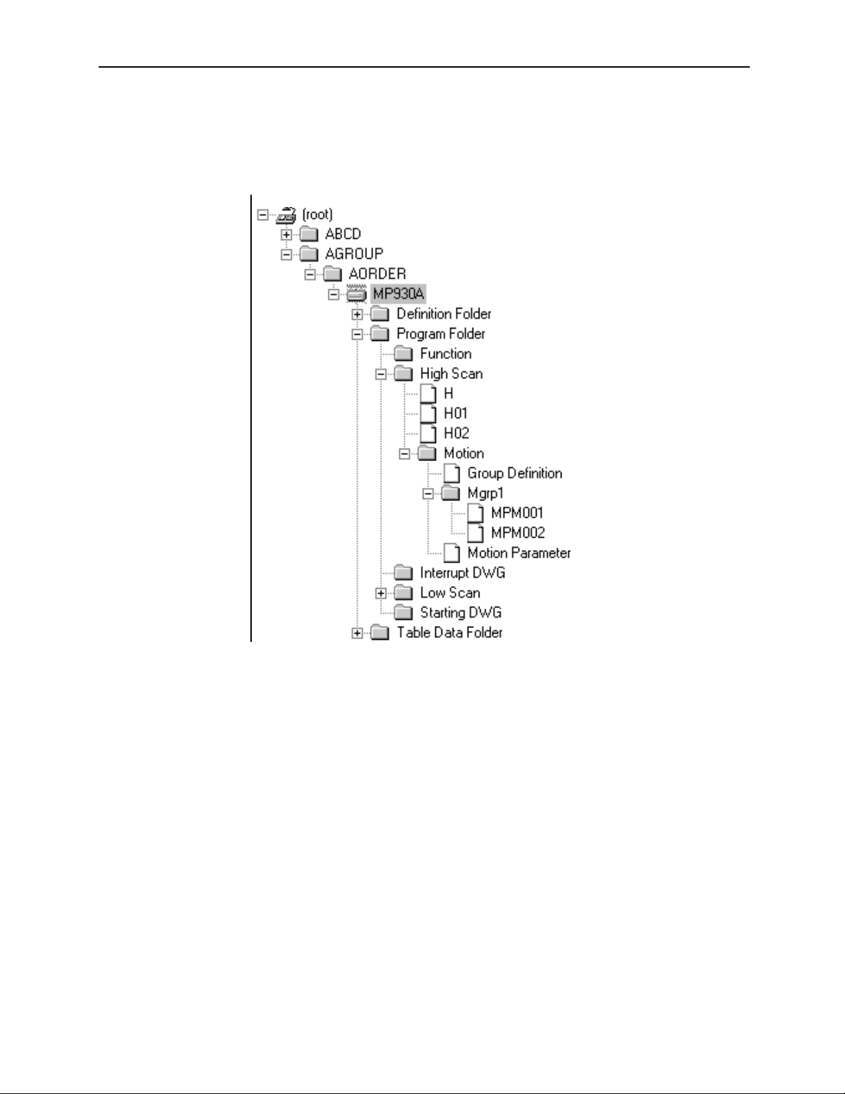
MotionSuite™ Series Machine Controller Software Manual Chapter 4: File Manager
4.1.14 Tree-like Display Window
The system structure is unfolded. The programs and definition data saved in the
system are shown with the Group names and the Order names like a tree structure.
These programs and definition data are saved on the hard disk in off-line mode and
saved in the controller in on-line mode.
4-20
Page 78

MotionSuite™ Series Machine Controller Software Manual Chapter 4: File Manager
Folder Display
A small symbol at the left side of an icon indicates that more menus can be unfolded.
This symbol indicates that the folder is closed. It changes to “-” by clicking, and the folder
+
contents are displayed. This operation also can be done by double-clicking the folder name.
This symbol indicates that the folder is open. It changes to “+” by clicking, and the folder contents
are closed. This operation also can be done by double-clicking the folder name.
Folder Icon
The folder type can be distinguished by the following icons.
Root folder (installed with the system) represents
:
the starting point of the Tree-like Display Window
Group folder (Group name)
Order folder (Customer name)
Tag folder
Program folder
Interrupt DWG folder
Function folder
Starting DWG folder
:
High Scan folder
Low Scan folder
Definition folder
Table Data folder
Motion folder
Motion Group folder
: Controller
:CPU folder
: File (program, definition data etc.)
4-21
Page 79

MotionSuite™ Series Machine Controller Software Manual Chapter 4: File Manager
4.1.15 List Display Window
The folders or files included in the folder selected in the Tree-like Display Window are
shown in the List Display Window. The contents shown in this window vary according
to the folder selected in the Tree-like Display Window.
When the Root or Group Folder is Selected
12
Titles of the List Display Window
1. File Name
Group or Order folder name is displayed.
2. File Type
Folder type is displayed.
When the Order (Customer) Folder is Selected
123 4 5 76 8
Titles of the List Display Window
1. File Name
Folder name is displayed.
2. File Type
Folder type is displayed.
3. PLC Type
PLC or CPU type is displayed.
4. On-line Mode
Zero (0) is displayed in on-line mode.
5. Database
This data is invalid in the current version.
4-22
Page 80

MotionSuite™ Series Machine Controller Software Manual Chapter 4: File Manager
6. Connection Information
Port (connects the PLC and MotionWorks™) number (PT#), PLC network number (NT#), station number (ST#), and CPU number (CPU#) are displayed.
7. Renewal Date
The date when the PLC or CPU folder is created is displayed.
8. Comment
Comments of the PLC or CPU folder are displayed.
When the PLC Folder or CPU Folder is Selected
1 2
Titles of the List Display Window
1. File Name
The folder used to create the program, definition data, or the table data is displayed (see the following table for folder list).
2. File Type
Folder or file type is displayed.
Folder File
Interrupt DWG DWG.I program file
Function User Function program file
Start DWG DWG.A program file
DWG.H program file
Program folder
High Scan
Low Scan DWG.L program file
Definition folder
Table Data Folder Table Data List
Motion \Mgrp\MPMxxx program file
Motion \Mgrp\MPSxxx program file
Motion\Group Definition
Motion\Motion Parameter
System Definition
Scan Time Definition
Application Information
Fault Monitor
Data Trace
Module Configuration
4-23
Page 81

MotionSuite™ Series Machine Controller Software Manual Chapter 4: File Manager
When the Function or High Scan Folder is Selected
1
2
3 4 65 87
Titles of the List Display Window
1. File Name
The DWG number/Function code is displayed.
2. D
The letter D is displayed when the program is specified as disabled.
3. Comment
The title of the DWG/Function program is displayed.
4. Step number
The step number of the DWG/Function program is displayed.
5. Sub-program
Creation information of the SFC (Sequential Function Chart) program or the
table format program is displayed. Zero (0) is shown when the program is created.
SFC: Sequential Function Chart
#C: Constant Table (#Register)
MC: Constant Table (M register)
IO: Input/Output Convert Table
ILK: Interlock Table
ASM: Part Assembly Table
TUN: Tuning Panel
FBD: Function Block Diagram
6. Privilege
The privilege of the DWG/Function program is displayed.
7. Date and Time
The final date and time when the DWG/Function program is saved is displayed.
8. C
This is invalid in the current version.
4-24
Page 82

MotionSuite™ Series Machine Controller Software Manual Chapter 4: File Manager
The List Display Window provides the following display modes.
Large Icon Display
Folders or files can be displayed with large icons if selecting Large icon (G) from
View (V) in the File Manager menu.
Small Icon Display
Folders or files can be displayed with small icons if selecting Small icon (M) from
View (V) in the File Manager menu.
List Display
Folders or files can be listed with small icons if selecting List (L) from View (V) in the
File Manager menu.
Detail Display
Detail data of folders or files can be listed if selecting Detail (D) from View (V) in the File
Manager menu.
4-25
Page 83

MotionSuite™ Series Machine Controller Software Manual Chapter 4: File Manager
4.1.16 Detail Display Window
The folder or file selected in the Tree-like Display Window is detailed in the Detail
Display Window. The contents shown in this window vary according to the folder or
file selected in the Tree-like Display Window. However, nothing is displayed if the
root folder is selected.
When the Group or Order (Customer) Folder is Selected
12
Titles of the Detail Display Window
1. File Name
Group or Order (Customer) folder name is displayed.
2. File Type
Folder or file type is displayed.
When the PLC or CPU Folder is Selected
12
3
4
5
6
7
Titles of the Detail Display Window
1. File Name
PLC or CPU folder name is displayed.
8
9
10
2. File Type
Folder type is displayed.
3. PLC Type
PLC type is displayed.
4-26
Page 84

MotionSuite™ Series Machine Controller Software Manual Chapter 4: File Manager
4. Customer
Customer name is displayed, as set up in the PLC Configuration Window→
Application Tab.
5. Equipment
Equipment name is displayed, as set up in the PLC Configuration Window→
Application Tab.
6. Connection Information
Port (connects the PLC and MotionWorks™) number (PT#), PLC network number (NT#), station number (ST#), and CPU number (CPU#) are displayed.
7. Database
This is invalid in the current version.
8. User
User name is displayed, as set up in the PLC Configuration Window→
Application Tab.
9. Usage
Usage information is displayed, as set up in the PLC Configuration
Window→Application Tab.
10. On-line
“Connected” appears in the on-line mode and “Unconnected” appears in the
off-line mode.
When the Program File is Selected
12
3
4
5
Titles of the Detail Display Window
1. File Name
DWG/Function program name is displayed.
2. File Type
Folder or file type is displayed.
6
7
3. Comment
Title of the DWG/Function program is displayed.
4-27
Page 85

MotionSuite™ Series Machine Controller Software Manual Chapter 4: File Manager
4. Privilege
Privilege of the DWG/Function program is displayed.
5. Sub-program
Creation information of the Sequential Function Chart program or table format
program is displayed. Zero (0) is shown when the program is created.
SFC: Sequential Function Chart
#C: Constant Table (#Register)
MC: Constant Table (M register)
IO: Input/Output Convert Table
ILK: Interlock Table
ASM: Part Assembly Table
TUN: Tuning Panel
FBD: Function Block Diagram
6. Step number
Step number of the DWG/Function program is displayed.
7. Date
Final date and time when the DWG/Function program is saved is displayed.
The Detail Display Window can be switched to Display mode or Hide mode by selecting
Detail Display Window (W) from View (D) in the File Manager menu.
4-28
Page 86

MotionSuite™ Series Machine Controller Software Manual Chapter 4: File Manager
4.2 Rename
Follow the procedure below to change folder or file name.
a. Click the folder or the file name to be changed (here, a folder is selected).
b. Select Rename (M) from File (F) in the File Manager menu.
Or, right-click the folder name.
c. Input the new name in the dialog box with 8 characters or less, then choose the
OK button.
4-29
Page 87

MotionSuite™ Series Machine Controller Software Manual Chapter 4: File Manager
d. Choose the Ye s button in the message box.
e. The name of the selected folder has been changed.
Note:
1. Rename cannot be executed when logged on to the CPU.
2. Rename applies to folders or files created by the user.
4-30
Page 88

MotionSuite™ Series Machine Controller Software Manual Chapter 4: File Manager
4.3 New Controller Registration
Follow the procedures below to register a new controller.
4.3.1 Creating New Group Folder
A new Group folder is created in the Root folder or the Group folder.
a. Click the position where the new Group folder is to be created.
b. Select File (F)→New (N)→Group Folder (G) from the File Manager menu.
4-31
Page 89

MotionSuite™ Series Machine Controller Software Manual Chapter 4: File Manager
Or, right-click the position where the new Group folder is to be created.
c. Input the new folder name in the dialog box, using 8 characters or less, then
choose the OK button.
d. The new Group folder has been created.
Note:
A new Group folder can be created in an existing Group folder. The path name of the
new Group folder can be created with 64 characters or less.
For example, when GROUP2 is created in GROUP1, the path name is shown as follows: C:\GROUP1\GROUP2\... (17 characters).
4.3.2 Creating New Order Folder
A new Order folder is created in the Group folder.
a. Click the position where the new Order folder is to be created.
4-32
Page 90

MotionSuite™ Series Machine Controller Software Manual Chapter 4: File Manager
b. Select File (F)→New (N)→Order folder (O) from the File Manager menu.
Or, right-click the position where the new Order folder is to be created.
c. Input the new folder name in the dialog box with 8 characters or less, then
choose the OK button.
d. The new Order folder has been created.
4-33
Page 91

MotionSuite™ Series Machine Controller Software Manual Chapter 4: File Manager
4.3.3 Creating A New Controller Folder
A new controller folder is created in the Order folder.
a. Click the position where the new controller folder is to be created.
b. Select File (F)→New (N)→Controller folder (C) from the File Manager menu.
Or, right-click the position where the new controller folder is to be created.
c. Set up the controller configuration in the Controller Configuration Window,
then choose the OK button.
4-34
Page 92

MotionSuite™ Series Machine Controller Software Manual Chapter 4: File Manager
d. The new controller folder has been created.
4-35
Page 93

MotionSuite™ Series Machine Controller Software Manual Chapter 4: File Manager
Controller Configuration Window
In the Controller Configuration Window, the information is set up by Information Tab,
Network Tab and Application Tab.
Information Tab
1
2
3
4
5
6
1. Order (Customer) Name
Order (Customer) name is displayed. It cannot be changed.
2. Controller Name
Controller name is input with 8 characters or less.
3. CPU Name
When the CP-9200SH is set up as the controller name, input the CPU name with
8 characters or less.
When the CP-9200SH is set up as the PLC name and the Multi-CPU is designated, input both CPU1 and CPU2 names.
4. Comment
Comments of the PLC or CPU are input with 32 characters or less.
5. Controller Type
Controller type is shown.
4-36
Page 94

MotionSuite™ Series Machine Controller Software Manual Chapter 4: File Manager
6. Multiple CPU
When the CP-9200SH is set up as the PLC name, select either with or without
Multi-CPU designation.
Network Tab
1
2
3
1. On-line Designation
Select either Yes or No.
2. Logical Port Number
Select the logical port number. The logical port number must also be configured
in the Communication Process Window.
3. Unit Number
Set up the unit number in a range of 1~64.
4-37
Page 95

MotionSuite™ Series Machine Controller Software Manual Chapter 4: File Manager
Application Tab
1
2
3
4
5
6
1. Customer
Customer name is input with 32 characters or less.
2. User
User name is input with 32 characters or less.
3. Equipment
Equipment name is input with 32 characters or less.
4. Usage
Usage information is input with 32 characters or less.
5. Date
Date when PLC folder is created is input. The current date is displayed as
default.
6. Revision History
Revision history cannot be input when creating a new PLC folder.
4-38
Page 96

MotionSuite™ Series Machine Controller Software Manual Chapter 4: File Manager
4.4 Changing Controller Configuration
Follow the steps below to modify the controller configuration data.
a. Click the controller folder in which the information is to be modified.
b. Select Property (R) from File (F) in the File Manager menu.
Or, select it from the pop-up menu.
4-39
Page 97

MotionSuite™ Series Machine Controller Software Manual Chapter 4: File Manager
c. Set up new information in each field within the Controller Configuration Win-
dow, then choose the OK button.
Note:
Controller configuration cannot be modified when logged on to the controller.
Controller Configuration Window
In the Controller Configuration Window, the information is modified by the Information Tab, Network Tab and Application Tab.
Information Tab
In this tab window, Controller Name and Comment can be modified. See Item 4.3.3 “Creating A New Controller Folder” for change contents.
Network Tab
In this tab window, all information can be modified. See Item 4.3.3 “Creating A New Controller Folder - Controller Configuration Window.”
Application Tab
In this tab window, all information can be modified. See Section 4.3.3 “Creating A New
Controller Folder - Controller Configuration Window.”
4-40
Page 98

MotionSuite™ Series Machine Controller Software Manual Chapter 4: File Manager
a. In the Controller Configuration Window, select Application Tab, then double-
click the number row where the Revision History is to be input.
4-41
Page 99

MotionSuite™ Series Machine Controller Software Manual Chapter 4: File Manager
b. Input contents of the Revision History with 50 characters or less, then choose
the OK button.
c. The revised information in the Application Tab has been set up.
4-42
Page 100

MotionSuite™ Series Machine Controller Software Manual Chapter 4: File Manager
4.5 Deleting A Folder or File
When deleting a folder or file in on-line mode, the data saved in both the PLC and hard
disk is deleted. When deleting a folder or file in off-line mode, only the data saved in the
hard disk is deleted.
a. Click the folder or the file to be deleted (here, a folder is selected).
b. Select Delete (D) from the File (F) in the File Manager menu.
Or, select it from the pop-up menu.
c. Choose the Yes button in the message box.
d. The selected folder has been deleted.
4-43
 Loading...