

Page 1
MotionSuite™ Series Machine Controller
Programming Manual
Page 2

MotionSuite ™ Series Machine Controller Programming Manual Table of Contents /P reface
1 Motion Programming Outline........................................................................... ........ 1-1
1.1 What is a Motion Program .................................................................................. 1-2
1.1.1 Capabilities of Motion Programs ...............................................................1-2
1.1.2 Basic P rog ram Str u ct u re ......... .................. ................... ........................ ...... 1-3
1.1.3 Function Performance List ......................................................................... 1-5
1.1.4 Motion P ro g ram Star t ............... .................. ......................... .................. .... 1-6
1.1.5 Parallel Program Operation ....................................................................... 1-7
1.1.6 Program Editor ..........................................................................................1-7
1.2 Motion Programming Method ....................................... .......... .......... .......... .......1-9
1.2.1 Input Format .............................................................................................. 1-9
1.2.2 Con trol Axes .................... .............. ................... .............. .................... .....1-15
1.2.3 Feed Sp ee d ...... ...... .................. ......................... .................. .................. .... 1-21
1.2.4 Motion Co m m a n d Li st .............. .................. ......................... .................. .. 1-26
2 Motio n Co m m a n d s ................ .............. .................... ............. .................... .............. .2-1
2.1 Axial Motion Commands .................................................................................... 2-2
2.1.1 Positi o n i n g (MOV) ......................... ......................... .................. ................ 2-2
2.1.2 Linear Interpolation (MVS) ....................................................................... 2-7
2.1.3 Circul ar Inter p o l ation (MC W , MCC) .............. ........................ ................ 2-11
2.1.4 Helical Interpolation (MCW, MCC) ........................................................ 2-19
2.1.5 Ze ro-po i n t Re tur n (ZRN) . ...... .................. ......................... .................. .... 2-22
2.1.6 Skip Command (SKP) ............................................................................. 2-28
2.1.7 Time Designation Positioning (MVT) ..................................................... 2-29
2.1.8 External Positioning (EXM) .................................................................... 2-31
2.2 Con trol Comm a n d ................ .................. ......................... .................. ................ 2-32
2.2.1 Absolute (ABS) Mode ............................................................................. 2-32
2.2.2 Incremental (INC) Mode ......................................................................... 2-34
2.2.3 Current Value Change (POS) .................................................................. 2-36
2.2.4 Coordinate Plane Designation (PLN) ...................................................... 2-39
2.2.5 Machin e Co o r d in ate Comma n d ( MV M) ...... ......................... .................. 2-40
2.2.6 Program Current Position Update (PLD) ................................................. 2-42
2.2.7 Timed Wait (TIM) ................................................................................... 2-43
2.2.8 Program End (END ) ......... .................. ......................... .................. .......... 2-44
3 Advanc e d P ro g r a m m ing .................... ........................ ................... .................. .......... 3-1
3.1 Ad v an c e d Co n t rol Comman d s ... .................. ......................... .................. ............ 3-2
3.1.1 In-Pos ition Check (PFN) Co m m a n d ........... ................... ........................ .... 3-2
3.1.2 Second In-Position Check (INP) Command . ............................................. 3-5
3.1.3 Ignore Single Block (SNG) Command ...................................................... 3-7
3.1.4 User Function Call-out (UFC) Command ................................................. 3-8
3.1.5 I/O Vari ab le Wait (IOW) Co mmand ........ ................... .................. .......... 3-17
i
Page 3

MotionSuite ™ Series Machine Controller Programming Manual Table of Contents /P reface
3.1.6 Sub-p rog ram Call -o u t (MSEE) Co m m a n d ........................ ...................... 3-18
3.1.7 Sub-program End (RET) Command ........................................................ 3-19
3.1.8 1-scan Wait (EOX) Command ................................................................. 3-20
3.1.9 Branc h (IF ELSE IEND ) Command ..... ...... ................... ........................ .. 3-22
3.1.10 Re p e at (W H I LE WEND ) Co m m a n d ........................... ........................ .... 3-24
3.1.11 Parallel Execution (PFORK, JOINTO, PJOINT) Command .................. 3-26
3.1.12 Selec ti v e Execut i o n (S FORK, JOIN TO, SJOI N T) Comman d ................ 3-31
3.2 Speed/Acceleration Commands ........................................................................ 3-34
3.2.1 A cc e l e r a t i o n Time Change (ACC) Co m mand ........ .............. ...................3-34
3.2.2 S-Curve Time Constant Change (SCC) Command .................................3-36
3.2.3 Feed Sp ee d Ch an g e (V EL) Comm a n d ...... ................... .................. .......... 3-38
3.2.4 Interpolation Feed Speed Ratio Setting (IFP) Command ........................ 3-40
3.2.5 Maximum Interpolation Feed Speed Setting (FMX) Command ............. 3-42
3.2.6 Interpolation Acceleration Time Change (IAC) Command .................... 3-44
3.2.7 Interpolation Deceleration Time Change (IDC) Command .................... 3-46
4 Sequence Commands ................................................................................................4-1
4.1 Se q u e n ce Co m m a n d O u tli n e ................. ................... .................. ........................ 3-2
4.1.1 Calculation Commands .............................................................................. 4-2
4.1.2 Arithmetic Calculation Combination ......................................................... 4-4
4.1.3 Logical Calculation Combination .............................................................. 4-5
4.2 Aritmetic Calculations.........................................................................................4-6
4.2.1 Substitution (=) .........................................................................................4-6
4.2.2 Addition (+) ............................................................................................... 4-7
4.2.3 Subtraction (–) ........................................................................................... 4-8
4.2.4 Multipl icatio n (* ) ...................... .................. ................... ........................ .... 4-9
4.2.5 D i v i sion (/) ...... ...... ........................ ................... .................. ...................... 4-10
4.2.6 Remainder (MOD) ................................................................................... 4-11
4.3 Logical Calculations..........................................................................................4-12
4.3.1 Lo g i c a l OR (| ) .......................... .............. ................... .............. .................4-12
4.3.2 Logical AND (&) ..................................................................................... 4-13
4.3.3 Exclusive OR (^) ......................................................................................4-14
4.3.4 N O T (!) ................ .............. .................... ............. .................... .............. ...4-15
4.4 Value Comparisons............................................................................................4-16
4.4.1 V alue Comp a ri son Comma n d ( = =, < >, > , < , >= , <=) .......................... .4-16
4.5 Data Oper at io n s .................. .................. .................. ......................... .................. 4-18
4.5.1 Bit Right-shift (SFR) Co m m a n d ........... ................... .................. .............. 4-18
4.5.2 Bit Left-shift (SFL) Command ................................................................ 4-20
4.5.3 Block Transfer (BLK) .............................................................................. 4-22
4.5.4 Clear (CLR) ............................................................................................. 4-24
ii
Page 4

MotionSuite ™ Series Machine Controller Programming Manual Table of Contents /P reface
4.6 Basi c F u n c t i o n s................ .............. .................... ............. .................... .............. .4-26
4.6.1 Sine (SIN) ................................................................................................4-26
4.6.2 Cosine (COS) ........................ .................. ................... ........................ ...... 4-28
4.6.3 Tangent (TAN) ........................................................................................4-30
4.6.4 Arc Sine (ASN) ........................................................................................4-31
4.6.5 A rc Cosine (ACS) ........... ........................ ................... .................. ............ 4-32
4.6.6 A rc Tangent (ATN) ...... .................. ................... ........................ .............. 4-33
4.6.7 Square Ro o t (S Q T) ................... ......................... .................. .................. .. 4-35
4.6.8 BCD→BIN (BI N ) ......................... ................... .................. ...................... 4-37
4.6.9 BIN→BCD (BCD) ............ ........................ ................... .................. .......... 4-38
4.6.10 Desig n at e d Bi t ON (S{ }) ... ........................ ................... .................. ........ 4-39
4.6.11 Designated Bit OFF (R{ }) ...................................................................... 4-40
5 Varia b l e s (Regist ers) .................. .................. ................... ........................ .................. 5-1
5.1 Outline ................................................................................................................. 5-2
5.1.1 V ariabl e O v e r v iew ........ .................. ................... .................. ...................... 5-2
5.1.2 G l o b a l a n d Lo ca l V ariable s .............. ......................... .................. .............. 5-4
5.2 Ho w to U se the Variables .......................... ................... ........................ .............. 5-8
5.2.1 Syste m Variable s .............. .................. ................... ........................ ............ 5-8
5.2.2 Data Variables (M Registers) .................................................................... 5-9
5.2.3 Input Variables (I registers) ..................................................................... 5-10
5.2.4 O u t p u t V a riables (O Re g i sters) ............... ......................... .................. ...... 5-12
5.2.5 Constant Variables (C Registers) ............................................................. 5-13
5.2.6 D V ariable s (D Regist e rs) ................... ................... ........................ .......... 5-14
iii
Page 5
MotionSuite ™ Series Machine Controller Programming Manual Table of Contents /P reface
Outline of Manual
!
This manual is a collection of data regarding the design and maintenance of the MotionSuite™ series machine controller. The following items are included in this manual:
• Product outline, specifications and programming methods
• Basic programming
• Advanced programming
!
Read this manual thoroughly so as to ensure proper use of the controller. Furthermore,
store this manual properly so that it can be referenced whenever necessary .
Related Manuals
!
Related manuals are shown in the following table.
!
Use this product with full knowledge of the product specifications, usage limits, etc.
Document Name Document Number Content
MP930 Machine Controller
Hardware Manual
MP930 Machine Controller
Ladder Programming
MotionSuite™ Seri es Machine
Controller Software Manual
• YEA-SIA-C887-1.1 B Describes in detail the functions, specifications and usage methods of the MP930
• Functions/Specifications
• Setup procedures, etc .
• SIEZ-C887-1.2 Describes in detail the operation co mmands
used in MP930 ladder program m ing
• YEA-SIA-C887-1.4B Descri bes in detail the process control commands used in MotionWorks™ software
iv
Page 6

MotionSuite ™ Series Machine Controller Programming Manual Table of Contents /P reface
Using this Manual
!
Users of this manual
This manual is to be used by the following personnel:
• Persons designing MotionSuite™ systems
• Persons writing MotionSuite™ motion programs
!
Abbreviations
The following abbreviations are used in this manual:
• MC Unit: MC unit used is the MotionSuite™ motion controller
• I/O Unit: I/O unit used is the I/O expansion module (model: JEPMC-IO350)
• PP: Programming Panel
• PC: Personal Computer
v
Page 7
MotionSuite ™ Series Machine Controller Programming Manual Table of Contents /P reface
Safety Notes
This chapter deals with the cautionary items regarding the safe and proper use of this
device. Be sure to thoroughly read the directions in this manual and all associated
materials prior to mounting, running, storage/inspection, and then execute the contents
of these manuals correctly. Use the MotionSuite™ series machine controller after
thorough study of all device data, safety information, and cautionary items.
Cautions on Usage
!!!!
!
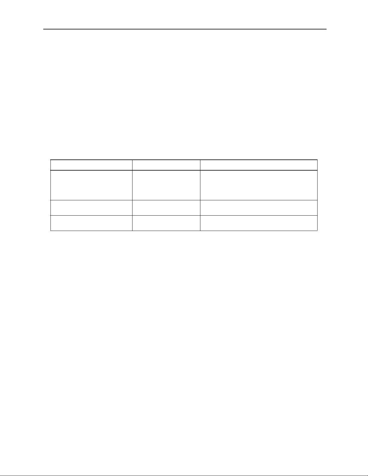
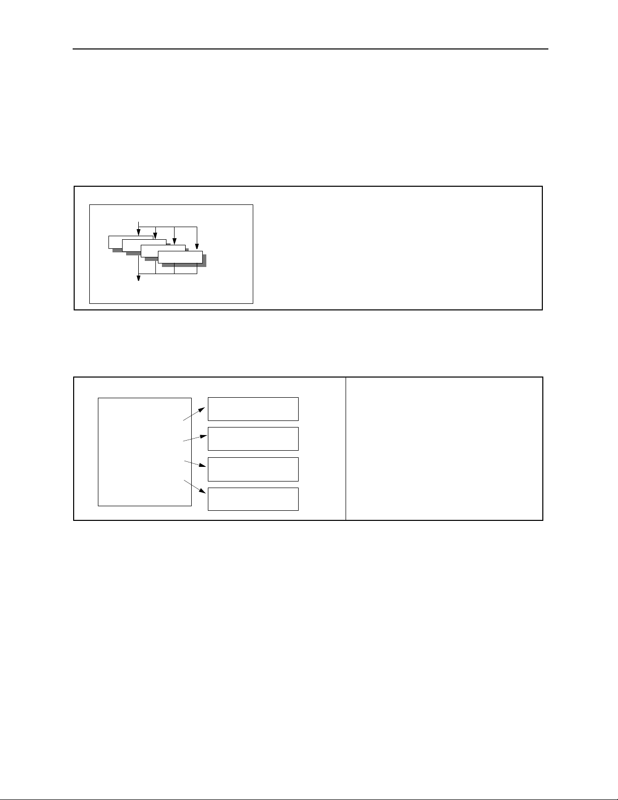
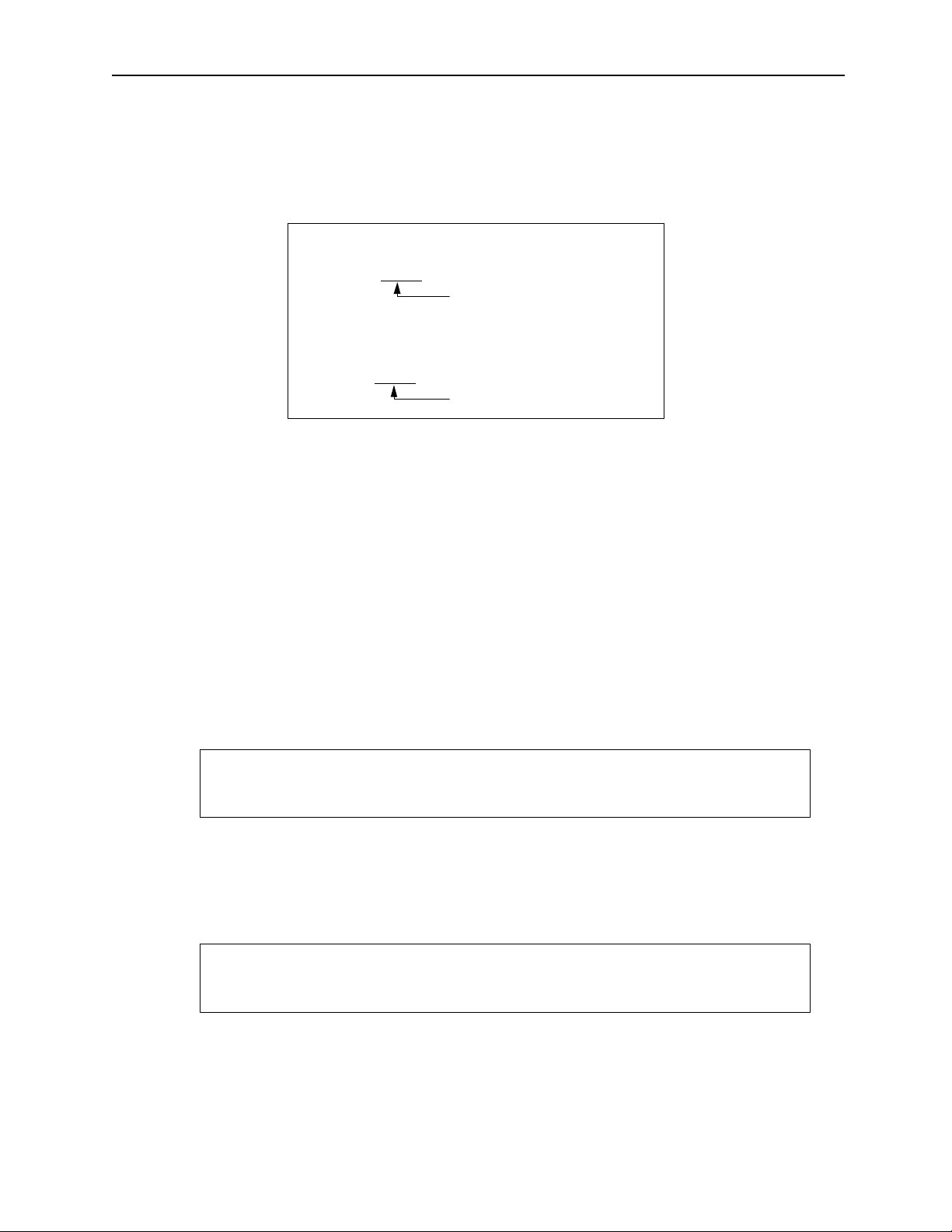
During programming of the following axi s motion commands, be sur e to che ck the move path to make
•
sure that the tool does not interfere with the work.
Commands requiring such checks:
• Positioning (MOV) commands
• Linear Interpolation (MVS) commands
• Ci r cular Interpol ation (MCC, MCW) commands
• He lical Interpolation (MCC, MCW) commands
• Time Designated Positioning (MVT) commands
• Skip (SKP) commands
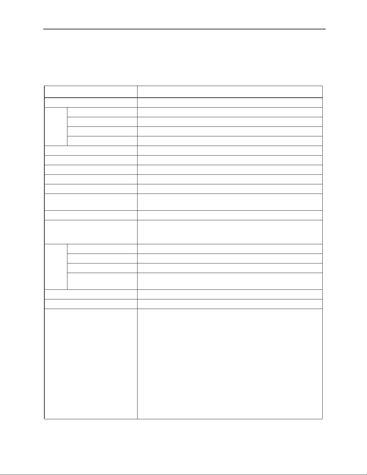
CAUTION
Example
axis2
axis3
axis2
Each axis is moving independent ly
by feed speed
axis3
Positioning motion
Current position
End position
axis1
axis1
Move Path Based on the MOV Command
Forgetti ng this check may result in tool dam age , or bodily injury.
vi
Page 8
MotionSuite ™ Series Machine Controller Programming Manual Table of Contents /P reface
!
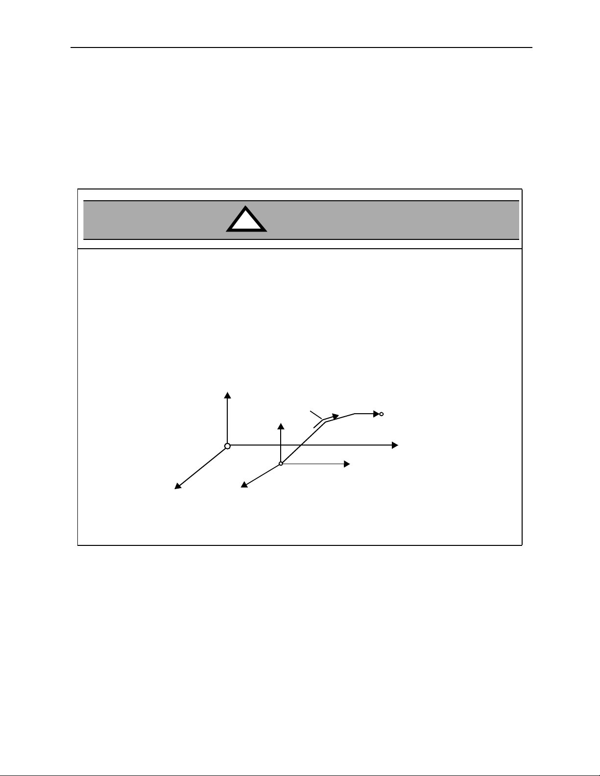
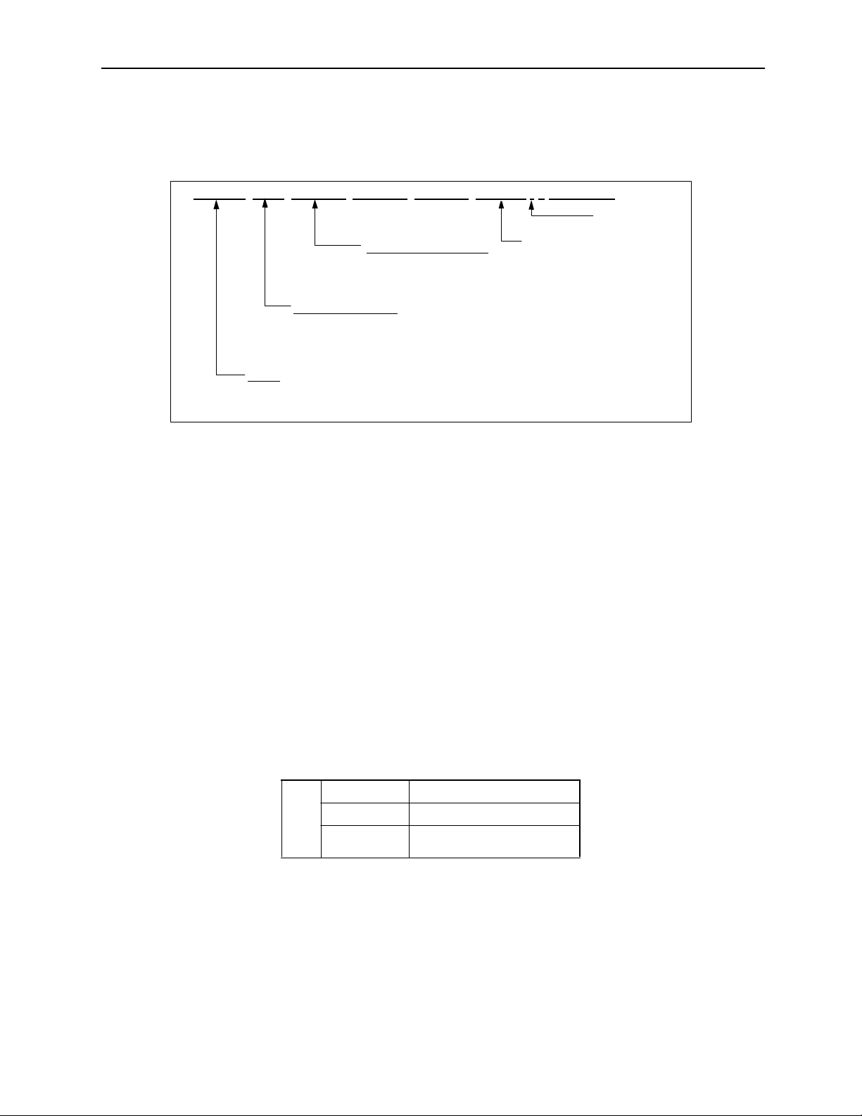
• I f the f o ll owing co m m a nd s are erroneously designat ed , the subsequ en t mo tio n o peratio n w il l b e co m pletely incorrect. V erify prior to running that these commands have been correctly designated
The following commands require such checks:
CAUTION
• Absolute mode (ABS)
• Incremental mode (INC)
• Current value change (POS)
• Machine coordinate designation (MVM)
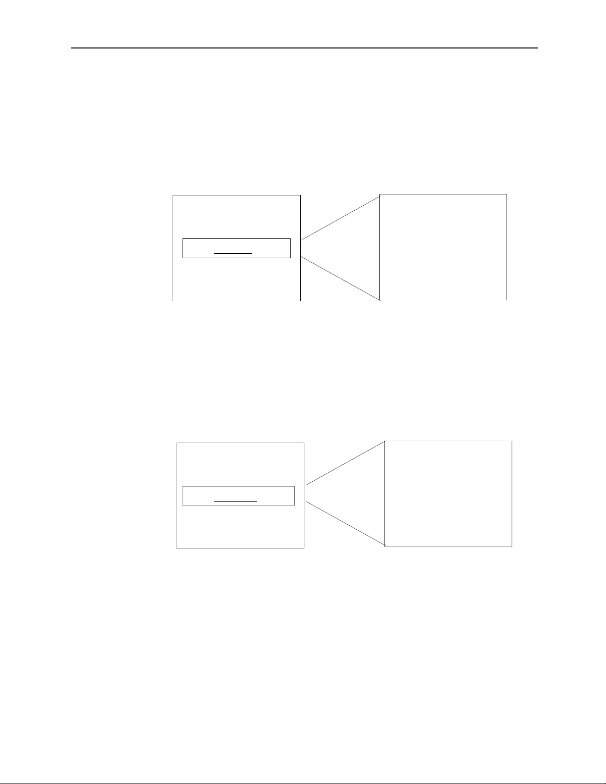
Example
axis2
axis2
(0,0)
Y
axis1
Work coordinate
Current pos ition
axis2
axis1
(0,0)
POS Command (current value change)
Forgetti ng this step may result in tool damage, or bodily injury.
vii
axis1
Page 9

MotionSuite ™ Series Machine Controller Programming Manual Table of Contents /P reface
!
! General Cautionary Items
!!
Cautions During Use
• The MotionSuite™ was n either designed nor manufactured for use in devices or systems under such critical
conditions as fol low: Transporta tion s yst ems, m edic al dev ices, aeros pace, nu cl ear powe r contro l, submari ne
relay devices, etc . Please contact Yaskaw a whe n cons idering any such special application.
• Although the MotionSui te™ is manufa cture d unde r rigorous qualit y con trol, pu t in pl ace sa fety appara tus s o
that a major accident c annot occur when apply ing the Moti onSuit e™ in an insta ll ation where the occurre nce
of major facilities damage or serious, life-threatening injury is anticipated due to the fai lure of the MotionSuite™.
• The pictures and diagrams in this manual are representative examples, and may differ from the product
received.
• These manuals may be changed as needed due to product improvements, specification change, or for
improvement in ease of use of the manual.
• These changes are made following updating of the document number of the manual, and its issua nce as a
revised edition. The publication number of the re vised edition is written on the manual cover.
• When ordering new manuals due to damage or loss, contact a Yaskawa dealer or the nearest Yaskawa corporate office li s ted on the cover, and give the document number.
• If the nameplate mounted on the product becomes illegible or damaged, order another nameplate from a
Yaskawa dealer or Yaskawa cor po r a te offic e li s t ed on th e co v e r.
• Any product modified by the custome r fall beyond Yaskawa’s product warranty . Yaskawa shoulder s no
responsibility for any injury or damage resulting from modified products.
viii
Page 10

MotionSuite ™ Series Machine Controller Programming Manual Chapter 1: Motion Programmming Outline
1 Motion Programming Ou tline
This chapter deals with the methods of creating motion programs. Motion programs are created using MotionWorks™ (Programming Unit); the programs are
executed after transfer to the MotionSuite™ series machine controller.
1.1 What is a Motion Program .................................................................................. 1-2
1.1.1 Capabilities of Motion Programs ...............................................................1-2
1.1.2 Basic P rog ram Str u ct u re ......... .................. ................... ........................ ...... 1-3
1.1.3 Function Performance List ......................................................................... 1-5
1.1.4 Motion P ro g ram Star t ............... .................. ......................... .................. .... 1-6
1.1.5 Parallel Program Operation ....................................................................... 1-7
1.1.6 Program Editor ..........................................................................................1-7
1.2 Motion Programming Method ....................................... .......... .......... .......... .......1-9
1.2.1 Input Format .............................................................................................. 1-9
1.2.2 Con trol Axes ........ .................... .............. ................... .................... ...........1-15
1.2.3 Feed Sp ee d ...... ...... .................. ......................... .................. .................. .... 1-21
1.2.4 Motion Co m m a n d Li st .............. .................. ......................... .................. .. 1-26
1-1
Page 11
MotionSuite ™ Series Machine Controller Programming Manual Chapter 1: Motion Programmming Outline
1.1 What is a Motion Program?
A general description of motion programming is presented in this chapter. Be sure to read
this section before doing any programming.
1.1.1 Capabilit ies of Motion Programs
Using MotionSuite™, it is possible to program the specific motions necessary for
industrial machines. The main characteristics of motion progr ams are provi ded below
for reference:
Motion Program MPM001
PFORK S1, S2, S3, S4
S1
S2
S3
S4
S5: PJOINT
Ladder Program
MSEE MP M001 DA0000
MSEE MP M002 DA0002
MSEE MP M003 DA0004
MSEE MP M004 DA0006
Motion Program
Motion Pro gram
Motion Pro gram
Motion Pro gram
Motion Pro gram
MPM001
MPM002
MPM003
MPM004
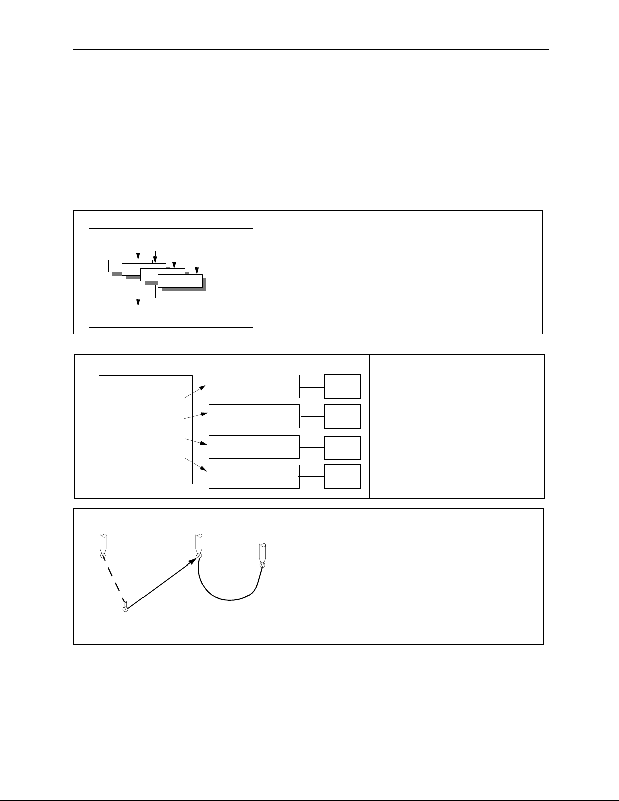
Parallel Operation 1
• A maxi mum of fou r pro grams c an be operat ed in par allel
using the PFORK command within a si ngle motion program.
• Axes may be freely combined in up to four groups.
Machine
Simultaneous Control of
Multiple Machines
MC-1
MC-2
• Several prog rams can be op e r at ed in
parallel.
• A maximum of 14 axes can be controlled.
MC-3
MC-4
Maximum 14
axes simultaneo u s
positioning
Maximum 14
axes simultaneo u s
linear interpolation
2 axes
simultaneous
circular interpolation
Enhanced Motion Commands
• Positionin g 14 axes maximum
• Linear Interpolation 14 axes maximum
• Circular Interpolation 2 axes
• Helical Interpolation 3 axes
1-2
Page 12

MotionSuite ™ Series Machine Controller Programming Manual Chapter 1: Motion Programmming Outline
Example of Operation Com ma nds:
MW81D=AB01H*SIN(100)+50;
MW5=BCD (1W0001);
IF CF476 <> DF897;
IF MW0001 > 7;
IF 0B0 == 1;
0B0 = (IB0 | IB2 | IB3) & 1B1;
MW6 = SQT (MW809);
Conditional Branching Commands
IF <Conditional>
•
• Processed when conditions established
•
•
ELSE
•
• Processed when conditions not established
•
•
IEND
Repeat Commands
WHILE <Conditional>
•
• Processing
•
•
WEND
Calculations are Flexible and Dependable
• Integer arithmetic operations
• Real number arithmetic opera tions
• Logical operations
• Trigonometric operations
• Exponents
• Logarithms
•etc.
Control Commands
• Conditional branching comm ands (IF /ELSE)
• Repeat commands (WHILE)
• Timer commands (TIM )
• Subroutines (MSEE)
• Parallel execution com mands (PFORK)
• Selection execution commands (SFORK)
1.1.2 Basic Program Structure
a. Motion programs are written in a text format motion language. Up to 256 of
these motion programs can be created separately.
b. Motion programs are of the following two types: Main programs (MPM
which can be called out from DWG.H, and sub-programs (MPS
can be called out from the main program.
Important Point
Numbers of the MPM and MPS programs cannot be duplicated.
1-3
"""
"""
) which
)
Page 13
MotionSuite ™ Series Machine Controller Programming Manual Chapter 1: Motion Programmming Outline
Motion Program Types
Classification
Designation
Method
Main Program MPM"""
1~256
Sub-Program MPS"""
1~256
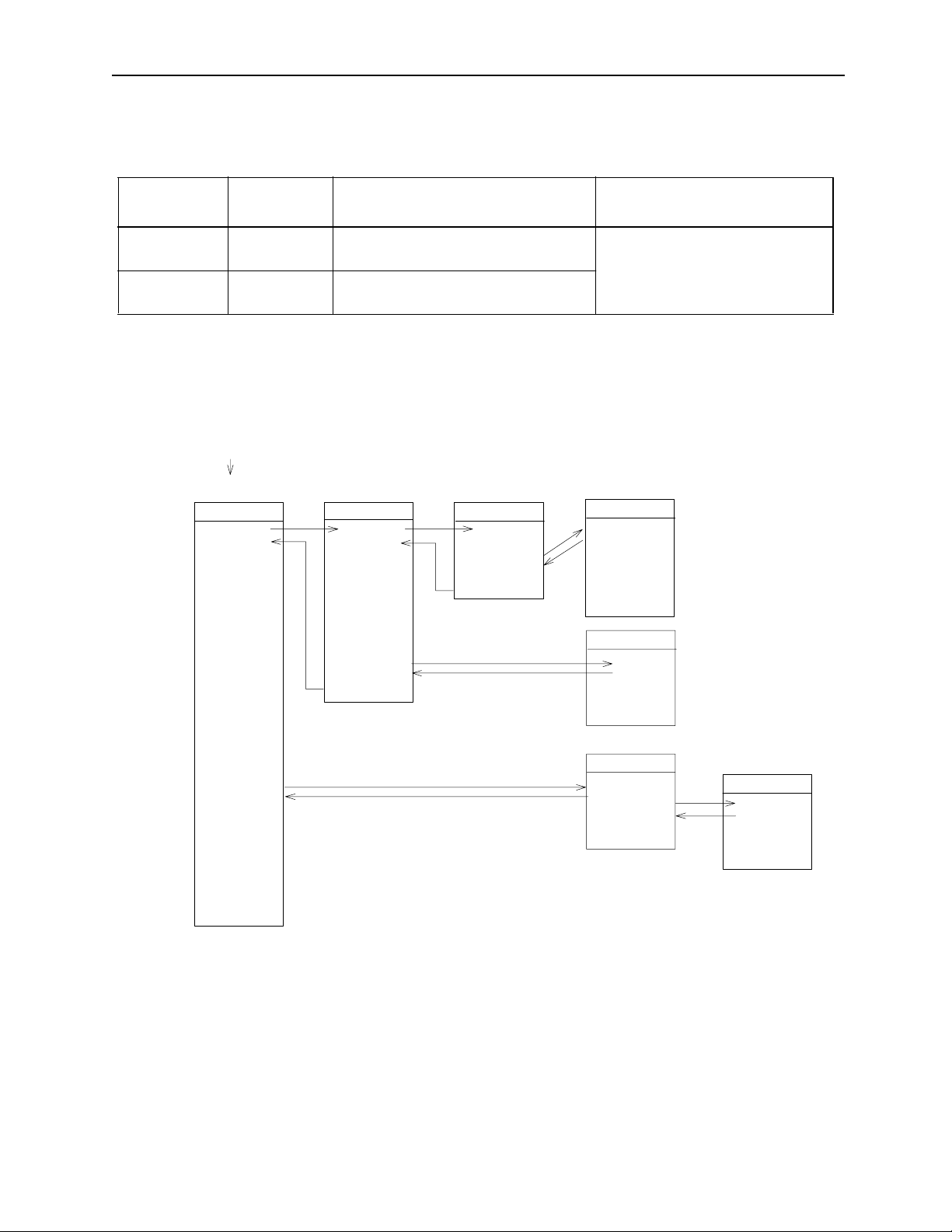
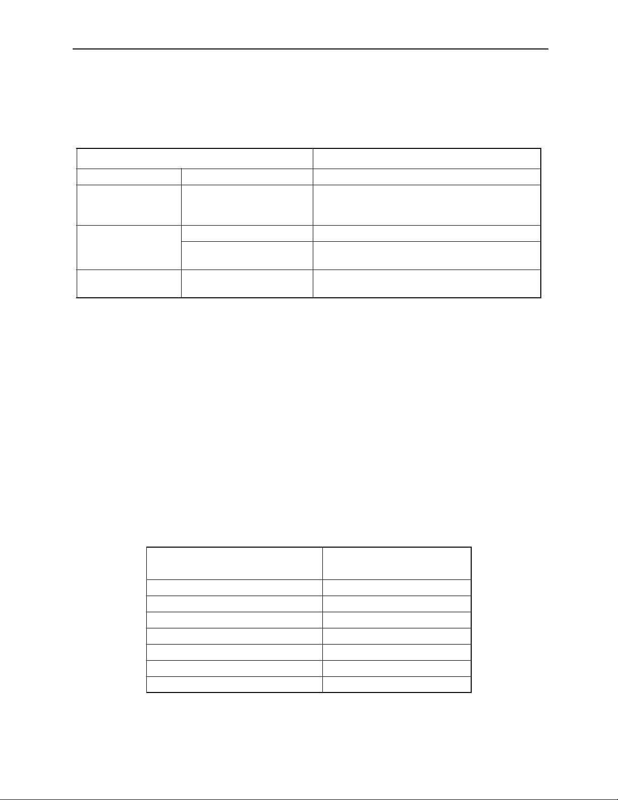
c. Motion Program Execution Processing Format
Always refer to the motion program from the H drawing by using the MSEE
command. H drawings can be referenced from source drawings, sub-drawings,
or sub-sub-drawings.
System program starts by
operating conditions
Source Drawing
DWG.H
SEE H.01
Characteristics
Number of Programs
Can be called out from an H drawing A maximum of 256 combined
main programs and sub-programs
Can be called out from a main program
Sub-drawing
DWG.H01
SEE H01.01
Sub-sub-drawing
DWG.H01.01
MSEE MPM001
DEND
can be created.
Motion Program
MPM001
VEL [a1]5000 [b 1]..
FMX T100000000;
IAC T25;
IDC T30;
MOV [a1]300. [b1]..
MVS [a1 ]20 0. [b1]..
•
•
END
MPM002
MSEE MP M0 0 2
DEND
END
MPM003
MSEE MPM003
MSEE MPS001
END
DEND
Subroutine
MPS001
RET
Figure 1.1: Motion Program Execution Processing Format
Supplement
See Section 3.4 “User Programs” in the MP930 Machine Controller Hardware Manual for details regarding this figure.
1-4
Page 14
MotionSuite ™ Series Machine Controller Programming Manual Chapter 1: Motion Programmming Outline
1.1.3 Function Performance List
The MP9xx motion program function specifications are as follows:
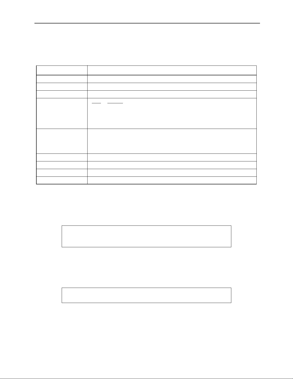
MP9xx Motion Control Function Specifications
Item Specifications
Number of Control Axes 1~14 maximum
Position Control Linear, rotational, unlimited, independent axis
Interpolation Linear: 14 axes, Circular: 2 axes, Helical: 3 axes
Speed Control None
Specs
Control
Torque Limit Limited (torque limit set by parameters only)
Command Unit mm, inch, deg, pulse
Minimum Command Setti ng Unit 1, 0.1, 0.01, 0.001, 0.0001, 0.00001
Maximum Command Value -2147483648~+2147483647 (with 32-bit symbols)
Speed Command Unit mm/min, inch/min, deg/mi n, pulse/min
Accel/Decel Type Linear, S-curve, separate accel/decel
Override Functions Positioning: 0.01~100.00% of axis uni t
Interpolation: 0.01~100.00% of group unit
Coordinates Cartesian Coordinates
Zero-Point Return 4 Types:
Torque+C-phase, zero-point LS, torque+zero-point LS, C-phase
There is a zero-point setting function
Language Dedicated motion language
Number of Tasks A maximum of four programs can be simultaneously execut ed in parallel.
Number of Programs 256 maximum
Programs
Program Volume 80 Kbytes (characters)
(Adjustable by the volume of ladder progra m used: 100 Kbyte maximum)
Applied Servo Amplifier SGD-"""N/SGDB-""AN
Encoder Incremental/Absolute
Command Language Axis Motion Commands : 8 types
MOV, MVS, MCW , MCC, ZRN, SKP, MVT, EXM
Basic Control Commands : 5 types
ABS, INC, POS, PLN, MVM
Speed/ Accel/D ecel Commands : 7 types
ACC, SCC, VEL, I A C, IDC, IFP, FMX
Advanced Control Commands : 4 types
PFN, INP, SNG, UFC
Control Commands : 9 types
MSEE, TIM, IOW, END, RET, IF ELSE IEND, WHILE WEND,
PFORK JOINTO PJOINT, SFORK JOINTO SJOINT
Operation/Sequence Control Commands : 36 types
=, +, -, *, /, MOD, |, ^, &, !, (), S{}, R{}, SIN, COS, TAN, ASN, ACS,
ATN, SQRT, BIN, BCD, ==, <>, >, <, >=, <=, TON, TOF, SFR, SFL,
PON, NON, BLK, CLR
1-5
Page 15
MotionSuite ™ Series Machine Controller Programming Manual Chapter 1: Motion Programmming Outline
1.1.4 Motion Program Start
The motion program is started from an “H” drawing ladder program. Start is initiated
by motion program start commands (MSEE) from within the ladder program and a
low to high transition of the program run start request bit. Motion programs are designated directly by the program number and indirectly by the register number containing
the program number.
ABS;
MOV X_Y_
MVS X_Y_F
MSEE MPM001 DA0000
IOW MB0001
MOV X_Y_
•
•
Ladder Program
Motion Control Program
Figure 1.2: Motion Program Start by Direct Designation
ABS;
•
MOV X_Y_
MVS X_Y_F
MSEE MW00200 DA0000
MPM Number is in MW00200
Ladder Program Motion Contro l Pr ogram
IOW MB0001
MOV X_Y_
•
Figure 1.3: Motion Program Start by Indirect Designation
1-6
Page 16
MotionSuite ™ Series Machine Controller Programming Manual Chapter 1: Motion Programmming Outline
1.1.5 Parallel Program Operation
With MP9xx, it is possible to program freely with various machine activities, due to
capabilities for parallel running that make complex motion control possible. Parallel
running of motion programs is available in the two following forms.
a. With motion program PFORK commands, parallel running of a maximum of 4
programs within 1 program is possible.
Motion Program MPM001
PFORK S1, S2, S3, S4
S1
S2
S3
S4
S5: PJ O INT
b. With ladder program MSEE commands, parallel running of multiple motion pro-
grams is possible. (When automatically generated with MotionWorks™ group
setting display , parallel running of a maximum of 4 programs is possible.)
Ladder Program
Motion Program
MSEE MPM 00 1 DA 00 00
MSEE MPM 00 2 DA 00 02
MSEE MPM 00 3 DA 00 04
MSEE MPM 00 4 DA 00 06
Motion Program
Motion Program
Motion Program
MPM001
MPM002
MPM003
MPM004
Parallel Operation 1
• A maximum of four (4) programs can be operated i n parallel us ing the PFORK command within a single motion
program. The PFORK command must be ended with the
PJOINT command.
Parallel Operation 2
• Several programs can be operated in parallel
by using the ladder program MSEE command.
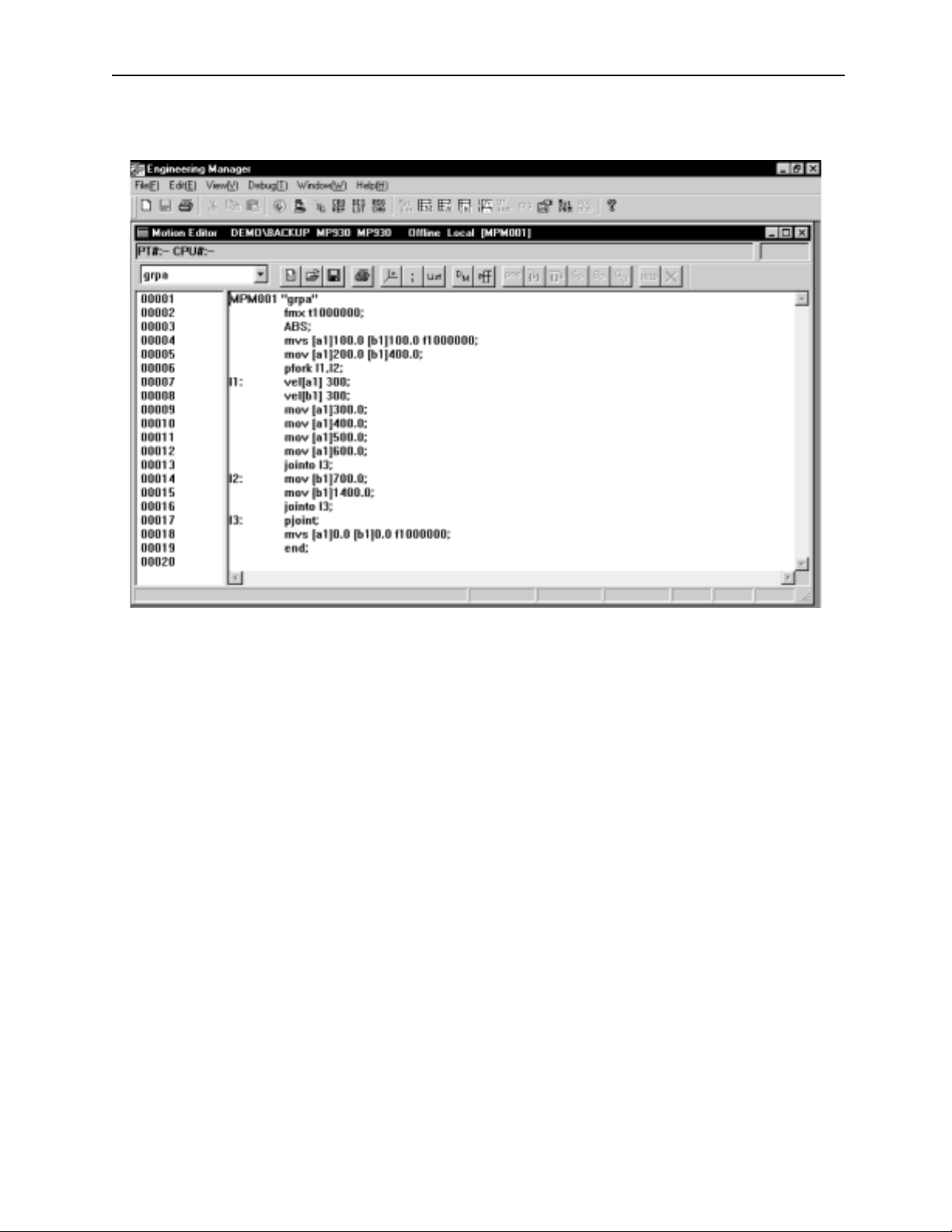
1.1.6 Program Editor
The motion program editor is generated on the MotionWorks™ (programming device)
motion program editor display. The editing display contains the following functions.
a. The same functions as the text editor, such as cut & paste, look-up, replace, and
jump
b. Special functions such as debugging operations and program instruction moni-
toring
c. Function for importing and reading text editor files
1-7
Page 17
MotionSuite ™ Series Machine Controller Programming Manual Chapter 1: Motion Programmming Outline
d. Function for writing and exporting motion program files as text files.
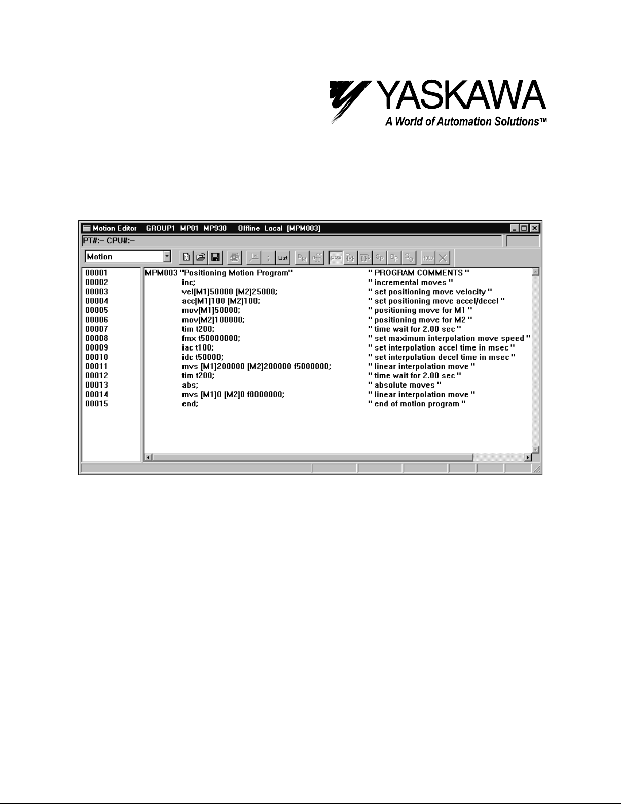
Figure 1.4: MotionWorks™ Motion Program Editor Display
Supplement
For motion program editor function details, please refer to the MotionSuite™ Series
Machine Controller Software Manual.
1-8
Page 18

MotionSuite ™ Series Machine Controller Programming Manual Chapter 1: Motion Programmming Outline
1.2 Motion Programming Method
This section deals with the basic rules for creating motion programs. Read this section
thoroughly prior to program execution.
1.2.1 Input Format
! Motion Program Sample
Motion programs are created in variable-length block format.
Program Sample
Block Number Program
00001 MPM001"sample” ...Program number and comment
00002 FMX=T1000000; ...Interpol ation feed high-speed setting
00003 IAC=T100; ...Interpolation feed accelerat ion time setting
00004 IDC=T100; ...Interpolation feed deceleration time setting
00005 VEL [X1]10000 [Y1]2000 [Z1]3000; ...Feed speed sett ing
00006 INC; ...Increment al mode command
00007 MOV [X1]100.[Y1]150.[Z1]200 .; ...Fas t feed
00008 MVS [X1]100.[Y1]50.F500000; ...Linear interpolation
00009 IOW IW0011=1; ...
00010 MW0100=(MW0110*100+50)/100; ...
00011 MW0200=(MW0210*100+50)/100; ...
00012 ABS; ...
00013 MOV [X1]MW0100 [Y1]MW0200; ...
00014 POS [X1]0 [Y1]0 ...
00015 PFORK LA01, LA02, LA03, LA04 ...Parallel operation command
00016 LA01: INC; ...Label
00017 MOV [X1]1000.; ...
00018 JOINTO LA05; ...
00019 LA02: INC; ...
00020 MOV [X1]2000.; ...
00021 JOINTO LA05; ...
00022 LA03: ABS; ...
00023 MV S[Z1]1500 F50000; ...
00024 MW1000=12345; ...
00025 JOINTO LA05; ...
00026 LA04: MW1100=1000; ...
00027 IOW IB101==1; ...
00028 JOINTO LA05; ...
00029 LA05:PJOINT ...Closes paral lel operation command
00030 END; ...Closes program
1-9
Page 19
MotionSuite ™ Series Machine Controller Programming Manual Chapter 1: Motion Programmming Outline
! Input Format
The variable length input formats are as given in the following table:
Variable Input Format List
Item Input Format
Program Number MPM
Label 8 char acters maximum
Motion Commands 3 alphabetical characters (some commands are other than 3 letters)
Coordinate
Language
Interpolation Fee d
Speed
Wait Time TIM T1000 10 msec units (no fractions)
Sub-program Number MPS
P Designation P100; Interpolation feed spee d ratio setting 1~100
Close Block ;
""" """
[abcd
] ± 123,456
AB C
A: Axis Name
B: Pos/Neg design ation possible
C: See Item 1.2.2 “Control Axes” for details on coordinates
F3000000
Changes accordin g to the number of places below the decim al point. (set paramete r)
3000.000mm/min when numb er of places below decimal poi nt =3
30.00000mm/min when numb er of places below decimal poi nt =5
""" """
= 1~256
= 1~256
! Leading Zero
Numbers following the characters, including program numbers and register (variable)
numbers, can omit the leading zero.
Example
[X1]00123
[X1]MW00010
MPS002
! +/- Symbol
Although the plus sign may be omitted from numbers, the negative sign may not be
omitted.
Example
[X1]00123
[X1]-123
Supplement
Decimal places cannot be used in the interpolation feed speed (Fxxxx) command.
F30000.000 is not possible; enter it as F30000000.
⇒
[X1]123
⇒
[X1]MW100
⇒
MPS2
⇒
[X1]123
⇒
[X1]-123
1-10
Page 20

MotionSuite ™ Series Machine Controller Programming Manual Chapter 1: Motion Programmming Outline
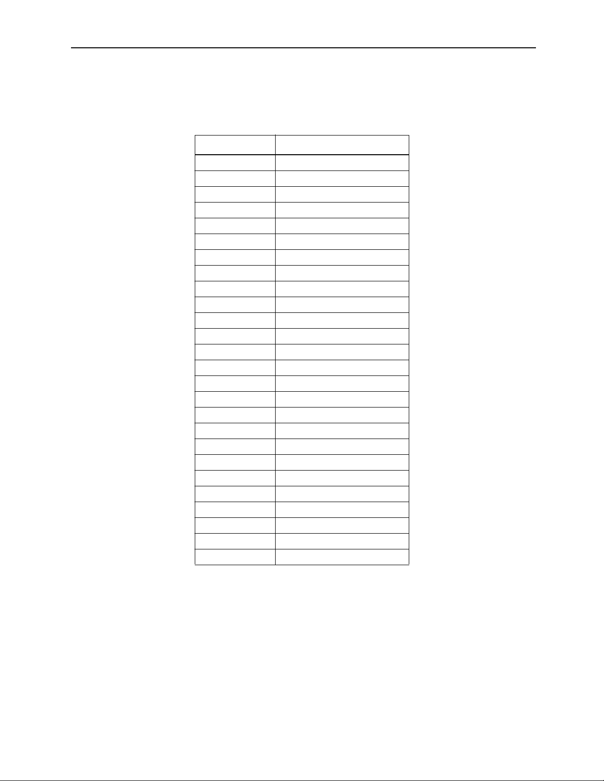
! Usable Characters
The usable characters and their meanings are given in the following table.
Usable Character List
Character Meaning
CC register
DD register
II register
MM register
OO register
SS register
F Interpolation feed speed
P Interpolation feed speed override
R Circular radius
SS Step signal number
T Timer value, number of circle turns, FMX, IAC, IDC
U Cir cular midpoint coordinate 1 (horizontal)
V Cir cular midpoint coordinate 2 (vertical)
MPS Sub-program number
1-11
Page 21
MotionSuite ™ Series Machine Controller Programming Manual Chapter 1: Motion Programmming Outline
! Function Characters
The function characters and their meanings are given in the following table.
Function Character List
Character Meaning
SP Space
TAB Tab
; End of block
ENTER
0~9 numbers
A~Z Alphabet
. Decimal point
+ Operation
- Operation
* Operation
/ Operation
| Operation
^ Operation
& Operation
! Operation
= Operation
() Operation
== Operation
> Operation
< Operation
<> Operation
>= Operation
<= Operation
S {} Operation
R {} Operation
——
Changes row
1-12
Page 22
MotionSuite ™ Series Machine Controller Programming Manual Chapter 1: Motion Programmming Outline
! Program Number Hand ling
The program number is a number for the purpose of program discrimination. There
are two kinds of programs: Main programs and sub-programs. The numbers 1~256
may be applied to each.
!
Main Programs
"""
MPM
Program number (1~256)
!
Sub-programs
"""
MPS
Program number (1~256)
Figure 1.5: Motion Program File Names
Supplemental It em
(1) The same number cannot be designated for both main programs and sub-programs.
(2) Up to 256 programs of the Main program and Subprogram combined can be
created.
! Comment Writing
It is possible to write comments within the program. These comments are saved
within the controller. There are two ways to create a comment, as follows:
1. Surrounding a comment statement with quotation marks.
“Character string”
Example
ZRN [AXIS1]0 [AXIS2]0 [AXIS3]0; “Zero return all axes”
MVS [AXIS1]100.0 [AXIS2]200.0 [AXIS3]3 00.0; “Three axis linear int erpolation”
2. All characters following the first quotation mark in a line become comments
without surrounding the line in quotation marks if
“Character string
Example
“Move to the wait machine position by linear interpolation after all axi s zero point return
ZRN [AXIS1]0 [AXIS2]0 [AXIS3]0;
MVS [AXIS1]100.0 [AXIS2]200.0 [AXIS3]3 00.0;
ENTER
ENTER
is pressed.
1-13
Page 23
MotionSuite ™ Series Machine Controller Programming Manual Chapter 1: Motion Programmming Outline
! Creation of One-Block Commands
a. A one-block command is made according to the input format list. A representa-
tive example of a single block is shown below.
LABEL: MVS [X1] 20.0 [Y1] 30.0 [Z1] 40.0 F300000 ; “ Comment”
End of block
Coordinate Language
Axis coordinate value and amount
of axial incremen tal moti o n
Motion Command
Designates motion operation type and control type.
Label
Label to be bran ched t o when us i ng paral lel
execution or selected execution commands
Interpolation fe ed s pee d
.
b. Always be sure to insert a space [SP] between the motion command and the
coordinate language.
c. Although there is no restriction on the number of characters in a single line of a
single block, we recommend that the number of characters be kept to within a
range that can be displayed on-screen for the sake of program viewability.
d. A [;] is needed any time that a block is completed.
e. The label is used as the target block for the parallel execution command
(PFORK) or selection execution command (SFORK).
! Label
A label must be us ed for the parallel execution command (PFORK) or selection execution command (SFORK). Attach a colon [:] to the end of a 1~8 character string of
alphanumeric characters or symbols. The characters that can be used in a label are
shown below. The first character in a label must be alphabetical.
Numbers 0~9
Letters A~Z, a~z
Symbols $, %, ¥, @,—, _, .
Characters
1-14
Page 24

MotionSuite ™ Series Machine Controller Programming Manual Chapter 1: Motion Programmming Outline
Example
PFORK LAB1, LAB2
LAB1: ZRN [AXIS1]0 [AXIS2]0 [AXIS3]0;
JOINTO LAB3
LAB2: MVS [AXIS1]100.0 [AXIS2]200.0 [AXIS3]300.0;
JOINTO LAB3
LAB3: PJOINT
Important Point
1. The error “Duplicate Label Defined” results if the same label is used multiple
times within a program.
2. An error results in the number of PFORK branches if the number of labels differs.
1.2.2 Control Axes
Axis Names
!
It is possible to set a desired axis name of up to eight characters. The axis names are
set in the Group Definitions Screen in MotionWorks ™. The characters that can be
used in a name, as well as the default axis names, are given below.
Usable Characters 0~9, A~Z, a~z
Axis Name Examples [AXIS1] [X1] [CONV1]
Default Axis Names If fou r axes are designated: [A1] [B1] [C1] [D1]
If eight axes are designat ed:
[A1] [B1] [C1] [D1] [E1] [F1] [G1] [H1]
Supplement
1. Always be sure to enclose axis names written in 1 ~ 8 alphanumeric characters
within [ ].
2. The same axis name cannot be set into multiple axes.
3. An error results if an axis name is designated in the motion program different
from the axis name set in the Group Definition Screen.
1-15
Page 25
MotionSuite ™ Series Machine Controller Programming Manual Chapter 1: Motion Programmming Outline
! Coordinate Language List
The motion amount and coordinate values attached to the axis name are called “coordinate language” in this book. The meanings of the coordinate language used in this
system are shown in the table below.
Coordinate La nguage Designatio n Method Meaning
Axis Name [X1], [Y1], [AXIS] Designates axis to be moved
Motion Amount or
Coordinate Value
Auxiliary Data for Circular Interpolati on and
Helical Interpola tion
Amount of External
Positioning Motion
Important Points
Direct Designation: 123.456
Variable Designation:
MW0100
R Circula r interpolation radius (set by the increm ent)
U
V
D Distance of motion after external signal input (set by
Coordinate value of designated axis , or inc rem ental
motion range
Circular interpolation center coordinate (Horizontal)
Circular interpolation center coordinate (Vertical)
the incr em e nt)
1. The 32-bit integer data type is used when the motion amount or coor dinate value
is designated by a variable.
(Ex.) ML0100
2. When there are fractions, insert zeroes for the number of places following the
decimal point.
(Ex.) Use 300000 to designate 300.000 when the number of decimal places = 3.
However, the servo parameter area (IWCxxx, OWCxxx) in the I, O registers
cannot be used for variables of the motion amount or coordinate value.
! Number of Simul taneously Controlled Axes
The number of simultaneously controlled axes designated from the motion program is
shown in the following chart.
Number of Simultaneously Controlled Axes List
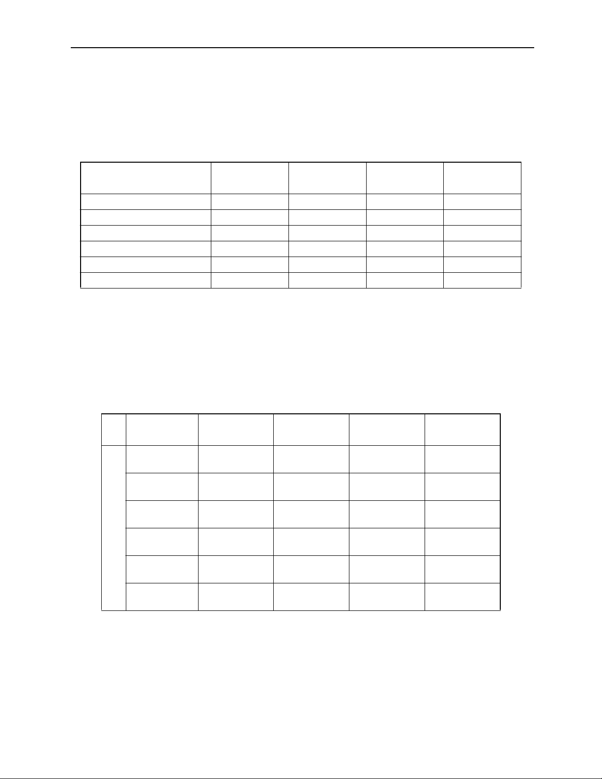
Command Language
Positioning (MOV) 14 axes maximum
Linear Interpol ation (MVS) 14 axes maximum
Circular Interpolation (MCW/MCC) 2 axes
Helical Interpolation (MCW/MCC) 3 axes
Skip Command (SKP) 14 axes maximum
External Positioning (EXM) 1 axis
Time Designated Positioning (MVT) 14 axes maximum
Number of Simultaneously
Controlled Axes
1-16
Page 26
MotionSuite ™ Series Machine Controller Programming Manual Chapter 1: Motion Programmming Outline
! Command Units
The programmable command units are in accordance with the settings of b0~b3
“Command Unit Selection” of set-up parameter 17 “Servo Module Function Selection
Flag” and set-up parameter 18 “Number of Places Below Decimal Point.”
Command Unit List
Parameter Setting
# of Places Below Decimal=0 1 pulse 1mm 1º 1”
# of Places Below Decimal=1 1 pulse 0.1mm 0.1º 0.1”
# of Places Below Decimal=2 1 pulse 0.01mm 0.01º 0.01”
# of Places Below Decimal=3 1 pulse 0.001mm 0.001º 0.001”
# of Places Below Decimal=4 1 pulse 0.0001mm 0.0001º 0.0001”
# of Places Below Decimal=5 1 pulse 0.00001mm 0.00001º 0.00001”
Command Unit
Pulse
Command Unit mmCommand Unit
deg
Command Unit
inch
Supplement
The number of places below the decimal point are disabled if command unit = pulse.
The decimal points in the motion pr ogram input and posit ion monitor dis play are also
meaningless.
! Maximum Command V alue
The maximum values of single motion commands are given in the table below.
# of Decimal
Places
0 -2147483648
1 -2147483648
2 -2147483648
3 -2147483648
Limited Lengths
4 -2147483648
5 -2147483648
Command Un it
Pulse
~2147483647
~2147483647
~2147483647
~2147483647
~2147483647
~2147483647
Command Unit mmCommand Unit
deg
-2147483648
~2147483647
-2147483648
~214748364.70~3599999.9
-2147483648
~21474836.470~359999.99
-2147483648
~2147483.6470~35999.999
-2147483648
~214748.36470~3599.9999
-2147483648
~21474.836470~359.99999
0~
35999999
Command Unit
inch
-2147483648
~2147483647
-2147483648
~214748364.7
-2147483648
~21474836.47
-2147483648
~2147483.647
-2147483648
~214748.3647
-2147483648
~21474.83647
1-17
Page 27
MotionSuite ™ Series Machine Controller Programming Manual Chapter 1: Motion Programmming Outline
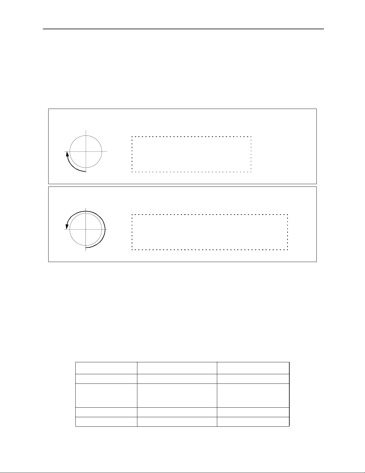
! Designation of “Absolute Mode” in a Rotary Axis
When an absolute value command (designation mode in a range of 0~359.999º) is
used in a rotary axis, the commanded +/- sign shows the rotation direction, and the
command value signifies the absolute position.
Example
When designating a position 180º from the current position:
Example of Designating the Rotary Axis Absolute Mode
0º
270º
Example of Designating the Rotary Axis Absolute Mode
270º
180º
0º
180º
90º
90º
ZRN [X1]0;
INC MOV [X1]180.0;
ABS MOV [X1]270.0; moves 90º clockwise
ZRN [X1]0;
INC MOV [X1]180.0;
ABS MOV [X1]-270.0; moves 270º counte r-clockwise
Supplement
When moving to the 0º position by designating the absolute mode in a rotary axis, -0.0
cannot be designated in a counter-clockwise motion. In this case, designate -360.0.
! Number and Variable Tabulation Method
Numbers used in motion programs are of two types: parameters and variables. The
setting method for these numbers is given below.
a. Parameters
Tabulation of Numbers that Can be Designated
Type Range Notation Example
Decimal Integers -2147483648~2147483647 0, 734, +823, -2493
Decimal Fractions -2147483.648~2147483.647
Changes accord ing to number
of decimal place s
Hexadecimal Integers 0~FFFFFFFFH FFFABCDEH, 2345H, FH
Real Numbers
1-18
763., +824.2, -234.56
-321.12345
Page 28
MotionSuite ™ Series Machine Controller Programming Manual Chapter 1: Motion Programmming Outline
b. Variables
The following types of variables exist for use in motion programs. Use them
according to the application.
Types of Variables and Tabu lation Method
Type
Global
Variables
Local Variables D Register DB DW DL DF
Variable
Type
S Register SB SW SL SF
M Register MB MW ML MF
I Register IB IW IL IF
O Register OB OW OL OF
C Register CB CW CL CF
BIT WORD LONG FLOAT
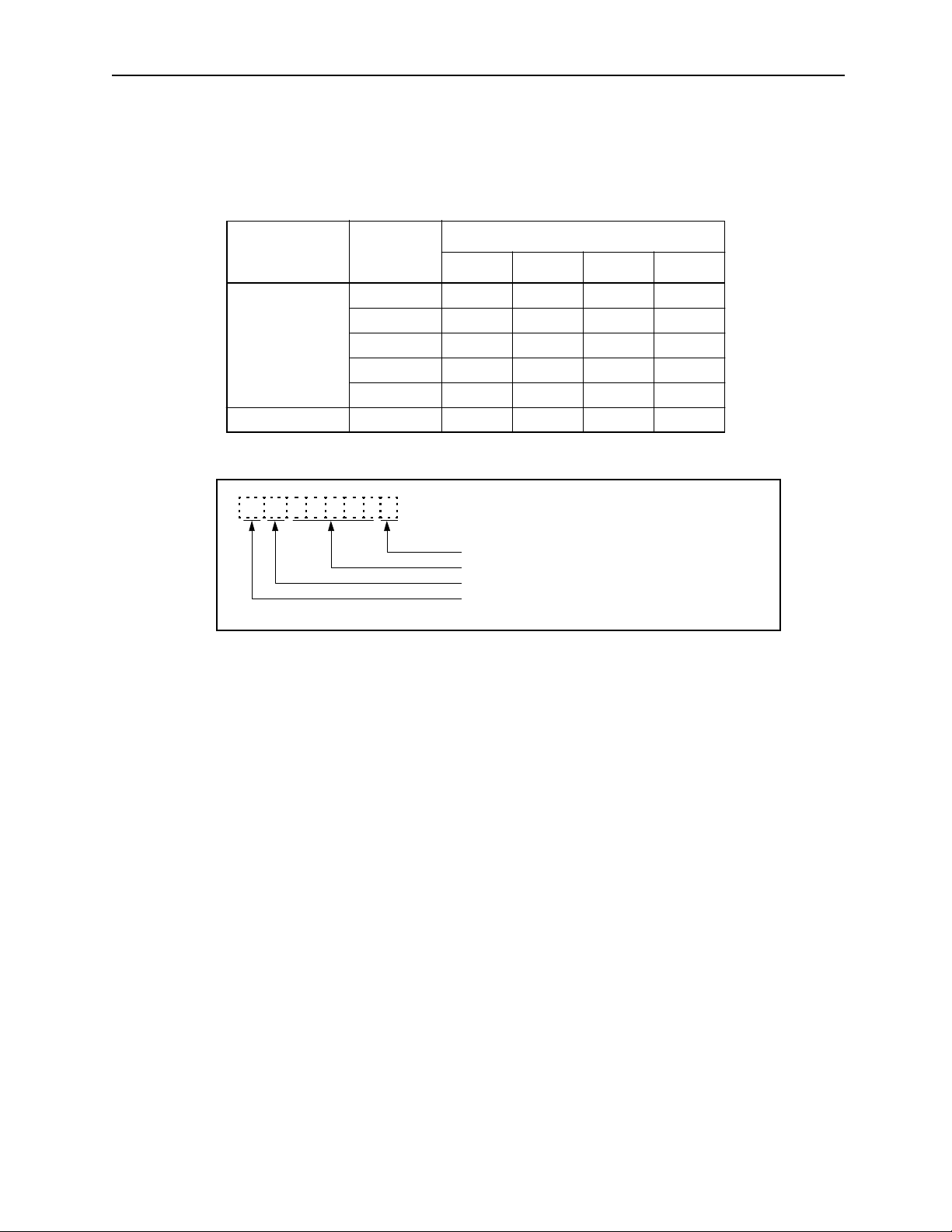
Data Type
M B 1 2 3 4 5 F
Bit Position: Enabled only with bit data
Variable Address: B, W, L, F
Data Type: B, W, L, F
Variable Name: S, M, I, O, C, D
(Ex.) MB001001=1;
MW00100=1234;
ML00100=12345678;
MF00100=1234.5678;
1-19
Page 29

MotionSuite ™ Series Machine Controller Programming Manual Chapter 1: Motion Programmming Outline
! Calculations and Functions
Calculations can combine global variables, local variables and constants with
operators and functions. The result can be substituted by a variable. Calculation and
functions use the following commands.
Type Command Name Command Format
= Substitution MW– =MW–;
+ Addition MW– =MW– +MW–;
Value Calculations
Logical Calculations
Value Comparisons
Data Operations
Basic Functions
– Subtraction MW– =MW – –MW
* Multiplication MW– =MW–*MW–;
/ Division MW– =MW–/MW–;
MOD Remainder MW– =MOD;
| OR (Logical OR) MB– =MB– | MB–;
^ XOR (Exclusive OR) MB– =MB– ^MB–
& AND (Lo gical AND) MB– =MB– &MB–;
! NOT (Invert) MB– =MB– !MB–;
= = Same IF MW– = =MW–;
< > Not same IF MW– < >MW–;
> Greater IF MW– >MW–;
<Less IF MW– <MW–;
>= Greater or equal IF MW– > =MW–;
<= Less or equal IF MW– < =MW–;
SFR Right-shift SFR MB– N– W–;
SFL Left-shift SFL MB– N– W–;
BLK B lock tra nsfer BLK M W– MW– W–;
CLR Clear CLR MB– W–;
SIN Sine SIN (MW–);
COS Cosin e COS (M W–);
TAN Tangent TAN (MF–);
ASN ARC sine ASN (MF–);
ACS AR C cosine ACS (MF–);
ATN A R C tang e nt ATN (MW– );
SQT Square root SQT (MW–);
BIN BCD→BIN BIN (MW–);
BCD BIN→BCD BCD (MW–);
S{} Designated bit ON S{MB–}=MB– &MB–;
R{} Designated bit OFF R{MB–}=MB– &MB–;
1-20
Page 30

MotionSuite ™ Series Machine Controller Programming Manual Chapter 1: Motion Programmming Outline
1.2.3 Feed Speed
! Fast Feed Speed
a. Fast feed speed is used in the following axis motions:
• Positioning (MOV) commands
• JOG run (JOG) operation
• Step run (STEP) operation
b. Set the fast feed speed in the setup parameters “Fast Feed Speed (OLxx22) or in
the motion program “Feed Speed Change Command (VEL)”.
• Fast Feed Speed Parameters (set in setup parameters)
Parameter Number Name Setting Range Unit
OLxx22 Fast Feed Speed
• Methods for setting Fast Feed Speed in the motion program
1. Direct Setting Method for Fast Feed Speed Parameters
OLC022=6000 ; Sets fast feed speed for the first axis
OLC062=5000 ; Sets fast feed s pee d for the second axis
OLC0A2=7000 ; Sets fast feed speed for the third axis
2. Setting Method Using t he F eed Speed Change Command (VEL)
VEL [X1] 6000 [Y2] 5000 [Z1] 7000
0~2
31
-1
By command unit
c. The fast feed can be switched to override within a range of 0~327.67%. This can
be set for each axis using the setup parameter “Override (OWxx2C).” There are
three override setting methods: in the motion program, in the ladder program,
and in the setup parameter.
Command Speed × Override = Output Speed
(OLxx22) (OWxx2C)
Command Speed
(OLxx22)
Override Function
Selection
Fixed Parameter 17
Bit 9
Enable
Disable
Override
(OWxx2C)
100%
Supplement
1. Override is normally enabled during run. Ladder programs and motion programs can be modified by parameter setting during axis motion.
2. When the output speed from the override setting data is outside of operable
range, the Parameter Setting Error results.
Output
Speed
1-21
Page 31

MotionSuite ™ Series Machine Controller Programming Manual Chapter 1: Motion Programmming Outline
! Interpolation Feed Speed
a. The feed speed for the interpolation feed command is set by the number follow-
ing Character (F). It is sometimes referred to as the F command.
b. The F command for linear interpolation and circular interpolation sets the tan-
gential speed.
Example
If INC MVS [X]200 [Y]500 F500;
2
F=500=
+Y
4002300
+
[mm/min]
500mm/min
300mm/min
400mm/min
+X
Figure 1.6: Tangential Speed of Two Axis Linear Interpolation
If MCC [X]--- [Y]--- I--- J--- F200;
2
F=200=
Vx2Vy
+
[mm/min]
+Y
200mm/min
V y mm/min
Vx mm/min
+X
Figure 1.7: Tangential Speed of Circular Interpolation
1-22
Page 32

MotionSuite ™ Series Machine Controller Programming Manual Chapter 1: Motion Programmming Outline
Example
If INC MVS [X]100 [Y]100 [Z]100 F400;
2
F=400=
Vx2Vy2Vz
++
[mm/min]
+Y
+X
+Z
Figure 1.8: Tangential Speed of Three-Axis Linear Interpolation
If INC MVS [X]-- [Y]-- [Z]-- [S]-- F600;
2
Vx2Vy2Vz2Vs
F=600=
Tangential Speed of Four-Axis Linear Interpolation)
(
+++
[mm/min]
1-23
Page 33

MotionSuite ™ Series Machine Controller Programming Manual Chapter 1: Motion Programmming Outline
c. The feed speed upper limit is restricted by machine and servo performance. Set
the upper limit of the feed speed by the following motion commands.
V
FMX (Maximum Interpolation Feed Speed) 200000
F Command Speed 175000
300ms
IAC (A ccelerat i on ti me)
Program Example
FMX T200000;
IAC T300;
IDC T500;
MVS [X]200, [Y]250, F175000;
500ms
IDC (Decelerati o n time)
t
Figure 1.9: Interpolation Feed Speed Limit Setting Command
An alarm results if the value of the F command exceeds the maximum interpolation feed speed.
Important Point
If interpolation commands are to be used, an FMX command must be used at the start
of a motion program.
d. F Command Units
Decimal places cannot be used in F command values.
F2000000
e. It is possible to switch the interpolation feed speed override within a range of
0~32,767%. Set the override setting in the register (default = MW00001) defined
in the Group Definitions Screen. There are three override setting methods:
motion program, ladder program, and setup parameter screen.
F reference
FMX × IFP referenceFMX × IFP reference
F refer e n c e
FMX × IFP reference
Interpolation feed speed override
×=
(MW00001)
Interpolation feed speed override
(MW00001)
1-24
Output speed
Output speed
Page 34

MotionSuite ™ Series Machine Controller Programming Manual Chapter 1: Motion Programmming Outline
Motion commands regarding the interpolation feed speed are shown as follows:
• F refer e n c e:
• IFP command:
• FMX command:
• IAC command:
• IDC command:
• SCC command:
[F reference in the interpolation command]
[Interpolation feed speed ratio setting]
[Maximum interpolation feed speed]
[Interpolation acceleration change]
[Interpolation deceleration change]
[S-curve setting value change]
Supplement
1. Override is always enabled during running.
2. An FMX clamp results when the output speed from the override setting data
exceeds the range.
Important Point
1. The motion speed of the machine does not reach the tangential speed as per the F
command when the rotating axis is included in the axes of the interpolation command.
2. A program error results if [F0] is designated in the F command.
3. Do not use the negative F command [F-
"""
]. An alarm results.
1-25
Page 35

MotionSuite ™ Series Machine Controller Programming Manual Chapter 1: Motion Programmming Outline
1.2.4 Motion Command List
A list of the motion commands is given in the table below:
Type Comm and Name Command Format Functio n /Mean ing
MOV Posit ioning MOV [axis1]— [axis2]— ... ;
(Up to 14 axes may be designated)
MVS Linear
MCW
MCC
MCW
MCC
ZRN Zero Point
Commands
Axis Motion
SKP Skip Com-
MVT Time
EXM External
Interpolation
Circular
Interpolation
(clockwise)
(counterclockwise)
Helical
Interpolation
(clockwise)
(counterclockwise)
Return
mand
Designation
Positioning
Positioning
MVS [axis1]— [axis2]— ... F—;
(Up to 14 axes may be designated)
MCW [axis1]— [axis2]— R— F—;
MCC [axis1]— [axis2]—U—V—
T—F—;
MCW [axis1]— [axis2]— U—V—
[axis3]—T—F—;
MCC [axis1]— [axis2]—R—
[axis3]—F—;
ZRN [axis1]— [axis2]— ...;
(Up to 14 axes may be designated)
SKP[axis1]— [axis2]— ...SS—;
(Up to 14 axes may be designated)
MVT [axis1]— [axis2]— ...T—;
(Up to 14 axes may be designated)
EXM[axis] - A~B (one axis only) Moves to designated posi tion (A)
Positioning can be simultaneously executed by fast feed for
up to 14 axes.
Linear motion can be simul taneously executed at interpolation
feed speed F for up to 14 axes.
Simultaneously executes inte rpolation for 2 axes at tangential
speed F according to a circ le of
radius R (or a designated midpoint coordinate). It is possible
to designate multiple cir cles in
T— during mid-point coordinate
designation (T— may also be
omitted).
Simultaneously mo ves 3 axes by
combining circula r interpolation
and linear interpolation outside
the cir cu la r in te r po l at io n pl an e .
It is possible to designate mult iple circles in T— during midpoint coordinate designation
(T— may also be omitted).
Returns each axis to the zero
point after [mid-p osition] positioning. Zero return is executed
immediately without mid-positioning after the first time power
is turned ON.
When the skip signal is turned
ON during linear interpolation,
the remaining motion is skipped,
and the system proceeds to the
next block. The machine records
the position a t which the skip s ignal went ON.
Executes positioning after clamping feed speed s o t hat pos ition ing
is completed in a designated
time.
if signal is not input.
Moves the incremental amount
(B) from when the signal is input .
1-26
Page 36

MotionSuite ™ Series Machine Controller Programming Manual Chapter 1: Motion Programmming Outline
Type Comm and Name Command Format Functio n /Mean ing
ABS Absolute
INC Incremental
POS Current
PLN Coordinate
Commands
Basic Control
MVM Machine
ACC Accelera-
SCC S-Curve
VEL Feed Speed
IAC Interpola-
IDC Interpola-
Commands
Speed/Accel/Decel
IPF Interpola-
FMX Interpola-
Mode
Mode
Value
Change
Plane
Designation
Coordinate
Command
tion Time
Change
Time Constant
Change
Change
tion Acceleration Time
Change
tion Deceleration Time
Change
tion Feed
Speed Rati o
Setting
tion Feed
Maximum
Speed Setting
ABS; Handles the subsequent coordi-
nate language as absolute values.
INC; Handles the subsequent coordi-
nate language as incrementa l
values.
POS [axis1]— [axis2]— ...; Simultaneously c hanges current
values for up to 14 axes to a
desired coordinate val ue. Subsequent motion commands move
based on this new coordinate system.
PLN [axis1] [axis2] Designates a coordinate plane to
be used in commands requiring a
coordinate plane.
MVM MOV [axis1]— [axis2]— ; or
MVM MVS [axis1]— [axis2]— ;
Designated when motion on a
machine coordinate plane is
desired. At zero point return, the
automatically set coordinate system is called the machine coor dinate. These coordinates are not
effe cted by POS c ommands.
ACC [axis1]— [axis2]—...; Simultaneously s ets the accel/
decel time for the linear accel/
decel of up to 14 axes.
SCC [axis1]— [axis2]—...; Simultaneously sets s-curve time
cons tant for th e av e r ag e accel/
decel for the motion of up to 14
axes.
VEL [axis1]— [axis2]—...; Sets feed speed for up to 14 axes.
IAC T— ; Sets th e acc el e ra ti o n tim e for li n -
ear accel/decel during interpolation motion.
IDC T— ; Set s th e de celerat io n ti me f o r li n -
ear accel/decel during interpolation motion.
IFP P—; Executes speed designation dur-
ing interpolation feed by designating a maximum speed %.
FMX T—; Sets the maximum speed during
interpolation feed.
The in t er p o lation accele r at io n
time is the time to reach this
speed from 0.
1-27
Page 37

MotionSuite ™ Series Machine Controller Programming Manual Chapter 1: Motion Programmming Outline
Type Comm and Name Command Format Functio n /Mean ing
PFN In-Position
Check
MVS [axis1]— [axis2]—... PFN; or
PFN [axis1] [axis2];
Proceeds to next block after an
interpolatio n motion com mand in
the same block or previous block
enters the positi oning completion area (parameter setting).
INP 2nd In-Posi-
tion Check
INP [axis1]— [axis2]—... PFN; Proceeds to next block afte r the
subsequently designated interpolation motion command enters
the 2nd positioning completion
area.
SNG Ignore Sin-
gle Block
Advanced Control Comm ands
SNG MVS [axis]100.
[axis2]200.F1000;
Ignores a block containing this
command, and continue s running even in the Single Block
Operation Mode.
UFC User Func-
tion Call-out
UFC user function name input data,
input address, output address
Calls out func tions crea ted by t he
user.
= Equals (Result) = (Operation) Introduces the result of an opera-
tion. Operat ions flow f rom left to
right (regardless of order of priority).
+ Ad d MW— =MW — +M W—;
MW— =MW— +123456;
MW— =123456 + MW—
Executes addition of in te gers and
real numbers. Calc ulations are
done in real number form if real
numbers and integers are mixed.
- Subtract MW— =MW— -MW—;
MW— =MW— -123456;
MW— =123456 - MW—
Executes subtraction of integers
and real numbers. Calculations
are done in real number form if
real numbers and integers are
mixed.
* Multiply MW— =MW— *MW—;
MW— =MW— *123456;
MW— =123456 * MW—
Executes multiplication of integers and real numbers. Calculations are done in real number
form if real numbers and intege rs
are mixed.
Sequ e nce Comma n ds
/ Division MW— =MW— /MW—;
MW— =MW— /123456;
MW— =123456 / MW—
Executes division of integers and
real numbers. Calc ulations are
done in real number form if real
numbers and integers are mixed.
MOD Remainder MW— =MW— /MW—;
MW— =MOD;
Saves MOD as a re m a in d er to a
designated register when commanded in the next block following division.
|OR
(logical
OR)
MB— =MB— |MB—;
MB— =MB—|1;
MW— =MW— |MW—;
Creates a bit/integer logical OR.
MW— =MW — |H00 FF;
1-28
Page 38

MotionSuite ™ Series Machine Controller Programming Manual Chapter 1: Motion Programmming Outline
Type Comm and Name Command Format Functio n /Mean ing
^ XOR
(exclusive
OR)
MB— =MB—^MB—;
MB— =MB—^1;
MW— =MW—^MW — ;
MW— =MW — ^H00FF;
& AND
(logical
AND)
MB— =MB—&MB—;
MB— =MB—&1;
MW— =MW—&M W—;
MW— =MW— &H0 0FF;
! NOT
(invert)
MB— =MB—!MB—;
MB— =MB—!1;
MW— =MW—!MW—;
MW— =MW— !H00FF;
() Parentheses MW— =MW—&
(MW—|MW—);
S{} Designated
S{MB—} = MB— &MB—; The de signa ted b it goe s ON if th e
Bit ON
R{} Designated
R{MB—} = MB— &MB—; The designat ed bit goes OFF if
Bit OFF
Sequence Commands (continued)
SIN Sine SIN(MW—);
SIN(90);
COS Cosine COS(MW—);
COS(90);
TAN Tangent TAN(MW—);
TAN(45);
ASN Arc Sine ASN(MW— );
ASN(90);
ACS Arc Cosine ACS(MW—);
ACS(90);
Creates a bit /i n teger e x cl usive
OR.
Creates a bit/integer logical
AND.
Creates a bit with a reverse va lue.
Executes operation of the logical
operation within parentheses
first.
result of the logica l operation is
true. The desi gnate d bit does not
go OFF even if the result of the
logical operation is false.
the result of the logical operation
is true. The designated bit does
not go ON even if the result of
the logical operation is false.
Calls the sine of an integer/real
number (deg), and returns a real
value.
Calls th e cos ine of a n in teg er/ rea l
number (deg), and returns a real
value.
Call s th e tangent of an in t eg er /
real number (deg), and returns a
real value.
Calls the arc sine of an integer/
real number (deg), and returns a
real value.
Call s th e ar c cos i n e o f an in t eg er /
real number (deg), and returns a
real value.
1-29
Page 39

MotionSuite ™ Series Machine Controller Programming Manual Chapter 1: Motion Programmming Outline
Type Comm and Name Command Format Functio n /Mean ing
ATN Arc Tangent ATN(MW—);
ATN(45);
Calls the arc tangent of an integer/real number (deg), and
returns a real value.
SQRT Square Root SQT(MW—);
SQT(100);
Calls the square root of an integer/real number (deg), and
returns a real value.
BIN BCD→BIN BIN (MW—); Converts BCD data to BIN data.
BCD BIN→BCD BCD (MW—); Converts BIN data to BCD data.
== Same IF MW— ==MW—;
WHILE MW— ==MW—;
Used with IF or WHILE condi-
tions. Is tru e if the left and right
are the same.
<> Not Same IF MW— <>MW—;
WHILE MW— <>MW—;
Used with IF or WHILE condi-
tions. Is tru e if the left and right
are not the same.
> Greater IF MW— >MW—;
WHILE MW— > MW—;
Used with IF or WHILE condi-
tions. Is tru e if the left is greater
than the right.
<LessIF MW— <MW—;
WHILE MW— < MW—;
Used with IF or WHILE condi-
tions. Is tru e if the left is less
than the right.
>= Equal or
Greater
IF MW— >=MW—;
WHILE MW— >=MW—;
Used with IF or WHILE condi-
tions. Is tr ue if th e le ft i s equal to
or greater than the right.
<= Equal or
Less
Sequence Commands (continued)
TON Time Limi t
ON Timer
IF MW— <=MW—;
WHILE MW— <=MW—;
Used with IF or WHILE condi-
tions. Is tr ue if th e le ft i s equal to
or less than the right.
MB— &TON(5.00 MW—); The basic timer cloc k is 10msec.
Timing occurs while the bit vari-
able is ON (wait s while bit is
OFF). The designated bit on the
left goes ON upon reaching th e
set time (parameter * clock).
Time value s (clo ck numbers ) are
stor ed in th e w o rd va r ia b le).
TOF Time Limit
OFF Timer
MB— &TOF(5.00 MW—); The basic timer cl ock is 10msec.
Timing occurs while the bit vari-
able is ON (wait s while bit is
OFF). The designated bit on the
left goes OFF upon reaching the
set time (parameter * clock).
Time value s (clo ck numbers ) are
stor ed in th e w o rd va r ia b le).
1-30
Page 40

MotionSuite ™ Series Machine Controller Programming Manual Chapter 1: Motion Programmming Outline
Type Comm and Name Command Format Functio n /Mean ing
SFR Shift Right SFR MB— N— W—; Shifts the word variable a desig-
nated amount to the right.
SFL Shift Left SFL MB— N— W—; Shifts the word variable a desig-
nated amount to the left.
PON Start-up
Detection
NON Shutdown
Detection
BLK Block
Transmission
PON (MB— MB—); A designated bit goes ON upon
start-up dete ction.
NON (MB— MB—); A designated bit goes ON upon
shutdown detection.
BLK MW— MW— MW—; Transmits a range of blocks
(parameter designation ) as the
start of a designated bit (word)
variable.
CLR Clear CLR MB— W—; Sets a group of variables to the
Sequence Commands (continued)
designated parameter OFF (0) as
the start of a designated bit
(word) variable.
MSEE Sub-pro-
MSEE MPS— 0; Executes an MPS sub-program.
gram Callout
TIM Time d Wait TIM T—; Waits for the ti me desi gnated in T
only, then proceeds to the next
block.
IOW I/O Variable
Wait
IOW MB— == ***; Stops motion pr ogram execution
until the I/O variables ful f ill conditions.
END Program
END; Ends the motion program.
END
RET Sub-pro-
RET; Ends a sub-program.
gram END
IF
ELSE
IEND
Control Commands
WHILE
WEND
Branch
Commands
Repeat
Commands
IF (conditional);
(process 1)
ELSE;
(process 2)
IEND;
WHILE (conditional);
...
WEND;
Executes (process 1) if the condi tions are satisfied, and executes
(process 2) if the conditions are
not satisfied.
Repeatedly execu tes
WHILE~WEND processing
while certain conditions continue to be satisfied.
PFORK
JOINTO
PJOINT
Parallel
Execution
Commands
PFORK Label 1, Label 2. ..;
Label 1: Process 1
JOINTO label X
Label 2: Process 2
JOINTO label X
Label ·
·
Label X: PJOINT;
Parallel executes a block designated by a label. No more than
two labels can be des ignated in
the case of sub-programs. Furthermore, motion program commands cannot be used in a block
selected by two labels. END and
RET cannot be us ed during para llel processing e xecution.
1-31
Page 41

MotionSuite ™ Series Machine Controller Programming Manual Chapter 1: Motion Programmming Outline
Type Comm and Name Command Format Functio n /Mean ing
Control Commands
SFORK
JOINTO
SJOINT
Selected
Execution
Commands
SFORK Conditional1 ? Label 1,
Conditional 2 ? La bel 2, ...;
Label 1: Process 1
JOINTO label X
Label 2: Process 2
JOINTO label X
Label ·
·
Label X: SJOINT;
Executes (process 1) if
conditiona l1 is satisfied, and executes (process 2) if conditional2
is satisfied.
1-32
Page 42

MotionSuite ™ Series Machine Controller Programming Manual Chapter 2: Motion Commands
2 Motion Commands
Programing of axial motion commands and control commands are explained in
this chapter.
2.1 Axial Motion Commands .................................................................................... 2-2
2.1.1 Positi o n i n g (MOV) ......................... ......................... .................. ................ 2-2
2.1.2 Linear Interpolation (MVS) ....................................................................... 2-7
2.1.3 Circul ar Inter p o l ation (MC W , MCC) .............. ........................ ................ 2-11
2.1.4 Helical Interpolation (MCW, MCC) ........................................................ 2-19
2.1.5 Ze ro-po i n t Re tur n (ZRN) . ...... .................. ......................... .................. .... 2-22
2.1.6 Skip Command (SKP) ............................................................................. 2-28
2.1.7 Time Designation Positioning (MVT) ..................................................... 2-29
2.1.8 External Positioning (EXM) .................................................................... 2-31
2.2 Con trol Comm a n d ................ .................. ......................... .................. ................ 2-32
2.2.1 Absolute (ABS) Mode ............................................................................. 2-32
2.2.2 Incremental (INC) Mode ......................................................................... 2-34
2.2.3 Current Value Change (POS) .................................................................. 2-36
2.2.4 Coordinate Plane Designation (PLN) ...................................................... 2-39
2.2.5 Machin e Co o r d in ate Comma n d ( MV M) ...... ......................... .................. 2-40
2.2.6 Program Current Position Update (PLD) ................................................. 2-42
2.2.7 Timed Wait (TIM) ................................................................................... 2-43
2.2.8 Program End (END ) ......... .................. ......................... .................. .......... 2-44
2-1
Page 43

MotionSuite ™ Series Machine Controller Programming Manual Chapter 2: Motion Commands
2.1 Axial Motion Commands
This section describes how to command axial motion, and gives program examples.
2.1.1 Positioning (MOV)
!
CAUTION
The move path based on the positioning (MOV) command is not
like the straight line in the linear interpolation. When programing,
the move path must be checked to avoid tools interfering with
the workpiece.
Forgetting this check carries a risk of tool damage, as well as
bodily injury due to interference.
!
! Outline
!!
The positioning command (MOV) makes each axis move independently from the current
position to the end position by fast feed speed (the speed set up in each axis’s parameter).
Up to 14 axes can be moved simultaneously. An axis that is not designated does not move.
The move path based on the MOV command does not move along the line designated by
the linear interpolation command mentioned in Item 2.1.2.
!
! Detailed Explanation
!!
The designated method of the MOV command is shown as follows:
MOV [axis1]—[axis2]—•••;
Designated position
2-2
Page 44

MotionSuite ™ Series Machine Controller Programming Manual Chapter 2: Motion Commands
The move path based on the MOV command is illustrated in the following figure:
axis2
axis3
axis2
Each axis is moving independent ly
by feed speed
axis3
Positioning motion
Current position
End position
axis1
axis1
Figure 2.1: Move Path Based on the MOV Command
• The designated position is set up as either absolute or incremental in previously
commanded ABS/INC* mode:
Absolute (AB S) mo de:
Incremental (INC) mode:
ABS/INC command
*
: Command uses either absolute value or incremental value to
Target position
Incremental amount from the current position
handle the coordinate term, which is called “modal group command.” Once designated,
it is enabled until the command is switched.
• For the axial motion based on the MOV command, execute an in-position check that
verifies whether the axial motion based on the MOV command has entered the
positioning completion range. After the in-position check, execute the next moving
command block. The following figure illustrates the motion of the in-position check.
v
Block designated by positioning
Block designated by next moving command
t
Entering the positioning completion range = In-position check completion
Figure 2.2: In-position Check Motion
• Fast feed speed is set up in parameter 30 “Fast feed speed (OLxx22)” of each axis.
Override can be set in a range of 0~327.67% to the fast feed speed. Use parameter 35
“Override (OWxx2C)” to set up the override in each axis.
2-3
Page 45

MotionSuite ™ Series Machine Controller Programming Manual Chapter 2: Motion Commands
Design ated Speed
(OLxx22)
Designated
•
For automatic accel/decel control based on the MOV command, linear accel/decel, or S-
Speed
(OLxx22)
Override
×
(OWxx2C)
=Output Speed
Overri de Function
Selection
Fixed Parameter 17
bit 9
Enable
Disable
Override
(OWxx2C)
Output
Speed
100%
curve accel/decel can be selected in the parameter settings.
•
Automatic accel/decel (in positioning) related parameters and motion commands are
shown as follows:
•
Setup parameter 11
“Linear acceleration time setting (OWxx0C)”
•
Setup parameter 18
“S-curve accel time (OWxx14)”
•
Setup parameter 29
“Servo command flag (OWxx21: b4~b7): Filter type selection”
•
Motion command
“Acceleration time change (ACC)”
•
Motion command
“S-curve time constant change (SCC)”
2-4
Page 46

MotionSuite ™ Series Machine Controller Programming Manual Chapter 2: Motion Commands
Various accel/decel patterns can be set using a combination of the above parameters and
motion commands.
No.
1 No accel/decel
2Linear
3 S-curve
Automatic
Accel/Decel Type
Related
Parameter Se tting
OWxx0C=0
OWxx21b4~b7=0
OWxx0C≠0
OWxx21b4~b7=0
OWx0C≠0
OWxx21b4~b7=2
OWxx14≠0
Note
Supplement
The setup parameter 18 “S-curve accel time (OWxx14)” is automatically tr ansferred to the
servo amplifier by the “S-curve time constant change (SCC)” motion command.
2-5
Page 47

MotionSuite ™ Series Machine Controller Programming Manual Chapter 2: Motion Commands
!
! Program Example
!!
The program example of the MOV command in the ABS mode is shown as follows:
ABS;
MOV [axis1]4000 [axis2]3000 [axis3]2000;
Start at current position: axis1 = axis2 = axis3 = 0
axis3
2000
axis2
End position
Current position
3000
Figure 2.3: Program Example of the MOV Command
4000
axis1
2-6
Page 48

MotionSuite ™ Series Machine Controller Programming Manual Chapter 2: Motion Commands
2.1.2 Linear Interpolation (MVS)
!
CAUTION
The axis that executes the linear interpolation (MVS) command
can be either a linear or rotating axis. However, if the rotating
axis is included, the move path of the linear interpolation is not
a straight line. When programing, the move path must be checked
to avoid tools interfering with the workpiece.
Forgetting this check carries a risk of tool damage, as well as
bodily injury due to interference.
!
! Outline
!!
The linear interpolation (MVS) command is a command that makes each axis move along
a straight line, from the current position to the end position, by interpolation feed speed.
Up to 14 axes can be moved simultaneously. An axis not designated does not move.
!
! Detailed Explanation
!!
The designating method of the MVS command is shown as follows:
MVS
The move path is illustrated in the following figure:
[axis1]—[axis2]—•••;
Designated position
axis3
Inter po l at io n fe ed s p ee d
;
F—
Interpolation feed speed
End position
[axis3]
[axis1]
axis1
Current posit ion
axis2
Figure 2.4: Move Path Based on the MVS Command
2-7
[axis2]
Page 49

MotionSuite ™ Series Machine Controller Programming Manual Chapter 2: Motion Commands
• The designated position is set up in the ABS/INC mode which was previously set.
• The interpolation feed speed is also called F command. It is designated by the speed
designation (F) or speed command (%) (IFP). The final F command designated in the
previous block is enabled. When the power supply is connected, an alarm occurs if the
interpolation command has not been designated by the F command.
• When designating an F command that exceeds the limited value set up in the maximum
interpolation feed speed, an alarm occurs.
• When 2 axes are designated (axis1 and axis2):
F =
V
axis1
2
+ V
axis2
2
• When 3 axes are designated (axis1, axis2 and axis 3):
F =
V
axis1
2
+ V
axis2
2
+ V
axis3
2
• When 4 axes are designated (axis1, axis2, axis3 and axis4:
F = V
axis1
2
+ V
axis2
2
+ V
axis3
2
+ V
axis4
2
Important Point
When creating the motion program that uses the interpolation command, designate
the maximum interpolation feed speed (FMX) in the beginning of the program, to
avoid an alarm.
• In actual program running, an override in a range of 0~327.67% can be set up to the F
command value. The override is enabled immediately. It is set up in the register (default
= MW0001) fixed in the group definition window.
F reference
FMX × IFP referenceFMX × IFP reference
F reference
FMX × IFP reference
Interpolation feed speed override
×=
(MW00001)
Interpolation feed speed override
(MW00001)
2-8
Output speed
Output speed
Page 50

MotionSuite ™ Series Machine Controller Programming Manual Chapter 2: Motion Commands
• The in-position check is not executed for the axial motion based on the linear
interpolation (MVS) command. Execute the next block when the pulse distribution of
the designated block is finished. When attempting to execute the next block after the inposition check, designate the (PFN) in either the same block or the next block.
• The following control methods can be selected from the parameter and the IAC, IDC
command settings in the automatic accel/decel control during movement, based on the
interpolation command:
• Linear accel/decel
• Separate accel/decel
• S-curve accel/decel
• Parameters and motion commands regarding automatic accel/decel of the interpolation
feed are shown as follows:
• Setup parameter 18:
• Setup parameter 29:
[S-curve accel time (OWxx14)]
[Servo command flag (OWxx21 b4~b7) Filter
type selection]
• Motion command: [Maximum interpolation feed speed (FMX)]
• F reference in interpolation feed: [Interpolation feed speed]
• Motion command: [Interpolation feed speed ratio (IFP)]
• Motion command: [ I nterpolation acceleration time change (IAC)]
• Motion command: [I nterpolation deceleration time change (IDC)]
• Motion command: [S-curve time constant change (SCC)]
Various accel/decel patterns can be set by combining the above parameters and motion
commands.
No. Auto. Accel/Decel Type
1 No accel/decel
2 Linear Interpolation
Relate Parameter
and Command
Interpolation accel time change (IAC)= 0
Interpolation decel time change (IDC)=0
OWxx21 b4~b7=0
Interpolation accel time change (IAC)≠0
Interpolation decel time change (IDC)≠0
OWxx21 b4~b7=0
Note
Interpolation accel time change (IAC)≠0
3S-curve
Interpolation decel time change (IDC)≠0
OWxx21 b4~b7=2
OWxx14≠0
• Use the IAC or IDC command to set up the interpolation command-based accel/decel
time of the automatic accel/decel control.
2-9
Page 51

MotionSuite ™ Series Machine Controller Programming Manual Chapter 2: Motion Commands
!
! Program Example
!!
The program example of the MVS command in the ABS mode is shown as follows:
FMX T30000000;
ABS;
MVS [axis1]4000 [axis2]3000 [axis3]2000 F1000;
Start at current position: axis1 = axis2 = axis3 = 0
axis3
2000
4000
axis1
3000
axis2
Figure 2.5: Program Example of the MVS Command
Supplement
(1) The speed designation (F) can only be set in the same block as the interpolation
command.
(2) The speed command (%) (IFP) is set separately; it cannot be set in the same block as
the interpolation command.
(3) When the speed override to the F command value exceeds the maximum interpolation
feed speed (FMX), it is limited by the FMX speed.
2-10
Page 52

MotionSuite ™ Series Machine Controller Programming Manual Chapter 2: Motion Commands
2.1.3 Ci rcular Interpolation (MCW, MCC)
!
! Outline
!!
The circular interpolation (MCW, MCC) command simultaneously moves 2 axes on the
designated plane, from the current position to the end position, along a circular arc
determined by the central position (U-V) or the radius value (R), by the interpolation feed
speed.
!
! Detailed Explanation
!!
An example of the designating method is shown as follows:
MCW
A: End position
B: Central position
C: Turn number
D: Interpolation feed speed
Or,
MCC
A: End
B: Radius
C: Interpolation feed speed
Note: When the central position is designated, multiple circular
The rotational direction of the circular interpolation command is shown as follows:
MCW: Clockwise (CW)
MCC: Counterclockwise (CCW)
[axis1]—[axis2]—AU—V—
B
[axis1]—[axis2]—AR—
B
arcs can be designated. (Omission is also possible.)
F—;
C
T—
C
F—;
D
Important Points
• Before executing the circular interpolation command, designate the plane of the circular
interpolation by the coordinate plane designation (PLN) command. For the circular
interpolation command, the rotational direction (MCW or MCC) of the circular arc must
be designated. Designate the end position and circular arc center of the horizontal axis
and the vertical axis on the designated plane using axis1 and axis2.
• Designate the end position and circular arc center in the order corresponding with the
horizontal axis and vertical axis names which are designated by the PLN command.
2-11
Page 53

MotionSuite ™ Series Machine Controller Programming Manual Chapter 2: Motion Commands
The designating method of the circular interpolation is shown as follows:
+axis2
MCW
+axis1
End position
Current position
R
Central position
Interpolation feed speed
(tangential velocity)
Figure 2.6: Designating Method of the Circular Interpolation (MCW, MCC) Command
• The designation of the end and central positions is executed in either the ABS or INC
mode, whichever was last designated.
2-12
Page 54

MotionSuite ™ Series Machine Controller Programming Manual Chapter 2: Motion Commands
!
! Program Example
!!
a. The following is a program example in the ABS mode.
ABS;
PLN [X] [Y ];
MCC [X]1500 [Y]4000 U2500 V1000 F150;
4000
2000
1000
(0,0)
End position
Center
1500 2500 5500
Circular interpolation (MCC)
Figure 2.7: Program Example in the ABS Mode
Current posit ion
2-13
Page 55

MotionSuite ™ Series Machine Controller Programming Manual Chapter 2: Motion Commands
b. The following is a program example in the INC mode.
INC;
PLN [X] [Y ];
MCC [X]-4000 [Y]2000 U-3000 V-1000 F150;
-4000
4000
2000
1000
(0,0)
End p o s ition
Circular interpolation
(MCC)
2000
Current position
-1000
Center
-3000
1500 2500 5500
Figure 2.8: Program Example in the INC Mode
2-14
Page 56

MotionSuite ™ Series Machine Controller Programming Manual Chapter 2: Motion Commands
c. Below is a program example of multiple circular arcs.
ABS;
PLN [X] [Y ]
MCC [X] 4000 [Y]2000 U2000 V2000 T2 F150;
+Y
3000
In the above case, there are 2¼ multiple circular arcs.
Supplement
When the Current Position = End Position: MCC [X]2000 [Y]0 U2000 V2000 T2
F150, there are 3 multiple circular arcs.
2000
Center
1000
Current Position
1000 2000 3000 4000
Figure 2.9: Program Example of Multiple Circular Arcs
End Position
+X
2-15
Page 57

MotionSuite ™ Series Machine Controller Programming Manual Chapter 2: Motion Commands
• The circular arc can be designated by the radius value (R) instead of the center
position. The circular interpolation at this point is shown in Figure 9.
In the command of MCW [axis1]—[axis2]—R—;
When R>0, circular interpolation is smaller than circular angle 180
When R<0, circular interpolation is greater than circular angle 180
°
°
Note: When R=0, an alarm occurs.
End position
Greater than 180
Center
(Negative)
°
R
Current pos ition
Smaller than 180
Center
R
(Positive)
°
Figure 2.10: Circular Interpolation
• Before designating the circular interpolation, a plane must be designated to avoid an
alarm. If there is no new designation, the last plane designated is used.
• The interpolation feed speed is also called F command. It is designated by the speed
designation (F) or speed command (%) (IFP). The F command designated in the
previous block is used. An alarm occurs if the interpolation command is not designated
by the F command.
• The tangential velocity speed of the designated circular arc is equal to the F command
value. However, an alarm occurs when designating an F command that exceeds the
limited value set up in the maximum interpolation feed speed.
2-16
Page 58

MotionSuite ™ Series Machine Controller Programming Manual Chapter 2: Motion Commands
The maximum interpolation feed speed is illustrated in the following figure:
+Y
F [mm/min]
Vx [mm/mi n]
Current pos ition
End position
Vy [mm/min]
+X
Figure 2.11: Maximum Int erpolation Feed Speed
• When the program is running, an override in the range of 0~327.67% can be set up to the
F command value. The override is enabled immediately.
Important Points
When creating a motion program that uses the interpolation command, designate
the maximum interpolation feed speed (FMX) in the beginning of the program, to
avoid an alarm.
• Regardless of the moving command, when attempting to execute the next block after inposition check, designate it in the same block or the next block.
• In the automatic accel/decel control during movement based on the interpolation
command, the following control methods can be selected from the parameter and the
IAC, IDC command settings:
• Linear accel/decel
• Separate accel/decel
• S-curve accel/decel
• When designating central position, a completely closed circular arc can be designated
within 1 block, by maki ng the current and end pos ition at one point. By turn number (T)
designation, multiple circular arcs also can be designated within 1 block. However, 1
circle and multiple circular arcs cannot be designated if the radius (R) is designated.
Supplement
The designating methods of the speed reference, accel/decel, override, etc. are the same as
those of linear interpolation. Refer to item 2.1.2, Linear Interpolation (MVS) for detailed
information.
2-17
Page 59

MotionSuite ™ Series Machine Controller Programming Manual Chapter 2: Motion Commands
!
! Program Example
!!
The program example of central position designation in the ABS mode is shown as
follows:
ABS;
MOV [X] 0 [Y ] 0;
PLN [X] [Y ];
MCW [X]0 [Y]0 U1000 V0;
+Y
Circular interpolation
(MCW)
Current position
and
End position
(0,0)
Center
(1000,0)
+X
Figure 2.12: Program Example of Central Position Designation
Supplement
(1) The speed designation (F) can only be set in the same block as the interpolation
command.
(2) The speed command (%) (IFP) is set separately; it cannot be set in the same block as
the interpolation command.
(3) When the speed override to the F command value exceeds the maximum interpolation
feed speed (FMX), it is limited by the FMX speed.
2-18
Page 60

MotionSuite ™ Series Machine Controller Programming Manual Chapter 2: Motion Commands
2.1.4 Helical Interpolation (MCW, MCC)
!
CAUTION
In the helical interpolation (MCW, MCC) command, the axis that
executes the linear interpolation can be either the linear axis or the
rotating axis. However, the axis chosen in linear interpolation
does not shape the move path helically. When programming, the
move path must be checked to avoid tools interfering with the
workpiece.
Forgetting this check carries a risk of tool damage, as well as
bodily injury due to interference.
!
! Outline
!!
Helical interpolation (MCW, MCC) is a command that extends circular interpolation. It
executes the linear interpolation movement of each axis simultaneously with circular
interpolation along the circular arc determined by the set central position or radius (R)
value.
During movement, the tangential velocity of the circular interpolation is the interpolation
feed speed (F command). This movement is called helical interpolation. Designation
regulation for circular interpolation is based on the regulation of the circular interpolation
(the description regarding it is omitted here).
!
! Detailed Explanation
!!
The designating method of the helical interpolation is shown as follows:
MCW
A: End position
B: Central position
C: End position of the linear interpolation
D: Interpolation feed speed
Or,
MCC
A: End
B: Central position
C: End position of the linear interpolation
D: Interpolation feed speed
[axis1]—[axis2]—AU—V—
B
[axis1]—[axis2]—AR—
B
[axis3]—
C
[axis3]—
C
F—;
D
F—;
D
2-19
Page 61

MotionSuite ™ Series Machine Controller Programming Manual Chapter 2: Motion Commands
+Z
+Y
End position
Linear interpolation
+X
Central position
Current pos ition
Helical interpolation
Circular interpolation
Figure 2.13: Helical Interpolation Command
• In the axis character of linear interpolation, the axis that is not designated by plane
designation can be designated. It is not neces sar y to designate a right angle in the
interpolation plane.
• Before designating the helical interpolation, designate the plane by the coordinate plane
designation (PLN) command.
• Designate the end position and circular arc center in the order that corresponds to the
horizontal axis and vertical axis names which are designated by the PLN command.
• The interpolation feed speed is also called F command. It is designated by the speed
designation (F) or speed command (%) (IFP).
• The F command which is designated in the pr evious block is used. An alarm occurs if the
interpolation command is not designated by the F command.
• The feed speed F indicates the tangential velocity of the circular arc in the circular plane.
Therefore, the speed (F’) of the linear axis is:
F’ = F× (Length of the linear axis) / (Length of the circular arc).
Supplement
The designating methods of the speed reference, accel/decel, override, etc. are the same as
those of linear interpolation. Refer to item 2.1.2, Linear Interpolation (MVS) for detailed
information.
2-20
Page 62

MotionSuite ™ Series Machine Controller Programming Manual Chapter 2: Motion Commands
!
! Program Example
!!
The program example of the helical interpolation command in the ABS mode is shown as
follows:
ABS;
MOV [X]1000 [Y]0 [Z]0;
PLN [X] [Y ];
MCC [X]0 [Y]1000, U0 V0 Z500;
+Z
End position
500
Linear interpolation
Circular ar c cen te r
(0,0,0)
F
Current position
+X
1000
End position of the
circular interpolation
+Y
Figure 2.14: Program Example of the Helical Interpolation Command
Supplement
(1) The speed designation (F) can only be set in the same block as the interpolation
command.
(2) The speed command (%) (IFP) is set separately; it cannot be set in the same block as
the interpolation command.
(3) When the speed override to the F command value exceeds the maximum interpolation
feed speed (FMX), it is limited by the FMX speed.
2-21
Page 63

MotionSuite ™ Series Machine Controller Programming Manual Chapter 2: Motion Commands
2.1.5 Zero-point Return (ZRN)
!
! Outline
!!
The zero-point return (ZRN) command is a command that designates the zero-point return
motion. Up to 14 axes can be designated. The point at which the motion stops is set up as
the zero-point of the machine coordinate.
The move function advances to the next block after all designated axes have finished the
zero-point return motion.
!
! Detailed Explanation
!!
The designating method of the ZRN command and the move path are shown as follows:
ZRN [axis1]—[axis2]—•••;
Axis designation + 0 (the position is always 0)
axis3
Current position
Machin e coordinate
zero-point
axis2
axis1
Figure 2.15: Move Path of the Zero-point Return Motion
• When the ZRN command is executed, the position to which the axis returns is set up as
the zero-point of the machine coordinate. At the same time, the work coordinate set up
previously by the current value change (POS) command is cancelled.
• When the ZRN command is executed, the machine coordinate and work coordinate
become the same. Even though the machine coordinate (MVW) is designated, it is
disabled until the next current value change (POS) command is executed.
2-22
Page 64

MotionSuite ™ Series Machine Controller Programming Manual Chapter 2: Motion Commands
• Zero-point return motion types are shown in the following table. They can be selected
from the parameters.
Fixed Parameter 26
[Zero-point re turn form at]
0 Zero-point return motion 1
1 Zero-point return motion 2
2 Zero-point return motion 3
3 Zero-point return motion 4
a. Zero-point Return Motion 1
Execute the zero-point return motion which is shown as follows. The position to
which the axes return is the zero-point of the machine coordinate.
v
Zero-point return feed speed
Name Content
3-stair deceleration format
based on deceleration LS and C-phase pulse
Zero-point return format
based on zero-point LS
3-stair deceleration format
based on deceleration LS and zero-point LS
Zero-point return format
based on C-phase pulse
(1)
(2)
Approach speed
Creep speed
(3)
(4)
Final
traverse distance
t
Zero-point
LS signal
Zero-point field
Zero-point of
machine coordinate
Figure 2.16: Motion Chart of the Zero-point Return Motion 1
(1) Starts moving in the direction designated in the “Zero-point retur n direction”
parameter. The speed at this point is the value set up in the “Feed speed”
parameter.
• Setup parameter 1 (OWxx00): [Motion mode b9: Zero-point return direction]
• Setup parameter 30 (OWxx22): [Fast feed speed]
2-23
Page 65

MotionSuite ™ Series Machine Controller Programming Manual Chapter 2: Motion Commands
(2) When the switch set up for deceleration turns the accel/decel LS signal ON,
the feed speed decelerates to the value set up in the “Approach speed”
parameter.
• Servo amplifier user constant (Cn-0022): [Zero-point approach speed 1]
(3) After the swi tch departs from the deceleration LS, the speed is changed to the
value set up in the “Zero-point return traverse distance” parameter at the
previous C-phase position.
• Servo amplifier user constant (Cn-0023): [Zero-point approach speed 2]
(4) By creep speed, the position to which the axes move (from the position at
which the C-phase pulse is detected) only the distance set up by the “Zeropoint return traverse distance,” is set up as the machine coordinate zeropoint.
• Servo amplifier user constant (Cn-0028): [Zero-point return final traverse
distance]
b. Zero-point Return Motion 2
Execute the zero-point return motion which is shown as follows. The position to
which the axes return is the zero-point of the machine coordinate.
v
(1)
Zero-point return feed speed
(2)
Zero-point
LS signal
Final tr averse dista n ce
Zero-point of
machine coordinate
Zero-point field
t
Figure 2.17: Motion Chart of the Zero-point Return Motion 2
(1) Starts moving in the direction designated in the “Zero-point retur n direction”
parameter. The speed at this point is the va lue s et in the parameter “Fas t fee d
speed”.
• Setup parameter 1 (OWxx00): [Motion mode b9: Zero-point return direction]
• Servo amplifier user constant (Cn-0023): [Zero-point approach speed 2]
2-24
Page 66

MotionSuite ™ Series Machine Controller Programming Manual Chapter 2: Motion Commands
(2) Axes only move (from the position at which the zero-point LS is ON) the
distance set up by the “Zero-point return traverse distance,” then stop. This
position is set up as the zero-point of the machine coordinate. An axis which
is not designated has neither the zero-point setting nor movement.
• Servo amplifier user constant (Cn-0028): [Zero-point return final traverse
distance]
c. Zero-point Return Motion 3
The pulse signal based on another set zero-point LS can be used instead of the Cphase pulse in the zero-point return motion 1.
d. Zero-point Return Motion 4
The C-phase pulse can be used instead of the pulse signal based on the zero-point
LS in the zero-point return motion 2.
!
! Program Example
!!
The program example of the zero-point return motion 4 in the ABS mode is shown as follows:
ABS;
ZRN [axis1]0 [axis2]0;
axis2
Current position
Zero-point return motion
axis1
The position at which the axes stopped is set up
as the zero-point of the machine coordinate (0,0)
igure 2.18: Program Example of the Zero-point Return Motion 4
2-25
Page 67

MotionSuite ™ Series Machine Controller Programming Manual Chapter 2: Motion Commands
Parameters and motion commands regarding automatic accel/decel of the interpolation
feed are shown as follows:
• Zero-point return direction: Setup parameter [Run mode setting, (OWxx00b9)
zero-point return direction]
• Zero-point feed speed: Setup parameter 30 [Fast feed speed (OLxx22)]
• Approach speed: Cn-0022 [Zero-point return approach speed 1]
• Creep speed: Cn-0023 [Zero-point return approach speed 2]
• Final traverse distance: Cn-0028 [Zero-point return final traverse distance]
Supplement
(1) The designated position after the axis must always be zero to avoid an alarm.
(2) The deceleration limit switch and the zero point limit 1 switch are both inputs on con-
nector 1CN of the servo amplifier for each axis.
2-26
Page 68

MotionSuite ™ Series Machine Controller Programming Manual Chapter 2: Motion Commands
!
! Zero-point Return Signal Connection
!!
The “Deceleration LS” and “Zero-point LS” used with the zero-point return are connected
to the 1CN of the servo amplifier.
• The “Deceleration LS”: 1CN, 9pin, Zero-point deceleration LS (/DEC)
• The “Zero-point LS”: 1CN, 10pin, External latch input (/EXT)
The connection is illustrated as follows:
Servo Amplifier
(SGD-
###
N Type) (SGDB-
###
N Type)
Overtravel on f or w ar d running
(OT when OFF.)
Overtravel on reverse running
(OT when OFF.)
•[Decel LS]
•[Zero -point LS]
→
+24V
OV
Zero-point return decel LS
(ON on LS si de )
External latch LS
→
(ON on latch side)
Alarm output
(OFF when ALARM.)
Brake inter lock output
(OFF when brake input is OK.)
+24V
OV
N-LS
DEC-LS
EXT-LS
BRK
P-OT
N-OT
DEC
EXT
ALMALM
ALM-SG
BK
ALM-SG
10
6
7
8
9
3
4
1
2
3.3K
Forward running
→
Approx.7mAP-LS
prohibited
Reverse running
→
prohibited
Zero-point return
→
decel LS ON
External latch
→
signal ON
External latch
←
signal ON
Brake interlock
←
Backup battery
(3.3~4.5V)
BAT
BATO
2-27
14
15
26
Page 69

MotionSuite ™ Series Machine Controller Programming Manual Chapter 2: Motion Commands
2.1.6 Skip Command (SKP)
!
! Outline
!!
The skip command (SKP) is a command that moves up to 14 axes simultaneously (by the
interpolation feed speed (F)) from the current position to the end position with the linear
interpolation motion. Once the skip signal is ON during movement, the axes which are
moving decelerate to stop, and the remaining moving amount is cancelled.
If the skip input signal is ON, the axial motion decelerates to stop, and the remainder of
the moving amount in the block is cancelled while the axes are moving in the block in
which the SKP command is designated. The motion control that corresponds with the
external conditions can be programmed by the SKP command.
!
! Detailed Explanation
!!
The designating method of the SKP command is shown as follows:
axis2
Move path when the SKP
signal is not ON
SKP [axis1]—[axis2]—•••
A
F—
B
A: Designated position
B: Interpolation feed speed
C: Skip selection
End position of SKP block
End position of next block
Position at which axes decelerate to stop
Position at which the skip signal is ON
Current position
Figure 2.19: Move Path of the SKP Command
SS—;
C
axis1
• The SKP input signal can control up to 14 axes that are divided into 4 groups. Each
group can be assigned 2 points.
• The SKP input signal can be selected (skip selection SS) by writing either number 1 or 2.
The number selected corresponds with the SKP input signal previously assigned in the
group definition window.
2-28
Page 70

MotionSuite ™ Series Machine Controller Programming Manual Chapter 2: Motion Commands
2.1.7 Time Designation Positioning (MVT)
!
! Outline
!!
The time designation positioning (MVT) co mmand limits the axis fee d spee d so that ea ch
axis moves from the current position to the end position with the positioning (MOV)
motion, and completes the positioning in the designated time. Because this command is
not the interpolation motion command, there is no guarantee that all designated axes can
complete the positioning simultaneously. A time lag exists, depending on the accel/decel
setting. Up to 14 axes can be designated simultaneously. An axis which is not designated
does not move.
!
! Detailed Explanation
!!
The designating method of the MVT command is shown as follows:
MVT
v
[axis1]—[axis2]—•••
Designated position
Feed sp ee d
Limited feed spee d
Positioning time
T—;
Positioning time (msec)
t
Figure 2.20: Time Designation Positioning (MVT)
• Positioning cannot be completed in the designated time when using override.
• When using filter, positioning time delays the amount of filter time constant.
2-29
Page 71

MotionSuite ™ Series Machine Controller Programming Manual Chapter 2: Motion Commands
Filter tim e constant
Figure 2.21: Positioning Time Delay When Using Filter
Important Points
• T0: Positioning time=0.
• If there is 0 axis, an alarm occurs to indicate the moving amount.
Supplement
After executing the time designation positioning (MVT), the value of parameter 30 “Fast
feed speed (OLxx22)” of each axis used by the MVT command, is rewritten. Therefore,
the speed set up by the VEL command “Feed speed change” is also rewritten. The feed
speed must be set up again by the VEL command after executing the MVT command.
!
! Program Example
!!
The program example of the time designation positioning (MVT) in the ABS mode is
shown as follows:
ABS;
MVT [axis1]100 [axis2]200 T1000;
axis2
Target pos ition
200
Taking 1 sec to move
Current posit ion
0
100
axis1
Figure 2.22: Program Example of the Time Designation Positioning (MVT)
2-30
Page 72

MotionSuite ™ Series Machine Controller Programming Manual Chapter 2: Motion Commands
2.1.8 External Positioning (EXM)
!
! Outline
!!
When executing the positioning command, once the external positioning (EXM) signal is
input, the next block is executed after moving the designated distance.
• The EXM command is only enabled for one axis
• Move the designated distance if the signal is not input.
• The external positioning signal is connected to the external latch input (connector
1CN, Pin 10) on the servo amplifier of the designated axis.
!
! Detailed Explanation
!!
The designating method of the EXM command is shown as follows:
EXM [axis]—
A
A: Designated distance
B: Moving amount (incremental amount only)
after input of the external positioning signal
External positioning signal
Figure 2.23: External Positioning (EXM) Signal
If a negative value is designated as the moving amount, the axis moves in a negative
direction after decelerating to a stop.
• Only the designated distance amount is executed during machine lock, ignoring the
external input signal.
• Movement continues for the designated distance if the signal is not input.
D—;
B
Moving amount from input of the
external positioning signal.
Important Points
(1) The external positioning signal is 1CN 10pin of the servo amplifier; connect it to the
external latch (/EXT).
(2) The external latch (/EXT) input signal is also used for the zero-point return using the
“Zero-point LS”. Therefore, be careful when using.
2-31
Page 73

MotionSuite ™ Series Machine Controller Programming Manual Chapter 2: Motion Commands
2.2 Control Command
The control commands are the commands that control axis motion. This section explains
how to program basic control commands.
2.2.1 Absolute (A B S) Mode
!
CAUTION
Motion differs, depending on whether the coordinate terms are
designated by the absolute mode or incremental mode.
Before operating, verify that the ABS/INC command is
designated correctly.
Forgetting this verification carries a risk of tool damage, as well as
bodily injury due to interference.
!
! Outline
!!
The absolute (ABS) mode commands axial motion coordinate terms as an absolute value.
Once the ABS mode command is designated, it remains until the next incremental (INC)
mode command is designated. When the power supply is connected, it defaults the ABS
mode command.
!
! Detailed Explanation
!!
The designating method of the ABS mode command is shown as follows:
ABS;
Or,
ABS MOV [axis1]—;
axis2
[axis1]
Designated position
[axis2]
(0,0)
igure 2.24: Absolute Value on the Work Coordinate
2-32
axis1
Page 74

MotionSuite ™ Series Machine Controller Programming Manual Chapter 2: Motion Commands
!
! Program Example
!!
The program example of the ABS mode command is shown as follows:
ABS MOV [axis1]100 [axis2]200;
MOV [axis1]50 [axis2]100;
MOV [axis1]100;
MOV [axis2]50;
Starting po s it io n
axis1
200
100
50
axis2
0
50 100
Figure 2.25: Program Example of the ABS Mode Command
2-33
Page 75
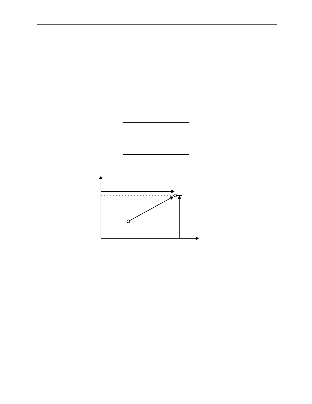
MotionSuite ™ Series Machine Controller Programming Manual Chapter 2: Motion Commands
2.2.2 Incremental (INC) Mode
!
! Outline
!!
The incremental (INC) mode commands the axial motion coordinate terms as the
incremental value from the current position of the work coordinate. Once the INC mode
command is designated, it remains until the next absolute (ABS) mode command is
designated. When the power supply is connected, it defaults the ABS mode command.
!
! Detailed Explanation
!!
The designating method of the INC mode command is shown as follows:
INC;
Or,
INC MOV [axis1]— ;
axis2
[axis1]
Designated position
[axis2]
Current position
(0,0)
axis1
Figure 2.26: Incremental Value of the Work Coordinate
!
! Program Example
!!
The program example of the INC mode command is shown as follows:
INC MOV [axis1]100 [axis2]200;
MOV [axis1]50 [axis2]100;
MOV [axis1]100;
MOV[axis2]50;
2-34
Page 76

MotionSuite ™ Series Machine Controller Programming Manual Chapter 2: Motion Commands
axis2
350
300
200
Starting position
0
100
250150
Figure 2.27: Program Example of the INC Mode Command
axis1
2-35
Page 77

MotionSuite ™ Series Machine Controller Programming Manual Chapter 2: Motion Commands
2.2.3 Current Value Chan ge (P OS)
!
CAUTION
Use caution when using the Current Value Change (POS) command.
The current value change (POS) command creates new “work
coordinate values.” If the POS command is designated
incorrectly, the moving actions will be totally different than expected.
Therefore, before operation,
coordinate values” are designated.
Forgetting this verification carries a risk of tool damage, as well as
bodily injury due to interference.
!
! Outline
!!
The current value change (POS) command creates a new coordinate by rewriting the
current position to the desired coordinate value. In this manual, this newly created
coordinate is called the work coordinate. The moving command designated after the POS
command moves on the work coordinate.
CHECK
that the correct “work
!
! Detailed Explanation
!!
The designating method of the POS command is shown as follows:
POS [axis1]—[axis2]—•••;
Desired coordinate value
2-36
Page 78

MotionSuite ™ Series Machine Controller Programming Manual Chapter 2: Motion Commands
axis2
(0,0)
axis2
(0,0)
Y
axis1
Work coordinate
Current pos ition
axis2
axis1
axis1
Figure 2.28: POS Command (current value change)
• The work coordinate based on the POS command can be switched as many times as
desired. Set the machine coordinate first. The POS command does not affect the
machine coordinate.
• Up to 14 axes can be designated by the POS command. An axis for which the
designation is omitted cannot rewrite the current value.
• If the moving command on the work coordinate exceeds the maximum designation value
after converting the machine coordinate, it cannot be designated.
• The setting status of the machine coordinate and work coordinate are shown in the
following table.
Product Status Incremental Detection System Absolute Detection System
After the power supply is connected
After execution of zero-point return
(ZRN)
After execution of the POS command
After operation of the zero-point setting
Machi n e co o r din at e:
Temporary setting *a
Work coordinate:
Cancel *c
Machi n e co o r din at e:
Setting
Work coordinate:
Cancel
Work coordinate:
Setting
Work coordinate:
Cancel
2-37
Machine coordinate:
Yes *b
Work coordinate:
Cancel
Work coordinate:
Cancel
Work coordinate:
Setting
Machine coordinate:
Setting
Work coordinate:
Cancel
Page 79

MotionSuite ™ Series Machine Controller Programming Manual Chapter 2: Motion Commands
a. Temporary setting
Sets up the machine coordinate whose zero-point is the current position after the
power supply is connected. After this, the soft limit function is disabled if the
zero-point return is not executed.
b. Yes
Creates the machine coordinate by the position data from absolute value
detection encoder.
c. Cancel
Cancels the work coordinate which was previous ly set; it is equal to the machine
coordinate.
2-38
Page 80

MotionSuite ™ Series Machine Controller Programming Manual Chapter 2: Motion Commands
2.2.4 Coordinate Plane Designation (PLN)
!
! Outline
!!
The coordinate plane designation command defines 2 logical axes set up in the parameters
as the coordinate plane. Before executing the coordinate plane designation command, the
coordinate plane must be designated.
Once the coordinate plane is designated, it is enabled until the next definition or the end of
the program.
!
! Detailed Explanation
!!
The designating method of the PLN command is shown as follows:
Horizontal axis
PLN
!
! Program Example
!!
The program example of the PLN command is shown as follows:
PLN [A][B]; (designate the plane structured by A and B axis)
MCW [A]50 [B]50 R50 F1000;
Starting position: A = B = 0
B
50
[axis1]
Designate 2 axes on
the coordinate plane
Vertical axis
[axis2];
(0,0)
Figure 2.29: Program Example of the Coordinate Plane Designation (PLN)
2-39
50
A
Page 81

MotionSuite ™ Series Machine Controller Programming Manual Chapter 2: Motion Commands
2.2.5 Machine Coordinate Command (MVM)
!
CAUTION
The machine coordinate (MVM) command temporarily locates the
coordinate position on the “machine coordinate”. If the MVM
command is designated without confirming the zero-point position of
the “machine coordinate,” unexpected movement will occur.
Therefore, before operation,
“machine coordinate” is designated.
Forgetting this verification carries a risk of tool damage, as well as
bodily injury due to interference.
!
! Outline
!!
The machine coordinate command (MVM) is used when attempting to temporarily move
the machine coordinate, after the work coordinate has been set up differently than the
machine coordinate by the current value change (POS) command.
From the next designation, move temporarily to the absolute coordinate position by the
positioning (MOV) command or linear interpolation (MVS) command. This command
operates in the ABS mode, regardless of ABS/INC mode designation.
The MVM command is only enabled in the designated block. For example, it sets up the
movement on the work coordinate by the linear interpolation (MVS) command in the
following block. Refer to the following figure.
CHECK
that the correct position on the
!
! Detailed Explanation
!!
The designation method of the MVM command is shown as follows:
MVM MOV •• •;
Or,
MVM MVS •••;
!
! Program Example
!!
The program example of the MVM command is shown as follows:
MVM MVS [axis1]50 [axis2]50 F1000;
2-40
Page 82

MotionSuite ™ Series Machine Controller Programming Manual Chapter 2: Motion Commands
axis2
axis2
250
150
100
(0,0) Work coor dinate
0
50
MVS [axis1]50 [axis2]50 F1000;
axis1
150100
Machine coordinate
axis1
Figure 2.30: Program Example of the Machine Coordinate Command (MVM)
2-41
Page 83

MotionSuite ™ Series Machine Controller Programming Manual Chapter 2: Motion Commands
2.2.6 Program Current Position Update (PLD)
!
! Outline
!!
During the motion program operation, when an axis is moved by programs other than the
motion program (such as JOG motion, STE P motion, or when an axis is moved by the us er
functions), the “program current position” does not move. In this case, if the program
continues to execute the motion program, the axis moves only to the position at which the
moving amount is manually shifted. In order to solve this problem, the PLD command is
used to update the “program current position.”
This command does not correspond to the block operation. In other words, it is not a
command which can be stopped by the block operation mode.
!
! Designating Methods
!!
[axis1] [a x i s 2 ]... [axis];
PLD
!
! Program Example
!!
During manual operation of the motion program:
MPM001 “GROUP1”
MOV [axis1] 1000; ← Here, [axis1] is moved by JOG.
PLD [axis1]; ← the “program current position” is updated.
MOV [axis1] – 1000;
When the axis is moved by the motion program user functions:
MPM001 “GROUP1”
MOV [axis1] 1000;
UFC FNC10 MB00000 IW00100 MB00020
←
[axis1] is moved by the user functions.
PLD [axis1]; ← the “program current position” is updated.
MOV [axis1] – 1000;
Supplement
The PLD command is executed depending on the user’s needs. Sometimes, even though
manual movement applies during motion program operation, the PLD command is not
used.
2-42
Page 84

MotionSuite ™ Series Machine Controller Programming Manual Chapter 2: Motion Commands
2.2.7 Timed Wait (TIM)
!
! Outline
!!
The timed wait (TIM) command is used to enter the next block after waiting the time
designated by the character (T), from the next designation.
The TIM command cannot be designated simultaneously with other commands.
!
! Detailed Explanation
!!
The designating method of the TIM command is shown as follows:
TIM T—;
Waiting time
The possible range that the (T) can designate is 0.01 ~ 599.99 [sec].
• When the time (T) is designated by the integer number, 1 = 0.01 [sec]. The position of
the decimal does not affect the parameter setting.
!
! Program Example
!!
The program example of the TIM command is shown as follows:
MOV [axis1]100;
TIM T250;
2.5sec
Execute the [TIM] command after the positioning is completed.
v
MOV
2.5sec
Next block
t
Figure 2.31: Program Example of the Timed Wait (TIM) Command
2-43
Page 85

MotionSuite ™ Series Machine Controller Programming Manual Chapter 2: Motion Commands
2.2.8 Program End (END)
!
! Outline
!!
The program end (END) command ends program operation. In this block, it cannot be
designated simultaneously with other commands.
!
! Detailed Explanation
!!
The designating method of the END command is shown as follows:
END;
The program ends
According to this command, after the block execution is finished, the program
operation is ended.
• When the previous block is designated by a moving command, the program operation is ended after the in-position check is finished.
2-44
Page 86

MotionSuite™ Series Machine Controller Programming Manual Chapter 3: Advanced Programming Methods
3 Advanced Programming
This chapter explains how to program motion control commands including
advanced control commands, and speed/acceleration commands.
3.1 Ad v an c e d Co n t rol Comman d s ... .................. ......................... .................. ............ 3-2
3.1.1 In-Pos ition Check (PFN) Co m m a n d ........... ................... ........................ .... 3-2
3.1.2 Second In-Position Check (INP) Command . ............................................. 3-5
3.1.3 Ignore Single Block (SNG) Command ...................................................... 3-7
3.1.4 User Function Call-out (UFC) Command ................................................. 3-8
3.1.5 I/O Vari ab le Wait (IOW) Co mmand ........ ................... .................. .......... 3-17
3.1.6 Sub-p rog ram Call -o u t (MSEE) Co m m a n d ........................ ...................... 3-18
3.1.7 Sub-program End (RET) Command ........................................................ 3-19
3.1.8 1-scan Wait (EOX) Command ................................................................. 3-20
3.1.9 Branc h (IF ELSE IEND ) Command ..... ...... ................... ........................ .. 3-22
3.1.10 Re p e at (W H I LE WEND ) Co m m a n d ........................... ........................ .... 3-24
3.1.11 Parallel Execution (PFORK, JOINTO, PJOINT) Command .................. 3-26
3.1.12 Selec ti v e Execut i o n (S FORK, JOIN TO, SJOI N T) Comman d ................ 3-31
3.2 Speed/Acceleration Commands ........................................................................ 3-34
3.2.1 Accelera t i o n Ti me Change (A CC) Comma n d ........................ .................3-34
3.2.2 S-Curve Time Constant Change (SCC) Command .................................3-36
3.2.3 Feed Sp ee d Ch an g e (V EL) Comm a n d ...... ................... .................. .......... 3-38
3.2.4 Interpolation Feed Speed Ratio Setting (IFP) Command ........................ 3-40
3.2.5 Maximum Interpolation Feed Speed Setting (FMX) Command ............. 3-42
3.2.6 Interpolation Acceleration Time Change (IAC) Command .................... 3-44
3.2.7 Interpolation Deceleration Time Change (IDC) Command .................... 3-46
3-1
Page 87

MotionSuite™ Series Machine Controller Programming Manual Chapter 3: Advanced Programming Methods
3.1 Advanced Control Comman ds
In this section, the details of programming methods for advanced commands within the
motion control commands are explained. Since they are comparatively complicated,
beginners should skip this section and go to item 1.2 Motion Programing Method.
3.1.1 In-Position Check (PFN) C o mmand
!
! Outline
!!
During interpolation command movement, after an axis feed is complete, the In-position
Check (PFN*) command waits until the axis has entered the In-position Check Range.
When it enters the In-position Check Range, the next block is executed.
During interpolation command corner movement, this command is used to pass the
designated end position.
With PFN Command
Without PF N com m and
(pas ses close to the
en d p o sition)
(passes the end position)
!
! Detailed Explanation
!!
There are two designating methods for the PFN command.
a) When designating to the block simultaneously with the interpolation
commands
MVS [axis1]100.[axis2]200.F1000PFN;
Execute the In-position Check for the axis designated by the MVS command,
then proceed to the next block.
b) When designating independently
PFN [axi s1] [a xis2] ;
MOV [axis1 ] - [a x is2]-;
*
In-position Check (PFN)
completion range after the designated block movement starts deceleration.
: A function that detects if an axis has entered the positioning
3-2
Page 88

MotionSuite™ Series Machine Controller Programming Manual Chapter 3: Advanced Programming Methods
If axis1 and axis2 enter the In-position Check, the next block is executed.
According to the above command, the In-position Check is executed to verify if the axis
movement in the block before the PFN command has entered the Positioning Completion
Range, then the next block execution is started.
Speed
Actual Axis Movement
Comm a nd P u ls e
Positioning Completion Range
In-Positi on Check Start
Next Block Command
Time
Figure 3.1: In-position Check Process
• The Positioning Completion Range is set up in each servopack user parameter.
• Cn-001B Positioning Completion Width
• As indicated below, two methods are available for the PFN command: a command
designated simultaneously with the interpolation commands, and a command
designated independently to the block in which the In-position Check is executed.
Designation Type Designating Method
Designated for the same
1
block as the interpolation
commands
Independent designation
2
Axis Designation
MVS[axis1]100.
[axis2]200. F1000 P F N
PFN [axis 1] [a xis 2]
3-3
Notes
In-position check for the axis
designate d with the MVS commands,
;
then proceeds to the next block.
In-position check for the designated
axis (check i f the axis ca n be us ed) the n
proceeds to the next block.
Page 89

MotionSuite™ Series Machine Controller Programming Manual Chapter 3: Advanced Programming Methods
! Program Examples
MVS [axis 1] 200. F100 PFN; Linear Interpolation Movement Completion Wait
MOV [axis1] 400. [axis2] 400; Movement according to the positioning
Speed
MVS Command Movement
MOV Command Movement
Time
Positioning Completion
Figure 3.2: In-position Check (PFN)
Supplement
When the PFN command is not sent, next block execution is started after MVS command
pulse distribution is complete.
3-4
Page 90

MotionSuite™ Series Machine Controller Programming Manual Chapter 3: Advanced Programming Methods
3.1.2 Second In-Position Check (INP) Comma nd
! Outline
When moving according to the interpolation, the Second In-position Check (INP)
command is sent to pass close to the end position.
Axis 2
Axis 1
Interpolation locus
when the In-position
Check command is
not sent.
Figure 3.3: Second In-position Check Command
! Detailed Explanation
The INP command method is shown as follows:
INP [axis1]--[axis2 ]--...;
Positioning Completion Range
According to the above command, when the PFN-designated interpolation movements
which are commanded after the INP command, and/or the independent PFNdesignated interpolation movements are verified having entered the Second
Positioning Completion Range, the next block execution is started. When there are
multiple moving axes, the next block is started after each axis has entered the Second
Positioning Completion Range.
Sharp angles occur when
using the PFN command
w/o the INP command.
The locus is rounded
w/ the P FN command
after the INP command.
Speed
Actual Interp olation Movement
Command pulse
Start In-Position Check
Second Positioning Completion Range
(Set according to program)
Figure 3.4: Second In-Position Check Command Method
3-5
Next Block
Time
Page 91

MotionSuite™ Series Machine Controller Programming Manual Chapter 3: Advanced Programming Methods
• A range for Second Positioning Completion Range setting is as indicated below:
1 ~ 65535[Command Units]
However, as indicated in the diagram above, the Second In-position Check is started at
the time that the pulse distribution of the commanded block is complete. Therefore, if
a very large value is set in the Second Positioning Completion Range, the Second Inposition Check completes at the deceleration start point, and then proceeds to the next
block.
• Once the INP command is set up, the Second In-position Check is valid for all
interpolation commands until cancellation.
• For cancellation of the Second In-position Check, give the [0] command to the axis to be
cancelled in the Second Positioning Completion Range. Only the axis receiving the [0]
command will be cancelled.
• It is now possible to send the In-position Check (PFN) command. When the command is
sent, the In-position Check will occur according to the parameter “Positioning
Completion Range” in spite of the Second Positioning Completion Range.
! Program Examples
ABS MOV [axis 1]0[axis2]0; Zero-point positioning
INP [axis 1](a)[axis2](b); Second Positioning Completion Range set-up
MVS [axis1]100) PFN; X-axis direction / Linear interpolation
MVS [axis2]100 PFN; Y axis direction / Linear interpolation
MVS [axis1]-100 PFN; X axis direction / Linear interpolation
+axis2
100
(b)
+axis1
-100
(0,0)
100
(a)
Figure 3.5: Program Example of the Second In-position Check
3-6
Page 92

MotionSuite™ Series Machine Controller Programming Manual Chapter 3: Advanced Programming Methods
3.1.3 Ignore Single Block (SNG) Command
! Outline
The Ignore Single Block (SNG) command is used when continuous operation is needed
for a special block, during the operation of the Single Block Operating Mode*.
! Detailed Explanation
The SNG command method is shown as follows:
SNG: Axis Movement Command
and
SNG: No Axis Movement Command
According to the above command, even when the Single Block Operating Mode is in
effect, continuous operation will take place within the block described by the SNG command without single block stoppage.
• For commands other than the axis movement and speed/acceleration, the single block
operation cannot be executed. Therefore, it would be meaningless to use these
commands with the SNG command.
• The commands which can be designated by the SNG command are shown as follows:
MOV, MVS, MCW, MCC, ZRN, S K P, MVT,
EXM, ACC, SCC, PFN, VEL, INP, EOX
! Program Examples
MVS [axis1]0[axis2]0;
SNG MVS[axis1]100[axis2]200;
#MB000101=1;
#MB000102=1;
#MB000103=1;
Even in the single block operating mode, continuous operation occurs.
*
Single Block Operating Mode
stoppage occurs in each block. However, the commands other than the axis movement and
speed/acceleration commands cannot perform the single block stoppage. Moreover, use
caution when operating, because each block stoppage in the single block operation
occurring in parallel will change according to motion program content.
: With the Single Block Operating Mode, single block
3-7
Page 93

MotionSuite™ Series Machine Controller Programming Manual Chapter 3: Advanced Programming Methods
3.1.4 User Function Call-out (UFC) Command
! Outline
The User Function Call-out (UFC) command calls up and executes the functions created
by the user, by designating the function name.
! Detailed Explanation
The UFC command method is shown as follows:
UFC Function Name, Input Data, Input Address, and Output Data
Function Name
Input Data
Input Address
Output Data
:
ASCII 8 bytes
:
Up to 16 bits
:
Up to 1 addresses
:
Up to 16 bits (1 bit is always needed)
Note: Input data and input address can be omitted.
The output data means that there is no input data. It always requires a
minimum of 1.
According to the above command, the user functions are called out. When the execution
of the user functions is finished, execution proceeds to the block following the UFC.
! Program Examples
UFC KANSUU MB00000 IW0010 MB00020, MA00100 ,
Function Name Input Data Input Address
MB00001 MW00200 ML00201;
Output Data
MB0000
Function Name
MB0000
INPUT-1 OUTPUT-1
IW0010
MB0002
INPUT-2 OUTPUT-2
INPUT-3 OUTPUT-3
INPUT-4
MA00100
MW00201
ML00201
Figure 3.6: Program Example of the User Function Call-out (UFC)
3-8
Page 94

MotionSuite™ Series Machine Controller Programming Manual Chapter 3: Advanced Programming Methods
! UFC Command Creating Steps
UFC command creating steps are described below.
Determine UFC command specifications.
Set up the following in the DWG
configuration definition screen:
• Function configuration definition
• Input/Output definitions
Create the user functions (ladder).
Create the motion program.
Verify motion
• Determine input/output number and data type.
• Determine function name.
Input by using the CP-717.
Use the same method as the DWG creation.
However, the register type to be used varies.
Create with the format of the UFC:
Function name, Input data, Input address,
and Output data.
! Register Type Used in the User Function
The types of the register are shown as follows:
• B-VAL
• I-VAL
• L-VAL
• I-REG
• L-REG
→
Bit-type
→
For fut u re use
For fut u re use
→
Integer number type
→
32-bit integer or real number-type
→
3-9
Page 95

MotionSuite™ Series Machine Controller Programming Manual Chapter 3: Advanced Programming Methods
! Relationship Between the I/O Regis ter and Function Register
The following illustration shows the interaction between the I/O register designated by the
UFC command and the function register.
Input Function Register Output
MA00100
Bit-type data inpu t
B-VAL
(Up to 16 bit s )
I-REG
L-REG input
(Up to 16 words)
Address Input
MW00100
MW00101
MW00102
MW00103
MW00104
X Register
(Inp ut R egi st e r)
XB000000~XB00000F
XW0001
XW0002
XW0003
XW0004
•
•
•
•
•
•
•
•
XW00014
XW00016
A Register
XW00014
XW00016
XW00014
XW00016
XW00014
Y Register
(Output Register)
YB000000~YB00000F
YW0001
YW0002
YW0003
YW0004
•
•
•
•
•
•
•
•
YW00014
YW00016
Bit-type da ta output
B-VAL
I-REG
L-REG Output
Z Register # Register D Register
Figure 3.7: I/O Register and Function Register Relationship
Supplement
The S, M, I, O, and C registers are used in the same way as the DWG registers.
3-10
Page 96

MotionSuite™ Series Machine Controller Programming Manual Chapter 3: Advanced Programming Methods
Each user function can use the 11 registers shown in the table below.
Function Register
Type Name
Functional input
X
register
Functional output
Y
register
Functional internal
Z
register
Functional external
A
register
## Register
DD Register
Command
Method
XB, XW,
XL,
XFnnnnn
YB, YW,
YL,
YFnnnnn
ZB, ZW, ZL,
ZFnnnnn
AB, AW,
AL,
AFnnnnn
#B, #W, #L,
#Fnnnnn
(#Annnnn)
DB, DW,
DL,
DFnnnnn
(DAnnnnn)
Content
Function Input:
• Bit input: XB000000~XB00000F
• Integer input: XW000001~XW00016
• Double-length integer input:
XL00001~XL00015
The register number nnnnn is displayed
with a decimal.
Function Input:
• Bit input: YB000000~YB00000F
• Integer input: YW000001~YW00016
• Double-length integer input:
YL00001~YL00015
The register number nnnnn is displayed
with a decimal.
Internal register owned by each function.
It can be u sed as an internal pr o cess for th e
function.
The register number nnnnn is displayed with a
decimal
External regis ter whose base address is
address input value.
It can be used for linking to (S, M, I, O, #,
Dannnnn).
The register number nnnnn is displayed
with decima l.
Register that only can be referenced in a
program.
Only the corresponding DWG can be referred.
The actual range is designated in
MotionWorks™ by the user.Th e reg ister
number nnnnn is disp layed with a decimal.
Register that is owned by ea ch DWG.
Only the corresponding DWG can be referred.
The actual range is designated in MotionWorks™ by the user.
The register number nnnnn is displayed with a
decimal.
Characteristic
Individual
Functions
3-11
Page 97

MotionSuite™ Series Machine Controller Programming Manual Chapter 3: Advanced Programming Methods
Function Register (Continued)
SB, SW, SL,
S System Register
M D ata Register
I Input Register
O Output Register
C Constant Register
SFnnnnn
(SAnnnnn)
MB, MW,
ML,
MFnnnnn
(MAnnnnn)
IB, IW, IL,
IFhhhh
(IAhhhh)
OB, OW,
OL,
Ofhhhh
(OAhhhh)
CB, CW,
CL,
CFhhhhh
(CAnnnnn)
Same as the DWG registers.
Becau se th e s e re g i ste r s ar e th e s a me as the
DWG registers, use cauti on when re ferencing
the same function from a DWG that has a
different priority level.
Same as
the DWG
registers.
Note: Even within the functions, the SA, MA, IA, OA, DA, #A, CA can still be used.
3-12
Page 98

MotionSuite™ Series Machine Controller Programming Manual Chapter 3: Advanced Programming Methods
An example of the input/output register delivery is shown as follows:
Motion program description
UFC TESTFUN C DB 00000 DB000001 MW00030 MW00032 MA00100, DB0000002 MW00040
MA00100
DB000000
DB000001
MW00032
MW00032
MW00000
MW00001
MW00002
•
•
•
•
•
•
•
•
X Register
Y Register
XW00000
XW00001
XW00002
XW00016
AW00000
AW00001
AW00002
•
•
•
•
•
•
•
•
YW00000
YW00001
YW00002
YW00015
Figure 3.8: Motion Program Description
DB000002
MW00040
! User Function Creation
The steps for creating a user function are described with the example shown below .
Designate servo axis number and speed data,
Specifications
Motion program
To create a user function, follow the steps below:
a. In the File Manager screen, open [Programs → Function Programs], right-click
then set them up in the parameter [Fast feed
speed OLxx22].
MW00030 = Servo axis number (1 or 2)
ML00032 = Fast feed speed
UFL FUNC-T1 MW00030 ML00032, DB000001;
3-13
Page 99

MotionSuite™ Series Machine Controller Programming Manual Chapter 3: Advanced Programming Methods
on Function Programs, then double-click on the [Make New DWG (N)].
b. Set up DWG name and type in the message box [Input DWG Name], then click
on the OK button.
c. The ladder screen (empty screen) appear s. Selec t
Program (P) → Property (R)
. The DWG Configuration screen is opened.
3-14
File (F) → Open (O) →
Page 100

MotionSuite™ Series Machine Controller Programming Manual Chapter 3: Advanced Programming Methods
d. Set up the number of the D register in the Function Configuration of the DWG
Configuration screen. (The default value is 32.)
e. Click on the I/O Definition tab, then set up the input/output number and data
type of the function.
Example: In the case of UFC FUNC-T1 MW00030 ML00032,DB000001, the
setting is as follows.
3-15
 Loading...