

Yamaha MU-100 Service Manual
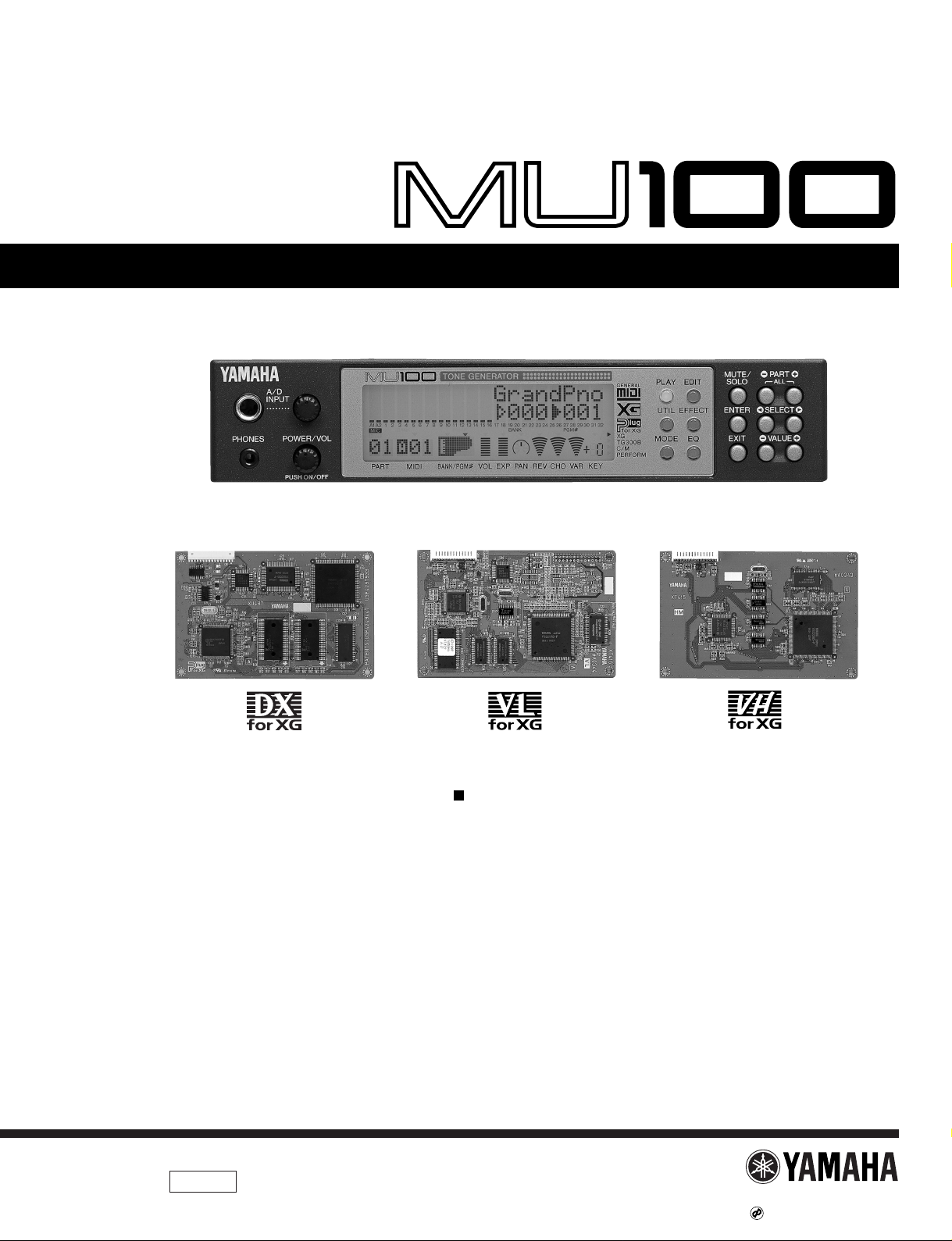
SERVICE MANUAL
TONE GENERATOR
CONTENTS
SPECIFICATIONS
···································································································
3
PANEL LAYOUT
·······································································································
4
CIRCUIT BOARD LAYOUT
···············································································
5
BLOCK DIAGRAM
···································································································
6
DISASSEMBLY PROCEDURE
·······································································
7
LSI PIN DESCRIPTION
····················································································
12
IC BLOCK DIAGRAM
·························································································
14
CIRCUIT BOARDS
·······························································································
16
TEST PROGRAM
··································································································
18
MIDI / COMPUTER CONNECTING CABLES
····································
23
ERROR MESSAGES
··························································································
24
INITIALIZE
·················································································································
25
MIDI IMPLEMENTATION CHART
······························································
26
OVERALL CIRCUIT DIAGRAM
···································································
27
PARTS LIST
SY
011450
PLG-100DX PLG-100VL PLG-100VH
HAMAMATSU, JAPAN
0.32K-3942 Printed in Japan '99.01
MU100
2
WARNING: CHEMICAL CONTENT NOTICE!
The solder used in the production of this product contains LEAD. In addition, other electrical/electronic and/or plastic (where
applicable) components may also contain traces of chemicals found by the California Health and Welfare Agency (and possibly
other entities) to cause cancer and/or birth defects or other reproductive harm.
DO NOT PLACE SOLDER, ELECTRICAL/ELECTRONIC OR PLASTIC COMPONENTS IN YOUR MOUTH FOR ANY REASON
WHAT SO EVER!
Avoid prolonged, unprotected contact between solder and your skin! When soldering, do not inhale solder fumes or expose eyes
to solder/flux vapor!
If you come in contact with solder or components located inside the enclosure of this product, wash your hands before handling
food.
LITHIUM BATTERY HANDLING
This product uses a lithium battery for memory back-up.
WARNING: Lithium batteries are dangerous because they can be exploded by improper handling. Observe the following
precautions when handling or replacing lithium batteries.
Leave lithium battery replacement to qualified service personnel.
Always replace with batteries of the same type.
When installing on the PC board by soldering, solder using the connection terminals provided on the battery cells.
Never solder directly to the cells. Perform the soldering as quickly as possible.
Never reverse the battery polarities when installing.
Do not short the batteries.
Do not attempt to recharge these batteries.
Do not disassemble the batteries.
Never heat batteries or throw them into fire.
ADVARSEL!
Lithiumbatteri-Eksplosionsfare ved fejlagtig håndtering. Udskiftning må kun ske med batteri af samme fabrikat og type. Levér det
brugte batteri tilbage til leverandøren.
VARNING
Explosionsfara vid felaktigt batteribyte.
Använd samma batterityp eller en ekvivalent typ som rekommenderas av apparattillverkaren.
Kassera använt batteri enligt fabrikantens instruktion.
VAROITUS
Paristo voi räjähtää, jos se on virheellisesti asennettu.
Vaihda paristo ainoastaan laitevalmistajan suosittelemaan tyyppiin.
Hävitä käytetty paristo valmistajan ohjeiden mukaisesti.
The following information complies with Dutch Official Gazette 1995. 45; ESSENTIALS OF ORDER ON THE COLLECTION OF
BATTERIES.
•Please refer to the diassembly procedure for the removal of Back-up Battery.
•Leest u voor het verwijderen van de backup batterij deze beschrijving.
IMPORTANT NOTICE
This manual has been provided for the use of authorized Yamaha Retailers and their service personnel. It has been assumed that
basic service procedures inherent to the industry, and more specifically Yamaha Products, are already known and understood by
the users, and have therefore not been restated.
WARNING: Failure to follow appropriate service and safety procedures when servicing this product may result in personal
injury, destruction of expensive components and failure of the product to perform as specified. For these
reasons, we advise all Yamaha product owners that all service required should be performed by an authorized
Yamaha Retailer or the appointed service representative.
IMPORTANT: This presentation or sale of this manual to any individual or firm does not constitute authorization, certification,
recognition of any applicable technical capabilities, or establish a principal-agent relationship of any form.
The data provided is belived to be accurate and applicable to the unit(s) indicated on the cover. The research engineering, and
service departments of Yamaha are continually striving to improve Yamaha products. Modifications are, therefore, inevitable and
changes in specification are subject to change without notice or obligation to retrofit. Should any discrepancy appear to exist,
please contact the distributor's Service Division.
WARNING: Static discharges can destroy expensive components. Discharge any static electricity you body may have
accumulated by grounding yourself to the ground buss in the unit (heavy gauge black wires connect to this
buss.)
IMPORTANT: Turn the unit OFF during disassembly and parts replacement. Recheck all work before you apply power to the
unit.

SPECIFICATIONS
MU100
3
Tone Generation Method
AWM2 (Advanced Wave Memory 2)
Maximum Simultaneous Polyphony
64-note
Sound Module Modes
XG, TG300B, C/M, and Performance
Multi-timbral Capacity
32-Part (on 32 MIDI channels; with element reserve priority for later notes and dynamic Voice allocation)
Internal Voice/Program Structure
Normal Programs
Total Voices···································· 1267
XG mode········································· 1074
TG300B mode ································ 614
C/M mode······································· 128 (Parts 1 — 9), 64 (Parts 11 — 16)
Drum Programs
Total Kits········································ 46
XG mode········································· 36
TG300B mode ································ 10
C/M mode······································· 1
Performance Programs
Up to four Voices plus all effect settings can be memorized to a Performance.
Preset Programs······························ 100
User Programs ································ 100
Effects
Six sections of multi-effects: Reverb (12 Types), Chorus (14 Types),
Variation (70 Types), Insertion 1, 2 (43 Types), Multi EQ (4 Types), and Part EQ (1 Type)
Display
Custom back-lit LCD
Controls
POWER/VOL control, A/D INPUT level control; Mode select buttons: PLAY, UTIL (UTILITY), MODE, EDIT, EFFECT, EQ; other buttons:
MUTE/SOLO, ENTER, EXIT, PART
,
SELECT , VALUE
Jacks and Terminals
Front panel: PHONES jack (Stereo Mini-pin), A/D INPUT (stereo 1/4” plug)
Rear panel: OUTPUT R,L (RCA-pin), INPUT R, L (RCA-pin); DC IN jack; TO HOST terminal; HOST SELECT switch; MIDI IN-A/B, MIDI OUT
and MIDI THRU terminals
Computer/MIDI Interface
Direct connection to host computer port (RS-232C, RS-422); MIDI terminals allow connection to MIDI sequencer or MIDI controller
Data Transfer (Baud) Rate
MIDI — 31,250 bps (bits per second)
Mac — 31,250 bps
PC-1 — 31,250 bps
PC-2 — 38,400 bps
Power Supply
Yamaha PA-5B AC Adaptor (included)
Dimensions (W X D X H)
220 X 210 X 44 mm (8-11/16" X 8-1/4" X 1-3/4")
Weight
1.3 kg (2 lbs., 14 oz.)
Included Accessories
Owner’s Manual, Yamaha PA-5B AC Adaptor,
XGtools Setup Guide, CD-ROM “XGtools”
Output Level
Refer to the TEST PROGRAM section of this manual on page,19 and 20.
MU100
4
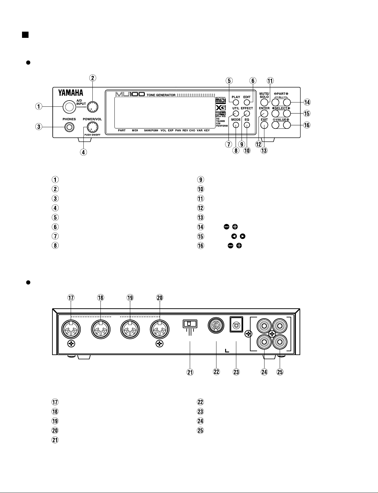
A/D INPUT
A/D INPUT level control
PHONES jack
POWER/VOL control
PLAY button
EDIT button
UTIL (UTILITY) button
MODE button
EQ button
MUTE / SOLO button
ENTER button
EXIT button
PART / buttons
SELECT / buttons
VALUE / buttons
EFFECT button
PANEL LAYOUT
Front Panel
MIDI THRU terminal
MIDI OUT terminal
MIDI IN-A terminal
MIDI IN-B terminal
HOST SELECT switch
TO HOST terminal
DC IN jack
OUTPUT L,R jacks (Left,Right)
INPUT L,R jacks (Left,Right)
MIDI
THRU
OUTOUT I N-AI N-A
I N-BI N-B
MIDIMIDI MacMac
PC-2PC-2 PC-1
HOST SELECT
TO HOSTTO HOST
DC INDC IN
SER NO.
R
L
OUTPUT INPUT
Rear Panel
MU100
5
CIRCUIT BOARD LAYOUT
DM
PSWPVR
Front panel
LCD
CN10
CN 7
1
CN 14
1
CN6
CN13
CN5
CN9
1
1
1
1
VR cable
(10P)
PSW cable
(2P)
SW2 cable
(7P)
SW1 cable
(10P)
LCD cable
CN1
1
CONTRAST
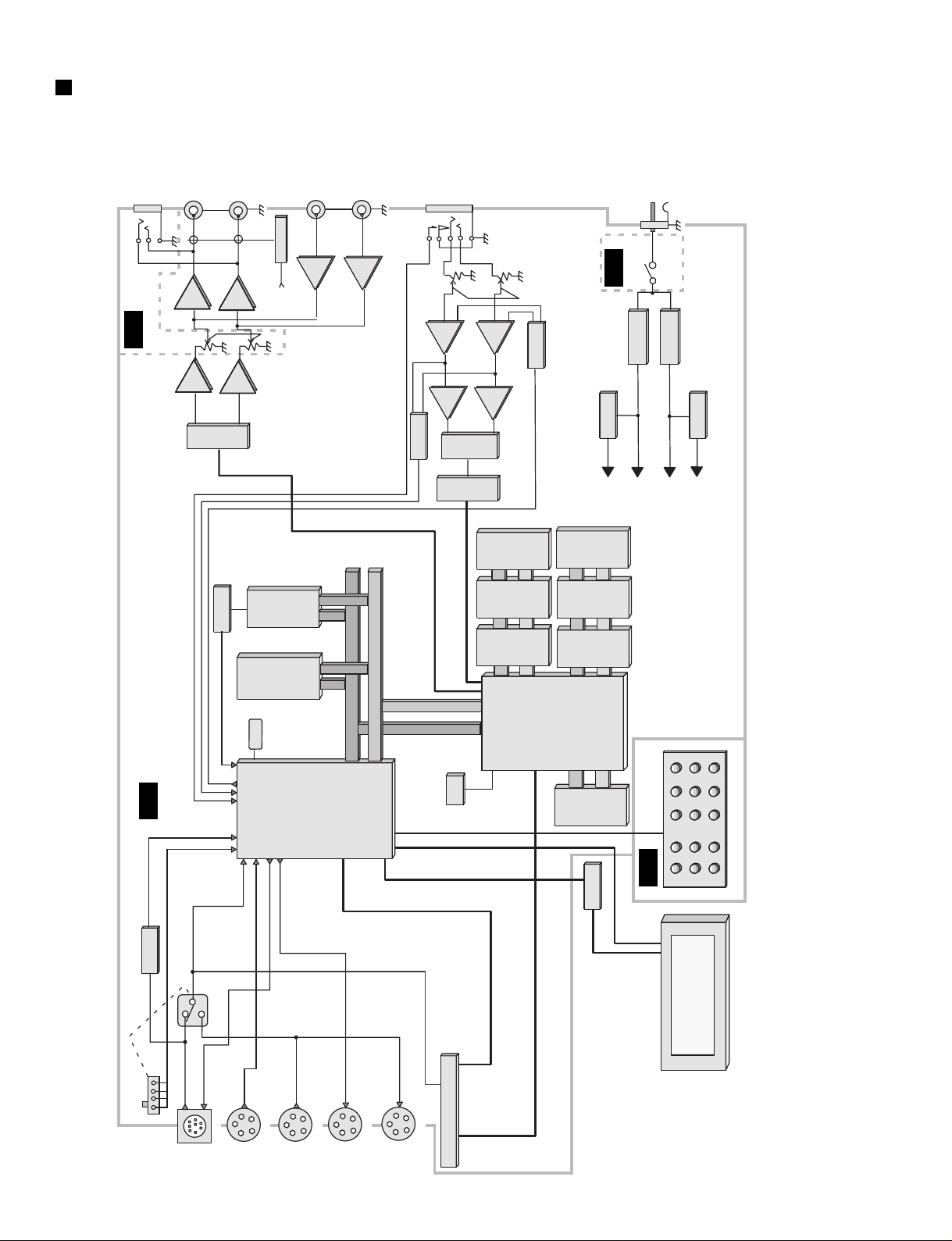
ADDRESS BUS
DATA BUS
16M
PROGRAM
(16bit)
1M
SRAM
(8bit)
32M
MASK
ROM
(16bit)
32M
MASK
ROM
(16bit)
4M
DRAM
(16bit)
SWP30
MPU
H8S
16MHz
33.8688
MHz
A/D INPUT
OUTPUT-L
OUTPUT-R
HEAD PHONE
PEAK
DETECT
MUTING
LPF
AMP
LPF
AMP
AMP
AMP
AMP
D/A
A/D
ANALOG
FRONT
END
GAIN
SELECT
9V
REGULATOR5VREGULATOR
5V
REGULATOR
3.3V
REGULATOR
AC-ADAPTOR
PA-5B
POWER SWITCH
MIDI-INB
MIDI-INA
MIDI-OUT
MIDI-THRU
TO-HOST
HOST-SELECT
OFF LINE
CHECK
PLUGIN BOARD CABLE
+5VA
+9VA
+5V
+3.3V
+9VA
AMP
INPUT VOL
MASTER VOL
LPF
LPF
INPUT-L
INPUT-R
32M
MASK
ROM
(16bit)
32M
MASK
ROM
(16bit)
16M
MASK
ROM
(16bit)
16M
MASK
ROM
(16bit)
DM
PVR
IC2
IC16
IC17
IC18
IC35
IC34
IC39
IC38
IC37
IC20
3
3
31
21
1
IC10
28CA1-8811650
1
IC8
IC9
IC36
IC29
IC30
IC21
62
21
12
26
13
75
13275
6
67
11 6
IC11
IC12
110
62
109
105
107
30 33
63
IC12
64 111
616059
PVR
PSW
BATTERY
PANEL SW
LCD UNIT
BACK UP
MU100
BLOCK DIAGRAM
MU100
6
MU100
7
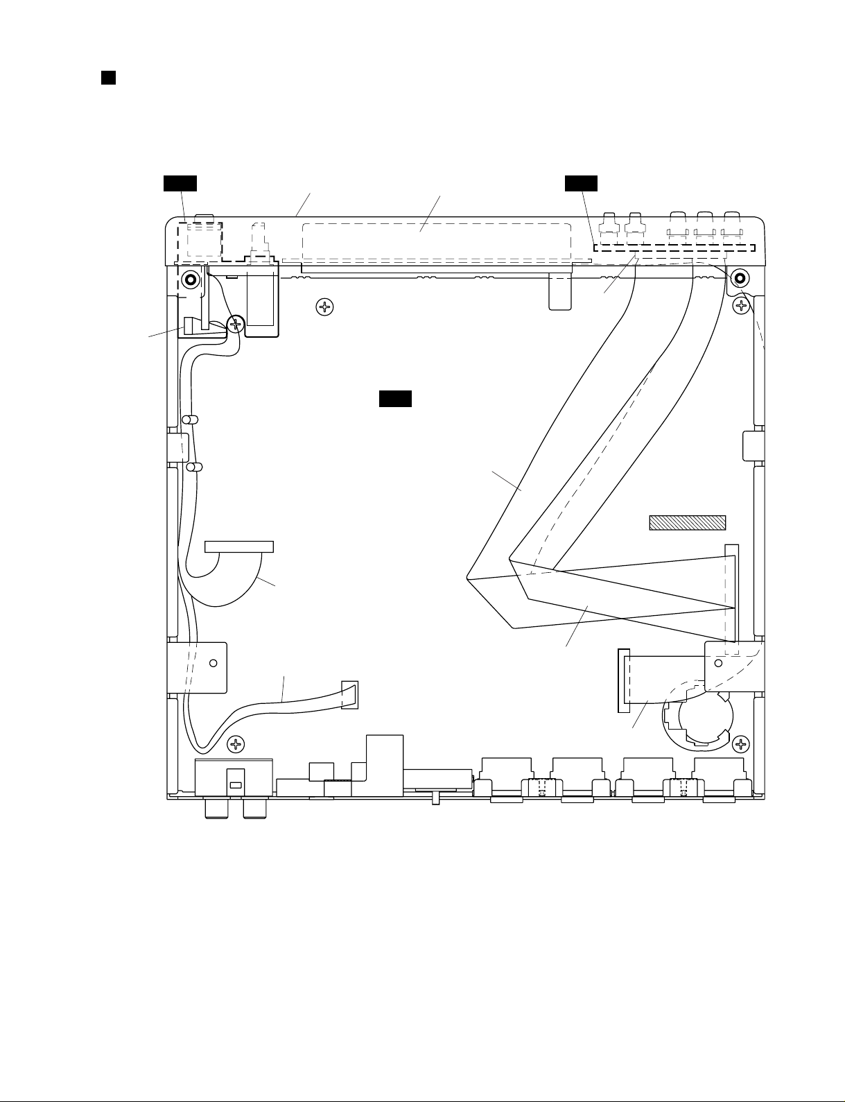
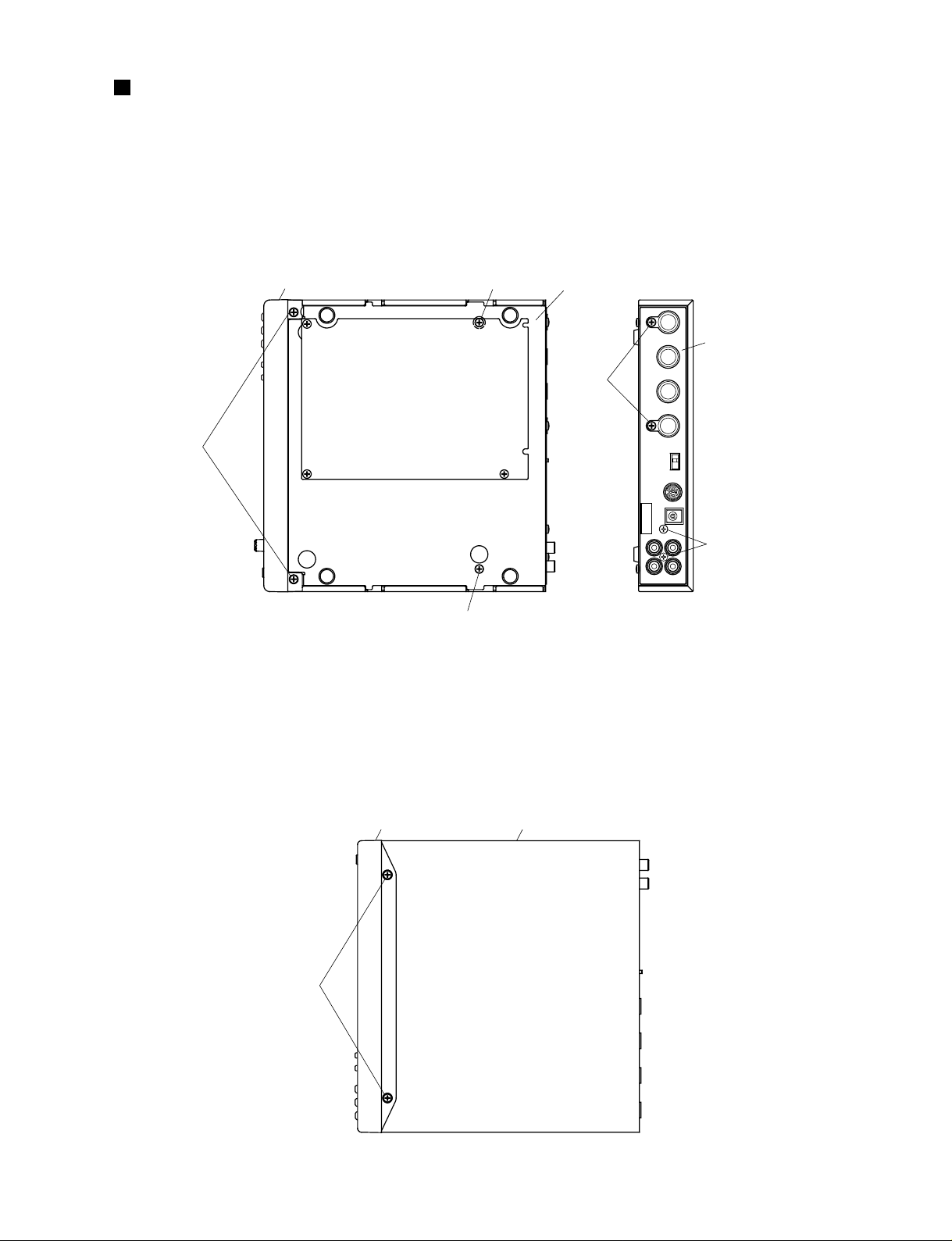
DISASSEMBLY PROCEDURE
1-1 Remove the four (4) screws marked [60], the screw
marked [75], the screw marked [76] and the two (2)
screws marked [80]. The bottom assembly can then
be removed. (Fig. 1)
*
When you reattach the bottom assembly, you should
tighten the screws in the order described in figure 1.
1. Bottom Assembly
Front assembly
Rear panel
[80]
[76]
[60]
[75]
[60]
[60]: Bind Head Tapping Screw-B 3.0X8 MFZN2BL (EP600190)
[75]: Bind Head Screw 3.0X6 MFZN2BL (EG330360)
[76]: Bind Head Screw 3.0X6 MFNI33 (EG330370)
[80]: Flat Head Tapping Screw-C 3.0X8 MFZN2BL (VR060800)(Fig.1)
Bottom assembly
7
8
6
4
1
3
2
5
2-1 Remove the bottom assembly. (See Procedure 1.)
2-2 Remove the two (2) screws marked [30]. The top
assembly can then be removed from the front
assembly. (Fig. 2)
2. DM Circuit Board
Front assembly
[30]
[30]: Flat Head Tapping Screw-C 3.0X8 MFZN2BL (VR060800)(Fig.2)
Top assembly
MU100
8
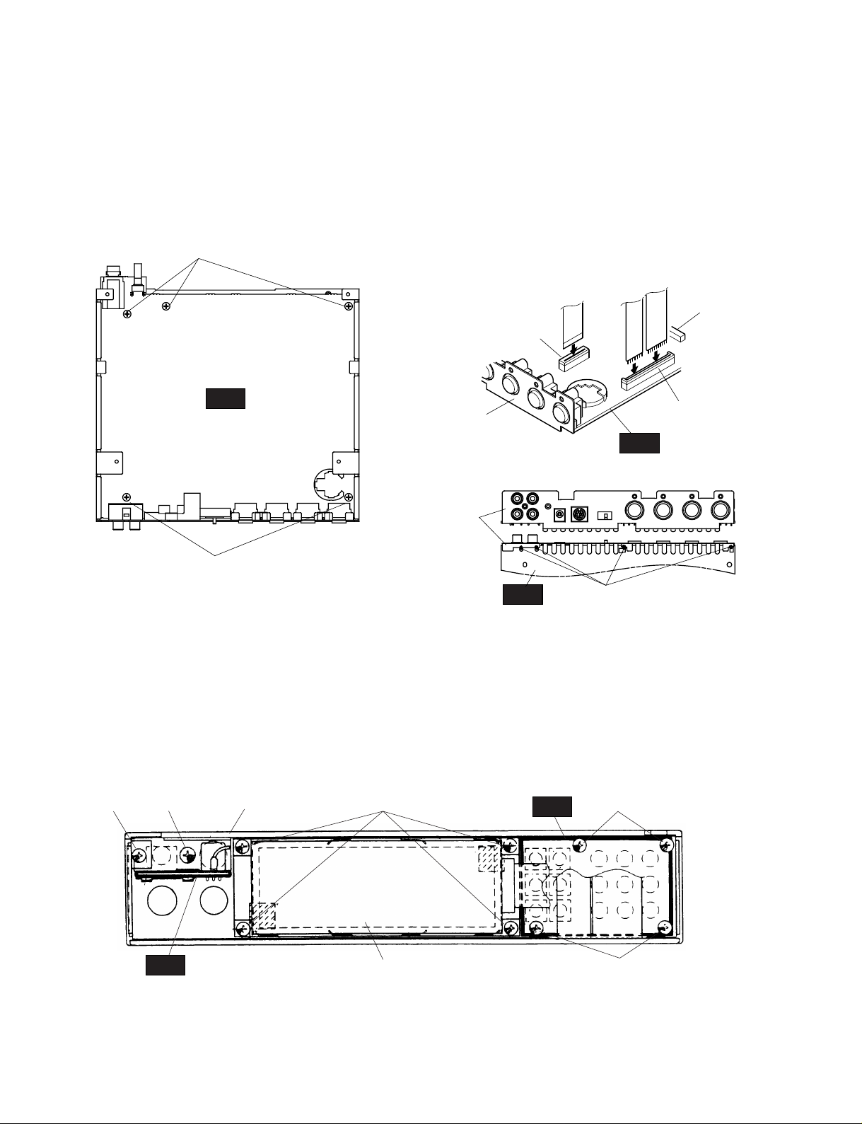
3. PSW & PVR circuit boards and LCD
[
F40
][
F30
] [
F90
]
[
F90
]
PVR
PSW
Front panel
LCD
[
F60
]
21
43
2
43
12
[F30]: Bind Head Tapping Screw-B 3.0X10 MFZN2Y (EP600220)
[F40]: Bind Head Tapping Screw-B 2.6X10 MFZN2Y (VD791000)
[F60]: Bind Head Tapping Screw-B 2.6X10 MFZN2Y (VD791000)
[F90]: Bind Head Tapping Screw-B 2.6X6 MFZN2Y (VC069600)
(Fig.5)
2-3 Remove the five (5) screws marked [T30]. The DM
circuit board can then be removed. (Fig. 3)
Pull off the A/D INPUT knob from the DM circuit
board.
Melt and remove the solder of the four (4) points
marked [A]. The rear shield can then be remove from
the DM circuit board. (Fig. 4-1,4-2)
* When you reattach the DM circuit board, you should
tighten the screws in the order described in figure 3.
The cables plugged into the connector CN9 should
be inserted as shown in figure 4-1.
[
T30
]
[
T30
]
[A]
DM
DM
DM
SW2
(7P)
Rear shield
Rear shield
SW1
(10P)
CN9
CN5
1
1
17
16
1
3
4
52
CN1
[T30]: Bind Head Tapping Screw-B 3.0X6 MFZN2BL (EP600230)
(Fig.4-1)
(Fig.4-2)
(Fig.3)
3-1 Remove the bottom assembly. (See Procedure 1.)
3-2 Remove the top assembly. (See Procedure 2.)
3-3 Remove the four (4) screws marked [F90]. The PSW
circuit board can then be removed. (Fig. 5)
Pull off the OP buttons and the mode buttons from
the PSW Circuit board.
3-4 Remove the screw marked [F30] and the screw
marked [F40]. The PVR circuit board can then be
removed. (Fig. 5)
3-5 Remove the four (4) screws marked [F60]. The LCD
can then be removed. (Fig. 5)
* When you reattach the circuit boards, you should
tighten the screws in the order described in figure 5.
MU100
9
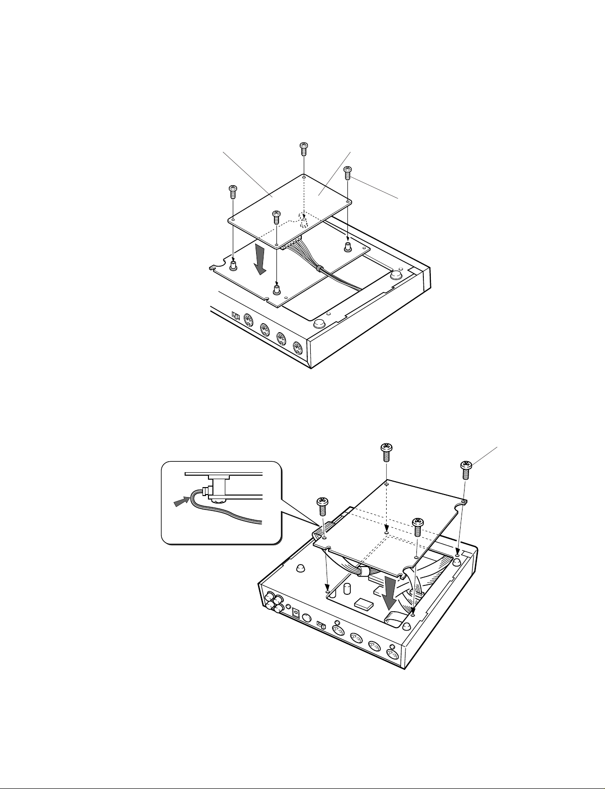
Installing a Plug-in Board into the MU100
Warning
Installation and removal of a plug-in board into/from the MU100 initializes some of the setup and multipart settings of the main unit. Be sure to save any of your important settings onto a personal computer or
MIDI Data Filer MDF3 before installing or removing a plug-in board.
CAUTION!
Be careful not to injure your hands or fingers while installing or removing the plug-in board.
Be careful not to injure yourself when handling the jagged surfaces or sharp areas of the plug-in board.
CAUTION!
Accidents can occur if the plug-in board is installed or removed while the AC adaptor is connected to a
power source. Be sure to unplug the AC adaptor of the MU100 before installing or removing the plug-in
board.
Instructions
1. Turn off the power of any devices that may be connected to the MU100 and remove the MU100’s AC adaptor from its
power source.
2. Turn the MU100 upside down.
Remove the DB cover by removing the four (4) silver screws that secure it to the MU100.

Holder
Insert the connector so
that the tabs on the right
and left sides lock.
Tab
Expansion connector
XG Plug-in Connector
XG Plug-in Board
MU100
10
3. Remove the four (4), black, XG Plug-in Board installation screws that are secured to the inside of the DB cover.
Unlatch and remove the holder that secures the connector. Extend the connector.
Keep the holder for use when the XG Plug-in Board is removed.
4. Remove the XG Plug-in Board from the anti-static bag.
5. Insert the expansion connector of the MU100 into the connector of the XG Plug-in Board.
Make sure to insert the connector so that it faces the proper direction and the right and left tabs of the expansion
connector lock into place (as shown in the illustration).
CAUTION!
Before handling the XG Plug-in Board, be sure to touch a grounded, metal surface in order to remove
any static electricity from your clothes or body. Do not touch any of the patterned surfaces of the board
or its connector.
MU100
11
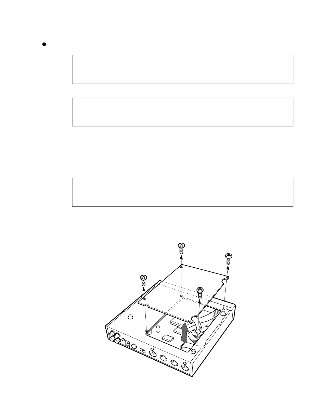
6. Attach the XG Plug-in Board to the DB cover using the four (4), black screws that were removed in Step 3.
Install the XG Plug-in Board so that the side with the IC chips is facing the DB cover.
Position the XG Plug-in Board from above, onto the DB cover, making sure to align the holes of the board with the
holes on the lid. If the holes are not properly aligned, you may damage the plug-in board.
Side without the connector
Screw (black)
XG Plug-in Board
7. Secure the DB cover back onto the MU100 by using the same four (4) silver screws that were removed in Step 2.
Secure the screws in the order shown in the illustration.
Arrange the cables of the
connector as shown, so
that they do not become
pinched or damaged.
Screw (silver)
1
2
3
4
LSI PIN DESCRIPTION
PIN
NO.
1
2
3
4
5
6
7
8
9
10
11
12
13
14
15
16
17
18
19
20
21
22
23
24
25
26
27
28
29
30
31
32
33
34
35
36
37
38
39
40
41
42
43
44
45
46
47
48
49
50
51
52
53
54
55
56
57
58
59
60
61
62
63
64
I/O
O
O
-
-
O
O
O
O
O
O
O
O
O
O
O
O
O
O
O
O
O
O
O
O
O
I
O
O
I
O
-
O
O
-
I/O
I/O
I/O
I/O
-
I/O
I/O
I/O
I/O
I/O
I/O
I/O
I/O
-
I/O
I/O
I/O
I/O
O
O
I
I
O
O
CS1
CS0
Vss
Vss
Vcc
A0
A1
A2
A3
Vss
A4
A5
A6
A7
A8
A9
A10
A11
Vss
A12
A13
A14
A15
A16
A17
A18
A19
Vss
A20
PA5
PA6
PA7
P67
P66
Vss
Vss
P65
P64
Vcc
D0
D1
D2
D3
Vss
D4
D5
D6
D7
D8
D9
D10
D11
Vss
D12
D13
D14
D15
Vcc
TXD0
TXD1
RXD0
RXD1
P34
P35
NAME
Chip Select for System RAM (CS1)
Chip Select for System RAM (CS0)
GND
Power Supply
Address Bus
GND
Address Bus
GND
Address Bus
GND
Address Bus
Off Line Detection
Signal for Rotary encoder(REB)
Signal for Rotary encoder(REA)
Plug Detection of A/D Input
NC
GND
GND
Reset Signal for SWP30
Reset Signal for PB
Power Supply
Two Way Data Bus
GND
Two Way Data Bus
GND
Two Way Data Bus
Power Supply
Serial MIDI OUT (TXD0)
Serial Host OUT (TXD1)
Serial MIDI IN B (RXD0)
Serial MIDI IN A (RXD1) or Host IN
A/D Gain Control Signal(ADG1)
A/D Gain Control Signal(ADG2)
FUNCTION
MU100
12
HD6432655A00F (XT443A00) CPU
PIN
NO.
65
66
67
68
69
70
71
72
73
74
75
76
77
78
79
80
81
82
83
84
85
86
87
88
89
90
91
92
93
94
95
96
97
98
99
100
101
102
103
104
105
106
107
108
109
110
111
112
113
114
115
116
117
118
119
120
121
122
123
124
125
126
127
128
I/O
-
O
-
O
O
O
O
O
O
O
O
O
O
O
O
I
I
I
-
-
O
O
O
O
O
O
O
O
I
-
O
O
I
I
I
I
I
I
I
I
I
I
-
-
I/O
I/O
I/O
I/O
I/O
I/O
I/O
I/O
I
I
I
O
O
O
Vss
P60
Vss
Vss
P61
P62
P63
P27
P26
P25
P24
P23
P22
P21
P20
WDT0VF
RES
NMI
STBV
Vcc
XTAL
EXTAL
Vss
Vcc
AS
RD
HWR
LWR
PF2
PF1
PF0
TXD2
RXD2
Vss
Vss
SCK2
P53
AVcc
Vref
AN0
AN1
AN2
AN3
AN4
AN5
AN6
AN7
AVss
Vss
P17
P16
P15
P14
P13
P12
P11
P10
MD0
MD1
MD2
PG0
CS3
CS2
NAME
GND
NC
GND
GND
NC
PB Select (SW1)
PB Select (SW2)
NC
1 MHz Clock for Serial Interface
LCD Contrast (LCDC-C)
LCD Contrast (LCDC-B)
LCD Contrast (LCDC-A)
LCD Control (LCD-E)
LCD Control (LCD-R/W)
LCD Control (LCD-RS)
NC
Reset Signal
not used
not used
Power Supply
Quartz Cristal 16 MHz
Quartz Cristal 16 MHz
GND
NC
Power Supply
NC
Read Signal
Write Signal
NC
PB Select (SW4)
SW Data Read Control (SWD)
LED,SW Strobe Data Latch (SWS)
Serial Output for PB (TXD2)
Serial Input for PB (RXD2)
GND
GND
Serial Sync Clock for PB (MIDCLK)
Reset Signal for Rotary Encoder
Power Supply for A/D
Reference Voltage for A/D
Analog Level Input R
not used
Analog Level Output L
not used
Detection of Host SW Position
not used
Battery Voltage Check
ModelCheck (MU100:GND)
GND
GND
LCD Data(DB7),SW Data,LED6
LCD Data(DB6),SW Strobe Data
LCD Data(DB5),SW Strobe Data
LCD Data(DB4),SW Data,LED5
LCD Data(DB3),SW Data,LED4
LCD Data(DB2),SW Data,LED3
LCD Data(DB1),SW Data,LED2
LCD Data(DB0),SW Data,LED1
GND
GND
+5 D
PB Select (SW3)
NC
Chip Select for SWP30 (CS2)
FUNCTION
 Loading...