


7P4-F8199-U0
EF4000DFW
EF4000FW
OWNER’S MANUAL
MANUEL D’UTILISATION
BEDIENUNGSANLEITUNG
MANUALE PER IL PROPRIETARIO
E
F
D
I
Read this manual carefully before operating this machine.
Il convient de lire attentivement ce manuel avant la première utilisation de la machine.
Bitte lesen Sie diese Bedienungsanleitung sorgfältig durch, bevor Sie die Maschine in Betrieb nehmen.
Leggere attentamente questo manuale prima di utilizzare questa macchina.

7P4-F8199-U0-E0
EF4000DFW
EF4000FW
OWNER’S MANUAL
Read this manual carefully before operating this machine.

Read this manual carefully before operating this machine. This manual should
stay with this machine if it is sold.

INTRODUCTION
Congratulations on your purchase of your new Yamaha.
This manual will provide you with a good basic understanding of the operation and
maintenance of this machine.
If you have any questions regarding the operation or maintenance of your machine,
please consult a Yamaha dealer.
EF4000DFW/EF4000FW
OWNER’S MANUAL
©2014 by Yamaha Motor Powered
Products Co., Ltd.
1st Edition, April 2014
All rights reserved.
Any reprinting or unauthorized use
without the written permission of
Yamaha Motor Powered
Products Co., Ltd.
is expressly prohibited.
Printed in China
Particularly important information is distinguished in this manual by the following
notations.
This is the safety alert symbol. It is
used to alert you to potential personal
injury hazards. Obey all safety messages that follow this symbol to avoid possible injury or death.
WARNING
A WARNING indicates a hazardous situation which, if not avoided, could
result in death or serious injury.
NOTICE
A NOTICE indicates special precautions that must be taken to avoid damage to the machine or other property.
TIP
A TIP provides key information to make
procedures easier or clearer.
WARNING
PLEASE READ AND UNDERSTAND
THIS MANUAL COMPLETELY BEFORE
OPERATING THE MACHINE.
TIP
9 Yamaha continually seeks advance-
ments in product design and quality.
Therefore, while this manual contains
the most current product information
available at the time of printing, there
may be minor discrepancies between
your machine and this manual. If
there is any question concerning this
manual, please consult a Yamaha
dealer.
9 This manual should be considered a
permanent part of this machine and
should remain with this machine
when resold.
* Product and specifications are subject to
change without notice.
IMPORTANT MANUAL INFORMATION

SAFETY INFORMATION ...................... 1
Exhaust fumes are poisonous ............ 2
Fuel is highly flammable and
poisonous ........................................... 2
Engine and muffler may be hot .......... 2
Electric shock prevention ................... 3
Connection notes ............................... 4
Connection ......................................... 4
Extension cord notes .......................... 4
LOCATION OF IMPORTANT
LABELS ................................................ 5
DESCRIPTION ...................................... 6
Control panel ...................................... 6
CONTROL FUNCTION ......................... 7
Engine switch ..................................... 7
Oil warning light (Red)........................ 7
AC switch (N.F.B.) .............................. 8
Fuel tank cap ...................................... 8
Fuel cock ............................................ 9
Ground (earth) terminal...................... 9
Choke lever ........................................ 9
Recoil starter .................................... 10
PREPARATION ................................... 11
Fuel .................................................. 11
Engine oil ......................................... 12
Ground (earth) terminal.................... 13
PRE-OPERATION CHECK ................. 14
Pre-operation check ......................... 14
OPERATION ....................................... 15
Starting the engine ........................... 15
Stopping the engine ......................... 17
Connection ....................................... 18
Application range ............................. 20
PERIODIC MAINTENANCE ................ 21
Maintenance chart ........................... 21
Carburetor adjustment ..................... 23
Spark plug inspection ....................... 23
Engine oil replacement ..................... 24
Air filter ............................................. 26
Muffler screen .................................. 27
Fuel cock .......................................... 28
Fuel tank filter ................................... 29
STORAGE ........................................... 30
Drain the fuel .................................... 30
Engine .............................................. 32
TROUBLESHOOTING ........................ 33
SPECIFICATIONS ............................... 35
Dimensions ...................................... 35
Engine .............................................. 35
Generator ......................................... 36
CONSUMER INFORMATION.............. 37
Identification number records ........... 37
Machine identification ....................... 37
WARRANTY ........................................ 38
WIRING DIAGRAM ............................. 39
EF4000DFW .................................... 39
EF4000FW ....................................... 40
CONTENTS
– 1 –
SAFETY INFORMATION
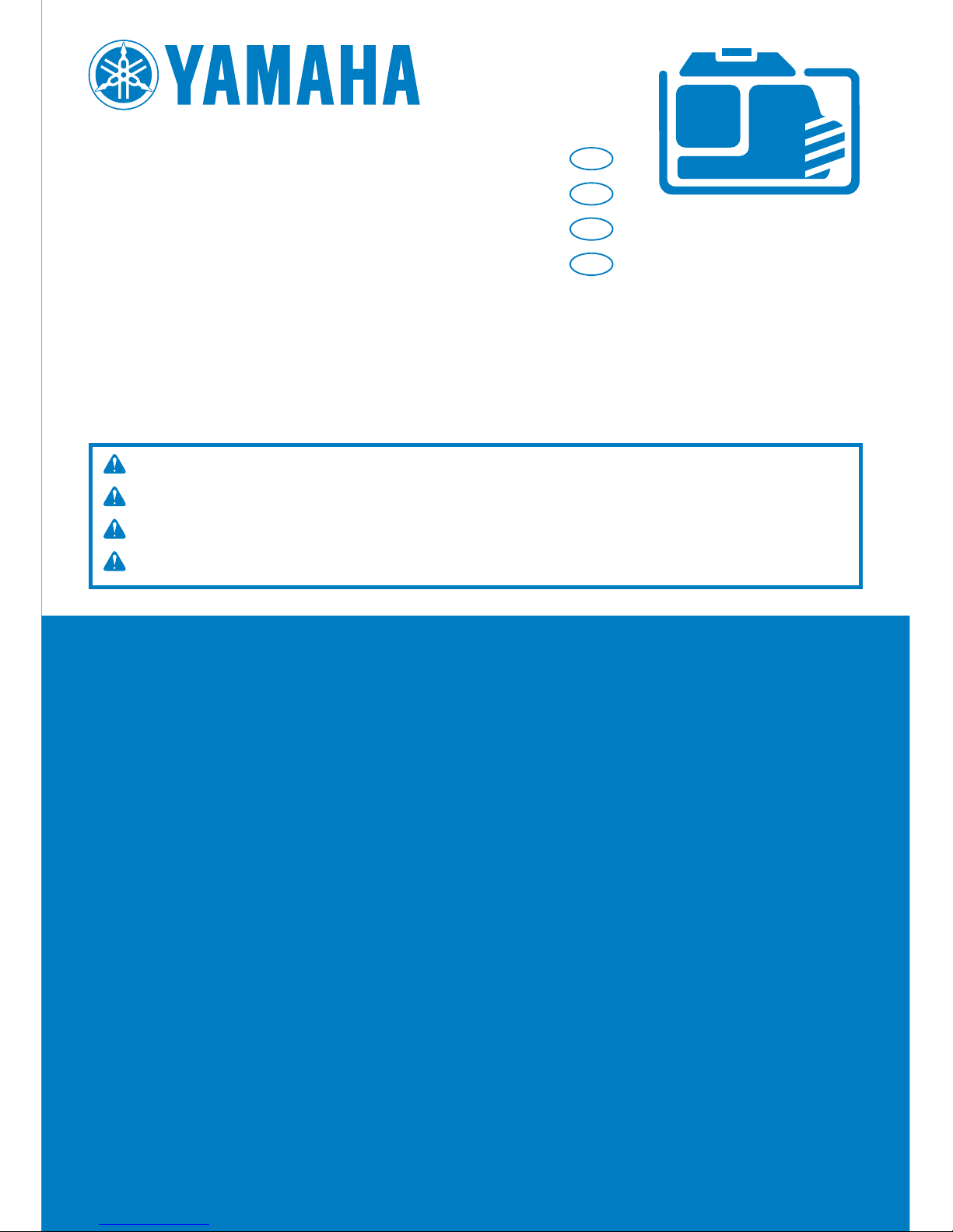
9 This generator is not designed for on-board use.
Do not use it while installed on the vehicle.
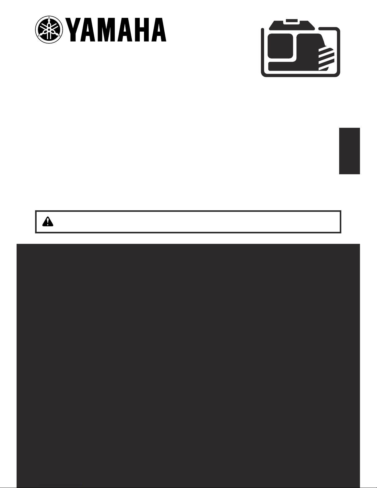
9 Do not modify the generator or use it with its parts
removed.
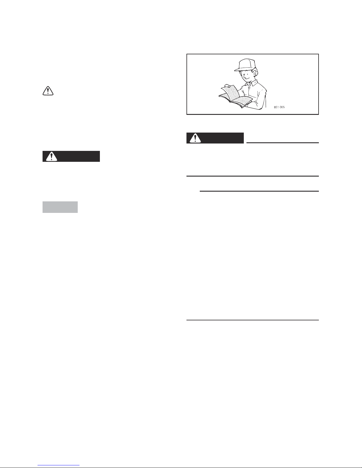
9 Do not allow children to operate the generator.
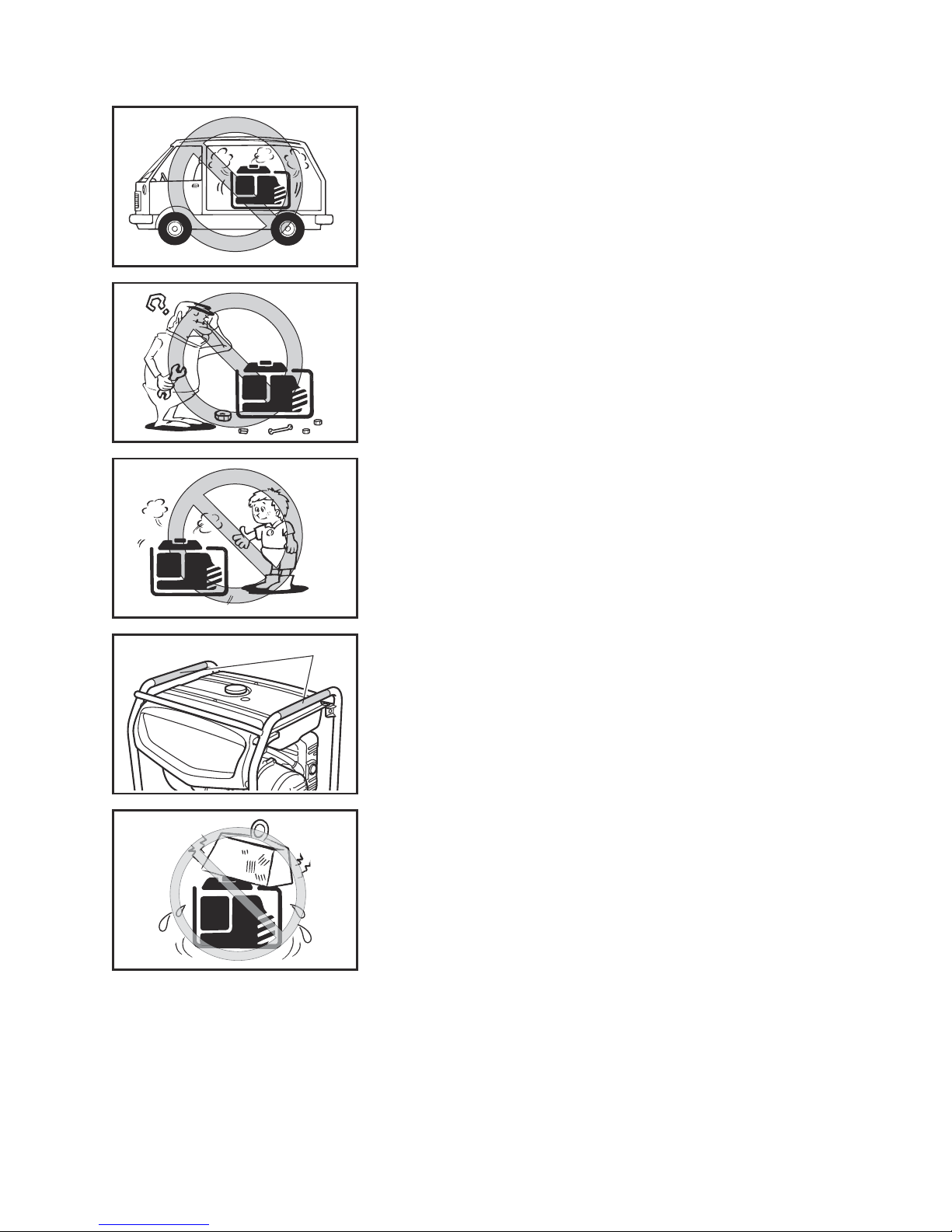
9 Be sure to carry the generator only by its carrying
handle(s).
1 Carrying handle(s) (shaded)
9 Do not place any obstacles on the generator.
1
– 2 –
741-003
741-005
741-004
741- 006
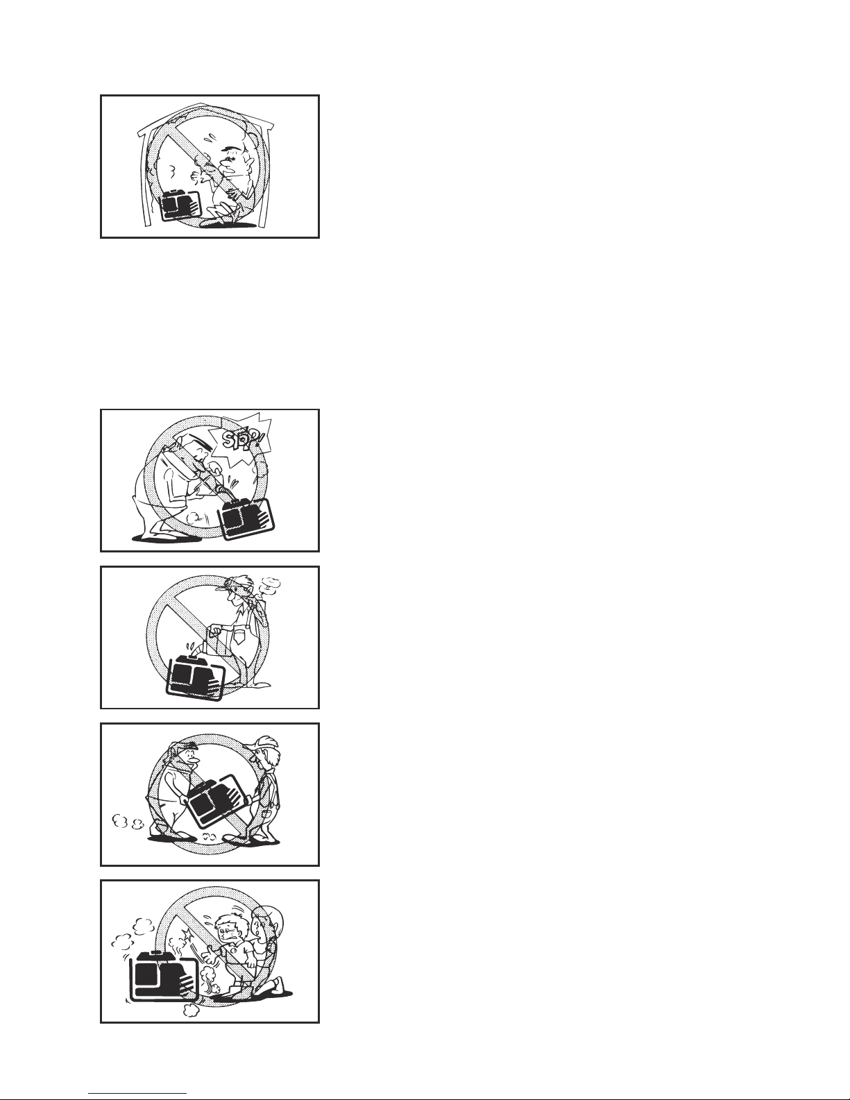
Fuel is highly flammable and poisonous
9 Always turn off the engine when refuelling.
9 Never refuel while smoking or in the vicinity of an
open flame.
9 Take care not to spill any fuel on the engine or
muffler when refuelling.
9 Do not leave the generator inside the vehicle or in
the trunk.
9 If you swallow any fuel, inhale fuel vapor, or allow
any to get in your eye(s), see your doctor immediately. If any fuel spills on your skin or clothing,
immediately wash with soap and water and
change your clothes.
9 When operating or transporting the generator, be
sure it is kept upright. If it tilts, fuel may leak from
the carburetor or fuel tank.
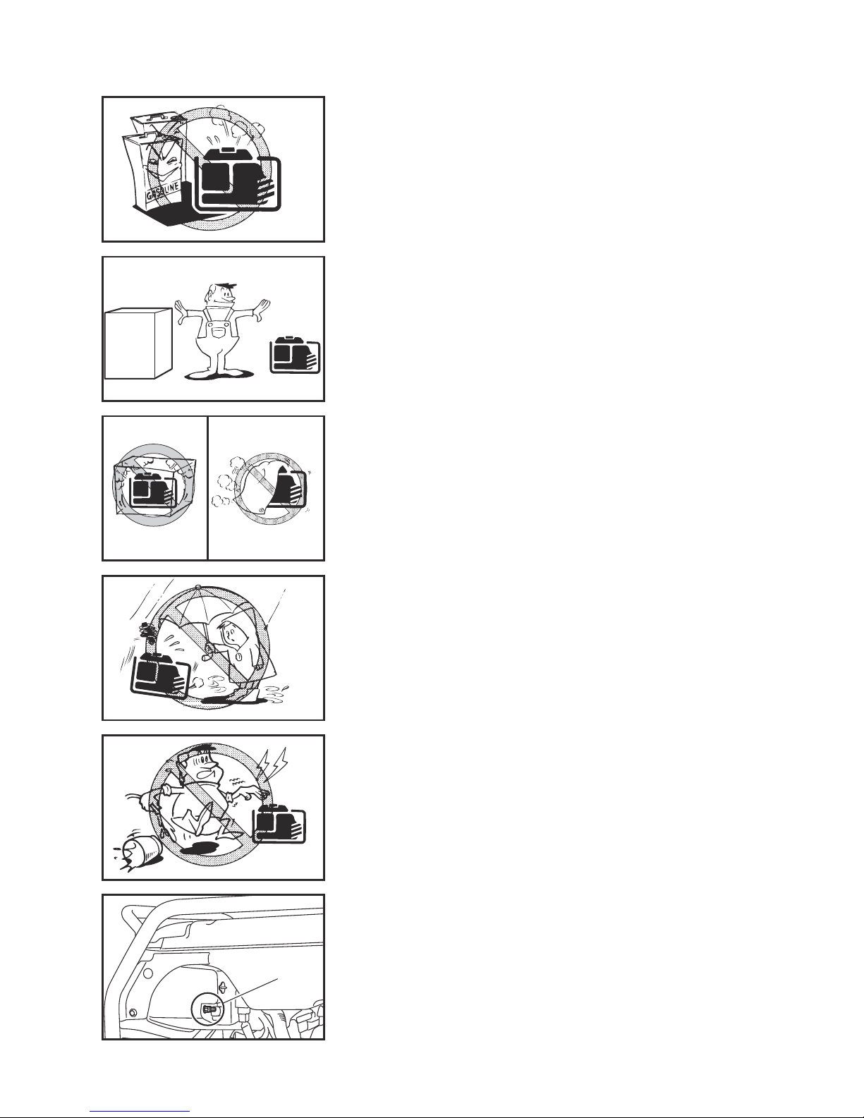
Engine and muffler may be hot
9 Place the generator in a place where pedestrians
or children are not likely to touch the generator.
741-002
Exhaust fumes are poisonous
9 Using a generator indoors CAN KILL YOU IN
MINUTES. Generator exhaust contains carbon
monoxide. This is a poison you cannot see or
smell.
9 NEVER use inside a home or garage, EVEN IF
doors and windows are open.
9 Only use OUTSIDE and far away from windows,
doors, and vents.
– 3 –
741-007
9 Avoid placing any flammable materials near the
exhaust outlet during operation.
741-008a
9 In order to prevent overheating, ensure adequate
airflow by keeping the machine at least 1 m (3 ft)
from objects or other equipment.
7CC-001
741-010
741-011
9 Do not operate the engine with a dust cover or
other objects covering it.
9 When covering the generator, be sure to do so
only after the engine and muffler have completely
cooled down.
Electric shock prevention
9 Never operate the engine in rain or snow.
9 Never touch the generator with wet hands or elec-
trical shock will occur.
9 Connect the ground (earth) terminal to a ground
source. In order to prevent electrical shock, the
generator must be grounded when using a
grounded electrical device.
1 Ground (earth) terminal
1
– 4 –
741-040a
1
2
1
2
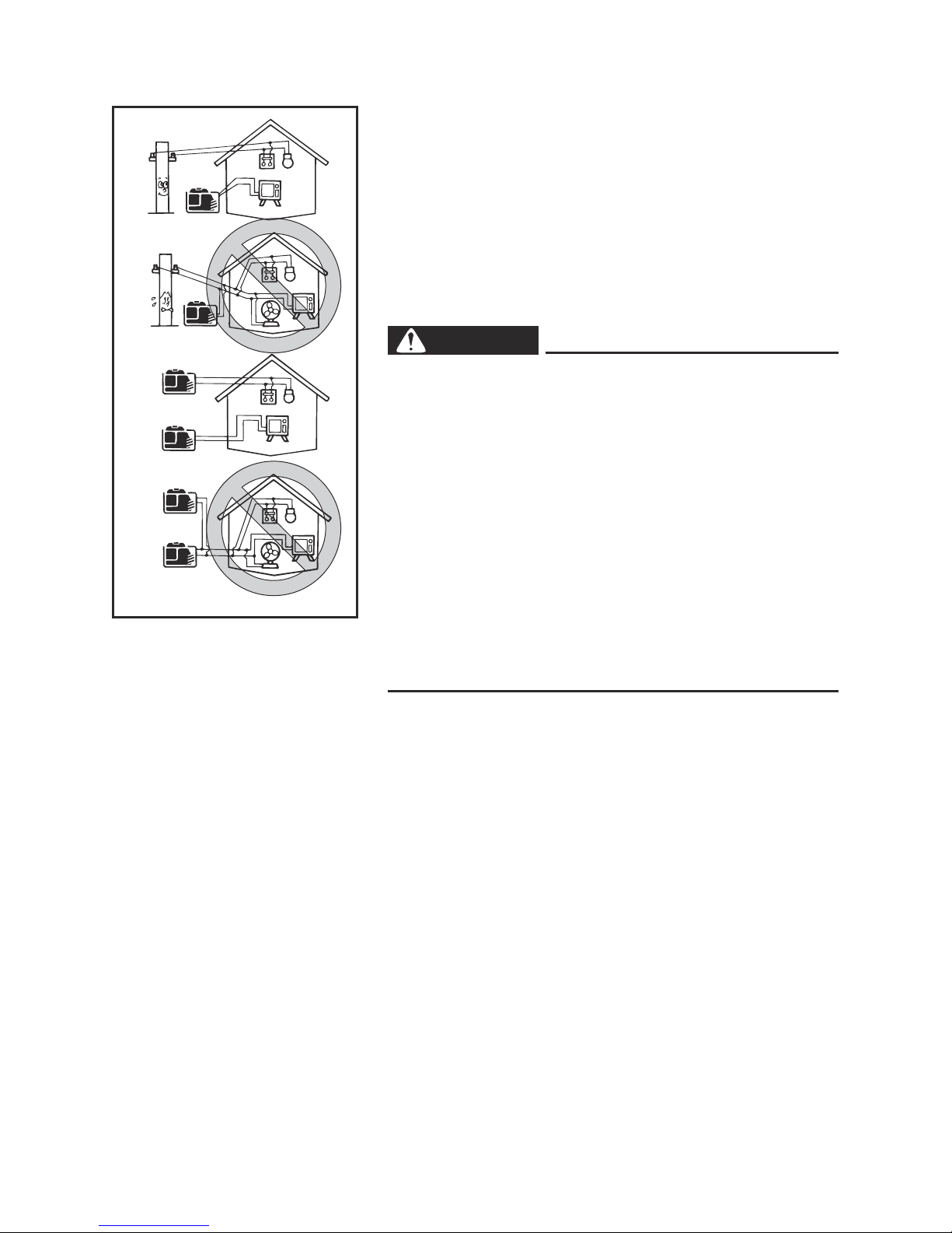
Connection notes
9 Avoid connecting the generator to commercial
power outlet.
9 Avoid connecting the generator in parallel with any
other generator.
1 Correct
2 Incorrect
Connection
WARNING
Before the generator can be connected to a building’s electrical system, a licensed electrician must
install an isolation (transfer) switch in the building’s main fuse box. The switch is the connection
point for generator power and allows selection of
generator or main line power to the building. This
will prevent the generator from charging the main
power line (backfeeding) when the main power
supply has failed or has been turned off for line
repair. Backfeeding can electrocute or injure line
maintenance personnel. Also, generator and building electrical system damage can occur when normal operating power returns if unit is used without
an isolation switch.
Extension cord notes
Extension cords should be protected by a tough flexible rubber sheath (IEC 245) or the equivalent to withstand mechanical stresses.
– 5 –
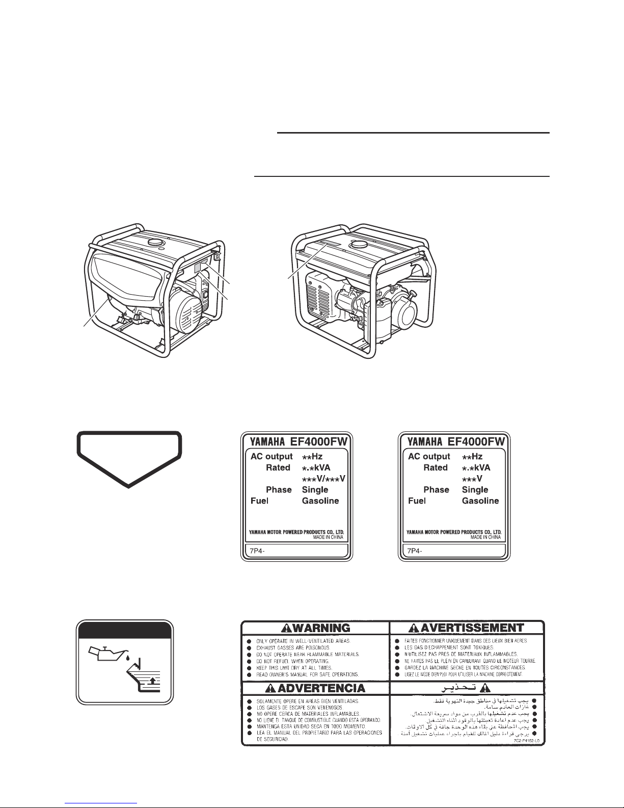
LOCATION OF IMPORTANT LABELS
Please read the following labels carefully before operating this generator.
TIP
Maintain or replace safety and instruction labels, as
necessary.
2 (For EF4000FW)
3
O I L
4
1
2
3
4
HOT EXHAUST
1 2 (For EF4000DFW)
– 6 –
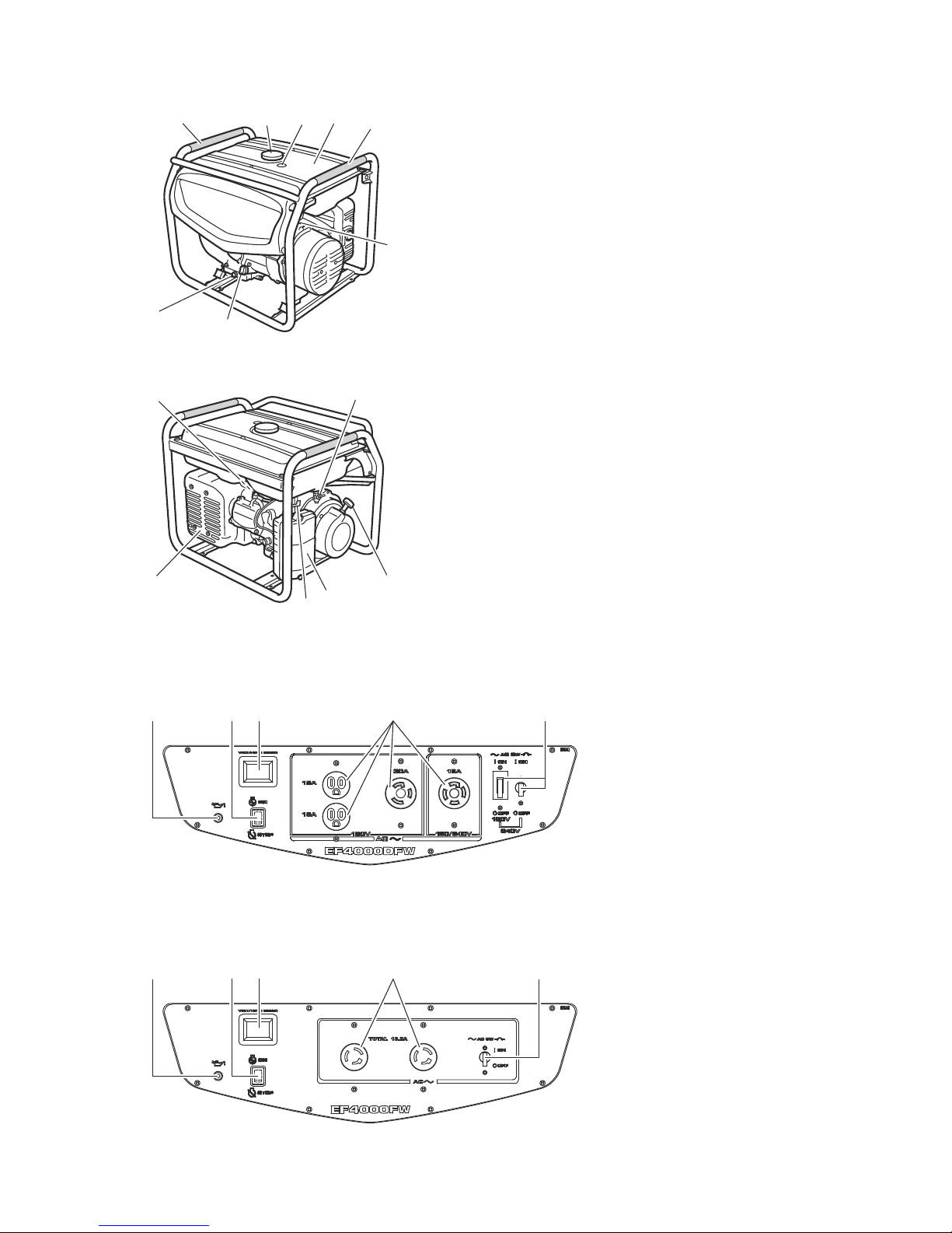
DESCRIPTION
1 Carrying handles (shaded)
2 Fuel tank cap
3 Fuel level gauge
4 Fuel tank
5 Ground (earth) terminal
6 Oil filler cap
7 Oil drain bolt
8 Spark plug
9 Fuel cock
0 Recoil starter
q Air filter case cover
w Choke lever
e Muffler
2
6
7
5
1
1
3
4
8
9
0
w
q
e
Control panel
1 Oil warning light (Red)
2 Engine switch
3 Voltage/hour meter
4 AC receptacle
5 AC switch (N.F.B.)
EF4000DFW
32 41 5
000-000
EF4000FW
32 41 5
000-000

– 7 –
CONTROL FUNCTION
Engine switch
The engine switch controls the ignition system.
1 “7” (ON)
Ignition circuit is switched on.
The engine can be started.
2 “5” (STOP)
Ignition circuit is switched off.
The engine will not run.
700-027c
Oil warning light (Red)
When the oil level falls below the lower level, the oil
warning light comes on and then the engine stops
automatically. Unless you refill with oil, the engine will
not start again.
TIP
If the engine stalls or does not start, turn the engine
switch to “7” (ON) and then pull the recoil starter. If the
oil warning light comes on, the engine oil is insufficient.
Add oil and restart.
1
2
– 8 –
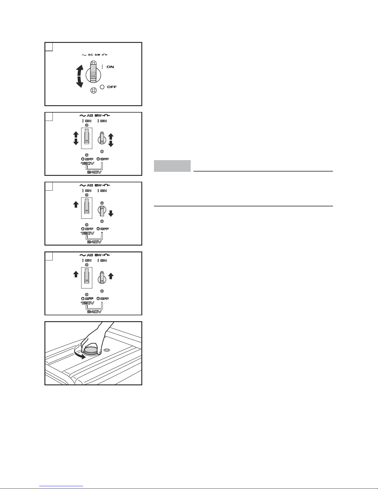
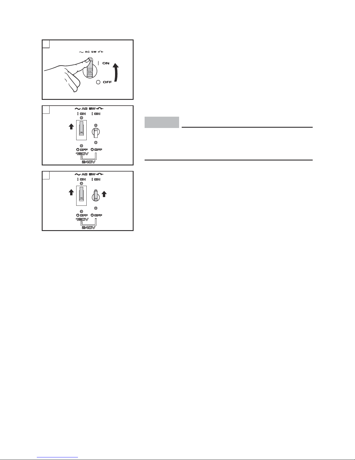
AC switch (N.F.B.)
The AC switch (Non-Fuse Breaker) turns off automatically when the load exceeds the generator rated output.
1 “I” (ON)
2 “3” (OFF)
å EF4000FW
∫ EF4000DFW
ç supplies AC 120 V (EF4000DFW)
∂ supplies AC 120 V and 240 V (EF4000DFW)
NOTICE
Reduce the load to the specified generator rated
output if the AC switch (N.F.B.) turns off. If it turns
off again, consult a Yamaha dealer.
1
2
763-252a
A
1
2
1
2
B
2
1
C
1
1
D
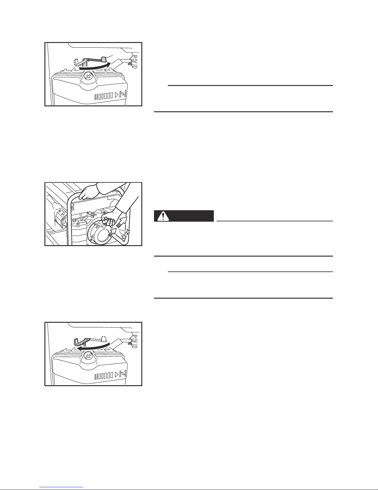
Fuel tank cap
Remove the fuel tank cap by turning it counterclockwise.
– 9 –
7DF-106
1
22
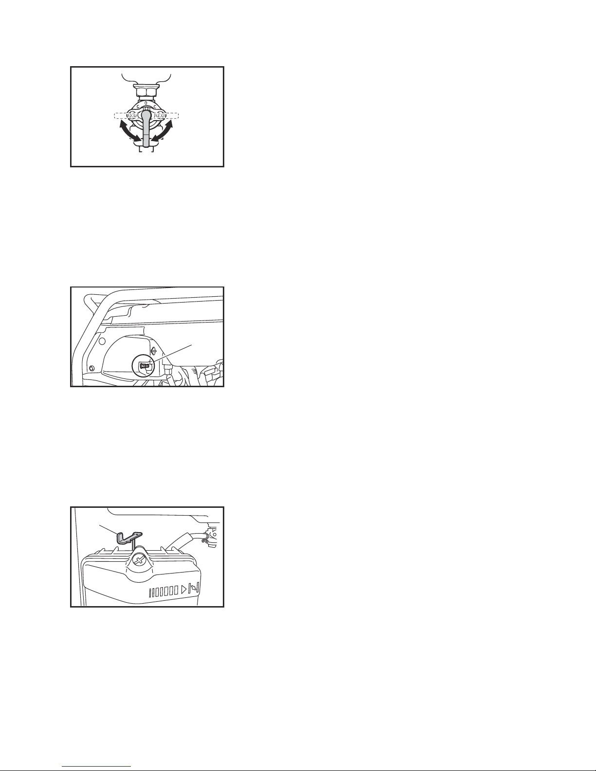
Fuel cock
The fuel cock supplies fuel from the fuel tank to the
carburetor.
The fuel cock has two positions.
1 ON
With the lever in this position, fuel flows to the carburetor. Normal using is done with the lever in this position.
2 OFF
With the lever in this position, fuel will not flow. Always
turn the lever to this position when the engine is not
running.
1
1
Choke lever
Starting a cold engine requires a richer air-fuel mixture, which is supplied by the choke lever.
1 Choke lever
Ground (earth) terminal
Make sure to ground (earth) the generator.
Check “SAFETY INFORMATION” (See page 3).
1 Ground (earth) terminal

– 10 –
Recoil starter
The recoil starter is used to start the engine.
Pull the recoil starter slowly until it is engaged, then
pull it briskly.
1 Recoil starter handle
NOTICE
9 Pull the recoil starter handle straight.
9 Return the recoil starter handle slowly.
9 Do not touch the recoil starter handle while the
generator is operating.
1

– 11 –
1 2
PREPARATION
Fuel
WARNING
9 Fuel is highly flammable and poisonous.
Check “SAFETY INFORMATION” (See page 2)
carefully before filling.
9 Do not overfill the fuel tank, otherwise it may
overflow when the fuel warms up and expands.
9 Wipe up any spilled fuel immediately.
9 After filling the tank with fuel, make sure the
fuel tank cap is tightened securely.
1. Stop the engine.
2. Place the generator on a level surface.
3. Remove the fuel tank cap.
4. Check the fuel level.
5. If low, fill the tank with fuel.
NOTICE
9 Immediately wipe off spilled fuel with a clean,
dry, soft cloth, since fuel may deteriorate paint-
ed surfaces or plastic parts.
9 Use only unleaded gasoline. The use of leaded
gasoline will cause severe damage to internal
engine parts.
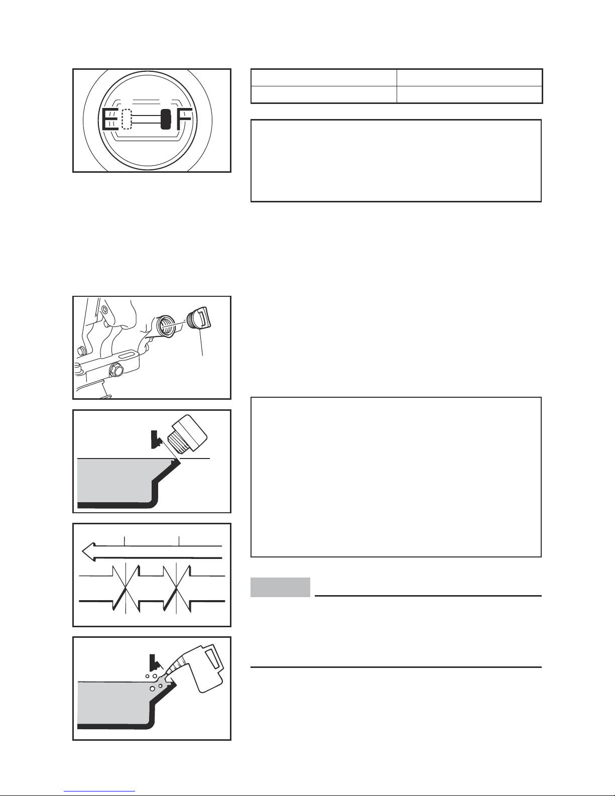
Make sure there is sufficient fuel in the tank.
When refueling, do not fill the tank up above the top
edge of the fuel tank filter.
1 Fuel level
2 Fuel tank filter
3 Fuel level gauge
3
– 12 –
4
“F” Full
5
“E” Empty
Recommended fuel:
Unleaded gasoline
Fuel tank capacity:
Total:
28 L (7.40 US gal, 6.16 Imp gal)
4
5
7DK-093
1
700-110a
2
0°C
A
YAMALUBE 4 (10W-40)
D
SAE 10W
C
SAE #20
B
SAE #30
32°F
25°C
80°F
700-006
Engine oil
Make sure the engine oil is at the correct level of the
oil filler hole.
1 Oil filler cap
2 Correct level
Recommended engine oil:
å YAMALUBE 4 (10W-40),
SAE 10W-30 or 10W-40
∫ SAE #30
ç SAE #20
∂ SAE 10W
Recommended engine oil grade:
API Service SE type or higher
Engine oil quantity:
1.1 L (1.16 US qt, 0.97 Imp qt)
NOTICE
The generator was shipped from the factory without engine oil. Do not start the engine for the first
time until the oil level has been checked and oil
added if necessary.

– 13 –
1
Ground (earth) terminal
Make sure to ground (earth) the generator.
Check “SAFETY INFORMATION” (See page 3).
1 Ground (earth) terminal

– 14 –
PRE-OPERATION CHECK
WARNING
If any item in the pre-operation check is not working properly, have it inspected and repaired before
operating the generator.
The condition of a generator is the owner’s responsibility. Vital components can start to deteriorate quickly
and unexpectedly, even if the generator is unused.
TIP
Pre-operation checks should be made each time the
generator is used.
Pre-operation check
Fuel (See page 11)
9 Check fuel level in fuel tank.
9 Refuel if necessary.
Fuel line
9 Check fuel hose for cracks or damage.
9 Replace if necessary.
Engine oil (See page 12)
9 Check oil level in engine.
9 If necessary, add recommended oil to specified
level.
9 Check generator for oil leakage.
The point where abnormality was recognized by
use
9 Check operation.
9 If necessary, consult a Yamaha dealer.
– 15 –
OPERATION
WARNING
9 Never operate the engine in a closed area or it
may cause unconsciousness and death within
a short time. Operate the engine in a well ven-
tilated area.
9 Before starting the engine, do not connect any
electric devices.
9 Clean dusts, dirt or water off the receptacle
before use.
NOTICE
The generator was shipped from the factory without engine oil. Do not start the engine for the first
time until the oil level has been checked and oil
added if necessary.
Starting the engine
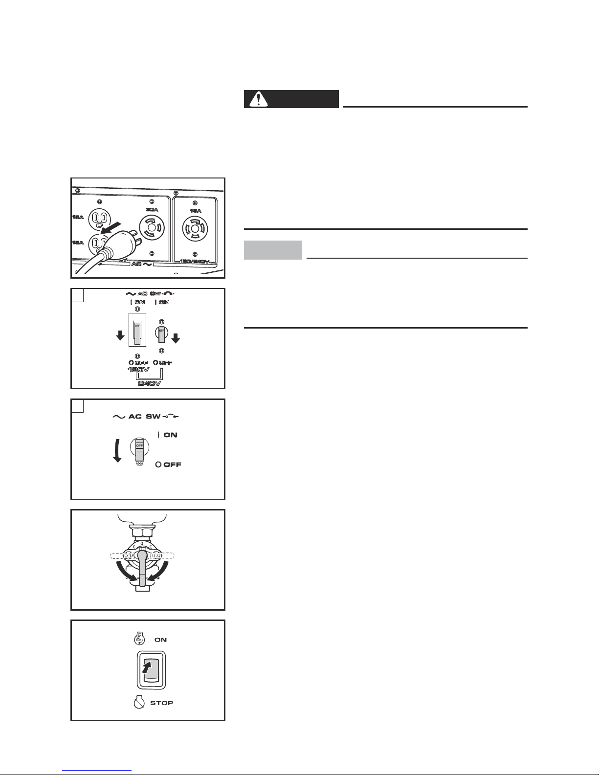
1. Turn the AC switch (N.F.B.) to “3” (OFF).
1 “3” (OFF)
å AC switch (N.F.B.) (EF4000DFW)
∫ AC switch (N.F.B.) (EF4000FW)
705-037
2
2. Turn the fuel cock lever to ON.
2 ON
1
1
A
763-252b
1
B
3. Turn the engine switch to “7” (ON).
3 “7” (ON)
3
– 16 –
4. Turn the choke lever to “1”.
4 Choke lever
TIP
The choke is not required to start a warm engine. Turn
the choke lever to the original position.
4
5. Pull the recoil starter slowly until it is engaged,
then pull it briskly.
WARNING
Be careful to use the recoil starter. In rare cases,
the recoil starter handle can be drawn back quickly
by the engine kickback.
TIP
Grasp the carrying handle firmly to prevent the generator from falling over when pulling the recoil starter.
5
6. After the engine starts, warm up the engine until
the engine does not stop when the choke lever is
returned to the original position.
5 Original position
– 17 –
Stopping the engine
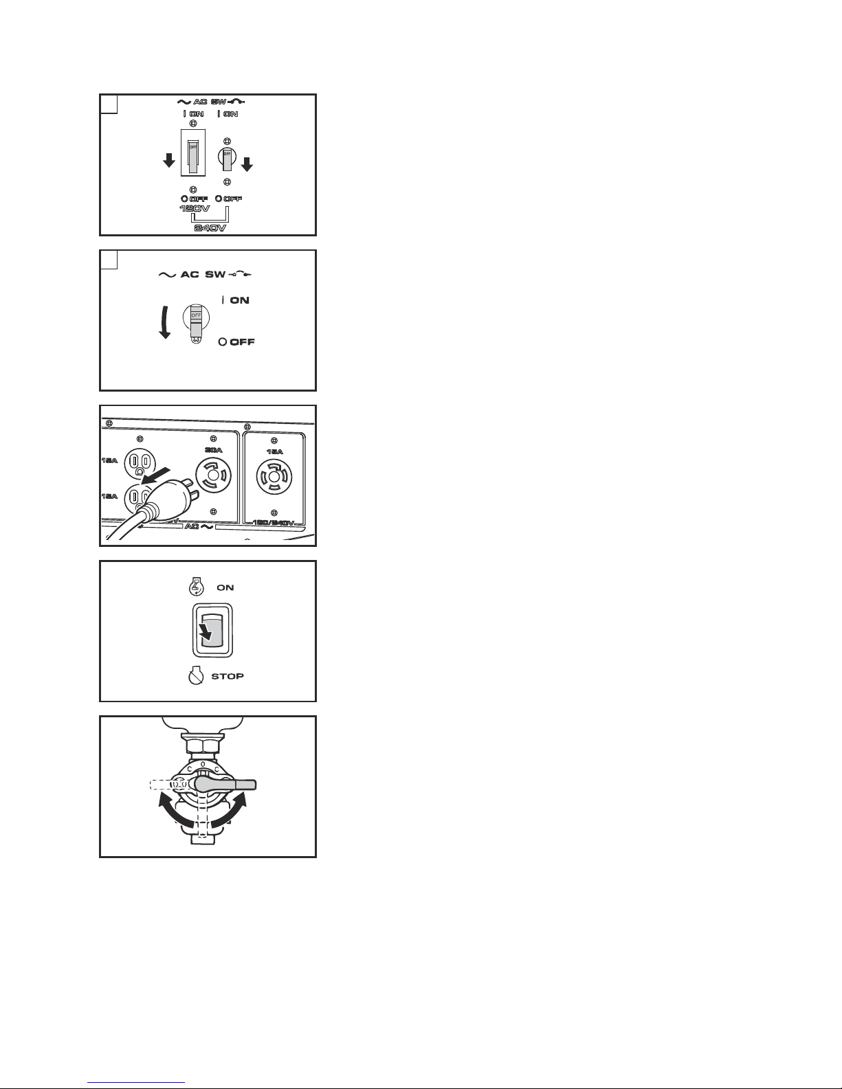
1. Turn off any electric devices.
2. Turn the AC switch (N.F.B.) to “3” (OFF).
1 “3” (OFF)
å AC switch (N.F.B.) (EF4000DFW)
∫ AC switch (N.F.B.) (EF4000FW)
3. Disconnect any electric devices.
1
1
A
763-252b
1
B
705-038d
33
4. Turn the engine switch to “5” (STOP).
2 “5” (STOP)
5. Turn the fuel cock lever to OFF.
3 OFF
2
– 18 –
1 2
000-000
Connection
Alternating current (AC)
WARNING
Be sure any electric devices are turned off before
plugging them in.
NOTICE
9 Be sure all electric devices including the lines
and plug connections are in good condition
before connection to the generator.
9 Be sure the total load is within generator rated
output.
9 Be sure the receptacle load current is within
receptacle rated current.
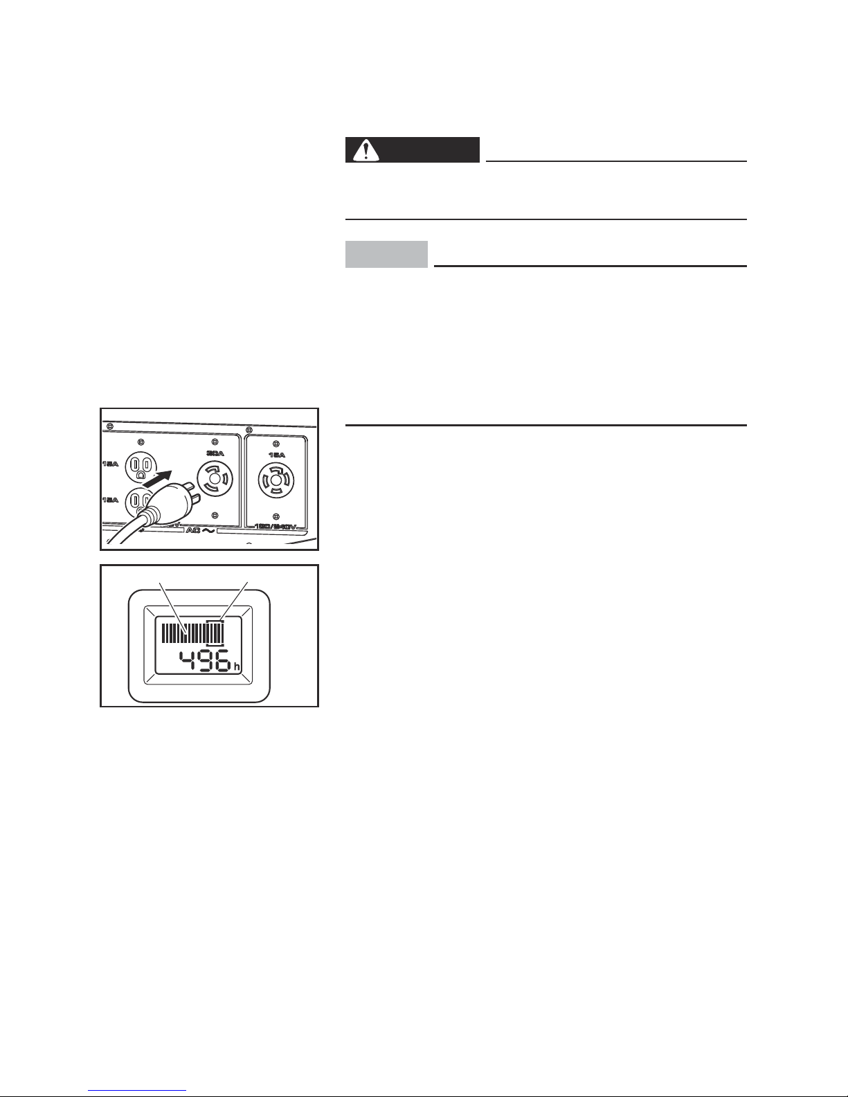
1. Start the engine.
2. Plug into AC receptacle.
3. Make sure the voltage/hour meter indicates the
rated voltage.
1 Voltage/hour meter
2 Rated voltage
– 19 –
3
763-252
A
3
3
C
4. Turn the AC switch (N.F.B.) to “I” (ON) and turn on
any electric devices.
3 “I” (ON)
å EF4000FW
∫ AC 120 V can be used. (EF4000DFW)
ç AC 120 V and 240 V can be used. (EF4000DFW)
NOTICE
Reduce the load to the specified generator rated
output if the AC switch (N.F.B.) turns off. If it turns
off again, consult a Yamaha dealer.
3
B
– 20 –
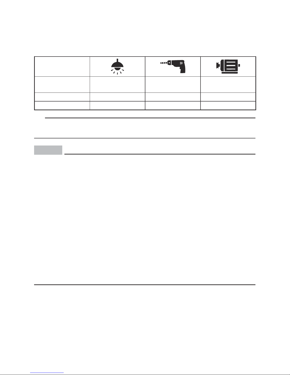
Application range
When using the generator, make sure the total load is within rated output of a generator.
Otherwise, generator damage may occur.
AC
Power factor 1 0.8–0.95
0.4–0.75
(Efficiency 0.85)
EF4000DFW –3500 W –2800 W –1190 W
EF4000FW –2900 W –2320 W –985 W
TIP
9 “–” means below.
9 Application wattage indicates when each device is used by itself.
NOTICE
9 Do not overload. The total load of all electrical appliances must not exceed the
supply range of the generator. Overloading will damage the generator.
9 Some types of precision equipment such as electronic controllers, PCs, elec-
tronic computers, microcomputer-based equipment and battery chargers are
sensitive to voltage fluctuations and may require more stable voltage supply
than the voltage supplied from the portable generator.
When using such equipment, consult with a Yamaha dealer.
9 When supplying precision equipment, electronic controllers, PCs, electronic
computers, microcomputer-based equipment or battery chargers, keep the
generator a sufficient distance away to prevent electrical interference from the
engine. Also ensure that electrical noise from the engine does not interfere
with any other electrical devices located near the generator.
9 If the generator is to supply medical equipment, advice should first be
obtained from the manufacturer, a medical professional or hospital.
9 Some electrical appliances or general-purpose electric motors have high
starting currents, and cannot therefore be used, even if they lie within the
supply ranges given in the above table. Consult the equipment manufacturer
for further advice.
– 21 –
PERIODIC MAINTENANCE
Safety is an obligation of the owner. Periodic inspection, adjustment and lubrication will
keep your generator in the safest and most efficient condition possible. The most important points of generator inspection, adjustment, and lubrication are explained on the following pages.
WARNING
If you are not familiar with maintenance work, have a Yamaha dealer do it for you.
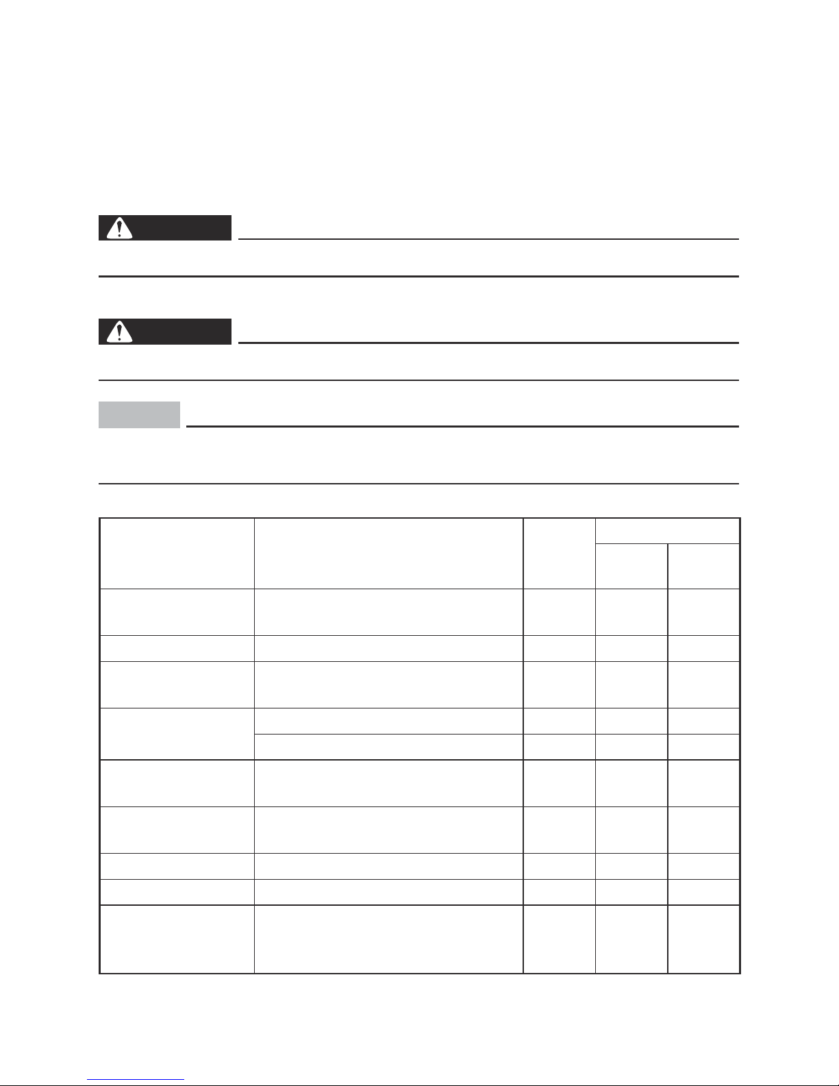
Maintenance chart
WARNING
Stop the engine before starting maintenance work.
NOTICE
Use only Yamaha specified genuine parts for replacement. Ask an authorized
Yamaha dealer for further attention.
Item Routine
Pre-
operation
check
Every
6 months
or 100 Hr
12 months
or 300 Hr
Spark plug
• Check condition.
• Clean and replace if necessary.
1
Fuel • Check fuel level and leakage.
1
Fuel hose
• Check fuel hose for cracks or damage.
• Replace if necessary.
1
Engine oil
• Check oil level in engine.
1
• Replace.
1(*1)
Air filter element
• Check condition.
• Clean.
1(*2)
Muffler screen
• Check condition.
• Clean and replace if necessary.
1
Fuel tank filter • Clean and replace if necessary.
1
Fuel strainer • Clean and replace if necessary.
1
Crankcase breather
hose
• Check breather hose for cracks or
damage.
• Replace if necessary.
1
– 22 –
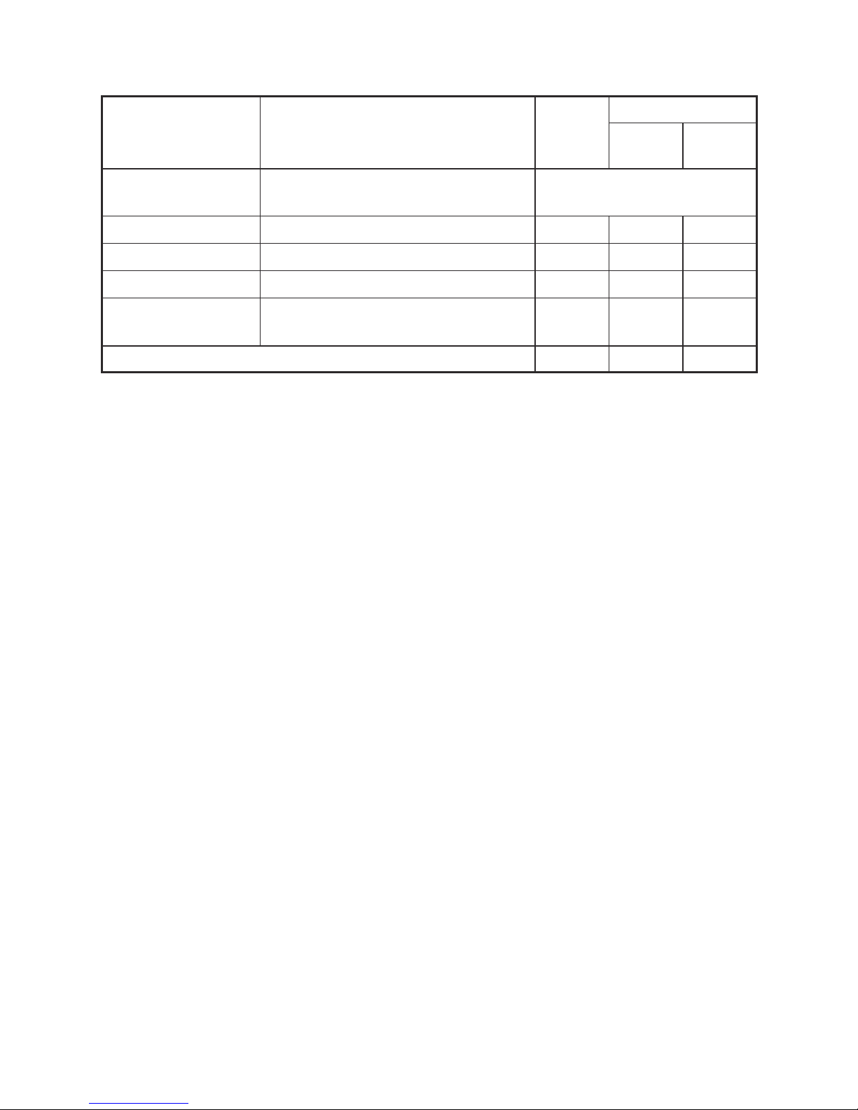
Item Routine
Pre-
operation
check
Every
6 months
or 100 Hr
12 months
or 300 Hr
Cylinder head
• Decarbonize cylinder head.
• More frequently if necessary.
After every 500 Hrs.
Valve clearance • Check and adjust valve clearance.
Idle speed • Check and adjust idle speed.
Recoil starter • Check recoil starter for damage.
Fittings/fasteners
• Check all fittings and fasteners.
• Correct if necessary.
The point where abnormality was recognized by use.
1
*1····· Initial replacement of the engine oil is after one month or 20 hours of operation.
*2····· The air filter element needs to be cleaned more frequently when using in unusually wet or
dusty areas.
····· Since these items require special tools, data and technical skills, have a Yamaha dealer perform the service.
– 23 –
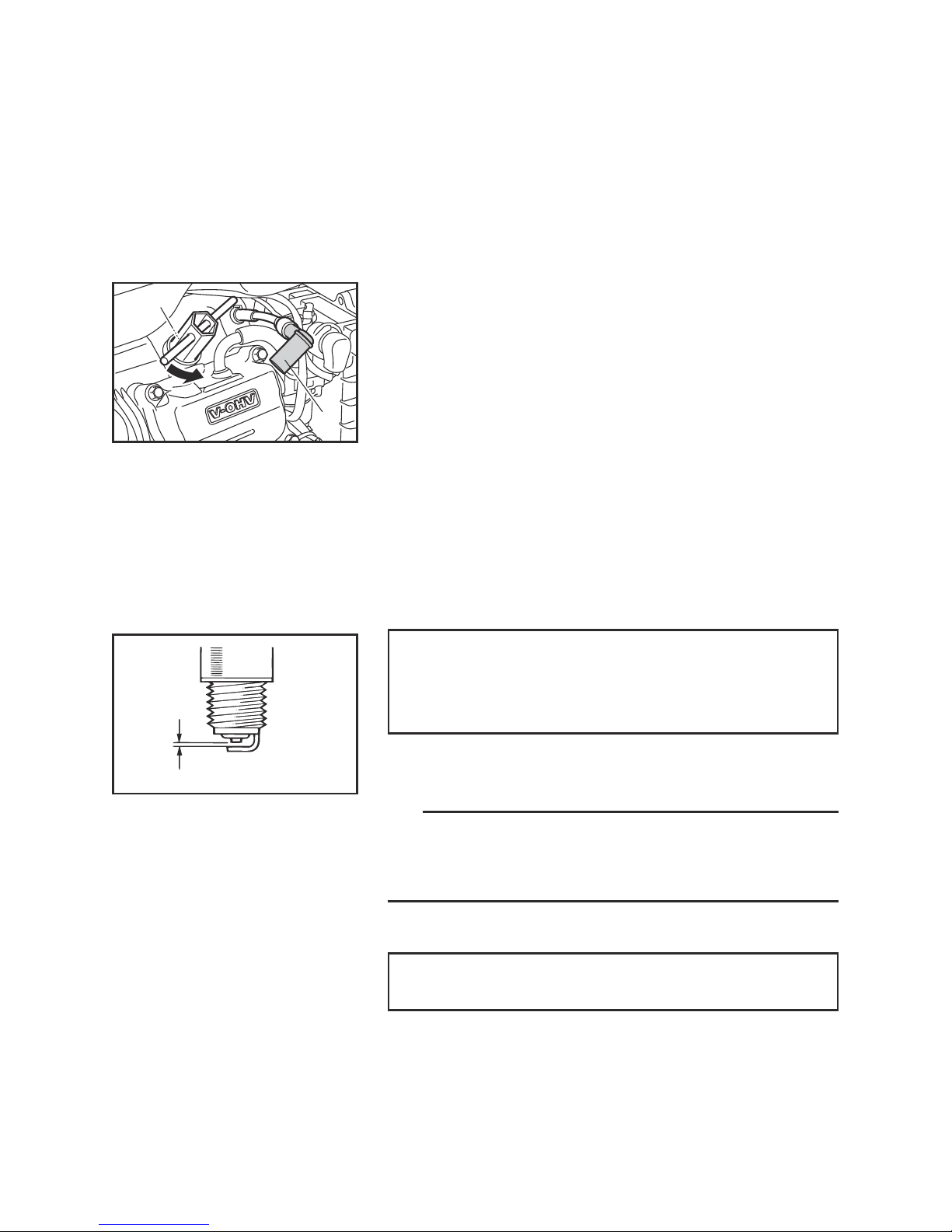
1
2
a
760-001a
Spark plug inspection
The spark plug is important engine components, which
should be checked periodically.
1. Remove the spark plug cap and the spark plug.
1 Spark plug cap
2 Spark plug
2. Check for discoloration and remove the carbon.
The porcelain insulator around the center elec-
trode of spark plug should be a medium-to-light
tan color.
3. Check the spark plug type and gap.
Standard spark plug:
BPR4ES (NGK)
Spark plug gap:
0.7–0.8 mm (0.028–0.031 in)
a Spark plug gap
TIP
The spark plug gap should be measured with a wire
thickness gauge and, if necessary, adjusted to specification.
4. Install the spark plug.
Spark plug tightening torque:
20 Nm (2.0 m·kgf, 14 ft·lbf)
Carburetor adjustment
The carburetor is a vital part of the engine. Adjusting
should be left to a Yamaha dealer with the professional
knowledge, specialized data, and equipment to do so
properly.