


OWNER’S MANUAL
Read this manual carefully before operating this machine.
Generator
EF3000iS
EF3000iSE
EF3000iSEB
LIT-19626-01-71
7CH-28199-15
Read this manual carefully before operating this machine. This manual
should stay with this machine if it is sold.

INTRODUCTION
790-066c
7CH-24163-**
Congratulations on your purchase of your new Yamaha.
This manual will provide you with a good basic understanding of the operation and maintenance of this machine.
If you have any questions regarding the operation or maintenance of your machine,
please consult a Yamaha dealer.
PRI-I.D. NUMBER
MODEL
PRI-I.D.
CODE
SERIAL No.
IDENTIFICATION NUMBER RECORDS
Record your Primary I.D., and serial numbers in the spaces provided, to assist you
in ordering spare parts from a Yamaha
dealer.
Also record and keep these I.D. numbers in
a separate place in case your machine is
stolen.
MACHINE IDENTIFICATION
The machine serial number is stamped in
the location as shown.
TIP
The first three digits of these numbers are
for model identification; the remaining digits are the unit production number. Keep a
record of these numbers for reference
when ordering parts from a Yamaha dealer.
EF3000iS
EF3000iSE
EF3000iSEB
OWNER’S MANUAL
© 2011 by Yamaha Motor Corporation, U.S.A.
1st Edition, October 2011
All rights reserved.
Any reprinting or unauthorized use
without the written permission of
Yamaha Motor Corporation, U.S.A.
is expressly prohibited.
Printed in Japan.
P/N LIT-19626-01-71

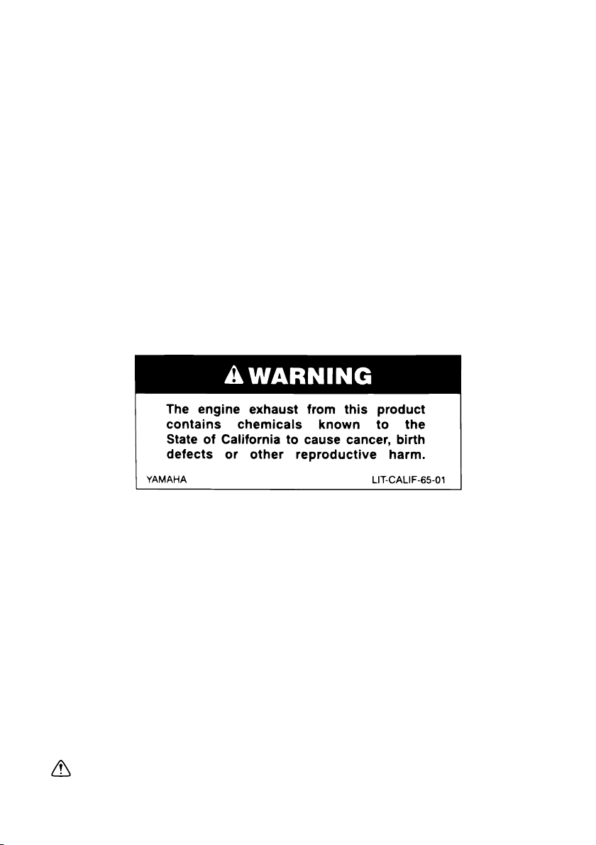
Par ticularly important information is distin-
NOTICE
WARNING
WARNING
guished in this manual by the following
notations.
This is the safety alert symbol. It is
used to alert you to potential personal
injury hazards. Obey all safety messages that follow this symbol to avoid
possible injury or death.
A WARNING indicates a hazardous situation which, if not avoided, could result
in death or serious injury.
A NOTICE indicates special precautions that must be taken to avoid damage to the machine or other property.
TIP
A TIP provides key information to make
procedures easier or clearer.
PLEASE READ AND UNDERSTAND
THIS MANUAL COMPLETELY BEFORE
OPERATING THE MACHINE.
TIP
9 Yamaha continually seeks advance-
ments in product design and quality.
Therefore, while this manual contains
the most current product information
available at the time of printing, there
may be minor discrepancies between
your engine and this manual. If there is
any question concerning this manual,
please consult a Yamaha dealer.
9 This manual should be considered a
permanent part of this engine and
should remain with this engine when
resold.
* Product and specifications are subject to
change without notice.

CONTENTS
LOCATION OF IMPORTANT
LABELS ..................................................1
SAFETY INFORMATION ........................3
EXHAUST FUMES ARE
POISONOUS .......................................3
FUEL IS HIGHLY FLAMMABLE AND
POISONOUS .......................................4
ENGINE AND MUFFLER MAY
BE HOT................................................4
ELECTRIC SHOCK PREVENTION.....5
CONNECTION NOTES .......................6
CONNECTION.....................................6
EXTENSION CORD NOTES ...............6
DESCRIPTION........................................7
CONTROL PANEL ...............................8
ENGINE SWITCH................................9
OIL WARNING LIGHT (red).................9
ECONOMY CONTROL SWITCH ......10
DC PROTECTOR ..............................10
FUEL COCK KNOB ...........................11
CASTER LOCK LEVER.....................11
PRE-OPERATION CHECK...................12
FUEL..................................................12
ENGINE OIL ......................................13
GROUND (earth) TERMINAL ............13
BATTERY ...........................................14
OPERATION .........................................16
STARTING THE ENGINE ..................16
APPLICATION RANGE......................19
CONNECTION...................................20
STOPPING THE ENGINE..................25
PERIODIC MAINTENANCE .................26
MAINTENANCE CHART ...................26
SPARK PLUG INSPECTION .............28
CARBURETOR ADJUSTMENT.........29
ENGINE OIL REPLACEMENT ..........29
MUFFLER SCREEN AND SPARK
ARRESTER .......................................31
AIR FILTER ........................................32
FUEL TANK FILTER...........................34
BATTERY ...........................................35
RECOMMENDED BATTERY.............35
FUSE REPLACEMENT .....................36
TROUBLESHOOTING..........................37
STORAGE.............................................39
DRAIN THE FUEL .............................39
ENGINE .............................................40
BATTERY ...........................................41
EXHAUST EMISSION CONTROL
SYSTEM AND COMPONENTS............42
SPECIFICATIONS.................................43
DIMENSIONS ....................................43
ENGINE .............................................43
GENERATOR.....................................43
WIRING DIAGRAM...............................44
EF3000iS ...........................................44
EF3000iSE.........................................45
EF3000iSEB ......................................46

YAMAHA MOTOR CORPORATION,
U.S.A.
EF SERIES GENERATORS
3-YEAR LIMITED WARRANTY............47
WARRANTY QUESTIONS AND
ANSWERS ............................................49
YAMAHA OUTDOOR POWER
EQUIPMENT
CALIFORNIA EVAPORATIVE
EMISSION CONTROL
WARRANTY STATEMENT ...................50
YAMAHA MOTOR CORPORATION,
U.S.A.
SMALL OFF ROAD ENGINES
CALIFORNIA EMISSION
CONTROL WARRANTY .......................51
YAMAHA EXTENDED SERVICE
(Y.E.S.) ..................................................55
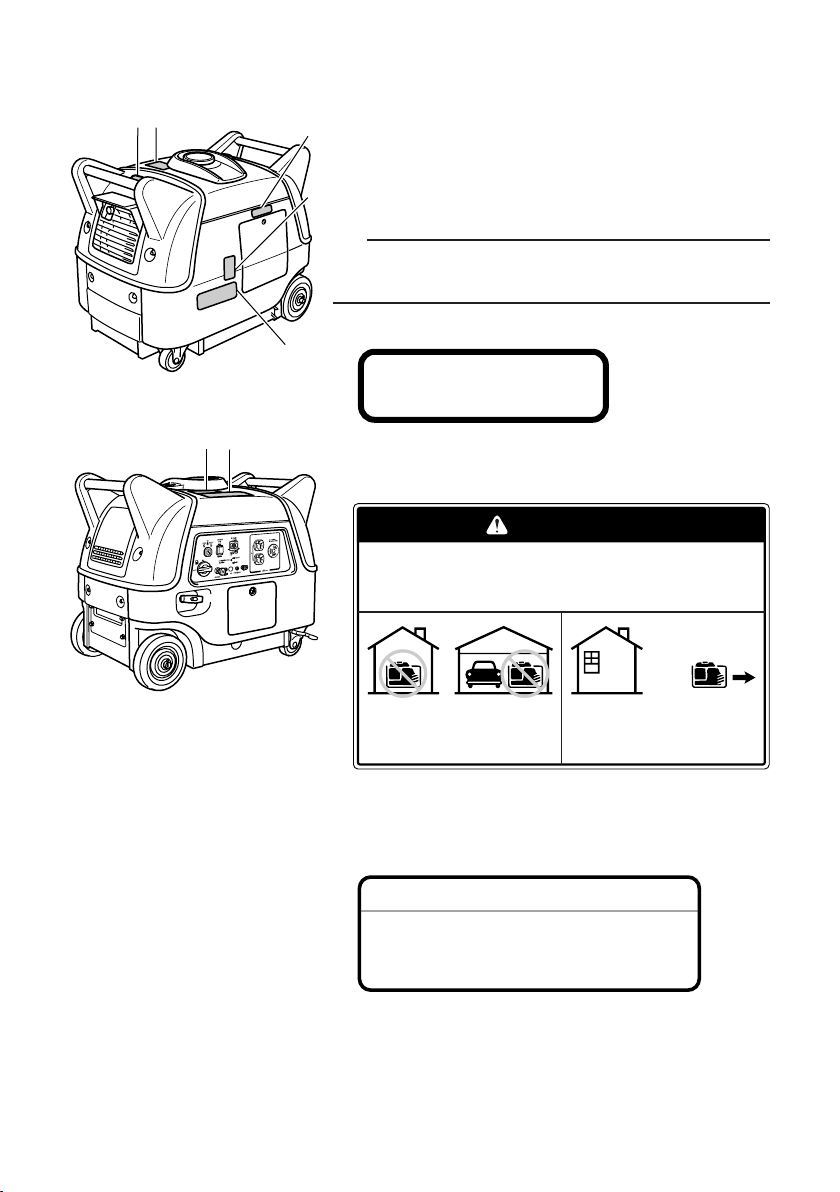
LOCATION OF IMPORTANT LABELS
1 2
3
5
4
67
DANGER
Using a generator indoors CAN KILL YOU IN MINUTES.
Generator exhaust contains carbon monoxide.
This is a poison you cannot see or smell.
NEVER use inside a home
or garage, EVEN IF doors
and windows are open.
Only use OUTSIDE and
far away from windows,
door, and vents.
HOT EXHAUST
7WL-28176-10
NOTICE
Use the specified spark plug only.
Specified plug:BPR4ES(NGK)
Please read the following labels carefully before operating this generator.
TIP
Maintain or replace safety and instruction labels, as
necessary.
1
2
3
– 1 –
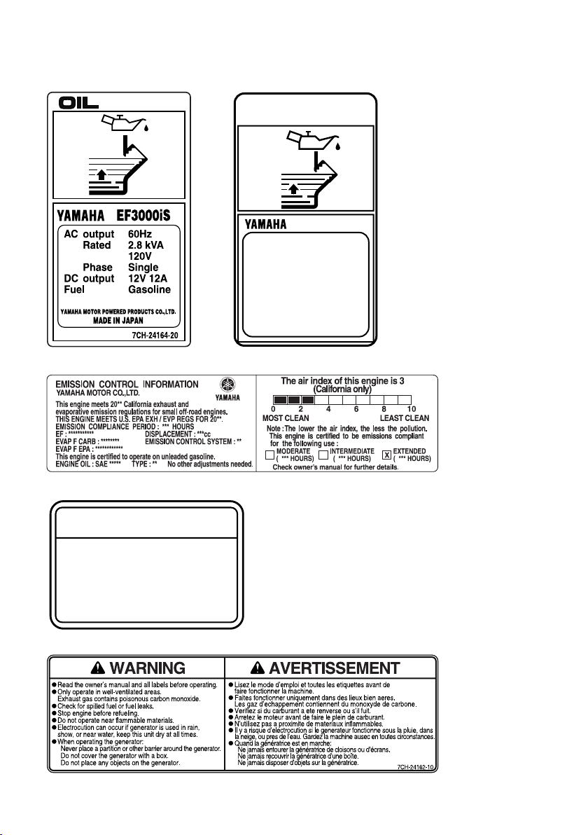
WARNING
Electrocution or property damage
can occur: Do not connect this
generator to any building ’s electrical
system unless an isolation switch
has been installed by a licensed electrician. Refer to the owner’s manual.
q
7XF-2415A-10
4
OIL
EF3000iSE(B)
AC output 60Hz
Rated 2.8kVA
Phase Single
DC output 12V 12A
Fuel
Gasoline
YAMAHA MOTOR POWERED PRODUCTS CO.,LTD.
MADE IN JAPAN
120V
7WL-24164-21
EF3000iS EF3000iSE, EF3000iSEB
4
5
6
7
– 2 –

741-092
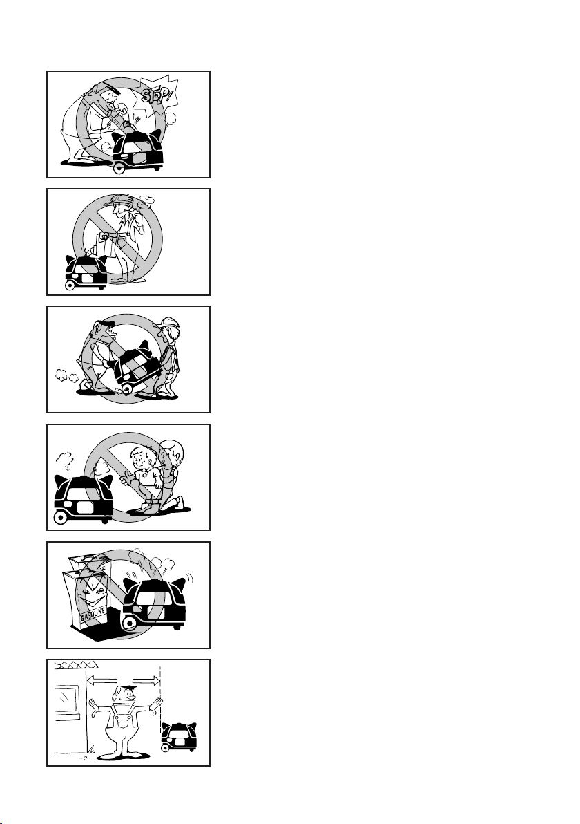
SAFETY INFORMATION
1
741-100
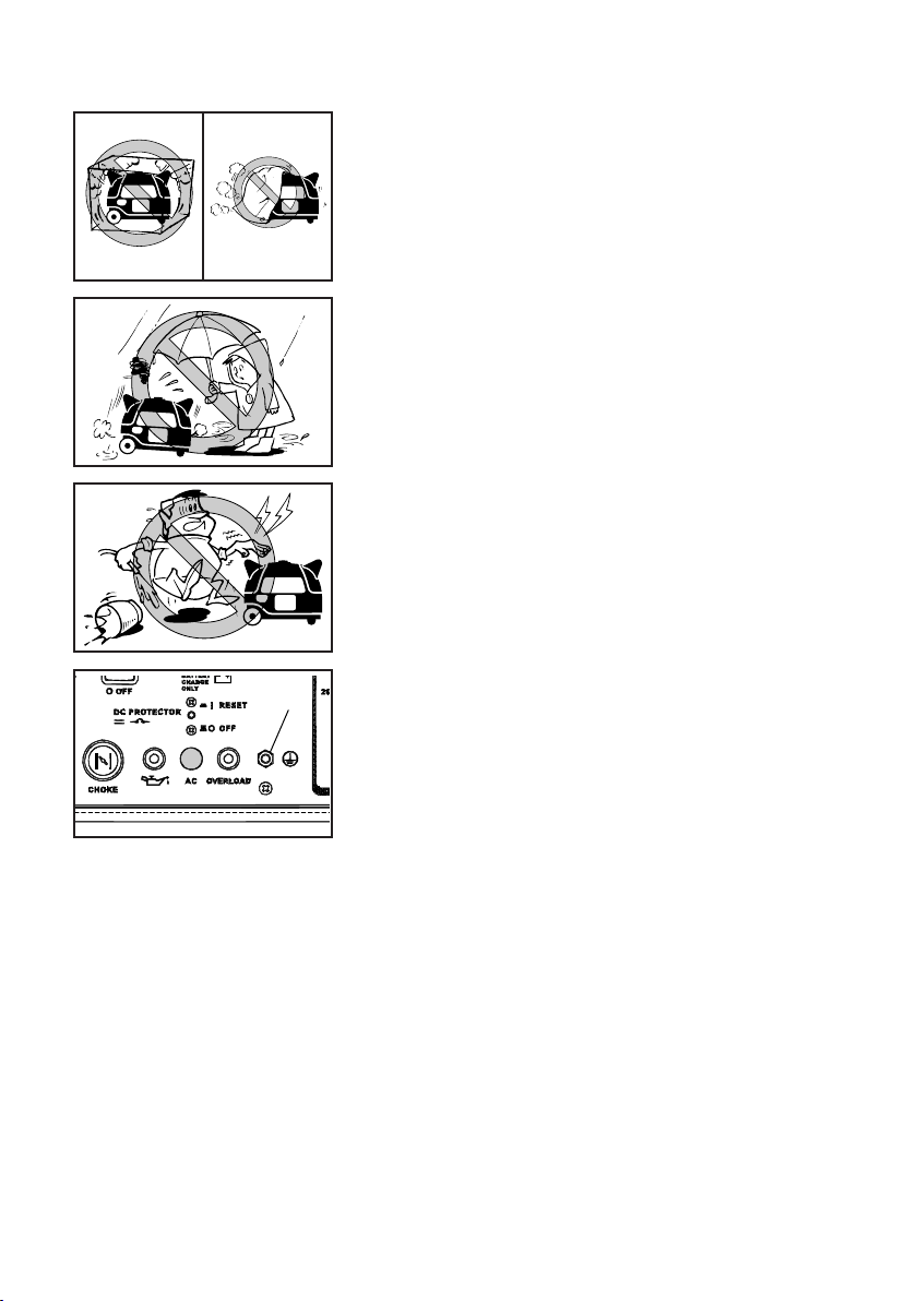
9 This generator is not designed for on-board use.
Do not use it while installed on the vehicle.
9 Do not modify the generator or use it with its parts
removed.
9 Do not allow children to operate the generator.
9 Be sure to carry the generator only by its carrying
handle(s).
1 Carrying handle(s) (shaded)
9 Do not place any obstacles on the generator.
7CH-002
EXHAUST FUMES ARE POISONOUS
9 Never operate the engine in a closed area or it may
cause unconsciousness and death within a short
time. Operate the engine in a well ventilated area.
– 3 –
741-098
a
741-096
741-095a
FUEL IS HIGHLY FLAMMABLE AND POISONOUS
9 Always turn off the engine when refuelling.
9 Never refuel while smoking or in the vicinity of an
open flame.
741-093
741-094
9 Ta ke care not to spill any fuel on the engine or muf-
fler when refuelling.
9 Do not leave the generator inside the vehicle or in
the trunk.
9 If you swallow any fuel, inhale fuel vapor, or allow
any to get in your eye(s), see your doctor immediately. If any fuel spills on your skin or clothing,
immediately wash with soap and water and change
your clothes.
9 When operating or transporting the generator, be
sure it is kept upright. If it tilts, fuel may leak from
the carburetor or fuel tank.
ENGINE AND MUFFLER MAY BE HOT
9 Place the generator in a place where pedestrians
or children are not likely to touch the generator.
9 Avoid placing any flammable materials near the
exhaust outlet during operation.
741-097
9 Keep the generator at least 1 m (3 ft) from buildings
or other equipment, or the engine may overheat.
a 1 m (3 ft)
– 4 –
741-102
741-101
9 Do not operate the engine with a dust cover or
1
other objects covering it.
9 When covering the generator, be sure to do so only
741-099
after the engine and muffler have completely
cooled down.
ELECTRIC SHOCK PREVENTION
9 Never operate the engine in rain or snow.
9 Never touch the generator with wet hands or elec-
trical shock will occur.
9 Connect the ground lead of the generator to the
ground (earth) terminal and connect the end to the
ground electrode buried in the ground.
1 Ground (earth) terminal
– 5 –

1
2
1
2
741-104
CONNECTION NOTES
WARNING
9 Avoid connecting the generator to commercial
power outlet.
9 Avoid connecting the generator in parallel with any
other generator.
1 Correct
2 Incorrect
CONNECTION
Before the generator can be connected to a building’s electrical system, a licensed electrician must
install an isolation (transfer) switch in the building’s main fuse box. The switch is the connection
point for generator power and allows selection of
generator or main line power to the building. This
will prevent the generator from charging the main
power line (backfeeding) when the main power supply has failed or has been turned off for line repair.
Backfeeding can electrocute or injure line maintenance personnel. Also, generator and building
electrical system damage can occur when normal
operating power returns if unit is used without an
isolation switch.
EXTENSION CORD NOTES
Extension cords should be protected by a tough flexible
rubber sheath (IEC 245) or the equivalent to withstand
mechanical stresses.
– 6 –

DESCRIPTION
4
2
3
1
793-107c
6
67
793-108c
5
1 Recoil starter
2 Oil filler cap
3 Oil drain bolt
4 Battery box/Battery
(For EF3000iSE, EF3000iSEB)
5 Muffler
6 Carrying handles (shaded)
7 Fuel tank cap
– 7 –

1
23
4
q
0
9
87
5
6
1
23
4
q
0
9
87
5
6
EF3000iS
EF3000iSE, EF3000iSEB
CONTROL PANEL
1 Engine switch
2 Economy control switch
3 DC receptacle
4 AC receptacle
5 Ground (earth) terminal
6 Overload indicator light
7 AC pilot light
8 DC protector
9 Oil warning light
0 Choke knob
q Fuel cock knob
– 8 –

1
2
763-119
1
2
3
A
ENGINE SWITCH
The engine switch controls the ignition system.
1 7 “ON”
Ignition circuit is switched on.
The engine runs on its position.
B
2 5 “STOP”
Ignition circuit is switched off.
The engine will not run.
3 6 “START”
Starting circuit is switched on.
The starter motor starts and the engine can be started.
Ta ke your hand off the switch immediately after the
engine starts.
A EF3000iS
B EF3000iSE, EF3000iSEB
OIL WARNING LIGHT (red)
When the oil level falls below the lower level, the oil
warning light comes on and then the engine stops automatically. Unless you refill with oil, the engine will not
start again.
TIP
If the engine stalls or does not start, turn the engine
switch to “START” or pull the recoil starter. If the oil
warning light comes on, the engine oil is insufficient.
Add oil and restart.
700-121
– 9 –
1
2
763-124a
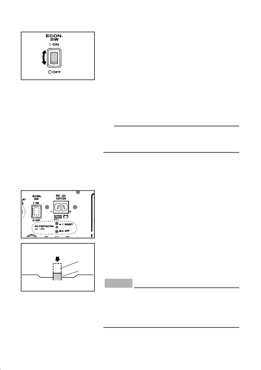
ECONOMY CONTROL SWITCH
763-231
NOTICE
1 I “ON”
When the economy control switch is turned to “ON”,
the economy control unit controls the engine speed
according to the connected load. The results are better
fuel consumption and less noise.
2 3 “OFF”
When the economy control switch is turned to “OFF”,
the engine runs at the rated r/min (3,800 r/min) regardless of whether there is a load connected or not.
TIP
The economy control switch must be turned to “OFF”
when using electric devices that require a large starting
current, such as a compressor or a submersible pump.
DC PROTECTOR
The DC protector turns off automatically when electric
device being connected to the generator is operating
and current above the rated flows. To use this equipment again, turn on the DC protector by pressing its
button to “RESET”.
1 “RESET”
Direct current is output. (This is the default position.)
2
1
763-238a
2 “OFF”
Direct current is not output.
Reduce the load of the connected electric device
below the specified rated output of the generator if
the DC protector turns “OFF”. If the DC protector
turns “OFF” again, stop using the device immediately and consult a Yamaha dealer.
– 10 –

q1
w2
FUEL COCK KNOB
712-029c
q1
w2
The fuel cock supplies fuel from the fuel tank to the carburetor. The fuel cock has two positions.
1 “ON”
With the knob in this position, fuel flows to the carburetor.
Normal using is done with the knob in this position.
2 “OFF”
With the knob in this position, fuel will not flow. Always
turn the knob to this position when the engine is not
running.
CASTER LOCK LEVER
The caster lock lever stops moving the generator.
1 “RELEASE”
2 “LOCK”
– 11 –
741-105
PRE-OPERATION CHECK
WARNING
WARNING
Pre-operation checks should be made each time the
generator is used.
The engine and the muffler will be very hot after the
engine has been run.
Avoid touching the engine and the muffler while
they are still hot with any part of your body or clothing during inspection or repair.
707-100
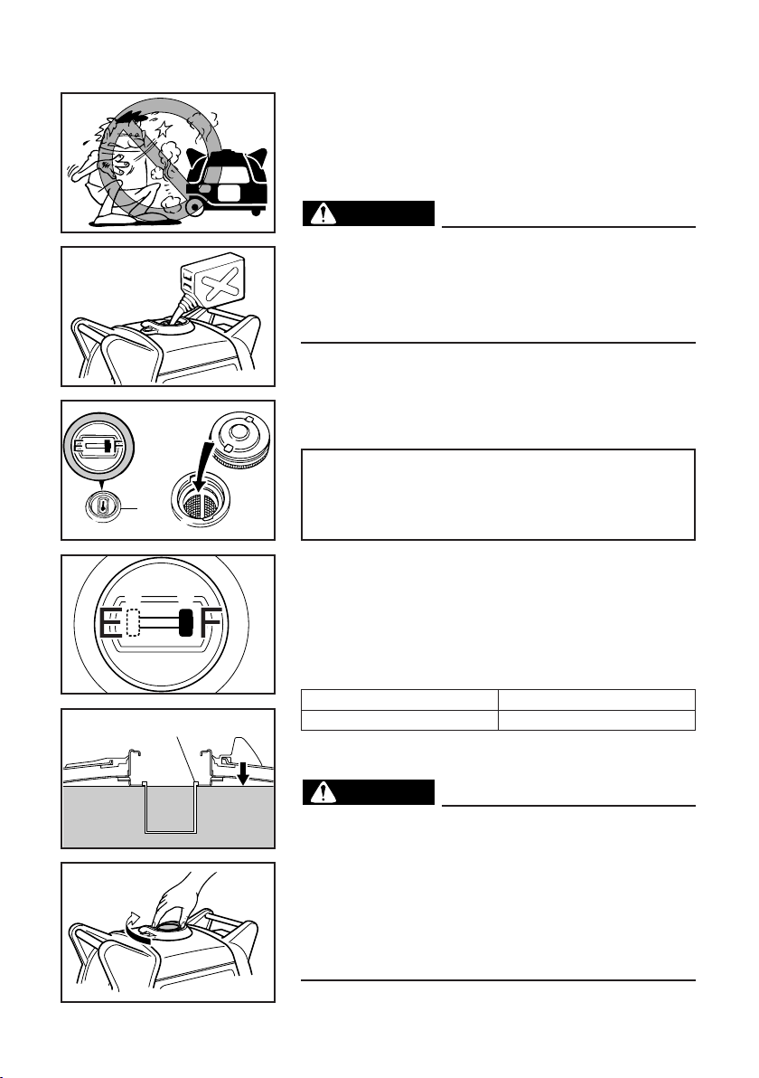
FUEL
Make sure there is sufficient fuel in the tank.
Recommended fuel:
Unleaded gasoline
1
2
3
707-033a
Fuel tank capacity:
Total: 13.0 L (3.43 US gal, 2.86 Imp gal)
Your Yamaha engine has been designed to use regular
unleaded gasoline with a pump octane number ((R +
M)/2) of 86 or higher, or research octane number of 91
or higher.
4
7DF-020
707-101
1 Fuel level gauge
2
“F” Full
3
“E” Empty
4 Fuel filter
9 Fuel is highly flammable and poisonous. Check
“SAFETY INFORMATION” (See page 4) carefully before refueling.
9 Do not fill above the top of the fuel filter or it
may overflow when the fuel warms up and
expands.
9 After refueling, make sure the fuel tank cap is
tightened securely.
– 12 –
700-122
NOTICE
9 Immediately wipe off spilled fuel with a clean,
NOTICE
1
dry, soft cloth, since fuel may deteriorate painted surfaces or plastic parts.
9 Use only unleaded gasoline. The use of leaded
gasoline will cause severe damage to internal
engine parts.
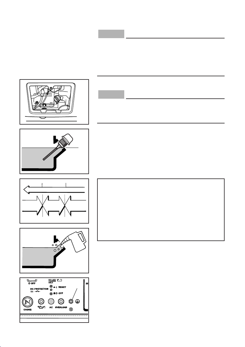
ENGINE OIL
The generator has been shipped without engine oil.
Do not start the engine until you have filled it with
the sufficient engine oil.
Make sure the engine oil is at the upper level of the oil
filler hole. Add oil as necessary.
0°C
å
YAMALUBE 4 (10W-40)
∂
SAE 10Wç SAE #20∫ SAE #30
32°F
25°C
80°F
1
700-103c
700-006
1 Upper level
Recommended engine oil:
å
YAMALUBE 4 (10W-40),
SAE 10W-30 or 10W-40
∫
SAE #30
ç
SAE #20
∂
SAE 10W
Recommended engine oil grade:
API Service SE type or higher
Engine oil quantity:
0.6 L (0.63 US qt, 0.53 Imp qt)
GROUND (earth) TERMINAL
Make sure to ground (earth) the generator.
Check “SAFETY INFORMATION” see page 5.
1 Ground (earth) terminal
– 13 –
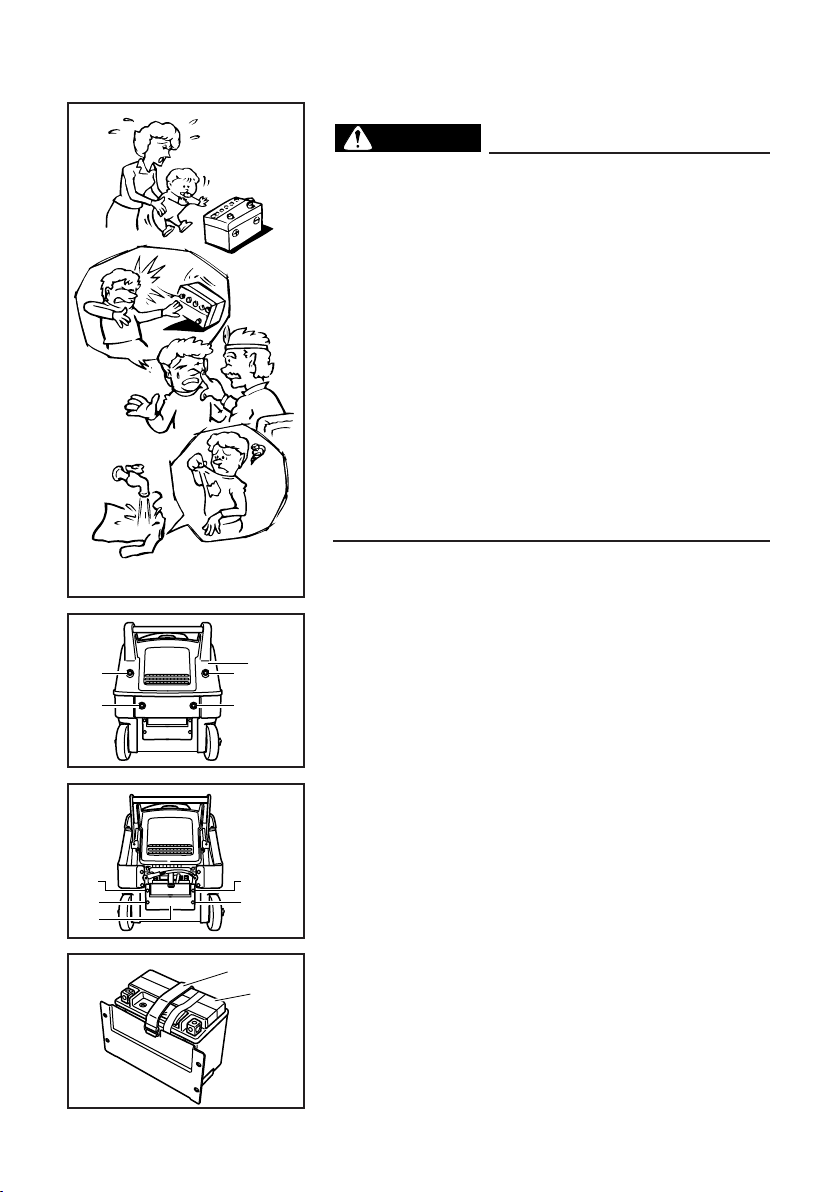
WARNING
788-006
2
1
1
1
1
762-012
BATTERY (For EF3000iSE, EF3000iSEB)
9 Electrolyte is poisonous and dangerous since it
contains sulfuric acid, which causes severe
burns. Avoid any contact with skin, eyes or
clothing and always shield your eyes when
working near batteries. In case of contact,
administer the following FIRST AID.
9 EXTERNAL: Flush with plenty of water.
9 INTERNAL: Drink large quantities of water or
milk and immediately call a physician.
9 EYES: Flush with water for 15 minutes and
seek prompt medical attention.
9 Batteries produce explosive hydrogen gas.
Therefore, keep sparks, flames, cigarettes, etc.,
away from the battery and provide sufficient
ventilation when charging it in an enclosed
space.
9 KEEP THIS AND ALL BATTERIES OUT OF THE
REACH OF CHILDREN.
Installation
1. Remove the bolts and the cover.
1 Bolts
2 Cover
2. Remove the bolts and the battery box.
3 Bolts
4 Battery box
3
3
4
3
3
788-007
5
6
3. Remove the battery band and the battery.
5 Battery band
6 Battery
4. Fill the battery with the electrolyte.
762-044
Refer to the instruction sheet included with the
electrolyte for filling instructions.
– 14 –