


SERVICE MANUAL
EF3000iSE
7WL-28197-E0
310140
FOREWORD
HOW TO USE THIS MANUAL
This manual was written by the Yamaha Motor
Company primarily for use by Yamaha dealers
and their qualified mechanics. It is not possible
to put an entire mechanic’s education into one
manual, so it is assumed that persons using
this book to perform maintenance and repairs
on Yamaha generators have a basic understanding of the mechanical precepts and procedures inherent to generator repair
technology. Without such knowledge,
attempted repairs or service to this model may
render it unfit for use and/or unsafe.
Yamaha Motor Company Ltd. is continually
striving to further improve all models manufactured by Yamaha. Modifications and significant
changes in specifications or procedures will be
forwarded to all Authorized Yamaha dealers
and will, where applicable, appear in future
editions of this manual.
NOTE:
This Service Manual contains information
regarding periodic maintenance to the emission control system. Please read this material
carefully.
PARTICULARLY IMPORTANT
INFORMATION
This material is distinguished by the following
notation.
The Safety Alert Symbol means ATTENTION!
BECOME ALERT! YOUR SAFETY IS
INVOLVED!
WARNING
Failure to follow WARNING instructions could
result in severe injury or death to the machine
operator, a bystander, or a person inspecting
or repairing the machine.
CAUTION:
A CAUTION indicates special precautions that
must be taken to avoid damage to the
machine.
NOTE:
A NOTE provides key information to make procedures easier or clearer.
EF3000iSE
SERVICE MANUAL
©2002 by Yamaha Motor Co., Ltd.
1st Edition, October 2002
All rights reserved. Any reprinting or
unauthorized use without the written
permission of Yamaha Motor Co., Ltd.
is expressly prohibited.
Printed in Japan
MANUAL FORMAT
The procedures in this manual are organized
in a sequential, step-by-step format. The information has been compiled to provide the
mechanic with an easy to read, handy reference that contains comprehensive explanations of all disassembly, repair, assembly, and
inspection operations.
In this revised format, the condition of a faulty
component will precede an arrow symbol and
the course of action required will follow the
symbol, e.g.,
•Bearings
Pitting/damage → Replace.
EXPLODED DIAGRAM
Each chapter provides exploded diagrams
before each disassembly section for ease in
identifying the correct disassembly and
assembly procedures.
12
GEN
INFO
INSP
ADJ
34
ENG
ELEC
–+
5
SPEC
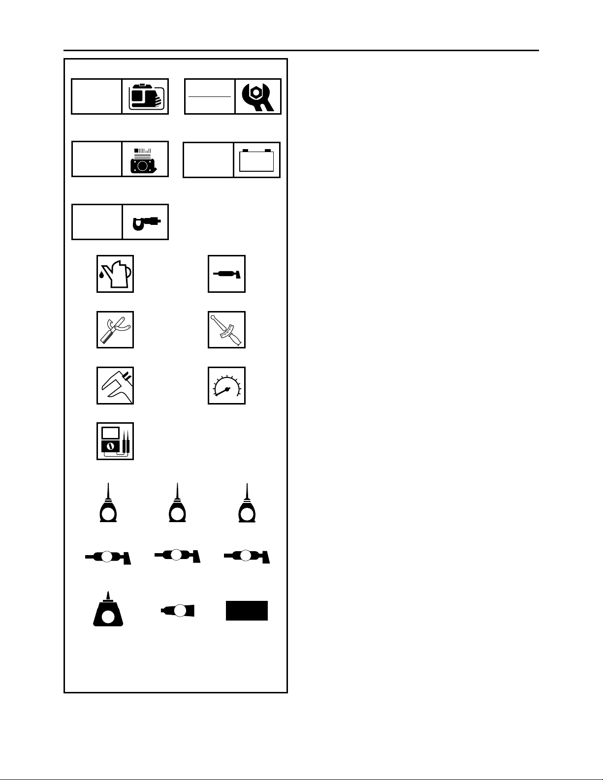
ILLUSTRATED SYMBOLS
(Refer to the illustration)
Illustrated symbols 1 through 5 are designed
as thumb tabs to indicate the chapter’s number
and content.
General information
1
Periodic inspections and adjustments
2
Engine
3
Electrical
4
Specifications
5
67
89
T
.
R
.
0A
B
CDE
E
G
M
FGH
B
LS
M
IJK
LT
4
New
Illustrated symbols 6 through B are used to
identify the specific tools and test equipment.
Filling fluid
6
Lubricant
7
Special tool
8
Tightening
9
Wear limit, clearance
0
Engine speed
A
, V, A
Ω
B
Illustrated symbols C through K in the
exploded diagram indicate the grades of lubricant and the locations of the lubrication points.
Apply engine oil
C
Apply gear oil
D
Apply molybdenum disulfide oil
E
Apply wheel bearing grease
F
Apply lightweight lithium-soap base grease
G
Apply molybdenum disulfide grease
H
Apply a locking agent (LOCTITE
I
Apply Yamaha bond
J
Use a new one
K
®
)
INDEX
GENERAL
INFORMATION
PERIODIC INSPECTIONS
AND ADJUSTMENTS
ENGINE
ELECTRICAL
SPECIFICATIONS

CHAPTER 1.
GENERAL INFORMATION
MACHINE IDENTIFICATION
SERIAL NUMBER ...............................1-1
STARTING SERIAL NUMBER ............ 1-1
IMPORTANT INFORMATION
PREPARATION FOR REMOVAL
AND DISASSEMBLY
CAUTION ON SERVICE ..................... 1-2
NOTES ON SERVICE ......................... 1-2
ALL REPLACEMENT PARTS .............1-3
GASKETS, OIL SEALS,
AND O-RINGS ..................................... 1-3
BEARINGS AND OIL SEALS .............. 1-3
SPECIAL TOOLS AND TESTERS
....................1-1
..................1-2
...........1-4
CHAPTER 2.
PERIODIC INSPECTIONS
AND ADJUSTMENTS
INTRODUCTION
MAINTENANCE INTERVALS CHART
(For Canada)
PERIODIC MAINTENANCE/
LUBRICATION INTERVALS
COVERS, PANELS, AND CAPS
ENGINE
....................................................2-3
ENGINE OIL LEAKAGE CHECKING ..2-3
OIL LEVEL CHECKING ....................... 2-3
OIL REPLACEMENT ...........................2-4
FUEL LEAKAGE .................................. 2-5
FUEL TANK FILTER ...........................2-6
FUEL PIPE STRAINER ....................... 2-7
AIR FILTER ELEMENT .......................2-8
MUFFLER ............................................2-9
VALVE CLEARANCE
ADJUSTMENT ..................................2-10
AIR GAP BETWEEN TCI UNIT
AND FLYWHEEL MAGNETO ...........2-13
COMPRESSION PRESSURE ...........2-14
ENGINE SPEED (NO LOAD) ............ 2-16
ECONOMY ENGINE SPEED ............ 2-16
CHOKE CABLE ................................. 2-17
BREATHER HOSE ............................2-17
.......................................2-1
............................................2-1
....................2-1
..............2-2
ELECTRICAL
SPARK PLUG ................................... 2-18
MAIN SWITCH .................................. 2-19
ECONOMY SWITCH ........................ 2-20
PILOT LIGHT .................................... 2-20
OVERLOAD WARNING LIGHT ........ 2-20
DC CIRCUIT BREAKER ................... 2-21
DC CIRCUIT BREAKER
(120 V-60 Hz) .................................... 2-21
RECEPTACLE .................................. 2-22
AC SWITCH (NFB)
(120 V-60 Hz/23.5 A) ........................ 2-22
AC SWITCH (NFB)
(120 V-60 Hz/15 A) ........................... 2-23
FUSES .............................................. 2-23
BATTERY .......................................... 2-25
BATTERY TERMINAL ...................... 2-25
BATTERY ELECTROLYTE ............... 2-26
BATTERY CHARGING ..................... 2-29
......................................... 2-18
CHAPTER 3.
ENGINE
PANELS AND COVERS
CONTROL PANEL
FUEL TANK AND CONTROL BOX
AIR FILTER ASSEMBLY
AND CONTROL UNIT
120 V-60 Hz, 220 V-50 Hz .................. 3-7
AIR FILTER ASSEMBLY, CONTROL UNIT
AND NOISE FILTER
230 V-50 Hz ........................................ 3-8
RECOIL STARTER
AND FLYWHEEL MAGNETO
RECOIL STARTER REMOVAL ........ 3-12
FLYWHEEL MAGNETO
REMOVAL ......................................... 3-12
FLYWHEEL MAGNETO
INSTALLATION ................................. 3-13
RECOIL STARTER
DISASSEMBLY ................................. 3-14
RECOIL STARTER INSPECTION .... 3-14
RECOIL STARTER ASSEMBLY ....... 3-15
ENGINE ASSEMBLY
CHASSIS AND CASTERS
MUFFLER
MUFFLER INSTALLATION ............... 3-20
.............................................. 3-19
.......................... 3-1
................................... 3-3
......... 3-5
.............................. 3-7
................................ 3-8
.................. 3-9
............................. 3-17
..................... 3-18

GENERATOR .........................................3-21
GENERATOR ASSEMBLY
REMOVAL .........................................3-22
GENERATOR ASSEMBLY
INSTALLATION .................................3-23
CYLINDER HEAD COVER
AND CYLINDER HEAD ..........................3-25
CYLINDER HEAD REMOVAL ...........3-26
PUSH ROD INSPECTION ................. 3-26
CYLINDER HEAD INSPECTION ......3-26
CYLINDER HEAD ASSEMBLY ......... 3-27
BREATHER HOSE ............................3-27
VALVE ....................................................3-28
VALVE AND VALVE SPRING
REMOVAL .........................................3-29
VALVE AND VALVE SPRING
INSPECTION .....................................3-29
LOCKER ARM INSPECTION ............3-30
VALVE SEAT INSPECTION .............. 3-31
VALVE LAPPING ..............................3-32
VALVE AND VALVE SPRING
ASSEMBLY .......................................3-33
CRANKCASE COVER
AND CAMSHAFT ...................................3-34
CRANKCASE COVER REMOVAL ....3-35
CAMSHAFT INSPECTION ................3-35
VALVE LIFTER INSPECTION ........... 3-36
CAMSHAFT ASSEMBLY ..................3-36
CRANKCASE COVER
INSPECTION .....................................3-36
CRANKCASE COVER
INSTALLATION .................................3-36
PISTON, CONNECTING ROD,
CRANKSHAFT AND CRANKCASE ...... 3-37
CRANKCASE (CYLINDER)
INSPECTION .....................................3-38
PISTON AND PISTON PIN
INSPECTION .....................................3-38
PISTON RING INSPECTION ............ 3-40
CRANKSHAFT INSPECTION ........... 3-41
CONNECTING ROD OIL
CLEARANCE INSPECTION .............. 3-42
PISTON RING
AND PISTON ASSEMBLY ................3-43
CRANKSHAFT ASSEMBLY ..............3-44
CARBURETOR ...................................... 3-45
FLOAT HEIGHT INSPECTION ......... 3-49
CHOKE CABLE INSTALLATION ...... 3-50
THROTTLE CONTROL MOTOR ...... 3-50
TROUBLESHOOTING ........................... 3-51
THROTTLE CONTROL SYSTEM ..... 3-56
CHAPTER 4.
ELECTRICAL
ELECTRICAL COMPONENTS ................ 4-1
120 V-60 Hz ........................................ 4-1
220 V-50 Hz ........................................ 4-2
230 V-50 Hz ........................................ 4-3
SWITCHES ............................................... 4-4
CHECKING SWITCH CONTINUITY ... 4-4
IGNITION SYSTEM .................................. 4-5
TROUBLESHOOTING CHART ........... 4-5
ELECTRIC STARTING SYSTEM ........... 4-11
TROUBLESHOOTING CHART ......... 4-11
STARTER MOTOR ........................... 4-14
CHARGING SYSTEM ............................ 4-17
TROUBLESHOOTING CHART ......... 4-17
GENERATOR SYSTEM ......................... 4-20
TROUBLESHOOTING CHART ......... 4-20
CHAPTER 5.
SPECIFICATIONS
GENERAL SPECIFICATIONS ................. 5-1
MAINTENANCE SPECIFICATIONS ........ 5-4
ENGINE .............................................. 5-4
GENERATOR AND ELECTRICAL ...... 5-7
LUBRICATION POINTS
AND LUBRICANT TYPES ....................... 5-8
TIGHTENING TORQUE ........................... 5-9
GENERAL TORQUE
SPECIFICATIONS ................................. 5-11
DEFINITION OF UNITS ......................... 5-11
WIRE ROUTING DIAGRAM ................... 5-12
1
MACHINE IDENTIFICATION
GENERAL INFORMATION
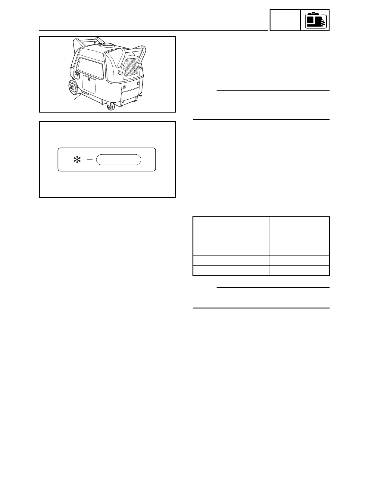
MACHINE IDENTIFICATION
SERIAL NUMBER
The serial number is printed on a label
which is affixed to the generator as shown.
NOTE:
The first three characters of this number are
SWL1010T
for model identification, the remaining digits
are the unit production number.
GEN
INFO
1
SWL1020J
STARTING SERIAL NUMBER
Model Code
120 V-60 Hz 7WL2 7WL-220101~
220 V-50 Hz 7WL3 7WL-330101~
230 V-50 Hz 7WL3 7WL-300101~
230 V-50 Hz 7WL3 7WL-350101~
NOTE:
Designs and specifications are subject to
change without notice.
Starting serial
number
1-1
SVU1030
SVU1040
SVU1050
GEN
IMPORTANT INFORMATION
IMPORTANT INFORMATION
PREPARATION FOR REMOVAL AND DISASSEMBLY
CAUTION ON SERVICE
1. Fire prevention
When servicing the engine, always keep the engine and yourself
away from fire.
NOTES ON SERVICE
1. Correct tools
Be sure to use the correct special tool for the job to guard
against damage.
2. Oil, grease and seals
Be sure to use genuine Yamaha oils, grease and sealers, or the
equivalents.
INFO
SVU1060
SVU1070
SVU1080
3. Expendable parts
Always replace the gaskets, O-rings, cotter pins and circlips with
new parts when servicing engine.
4. Tightening torque
Be sure to follow torque specifications. When tightening bolts,
nuts or screws, start with the largest-diameter fastener and work
from an inner position to an outer position in a crisscross pattern.
5. Notes on disassembly and assembly
a. Parts should be cleaned in solvent and blown dry with com-
pressed air after disassembly.
SVU1090
SVU1100
b. Contact surfaces of moving parts should be oiled when reas-
sembled.
c. Make sure that the parts move smoothly after each section of
the machine is assembled.
1-2
SVU1110
GEN
IMPORTANT INFORMATION
ALL REPLACEMENT PARTS
We recommend the use of genuine Yamaha parts for all replacements. Use oil and/or grease, recommended by Yamaha, for
assembly and adjustment.
GASKETS, OIL SEALS, AND O-RINGS
1. All gaskets, seals, and O-rings should be replaced when an
engine is overhauled. All gaskets surfaces, oil seal lips, and Orings must be cleaned.
2. Properly oil all mating parts and bearings during reassembly.
Apply grease to the oil seal lips.
BEARINGS AND OIL SEALS
Install the bearing(s) 1 and oil seal(s) 2 with their manufacture’s
marks or numbers facing outward. (In other words, the stamped letters must be on the side exposed to view.) When installing oil
seal(s), apply a light coating of light-weight lithium base grease to
the seal lip(s). Oil the bearings liberally when installing.
INFO
SVU1120
CAUTION:
Do not use compressed air to spin the bearings dry. This
causes damage to the bearing surfaces.
1-3
SVU1130
GEN
SPECIAL TOOLS AND TESTERS
SPECIAL TOOLS AND TESTERS
The proper special tools are necessary for complete and accurate
tune-up and assembly. Using the correct special tool will help prevent damage caused by the use of improper tools or improvised
techniques. The shape and part number used for the special tool
differ by country, so two types are provided. Refer to the list provided to avoid errors when placing an order.
NOTE:
• For USA and Canada, use part number starting with “YM-”, “YU-”
or “YS-”.
• For others, use part number starting with “90890-”.
1. Piston ring compressor
P/N. YU-33294, 90890-05158
This tool is used to compress the piston rings when installing the
piston.
INFO
SVU1140
SVU1150
SVU1160
2. Valve spring compressor
P/N. YM-01253, 90890-01253
This tool is used to remove the valve springs.
3. Thickness gauge
P/N. YU-26900-9, 90890-03079
This gauge is used to adjust valve clearance, piston clearance
and piston ring end gap.
4. Cylinder gauge
Commercially available
This instrument is used for checking cylinder bore size and condition.
1-4

SPECIAL TOOLS AND TESTERS
GEN
INFO
1
2
3
4
SWL1010
SWL1020
SWL1040
5. Inductive self-powered tachometer
1
P/N. YU-8036-B
Engine tachometer
2
P/N. 90890-03113
3
P/N. 90793-80009
4
P/N. 90793-80032
This instrument is used for reading engine r/min.
SWL1050
SVU1180
SVU1190
SVU1200
6. Compression gauge 1
P/N. YU-33223, 90890-03081
Adapter 2
P/N. YU-33223-3, 90890-04082
This gauge is used for checking engine compression.
7. Dial gauge
P/N. YU-03097, 90890-03097
This instrument is used for checking crankshaft side clearance.
8. Piston pin puller
P/N. YU-01304, 90890-01304
This tool is used to remove the piston pin.
9. Sheave holder
P/N. YS-01880-A, 90890-01701
This tool is necessary for holding the flywheel or rotor.
SVU1205
1-5
SWL1030
SPECIAL TOOLS AND TESTERS
10.Rotor assembly holder
Commercially available
This tool is necessary for holding the rotor.
GEN
INFO
1
2
1
SVU1210
SVU1220
SVU1230
SVU1240
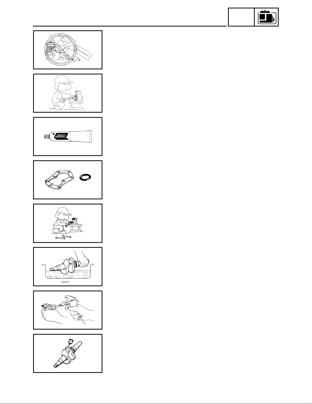
11.Rotor puller
1
P/N. YU-33270-B
2
P/N. 90890-01362
This tool is necessary for removing the flywheel.
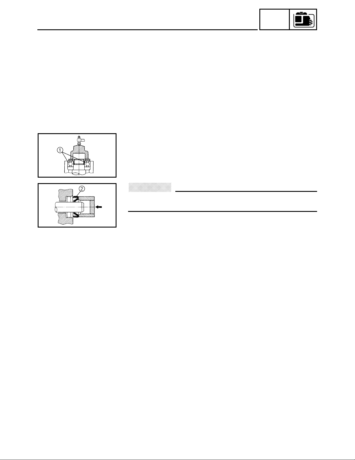
12.Pocket tester
P/N. YU-03112-C, 90890-03112
This instrument is necessary for checking the electrical system.
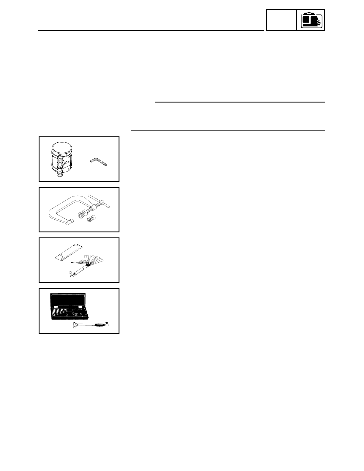
13.Dynamic spark tester 1
P/N. YM-34487
Ignition checker 2
P/N. 90890-06754
This instrument is necessary for checking the ignition system
components.
2
SVU1250
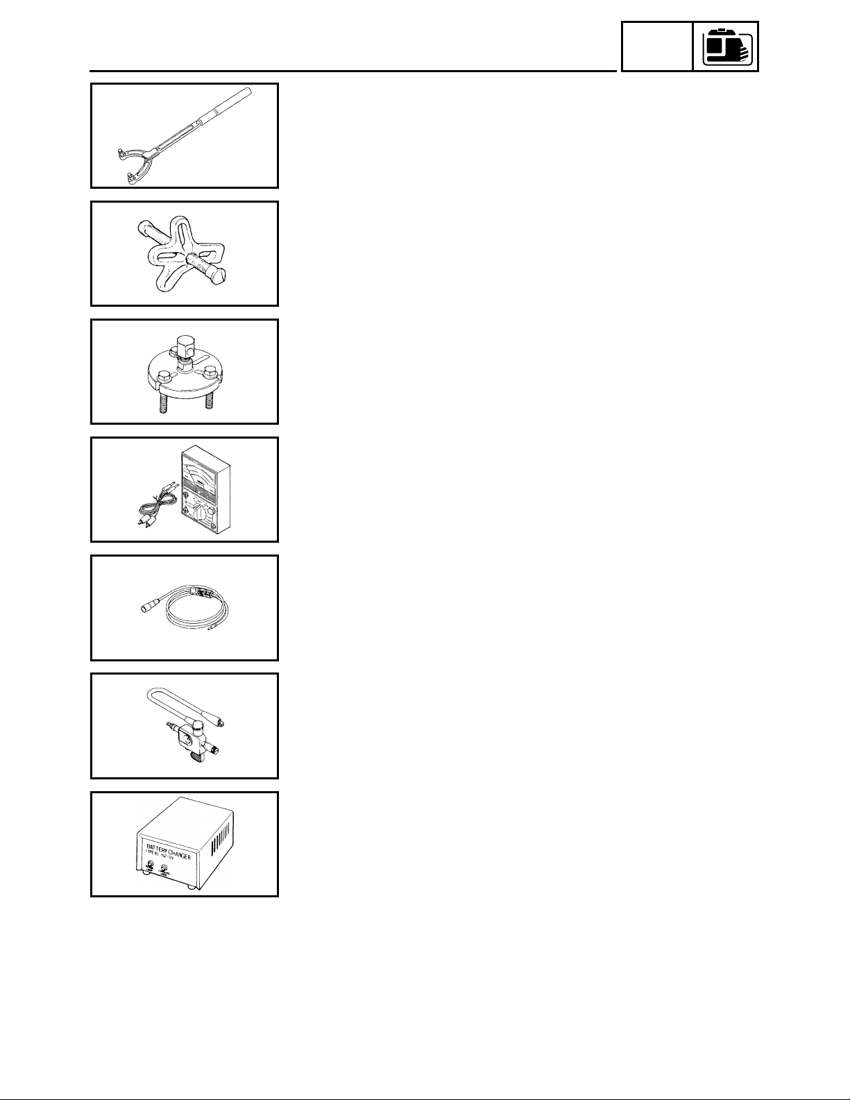
14.MF Battery charging
Commercially available
This instrument is necessary for charging the electrical system.
SWL1060
1-6
INSP
ADJ
INTRODUCTION/MAINTENANCE INTERVALS CHART (For Canada)/
PERIODIC MAINTENANCE/LUBRICATION INTERVALS
PERIODIC INSPECTIONS AND ADJUSTMENTS
INTRODUCTION
This chapter includes all information necessary to perform recommended inspections and adjustments. These preventive maintenance procedures, if followed, will ensure more reliable machine
operation and a longer service life. The need for costly overhaul work will be greatly reduced. This
information applies to machines already in service as well as new machines that are being prepared
for sale. All service technicians should be familiar with this entire chapter.
MAINTENANCE INTERVALS CHART (For Canada)
Proper periodic maintenance is important. Especially important are the maintenance services
related to emissions control. These controls not only function to ensure cleaner air but are also vital
to proper engine operation and maximum performance. In the following maintenance tables, the
services related to emissions control are indicated as “*” in the chart.
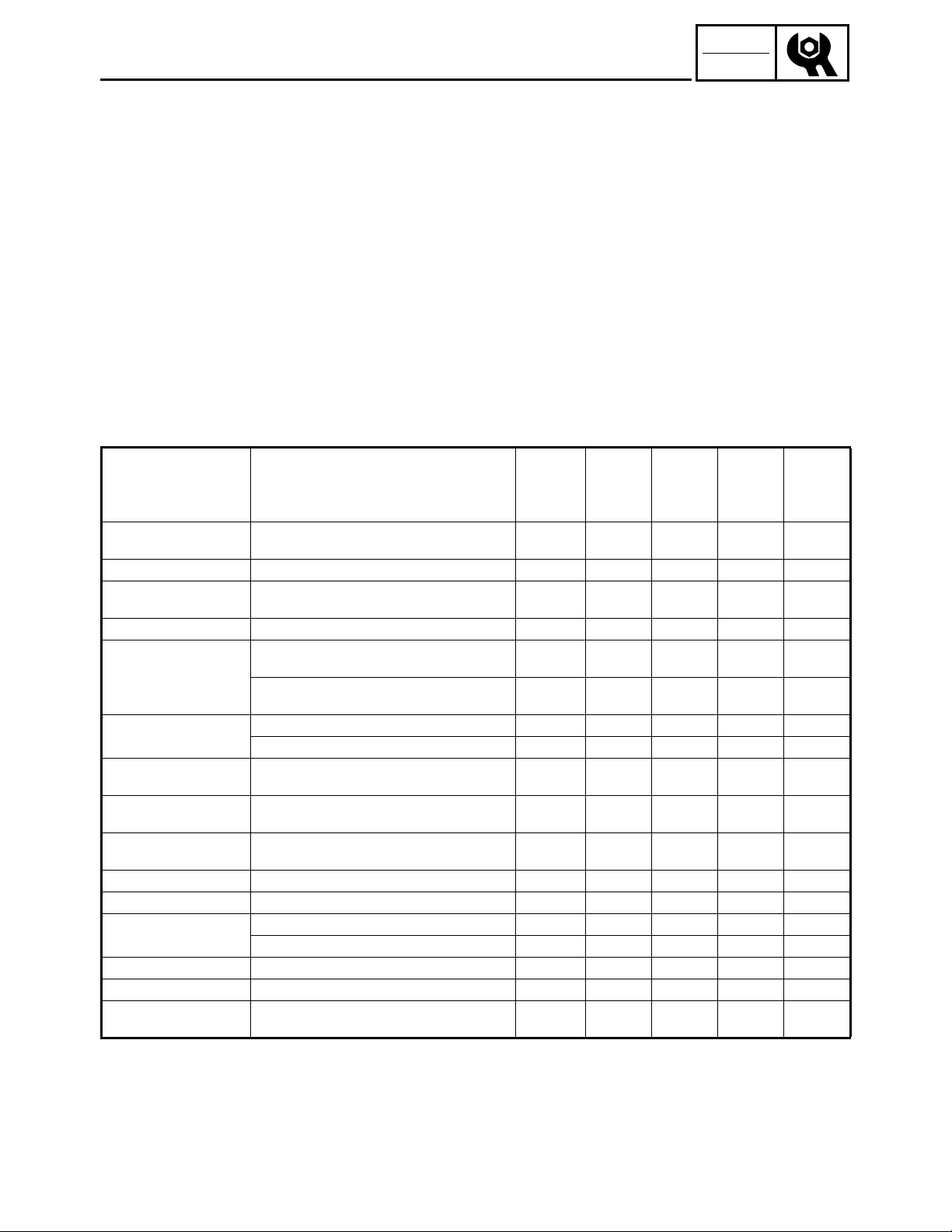
PERIODIC MAINTENANCE/LUBRICATION INTERVALS
ÈÉÊËÌÍ
Item Remarks
Ï
*Spark Plug
Ð
*Valve Clearance Check and adjust when engine is cold.
*Crankcase breather
Ñ
system
Ò
*Idle speed Check and adjust engine idle speed.
Ó
*Exhaust System
Ö
Engine Oil
Ù
*Air Filter
Ú
Fuel Filter
Û
Fuel Line
Ü
*Choke knob Check choke operation.
Ý
Cooling System Check for fan damage.
Þ
Starting System
Á
*Decarbonization More frequently if necessary.
+
Generation Check the pilot light comes on.
,
Fittings/Fasteners
Check condition. Adjust gap and clean.
Replace if necessary.
Check breather hose for cracks or damage.
Replace if necessary.
Check for leakage.
Ô
Retighten or replace gasket if necessary.
Check muffler screen and spark arrester.
Õ
Clean/replace if necessary.
×
Check oil level.
Ø
Replace.
Clean.
Replace if necessary.
Clean fuel tank filter.
Replace if necessary.
Check fuel hose for crack or damage. Replace
if necessary.
ß
Check recoil starter operation.
À
Check electric starter operation.
Check all fittings and fasteners.
Correct if necessary.
Pre-Opera-
tion check
(daily)
●
●
●
●
●
●
●
Î
Initial
1 month
or 20 Hr
●●
Every
3 months
or 50 Hr
●
●
Every
6 months
or 100 Hr
●
●
Every
12 months
or 300 Hr
●
●
●
●
●
●
*: Related to emission control system.
2-1
INSP
ADJ
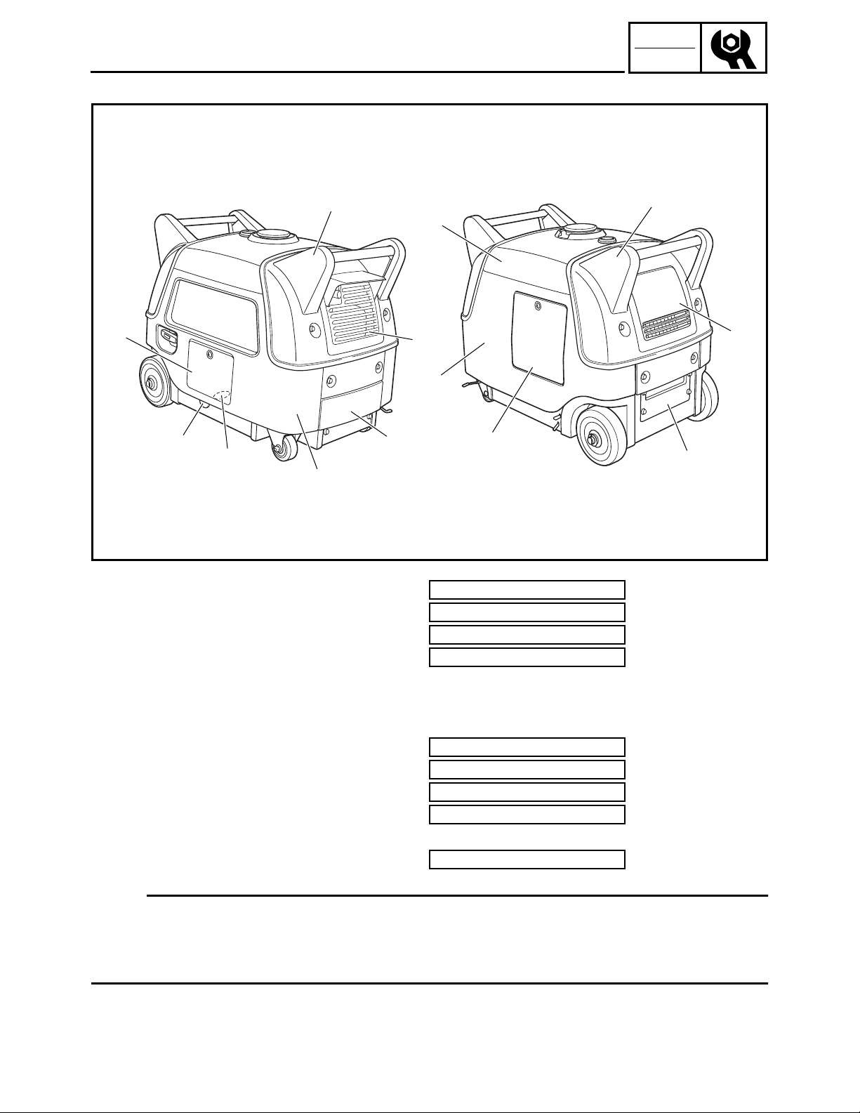
COVERS, PANELS, AND CAPS
COVERS, PANELS, AND CAPS
7
Front right view
6
5
4
1
3
2
Rear left view
9
8
0
C
B
A
SWL2180T
1
Cover 1
2
Panel 1
3
Cover 2
4
Cover 3
5
Cap 1
6
Cap 2
7
Panel 2
8
Cover 4
9
Cover 5
0
Panel 3
A
Battery bracket
B
Panel 4
C
Cover 6
7.0 Nm (0.7 m · kg, 5.1 ft · lb)
7.0 Nm (0.7 m · kg, 5.1 ft · lb)
7.0 Nm (0.7 m · kg, 5.1 ft · lb)
7.0 Nm (0.7 m · kg, 5.1 ft · lb)
7.0 Nm (0.7 m · kg, 5.1 ft · lb)
7.0 Nm (0.7 m · kg, 5.1 ft · lb)
7.0 Nm (0.7 m · kg, 5.1 ft · lb)
7.0 Nm (0.7 m · kg, 5.1 ft · lb)
7.0 Nm (0.7 m · kg, 5.1 ft · lb)
NOTE:
• The EF3000iSE are equipped with soundproof covers and panels that cover the engine and
frame.
• To make periodic maintenance checks easy, remove the applicable cover or panel.
• For cover or panel removal and installation, refer to “PANELS AND COVERS” in CHAPTER 3.
2-2
INSP
ADJ
ENGINE OIL LEAKAGE CHECKING/
OIL LEVEL CHECKING
ENGINE
ENGINE OIL LEAKAGE CHECKING
1. Remove:
• Panel 2
• Panel 4
Refer to “COVERS, PANELS, AND
CAPS”.
2. Check the areas outside of the engine for
SWL2020J
oil leakage.
Oil leakage → Replace the gasket, oil
seal, or O-ring.
3. Install:
• Panel 4
• Panel 2
Refer to “COVERS, PANELS, AND
CAPS”.
1
a
1
SWL2010T
SWL2040J
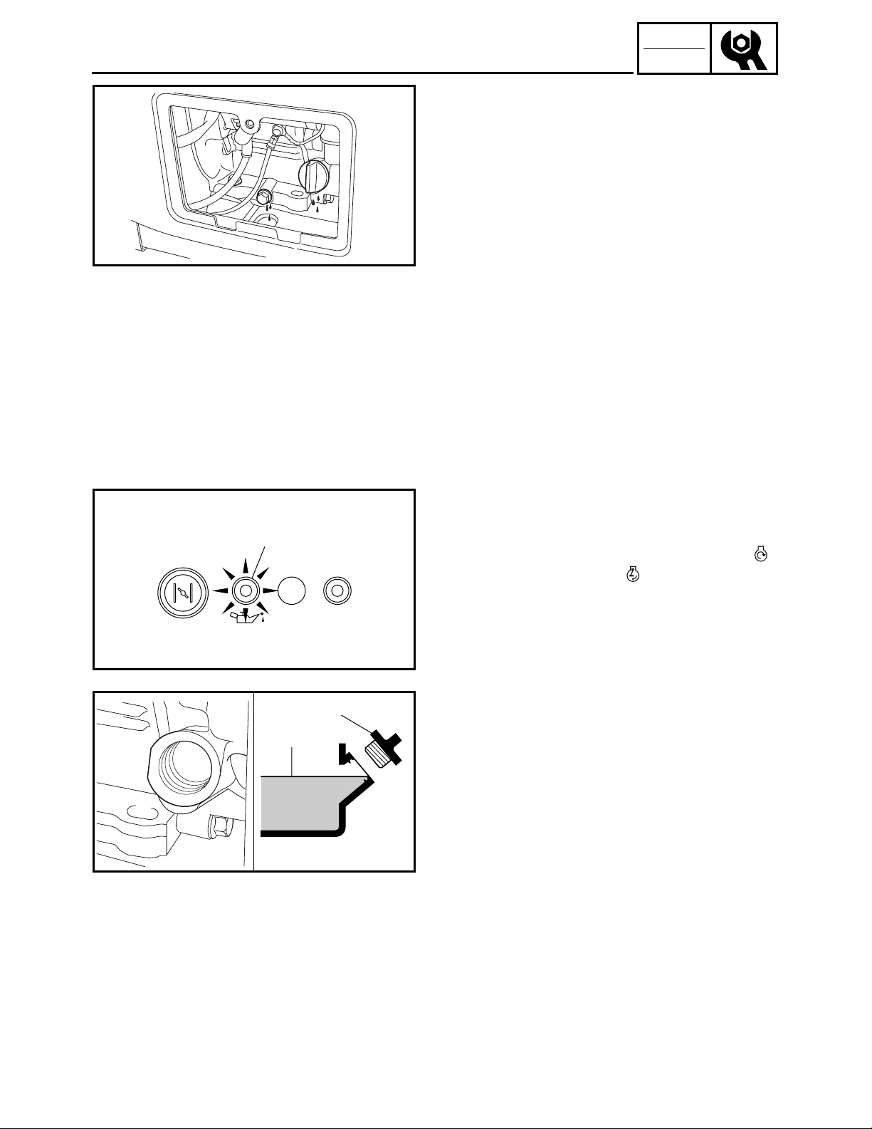
OIL LEVEL CHECKING
1. Check:
• Oil level with oil level warning light 1
• Set the main switch to “START” “”
or set it to “ON” “” and pull the recoil
starter to check that the oil level warning light 1 flashes.
Oil level warning light flashes → Add
oil.
Oil level warning light does not flash
OK
2. Remove:
• Panel 2
Refer to “COVERS, PANELS, AND
CAPS”.
• Oil filler cap 1
3. Check:
• Check that the engine oil is at the specified level a.
Oil level checking steps:
• Place the generator on a level surface.
• Warm up the engine for several minutes.
• Stop the engine.
• Check that the engine oil is at the specified
level a. Add oil if necessary.
→
2-3
INSP
ADJ
OIL LEVEL CHECKING/
OIL REPLACEMENT
4. Install:
• Oil filler cap
• Panel 2
Refer to “COVERS, PANELS, AND
CAPS”.
NOTE:
Tighten the oil filler cap securely by hand.
OIL REPLACEMENT
1. Warm up the engine for several minutes.
2. Stop the engine.
3. Remove:
• Panel 2
• Cap 2
• Cap 1
Refer to “COVERS, PANELS, AND
CAPS”.
4. Place a receptacle under the engine.
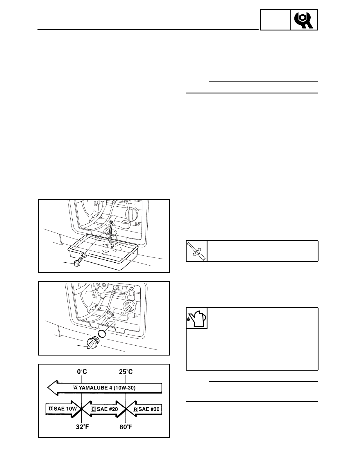
5. Remove:
• Oil drain bolt
6. Tilt the engine to drain the oil completely.
7. Tighten:
• Oil drain bolt
1
SWL2060J
È
1
1
SWL2050J
Oil drain bolt:
17 Nm (1.7 m · kg, 12 ft · lb)
T
.
R
.
8. Remove:
• Oil filler cap 1
9. Fill:
Recommended oil:
È YAMALUBE 4 (10W-30) or SAE
10W-30 type SE
É SAE #30
Ê SAE #20
Ë SAE 10W
Engine oil quantity:
0.6 L (0.53 Imp qt, 0.63 US qt)
NOTE:
Recommended engine oil classification:
API Service “SE” or “SF”, if not available, “SD”.
SVU2060
2-4

INSP
ADJ
OIL REPLACEMENT/
FUEL LEAKAGE
É
SVW2070T
Recommended oil:
SAE #30 or 10W-30
È
or 10W-40
SAE #20 or 10W-30
É
or 10W-40
SAE 10W or 10W-30
Ê
or 10W-40
SAE #40: Above 35 °C (95 °F)
Engine oil quantity:
0.6 L (0.53 Imp qt, 0.63 US qt)
NOTE:
Recommended engine oil classification:
API Service “SE” or “SF”, if not available, “SD”.
For Canada
È
Except for Canada
É
10.Install:
• Oil filler cap
NOTE:
Tighten the oil filler cap securely by hand.
11.Install:
• Cap 1
• Cap 2
• Panel 2
Refer to “COVERS, PANELS, AND
CAPS”.
FUEL LEAKAGE
1. Remove:
• Cover 1
• Cover 5
• Cover 4
Refer to “COVERS, PANELS, AND
CAPS”.
2. Remove:
• Fuel tank bolts
Refer to “FUEL TANK AND CONTROL
BOX” in CHAPTER 3.
3. Slide the fuel tank to check for leakage.
CAUTION:
When sliding the fuel tank, be sure not to
extremely bend, twist, or pull the fuel
hoses.
2-5
INSP
ADJ
SWL2070J
FUEL LEAKAGE/
FUEL TANK FILTER
4. Check:
• Leakage
Check at fuel tank, fuel cock, fuel
hoses, and carburetor.
CAUTION:
Replace the fuel hoses every four years.
5. Install:
• Fuel tank
Refer to “FUEL TANK AND CONTROL
BOX” in CHAPTER 3.
6. Install:
• Cover 4
• Cover 5
• Cover 1
Refer to “COVERS, PANELS, AND
CAPS”.
1
2
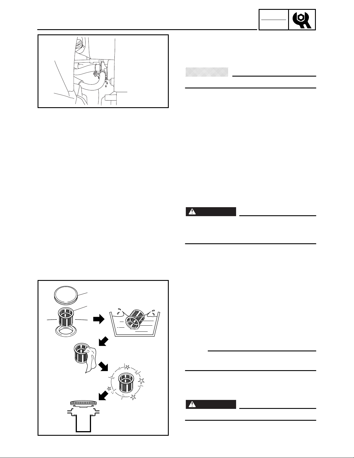
FUEL TANK FILTER
WARNING
Do not smoke, and keep away from open
flames, sparks, or any other source of fire
when handling or in the vicinity of fuel.
1. Remove:
• Fuel tank cap 1
• Fuel tank filter 2
2. Inspect:
• Fuel tank filter
Damage → Replace.
3. Clean:
• Fuel tank filter
NOTE:
Clean the fuel tank filter with solvent, and then
dry it thoroughly.
4. Install:
• Fuel tank filter
• Fuel tank cap
WARNING
Be sure the tank cap is tightened securely.
SVU2080J
2-6
INSP
ADJ
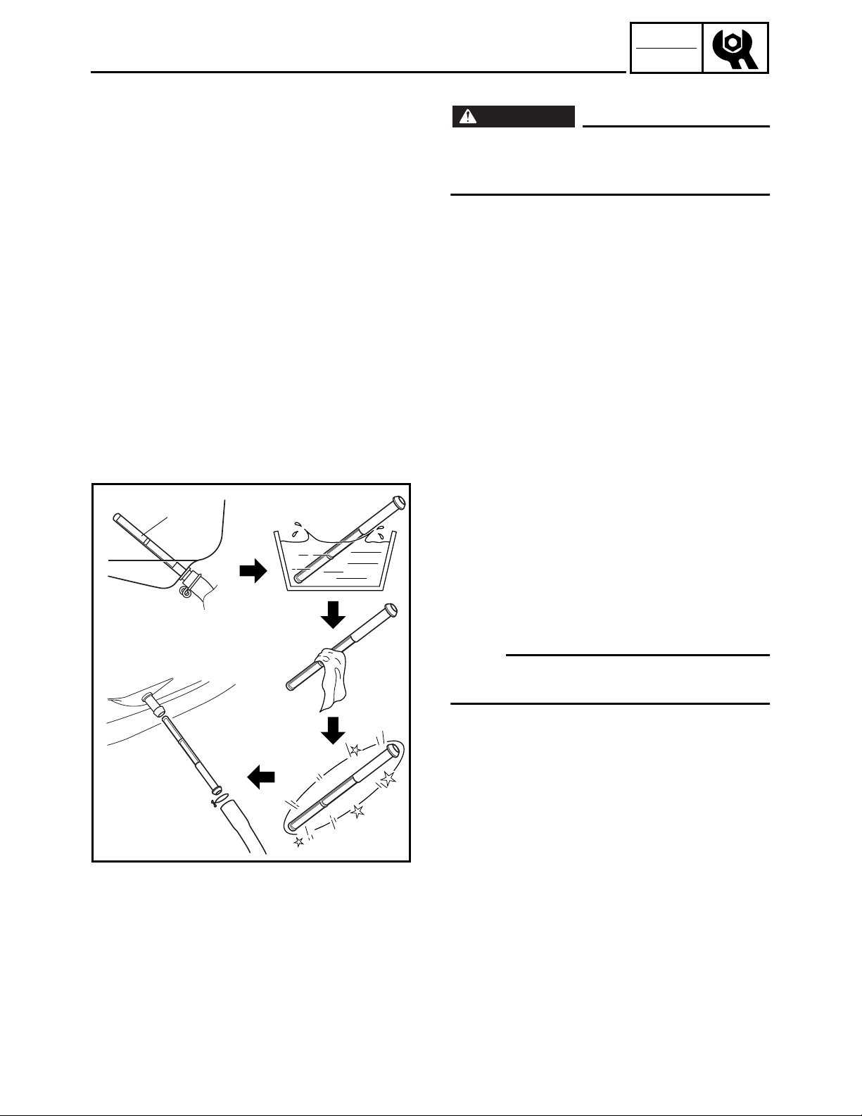
FUEL PIPE STRAINER
FUEL PIPE STRAINER
WARNING
Do not smoke, and keep away from open
flames, sparks, or any other source of fire
when handling or in the vicinity of fuel.
1. Drain the fuel.
2. Remove:
• Cover 1
• Cover 5
• Cover 4
Refer to “COVERS, PANELS, AND
CAPS”.
3. Remove:
• Fuel hose (fuel cock end)
• Fuel tank
Refer to “FUEL TANK AND CONTROL
BOX” in CHAPTER 3.
1
SWL2080J
4. Remove:
• Fuel hose (fuel tank end)
• Fuel pipe strainer 1
5. Inspect:
• Fuel pipe strainer
Damage → Replace.
6. Clean:
• Fuel pipe strainer
NOTE:
Clean the fuel pipe strainer with solvent, and
then dry it thoroughly.
7. Install:
• Fuel pipe strainer
• Fuel hose (fuel tank end)
8. Install:
• Fuel tank
• Fuel hose (fuel cock end)
Refer to “FUEL TANK AND CONTROL
BOX” in CHAPTER 3.
9. Install:
• Cover 4
• Cover 5
• Cover 1
Refer to “COVERS, PANELS, AND
CAPS”.
2-7
INSP
ADJ
AIR FILTER ELEMENT
2
1
1
1
2
SWL2090J
SVU2100J
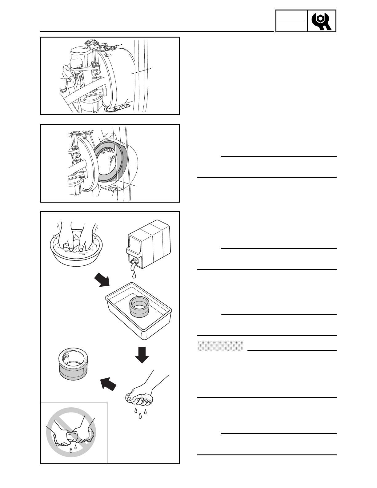
AIR FILTER ELEMENT
1. Remove:
• Panel 4
• Cover 5
Refer to “COVERS, PANELS, AND
CAPS”.
2. Remove:
• Hooks 1
• Air filter element case 2
3. Remove:
• Air filter element 1 1
• Air filter element 2 2
NOTE:
Remove air filter element 1 and air filter element 2 as a set.
4. Inspect:
• Air filter elements
Damage → Replace.
5. Clean:
• Air filter element 1
Wash the air filter elements in kerosene.
NOTE:
Be sure to squeeze the excess kerosene out of
the air filter element 1.
6. Lubricate:
• Air filter element 1
Soak the air filter element 1 in a 2–4:1
mixture of kerosene and engine oil.
NOTE:
Be sure to squeeze the excess kerosene and
engine oil out of the air filter element 1.
CAUTION:
• Do not twist the air filter elements, otherwise they can tear.
• Do not wash the air filter elements in gasoline or in acid, alkaline, or organic solvents.
7. Install:
• Air filter element 1
• Air filter element 2
NOTE:
Insert air filter element 1 into air filter element
2, and then install them into the air filter case.
SWL2110
2-8
INSP
ADJ
AIR FILTER ELEMENT/
MUFFLER
SWL2120J
a
b
2
1
6
2
5
4
3
8. Install:
• Air filter element case 1
• Hooks 2
NOTE:
• Align the projection a of the air filter case
with the slot b in the air filter element
bracket, and then install the air filter case.
• Make sure that the air intake duct 3 is
securely installed onto the frame 4.
• Make sure that the air vent hose 5 and
drain hose 6 are securely installed onto the
frame 4.
9. Install:
• Cover 5
• Panel 4
Refer to “COVERS, PANELS, AND
CAPS”.
1
CAUTION:
The engine should never run without the air
filter element installed, otherwise excessive piston and/or cylinder wear may result.
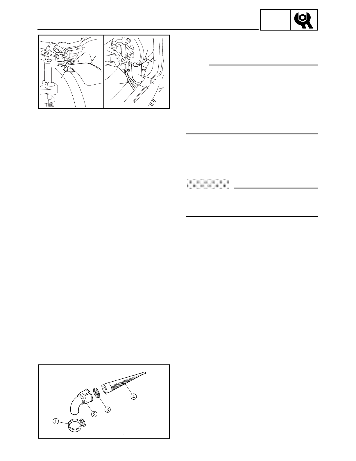
MUFFLER
1. Remove:
• Engine assembly
Refer to “ENGINE ASSEMBLY” in
CHAPTER 3.
2. Remove:
• Muffler
Refer to “MUFFLER” in CHAPTER 3.
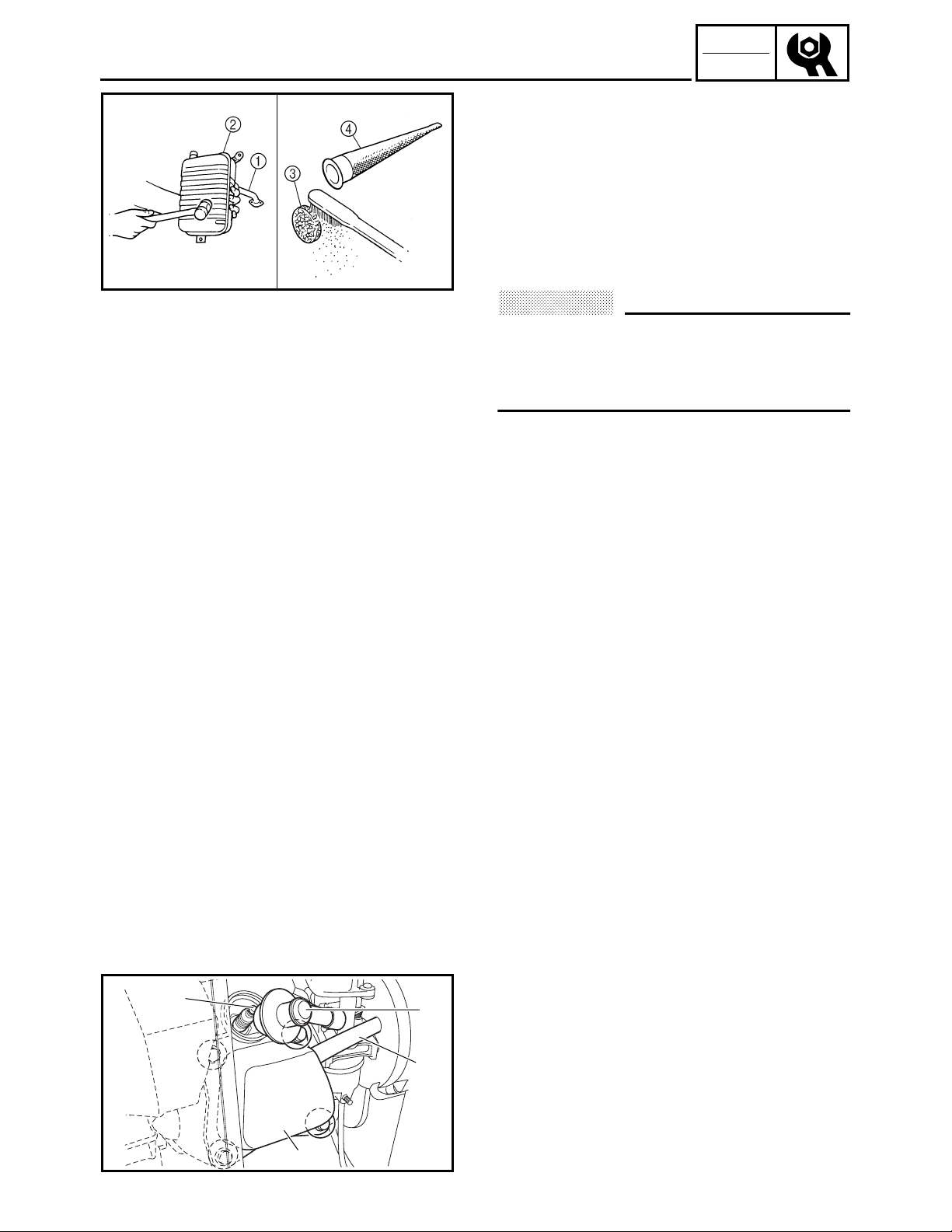
3. Remove:
• Muffler band 1
• Muffler cap 2
• Muffler screen 3
• Spark arrester 4
SWL2400J
2-9
INSP
ADJ
MUFFLER/
VALVE CLEARANCE ADJUSTMENT
4. Decarbonize:
• Exhaust pipe 1
• Muffler 2
• Muffler screen 3
• Spark arrester 4
Tap on the muffler in the area shown in
the illustration to loosen carbon buildup,
and then shake it out of the end of the
SWL2410J
Do not use a wire to clean the muffler, otherwise the noise damping material may
come out, and the damping effect may be
reduced.
muffler.
CAUTION:
5. Install:
• Spark arrester
• Muffler screen
• Muffler cap
• Muffler band
• Muffler
Refer to “MUFFLER” in CHAPTER 3.
6. Install:
• Engine assembly
Refer to “ENGINE ASSEMBLY” in
CHAPTER 3.
4
3
2
1
SWL2130J
VALVE CLEARANCE ADJUSTMENT
1. Remove:
• Panel 4
Refer to “COVERS, PANELS, AND
CAPS”.
2. Remove:
• Breather hose 1
• Spark plug cap 2
• Cylinder head cover 3
• Spark plug 4
2-10

INSP
ADJ
SWL2140J
VALVE CLEARANCE ADJUSTMENT
3. Gently pull the recoil starter to bring the
piston to top dead center of its compression stroke (when the screwdriver
inserted into the spark plug hole reaches
the highest position).
NOTE:
If the piston is at top dead center of the
exhaust stroke, turn the crankshaft one full
turn (360°) to set the piston at top dead center
of the compression stroke.
SWL2150J
4. Measure:
• Valve clearance
Out of specification → Adjust.
NOTE:
Valve clearance must be measured when the
engine is cool to the touch.
Intake valve (cold):
0.18 ~ 0.22 mm (0.007 ~ 0.009 in)
Exhaust valve (cold):
0.18 ~ 0.22 mm (0.007 ~ 0.009 in)
Thickness gauge:
YU-26900-9, 90890-03079
2-11

INSP
ADJ
2
1
VALVE CLEARANCE ADJUSTMENT
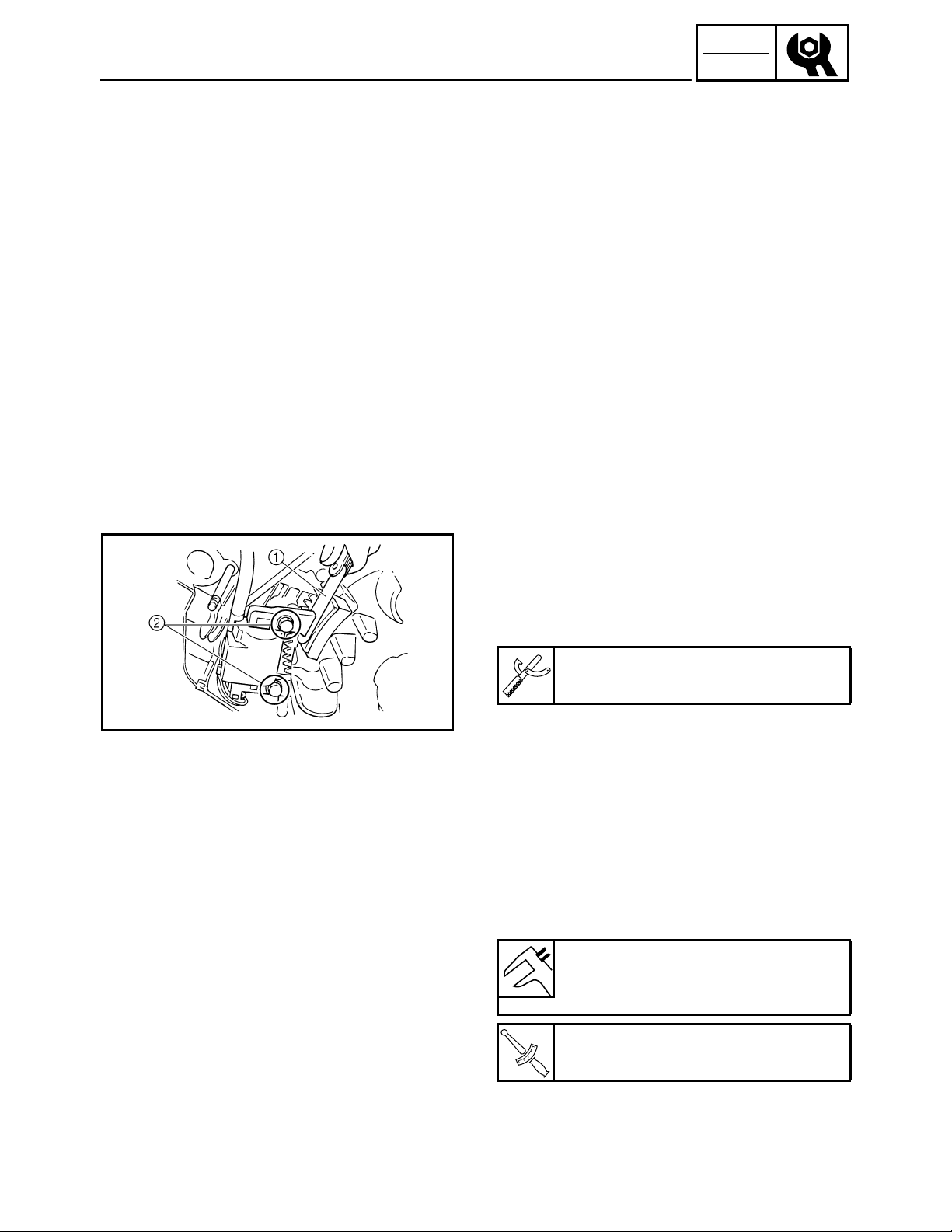
5. Adjust:
• Valve clearance
Adjustment steps:
• Loosen the locknut 1.
• Turn the adjuster 2 in or out to obtain the
proper clearance.
SWL2160J
SWL2170J
1
1
2
2
3
4
SWL2180J
Adjuster Valve clearance
Turn in Decrease
Turn out Increase
• Tighten the locknut 1.
Locknut:
10 Nm (1.0 m · kg, 7.2 ft · lb)
T
.
R
.
6. Install:
• Spark plug 1
• Cylinder head cover 2
• Spark plug cap
3
• Breather hose 4
Cylinder head cover bolt:
10 Nm (1.0 m · kg, 7.2 ft · lb)
T
.
R
.
Spark plug:
18 Nm (1.8 m · kg, 13 ft · lb)
7. Install:
• Panel 4
Refer to “COVERS, PANELS, AND
CAPS”.
2-12
INSP
ADJ
AIR GAP BETWEEN TCI UNIT AND FLYWHEEL
MAGNETO
AIR GAP BETWEEN TCI UNIT AND FLYWHEEL MAGNETO
1. Remove:
• Fuel tank
Refer to “FUEL TANK AND CONTROL
BOX” in CHAPTER 3.
• Air filter element assembly
Refer to “AIR FILTER ASSEMBLY AND
CONTROL UNIT” and “AIR FILTER
ASSEMBLY, CONTROL UNIT AND
NOISE FILTER” in CHAPTER 3.
• Carburetor
Refer to “CARBURETOR” in CHAPTER
3.
• Recoil starter
• Flywheel magneto cover
Refer to “RECOIL STARTER AND FLYWHEEL MAGNETO” in CHAPTER 3.
SWL2420J
2. Measure:
• Air gap between TCI unit and flywheel
magneto
Use a thickness gauge 1.
Out of specification → Adjust.
Thickness gauge:
YU-26900-9, 90890-03079
3. Adjust:
• Air gap between TCI unit and flywheel
magneto
Adjustment steps:
• Loosen the bolts 2.
• Adjust the air gap between the TCI unit
and flywheel magneto by moving the TCI
unit up or down.
• Tighten the bolts 2.
Air gap between TCI unit and flywheel magneto:
0.5 ± 0.1 mm (0.020 ± 0.004 in)
2-13
TCI unit bolt:
10 Nm (1.0 m · kg, 7.2 ft · lb)
T
.
R
.
INSP
ADJ
AIR GAP BETWEEN TCI UNIT AND FLYWHEEL
MAGNETO/COMPRESSION PRESSURE
4. Install:
• Flywheel magneto cover
• Recoil starter
Refer to “RECOIL STARTER AND FLYWHEEL MAGNETO” in CHAPTER 3.
• Carburetor
Refer to “CARBURETOR” in CHAPTER
3.
• Air filter element assembly
Refer to “AIR FILTER ASSEMBLY AND
CONTROL UNIT” and “AIR FILTER
ASSEMBLY, CONTROL UNIT AND
NOISE FILTER” in CHAPTER 3.
• Fuel tank
Refer to “FUEL TANK AND CONTROL
BOX” in CHAPTER 3.
2
1
COMPRESSION PRESSURE
NOTE:
Measure the compression after checking and
adjusting the valve clearance.
1. Warm up the engine for several minutes.
2. Remove:
• Panel 4
Refer to “COVERS, PANELS, AND
CAPS”.
3. Remove:
• Spark plug cap
• Spark plug
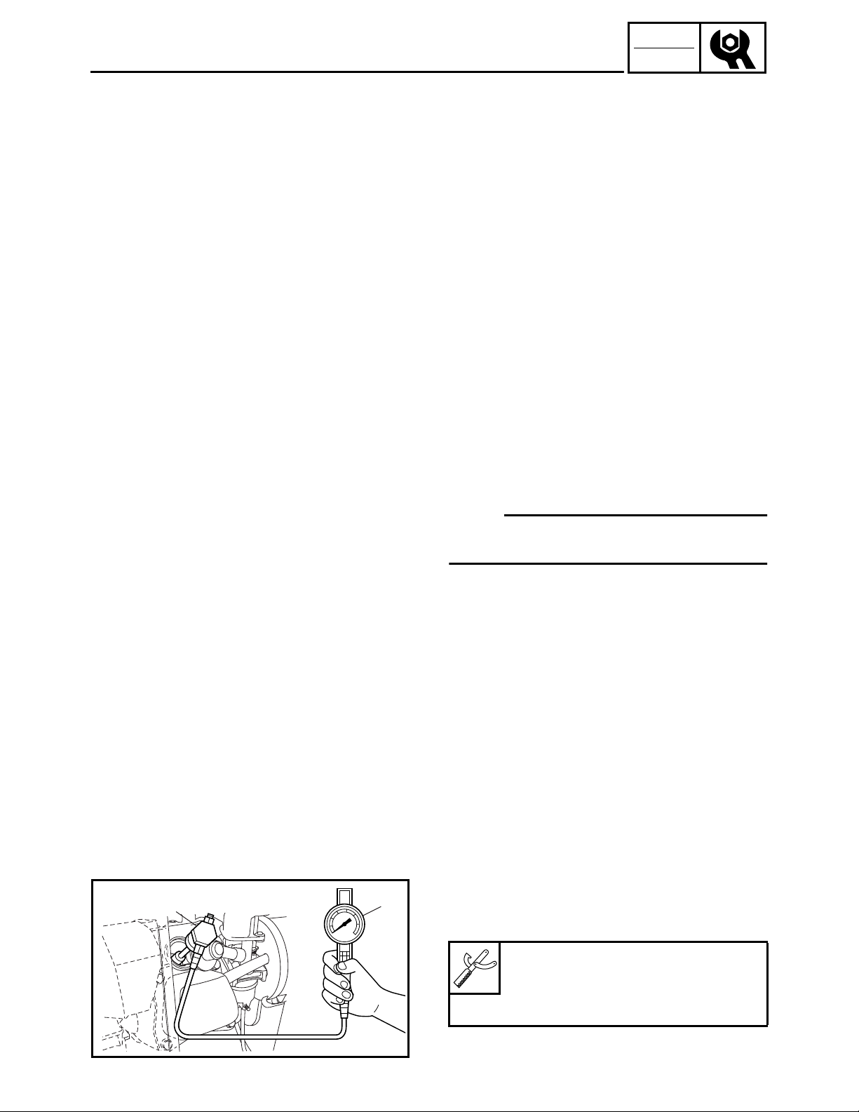
4. Connect:
• Compression gauge 1
• Adapter 2
Compression gauge:
YU-33223, 90890-03081
Adapter:
YU-33223-3, 90890-04082
SWL2190J
2-14
INSP
ADJ
COMPRESSION PRESSURE
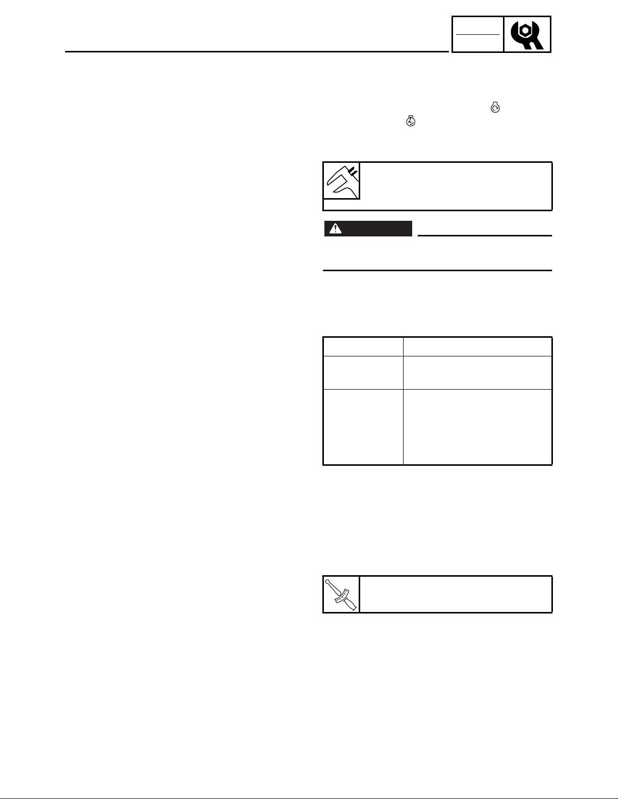
5. Measure:
• Compression
To measure the compression, set the
main switch to “START” “” or set it
to “ON” “” and pull the recoil starter
until the needle stops rising on the compression gauge.
Standard compression pressure:
400 ~ 600 kPa
(4 ~ 6 kg/cm
WARNING
To prevent sparking when cranking the
engine, ground the spark plug lead.
Testing steps (below minimum level):
• Squirt a few drops of oil into the cylinder.
• Measure the compression pressure again.
2
, 57 ~ 85 psi)
Reading Diagnosis
If higher than
without oil
• Worn cylinder, piston, and
piston ring
• Defective piston, ring(s),
If the same as
without oil
valve(s), and cylinder
head gasket
• Improper valve timing and
valve clearance
Testing steps (above maximum level):
• Check the cylinder head, valve surfaces,
and piston crown for carbon deposits.
6. Install:
• Spark plug
• Spark plug cap
Spark plug:
18 Nm (1.8 m · kg, 13 ft · lb)
T
.
R
.
7. Install:
• Panel 4
Refer to “COVERS, PANELS, AND
CAPS”.
2-15
INSP
ADJ
1
ENGINE SPEED (NO LOAD)/
ECONOMY ENGINE SPEED
ENGINE SPEED (NO LOAD)
1. Remove:
• Panel 4
Refer to “COVERS, PANELS, AND
CAPS”.
2. Connect:
• Inductive self-powered tachometer or
engine tachometer
1
SWL2200J
ÈÉ
a
1
a
1
SWL2020T
Inductive self-powered tachometer:
YU-8036-B
Engine tachometer:
90890-03113
(90793-80009, 90793-80032)
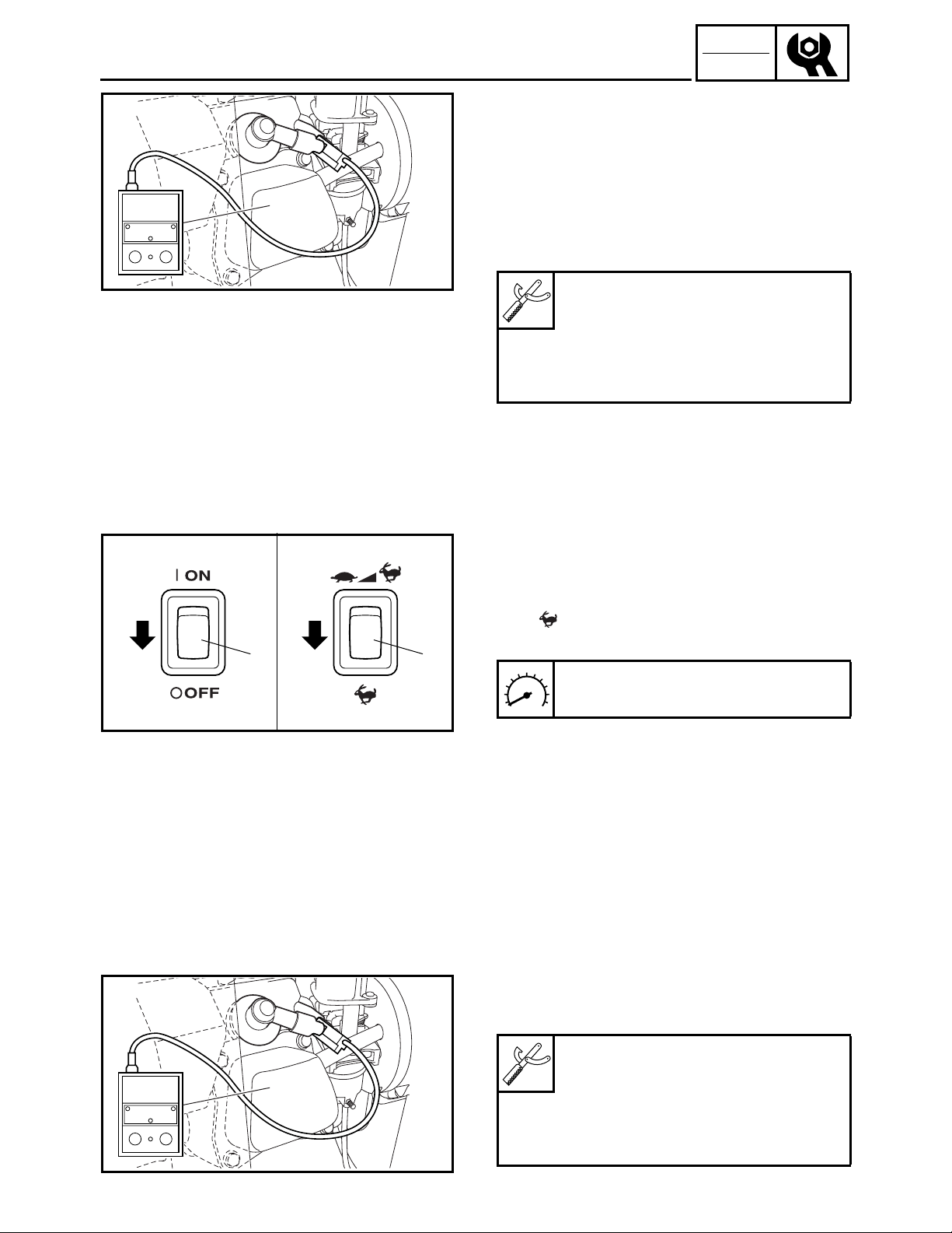
3. Inspect:
• Engine speed (no load)
Specified engine speed → OK
Out of specification → Refer to “TROU-
BLESHOOTING” in CHAPTER 3.
Inspection steps:
• Operate the engine (no load).
• Turn the economy switch 1 to “OFF”
“” a.
• Measure the engine speed (no load).
Engine speed (no load):
3,550 r/min
È
120 V-60 Hz, 220 V-50 Hz
É
230 V-50 Hz
4. Install:
• Panel 4
Refer to “COVERS, PANELS, AND
CAPS”.
ECONOMY ENGINE SPEED
1. Remove:
• Panel 4
Refer to “COVERS, PANELS, AND
CAPS”.
2. Connect:
• Inductive self-powered tachometer or
engine tachometer
1
1
Inductive self-powered tachometer:
YU-8036-B
Engine tachometer:
90890-03113
(90793-80009, 90793-80032)
SWL2200J
2-16

INSP
ADJ
ECONOMY ENGINE SPEED/
CHOKE CABLE/BREATHER HOSE
ÈÉ
a
1
a
1
SWL2050T
3. Inspect:
• Economy engine speed
Specified engine speed → OK
Out of specification → Refer to “TROU-
BLE SHOOTING” in CHAPTER 3.
Inspection steps:
• Turn the economy switch 1 to “ON”
“” a.
• Operate the engine (no load).
• Measure the economy engine speed.
Economy engine speed (no load):
2,800 ± 50 r/min
È
120 V-60 Hz, 220 V-50 Hz
É
230 V-50 Hz
4. Install:
• Panel 4
Refer to “COVERS, PANELS, AND
CAPS”.
CHOKE CABLE
1. Inspect:
• Choke knob
(pull the choke knob all the way out)
Choke knob automatically returns
Adjust.
→
1
SWL2430J
1
SWL2220J
Adjustment steps:
• Turn in the adjusting nut 1 until the choke
knob does not automatically return.
BREATHER HOSE
1. Remove:
• Panel 4
Refer to “COVERS, PANELS, AND
CAPS”.
2. Inspect:
• Breather hose 1
Cracks/damage → Replace.
Poor connection → Correct.
3. Install:
• Panel 4
Refer to “COVERS, PANELS, AND
CAPS”.
2-17
INSP
ADJ
SVU2240J
SPARK PLUG
ELECTRICAL
SPARK PLUG
WARNING
Inspect and adjust the areas around the
cylinder head after the engine has cooled
down completely.
CAUTION:
Before removing the spark plug, use compressed air to clean the cylinder head
cover to prevent dirt from falling into the
engine.
1. Remove:
• Panel 4
Refer to “COVERS, PANELS, AND
CAPS”.
2. Remove:
• Spark plug cap
• Spark plug
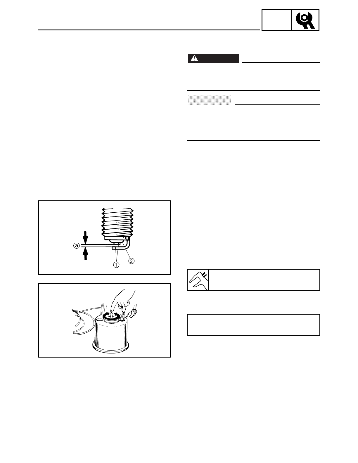
3. Inspect:
• Electrode 1
Wear/damage → Replace.
• Insulator color 2
4. Measure:
• Spark plug gap a
Use a wire gauge or thickness gauge.
Out of specification → Regap.
Spark plug gap:
0.7 ~ 0.8 mm (0.028 ~ 0.031 in)
SVU2250J
If necessary, clean the spark plug with a spark
plug cleaner.
Standard spark plug (with resistor):
BPR4ES (NGK)
Before installing the spark plug, clean the gasket surface and plug surface.
2-18

INSP
ADJ
SVU2280
SPARK PLUG/
MAIN SWITCH
5. Tighten:
• Spark plug
Spark plug:
18 Nm (1.8 m · kg, 13 ft · lb)
T
.
R
.
NOTE:
To prevent thread damage, finger tighten
the spark plug before tightening it to the specified torque b.
6. Install:
• Spark plug cap
7. Install:
• Panel 4
Refer to “COVERS, PANELS, AND
CAPS”.
a
ÈÉ
SWL2030T
ÈÉ
SWL2040T
MAIN SWITCH
1. Check:
• Main switch
Checking steps:
• Set the main switch to “ON” “” and pull
the recoil starter to start the engine.
• Check that the engine stops when the
main switch is set to “STOP” “” 1.
Engine does not stop → Refer to “IGNI-
TION SYSTEM” in CHAPTER 4.
È
120 V-60 Hz, 220 V-50 Hz
É
230 V-50 Hz
• Check that the engine starts when the
main switch is set to “START” “”.
Engine does not start → Refer to “ELEC-
TRIC STARTING SYSTEM” in CHAPTER
4.
È
120 V-60 Hz, 220 V-50 Hz
É
230 V-50 Hz
2-19

INSP
ADJ
ECONOMY SWITCH/PILOT LIGHT/
OVERLOAD WARNING LIGHT
ÈÉ
a
1
a
1
SWL2050T
1
ECONOMY SWITCH
1. Check:
• Economy switch 1
120 V-60 Hz, 220 V-50 Hz
È
230 V-50 Hz
É
Checking steps:
• Set the economy switch 1 to “ON”
“” a.
• Start the engine.
• Turn the switch of the electric device con-
nected to the AC outlet “ON” “”
and “OFF” “” to check whether the
engine speed increases and decreases.
Does not change → Refer to “TROUBLE-
SHOOTING” in CHAPTER 3 and “GENERATOR SYSTEM” in CHAPTER 4.
PILOT LIGHT
1. Check:
• Pilot light 1
1
SWL2060T
SWL2070T
Checking steps:
• Start the engine.
• Check that the pilot light 1 turns on.
Refer to “GENERATOR SYSTEM” in
CHAPTER 4.
OVERLOAD WARNING LIGHT
1. Check:
• Overload warning light 1
2. Remove:
• Control panel
• Overload warning light connector
Refer to “CONTROL PANEL” in CHAPTER 3.
Checking steps:
• Connect three dry cell batteries (1.5 V) to
the overload warning light lead.
• Check that the overload warning light
turns on.
Does not turn on → Replace.
3. Install:
• Overload warning light connector
• Control panel
Refer to “CONTROL PANEL” in CHAPTER 3.
2-20
1

INSP
ADJ
1
DC CIRCUIT BREAKER/
DC CIRCUIT BREAKER (120 V-60 Hz)
DC CIRCUIT BREAKER
1. Check:
• DC circuit breaker
Checking steps:
• Check if the DC circuit breaker knob 1 is
ab
SWL2080T
SWL2090T
set to “RESET” “” a.
• If the knob 1 is set to “OFF” “” b,
direct current cannot be supplied.
• Start the engine.
• Connect a pocket tester (DC 20 V) to the
DC receptacle and check if direct current
is supplied.
Pocket tester:
YU-03112-C, 90890-03112
Direct current not supplied → Replace or
refer to “GENERATOR SYSTEM” in
CHAPTER 4.
1
DC
ON OFF
a
ON
b
SVU2330C
SWL2100T
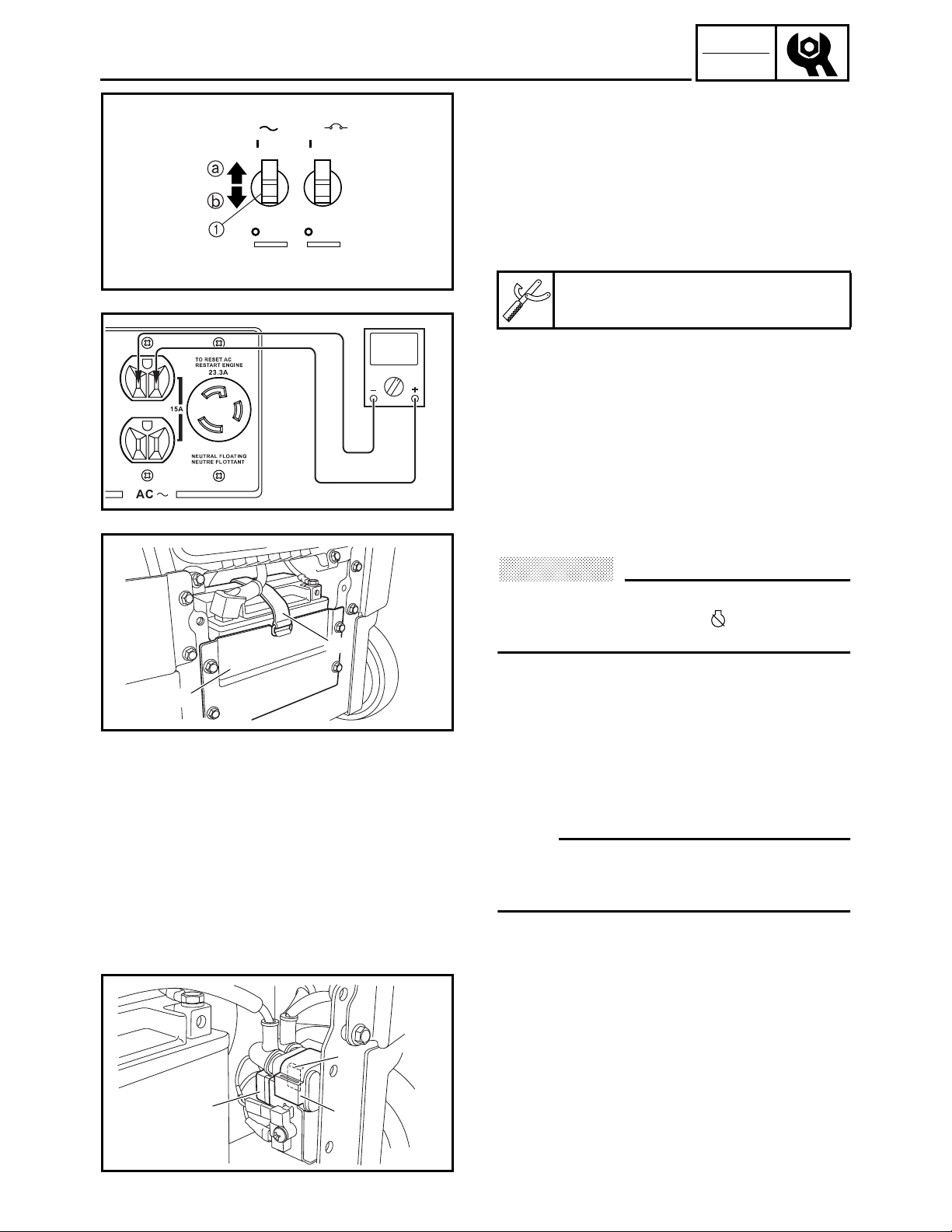
DC CIRCUIT BREAKER (120 V-60 Hz)
1. Check:
• DC circuit breaker
Checking steps:
• Set the DC circuit breaker 1 to the posi-
tion of “ON” a.
• Connect the pocket tester (DC 20 V).
Pocket tester:
YU-03112-C, 90890-03112
• Start the engine.
• Set the economy switch to “OFF”.
• Measure the DC voltage.
DC voltage:
More than 12 V at 3,550 r/min
(no load at AC output current)
• Set the DC circuit breaker 1 to “OFF” b.
Voltage is zero → OK
2-21

INSP
ADJ
RECEPTACLE/
AC SWITCH (NFB) (120 V-60 Hz/23.5 A)
È
É
Ê
1
2
2
3
5
6
4
SWL2110T
SWL2120T
RECEPTACLE
1. Check:
• DC receptacle (12 V, 8.3 A) 1
• DC receptacle (12 V, 12 A) 2
• AC receptacles (15 A) 3
• AC receptacle (23.3 A) 4
• AC receptacles (15 A) 5
• AC receptacles (16 A) 6
Cracks/damage → Replace.
Poor connection → Correct.
120 V-60 Hz
È
220 V-50 Hz
É
230 V-50 Hz
Ê
1
AC SW
ON
ON ON
OFF
15A
ON
OFF
SWL2130T
SWL2160T
SWL2140T
AC SWITCH (NFB) (120 V-60 Hz/23.5 A)
1. Set the AC switch (NFB) 1 to the “ON”
position.
2. Connect the pocket tester (AC 120 V) to
the AC receptacle (23.3 A) and check the
AC switch (NFB) for continuity.
No continuity → Replace the AC switch
(NFB).
Pocket tester:
YU-03112-C, 90890-03112
3. Set the AC switch (NFB) 1 to the “OFF”
b position.
4. Connect the pocket tester (AC 120 V) to
the AC receptacle (23.3 A) and check the
AC switch (NFB) for continuity.
Continuity → Replace the AC switch
(NFB).
a
2-22
INSP
ADJ
AC SWITCH (NFB) (120 V-60 Hz/15 A)/
AC SWITCH (NFB) (120 V-60 Hz/15 A)
AC SW
ON
ON ON
OFF
15A
ON
OFF
SWL2170T
SWL2150T
1. Set the AC switch (NFB) 1 to the “ON”
position.
2. Connect the pocket tester (AC 120 V) to
the AC receptacle (15 A) and check the
AC switch (NFB) for continuity.
No continuity → Replace the AC switch
(NFB).
Pocket tester:
YU-03112-C, 90890-03112
3. Set the AC switch (NFB) 1 to the “OFF”
b
position.
4. Connect the pocket tester (AC 120 V) to
the AC receptacle (15 A) and check the
AC switch (NFB) for continuity.
Continuity → Replace the AC switch
(NFB).
FUSES
a
1
2
3
SWL2280J
FUSES
CAUTION:
To avoid a short circuit, always set the
main switch to “STOP” “” when check-
ing or replacing a fuse.
1. Remove:
• Cover 5
Refer to “COVERS, PANELS, AND
CAPS”.
2. Remove:
• Battery bracket 1
• Battery band 2
• Battery
NOTE:
To check the fuses, slide the battery out with
the positive battery lead and negative battery
lead connected to the battery.
3. Remove:
• Starter relay 1
• Fuse 2
• Fuse (spare)
3
2
1
SWL2290J
2-23

INSP
ADJ
FUSES
4. Check:
• Fuses
Checking steps:
• Connect the pocket tester (
and check the continuity.
NOTE:
Set the pocket tester selector to “
Pocket tester:
YU-03112-C, 90890-03112
• If the pocket tester indicates “∞”, replace
the fuse.
5. Replace:
• Blown fuse
Replacing steps:
• Set the main switch to “STOP” “”.
• Install a new fuse of the correct amperage.
• Set the main switch to “ON” “” and ver-
ify if the electrical circuit is operational.
• If the fuse immediately blows again, check
the electrical circuit.
Ω ×
1) to a fuse
Ω ×
1”
Fuse amperage:
10 A
WARNING
Never use a fuse with an amperage other
than that specified. Improvising or using a
fuse with the wrong amperage rating may
cause extensive damage to the electrical
system and could possibly cause a fire.
6. Install:
• Fuse (spare)
• Fuse
• Starter relay
7. Install:
• Battery
• Battery band
• Battery bracket
8. Install:
• Cover 5
Refer to “COVERS, PANELS, AND
CAPS”.
2-24
INSP
ADJ
DANGER/POISON
EYES
EXPLOSIVE
GASES CAN CAUSE
BLINDNESS OR INJURY
IN U.S.A., YUASA BATTERY, INC,
SERVICED BY : READING, PA. 19612
SHIELD
SPARKS
FLAMES
SMOKING
KEEP OUT OF REACH OF CHILDREN
NO
SULFURIC
ACID
CAN CAUSE
BLINDNESS OR
SEVERE BURNS
FLUSH EYES
IMMEDIATELY
WITH WATER
GET
MEDICAL
HELP
FAST
LEAD
AH17
RETURN
RECYCLE
Pb
SWL2450
BATTERY/
BATTERY TERMINAL
BATTERY
WARNING
Battery fluid is poisonous and dangerous,
causes severe burns, etc. Contains sulfuric
acid.
Avoid contact with skin, eyes or clothing.
Antidote:
EXTERNAL – Flush with water.
INTERNAL – Drink large quantities of water
or milk. Follow with milk of magnesia,
beaten egg or vegetable oil. Call a physician immediately.
Eyes: Flush with water for 15 minutes and
get prompt medical attention.
Batteries produce explosive gases. Keep
sparks, flames, cigarettes, etc. away. Ventilate when charging or using in enclosed
space. Always shield eyes when working
near batteries.
KEEP OUT OF REACH OF CHILDREN.
3
1
2
SWL2300J
SWL2310J
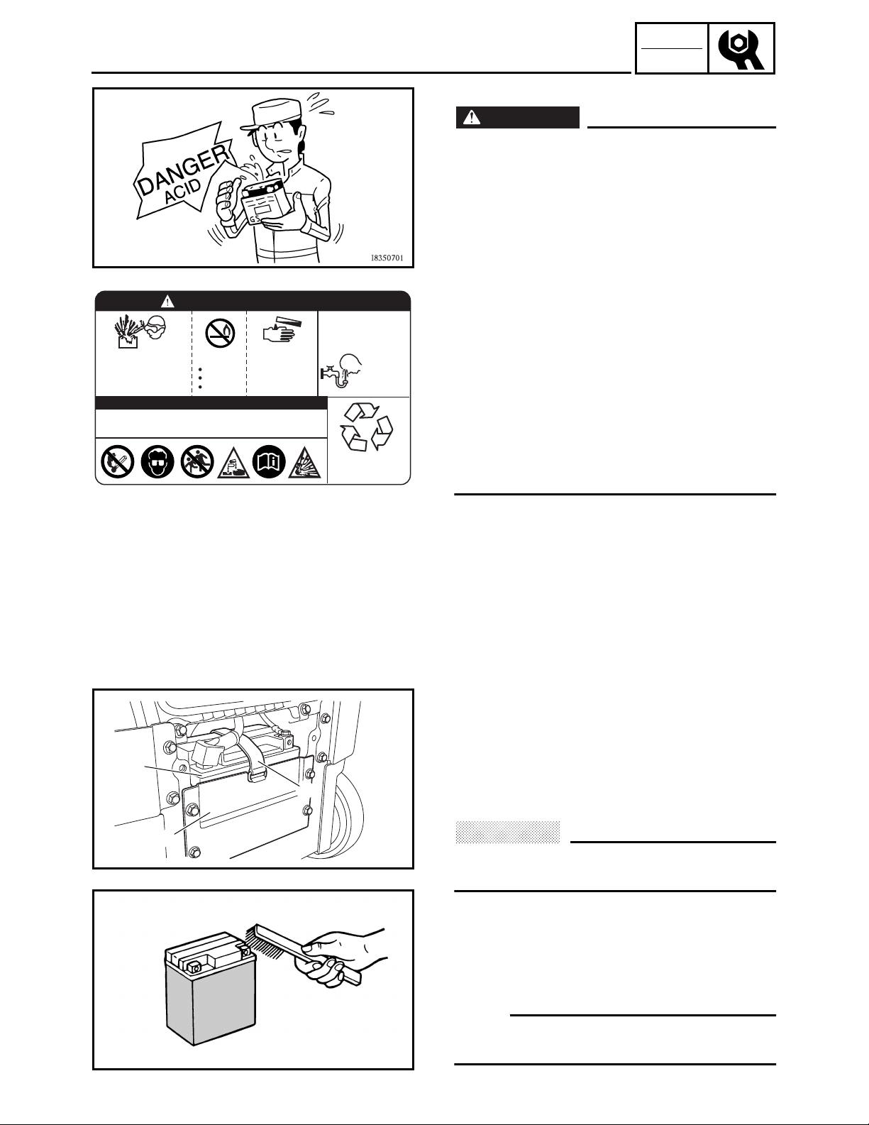
BATTERY TERMINAL
1. Remove:
• Cover 5
Refer to “COVERS, PANELS, AND
CAPS”.
2. Remove:
• Battery bracket 1
• Battery band 2
• Battery 3
CAUTION:
When removing the battery, disconnect the
negative lead first.
3. Check:
• Battery terminal
Dirty terminal → Clean with a wire
brush.
Poor connection → Correct.
NOTE:
After cleaning the terminals, apply grease
lightly to the terminals.
2-25

INSP
ADJ
BATTERY TERMINAL/
BATTERY ELECTROLYTE
4. Install:
• Battery
• Battery band
• Battery bracket
CAUTION:
Connect the positive lead to the battery terminal first.
5. Install:
• Cover 5
Refer to “COVERS, PANELS, AND
CAPS”.
BATTERY ELECTROLYTE
1. Fill:
CAUTION:
• Never remove the sealing sheet (aluminium seal) from the battery until the battery is filled with electrolyte.
If battery plates are exposed to air, they
will oxidize. As a result, power will not be
generated as specified.
• Add electrolyte so that its level is correct
as specified.
An incorrect electrolyte level has an
adverse effect on battery performance.
The quantity of electrolyte varies with the
type of the electrolyte container. Use
only the amount of electrolyte in the container which comes with the battery.
• Avoid using any electrolyte other than
specified.
The specific gravity of the MF battery
electrolyte is 1.320 (20 °C). (The specific
gravity of the general type battery electrolyte is 1.280.)
If the electrolyte whose specific gravity is
less than 1.320, the sulfuric acid will
decrease and thus low battery performance will result.
Should any electrolyte, whose specific
gravity is 1.320 or more, be used, the battery plates will corrode and battery life
will shorten.
2-26

INSP
ADJ
BATTERY ELECTROLYTE
a. Place the battery on a level surface.
b. Remove the sealing sheet 1.
Filler port
2
SWL2320J
c. Take the electrolyte container out of the
vinyl bag.
d. Detach the strip of caps (used as battery
plugs) 1.
Six sealed areas of container
2
NOTE:
Do not lose the strip of caps because it will be
used as battery plugs.
SWL2330J
CAUTION:
Do not peel or pierce the sealed areas.
SWL2340J
e. Turn the electrolyte container upside
down with the six sealed areas in line with
the six filler ports of the battery.
f. Push the container down strongly enough
to break the seals. The electrolyte will
start to flow into the battery.
CAUTION:
• Do not tilt the container as the electrolyte
may stop flowing.
• Never remove the container from the battery until all electrolyte has drained from
the container.
2-27

INSP
ADJ
BATTERY ELECTROLYTE
g. Leave the container in this position for
20 minutes or longer to allow proper
chemical reaction.
NOTE:
• Make sure air bubbles are rising from all six
filler ports.
• If air bubbles are not rising from a filler port,
tap the top of the container a few times.
SWL2350J
SWL2360J
• Do not cut the connected parts.
h. Be certain that all the electrolyte has been
drained from the container.
i. Fit the strip of caps (battery plugs)
securely into the filler ports. Make sure
the top of the strip is at the same level as
the top of the battery.
Press down horizontally with both hands.
1
CAUTION:
Never remove the strip of caps, nor add any
water or electrolyte.
WARNING
• Do not attempt boost charging under any
circumstances.
• Battery electrolyte is poisonous and dangerous, causing severe burns, etc. Contains sulfuric acid. Avoid contact with
skin, eyes or clothing.
Antidote: External — Flush with water.
Internal — Drink large quantities of water
or milk. Follow with milk of magnesia,
beaten egg, or vegetable oil. Call physician immediately.
Eyes: Flush with water for 15 minutes
and get prompt medical attention. Batteries produce explosive gases. Keep
sparks, flame, cigarettes, etc., away. Ventilate when charging or using in enclosed
space. Always shield eyes when working
near batteries.
KEEP OUT OF REACH OF CHILDREN.
2-28

INSP
ADJ
BATTERY ELECTROLYTE/
BATTERY CHARGING
2. Check:
• Using a digital voltmeter, the state of a
discharged MF battery can be checked
by measuring open-circuit voltage (the
voltage measured with the positive and
negative terminals being disconnected).
CAUTION:
The battery must be charged after it is filled
with electrolyte. If this is not done, the life
of the battery will be shortened drastically.
SWL2380J
SWL2390J
BATTERY CHARGING
1. Check:
• Battery voltage
Check the battery voltage using an MF
battery tester (commercially available).
Within green range → Correct
Within yellow or red range → Charge
the battery.
2. Recharge the battery using an MF battery
charger (commercially available).
• Charge the battery to the specified
electric current and to the specified voltage.
Charging amperage and charging time:
1.2 A × 5 ~ 10 hr
Charging voltage:
12.8 V or more
2-29

PANELS AND COVERS
:
7.0 Nm (0.7 m · kg, 5.1 ft · lb)
È
PANELS AND COVERS
ENGINE
È
ENG
È
È
È
5
È
8
2
7
È
4
È
3
1
È
Order Job name/Part name Q’ty Remarks
Panels and covers removal
Fuel tank/fuel hose Refer to “FUEL TANK AND CONTROL
Starter handle Refer to “RECOIL STARTER AND FLY-
1Cover 1 1
2Cover 5 1
3 Panel 1 1
4 Panel 3 1
5 Battery bracket 1
6Cover 2 1
6
È
Remove the parts in the order listed
below.
BOX”.
WHEEL MAGNETO”.
È
SWL3010
3-1

:
7.0 Nm (0.7 m · kg, 5.1 ft · lb)
È
PANELS AND COVERS
È
ENG
È
È
È
5
È
8
2
7
È
4
È
3
1
È
Order Job name/Part name Q’ty Remarks
7Cover 6 1
8Cover 3 1
6
È
NOTE:
To remove the control box, disconnect
the necessary couplers and leads. It is
not necessary to remove the cover 3 from
the control box.
For installation, reverse the removal
procedure.
È
SWL3010
3-2

CONTROL PANEL
CONTROL PANEL
ENG
1
E
4
9
8
0
A
3
120 V-60 Hz
1
2
3
4
5
6
7
3
220 V-50 Hz 230 V-50 Hz
1
9
3
D
C
2
B
3
2
1
9
D
2
2
4
5
6
7
Order Job name/Part name Q’ty Remarks
Control panel removal
Choke cable (carburetor end) Refer to “CARBURETOR”.
1 Control panel assembly 1
2 Wire harness 1
3 Ground terminal 1
4 Engine speed limiter/oil level warning
unit
4
5
6
7
F
Remove the parts in the order listed
below.
NOTE:
Disconnect all couplers and leads.
1
NOTE:
After installing all parts, refer to “WIRE
ROUTING DIAGRAM” in CHAPTER 5 to
check the cable, lead, and hose routings.
For installation, reverse the removal
procedure.
SWL3010T
3-3

CONTROL PANEL
ENG
1
4
9
120 V-60 Hz
1
8
0
A
2
3
4
5
6
7
3
220 V-50 Hz 230 V-50 Hz
1
D
9
E
3
3
C
2
B
3
2
1
D
9
2
4
2
5
6
7
4
5
6
7
F
Order Job name/Part name Q’ty Remarks
1
2
3
4
5
6
7
8
9
0
A
B
C
D
E
F
Control panel disassembly
Main switch 1
Economy switch 1
Fuel cock knob 1
Choke knob 1
Oil level warning light 1
Pilot light 1
Overload warning light 1
DC receptacle (12 V, 8.3 A) 1
DC circuit breaker 1
AC switch (NFB) (15 A) 1
AC switch (NFB) (23.5 A) 1
AC receptacle (15 A × 2) 1
AC receptacle (23.3 A) 1
DC receptacle (12 V, 12 A) 1
AC receptacle (15 A × 2) 1 For assembly, reverse the disassembly
AC receptacle (16 A × 2) 1
Remove the parts in the order listed below.
NOTE:
After installing the fuel cock knob, check it
for proper operation.
procedure.
SWL3010T
3-4

FUEL TANK AND CONTROL BOX
FUEL TANK AND CONTROL BOX
:
7.0 Nm (0.7 m · kg, 5.1 ft · lb)
È
ENG
2
3
È
a
7
1
9
,
9
+
È
4
6
5
1
9
9
10
È
8
120 V-60 Hz, 220 V-50 Hz
+
230 V-50 Hz
,
Order Job name/Part name Q’ty Remarks
Fuel tank and control box removal
Remove the parts in the order listed
below.
Cover 1/cover 5/panel 4/panel 2 Refer to “COVERS, PANELS, AND
CAPS” in CHAPTER 2.
Fuel Drain.
Choke cable (carburetor end) Refer to “CARBURETOR”.
1 Fuel hose 2
NOTE:
When removing the fuel tank, disconnect
only the fuel cock end of the fuel hose.
2 Fuel tank cap 1
3Cover 4 1
4 Fuel tank 1
5 Fuel pipe strainer 1
6 Fuel tank filter 1
SWL3020T
3-5

:
7.0 Nm (0.7 m · kg, 5.1 ft · lb)
È
FUEL TANK AND CONTROL BOX
ENG
2
È
a
7
1
9
,
9
+
10
5
1
9
9
È
8
È
6
3
4
Order Job name/Part name Q’ty Remarks
7 Fuel level gauge 1
8 Ground lead 1
9 Wire harness 1
10 Control box 1
NOTE:
To install the fuel level gauge, face the
“E” mark toward the control panel a.
NOTE:
Disconnect all couplers, leads, and con-
nectors.
NOTE:
After installing all parts, refer to “WIRE
ROUTING DIAGRAM” in CHAPTER 5 to
check the cable, lead, and hose routings.
For installation, reverse the removal
procedure.
SWL3020T
3-6

AIR FILTER ASSEMBLY AND CONTROL UNIT
AIR FILTER ASSEMBLY AND CONTROL UNIT
120 V-60 Hz, 220 V-50 Hz
:
4.0 Nm (0.4 m · kg, 2.9 ft · lb)
È
:
7.0 Nm (0.7 m · kg, 5.1 ft · lb)
É
:
10 Nm (1.0 m · kg, 7.2 ft · lb)
Ê
1
4
3
5
È
8
2
New
É
ENG
6
7
Ê
Ê
120 V-60 Hz
+
+
Ê
Order Job name/Part name Q’ty Remarks
Air filter assembly and control unit
removal
Remove the parts in the order listed
below.
Cover 5/panel 3/panel 4 Refer to “COVERS, PANELS, AND
CAPS” in CHAPTER 2.
1 Air filter assembly 1
2 Breather hose 1
3 Air intake duct 1
4 Air filter element 2
NOTE:
Remove air filter element 1 and air filter
element 2 as a set.
SWL3030T
5 Throttle control motor cover 1
6 Coupler/connector 3/1 Disconnect.
7 Control unit 1
8 Control unit cover 1
For installation, reverse the removal
procedure.
3-7

AIR FILTER ASSEMBLY, CONTROL UNIT AND NOISE
FILTER
ENG
AIR FILTER ASSEMBLY, CONTROL UNIT AND NOISE FILTER
230 V-50 Hz
:
7.0 Nm (0.7 m · kg, 5.1 ft · lb)
È
:
10 Nm (1.0 m · kg, 7.2 ft · lb)
É
1
3
6
5
8
9
6
2
New
È
4
7
É
É
É
Order Job name/Part name Q’ty Remarks
Air filter assembly, control unit, and
noise filter removal
Cover 1/cover 5/cover 4/cover 2/
cover 6/panel 3
1 Air filter assembly 1
2 Breather hose 1
3 Air intake duct 1
4 Air filter element 2
5 Throttle control motor cover 1
6 Coupler/connector 3/1 Disconnect.
7 Control unit 1
8 Coupler 1 Disconnect.
9 Noise filter 1
Remove the parts in the order listed
below.
Refer to “COVERS, PANELS, AND
CAPS” in CHAPTER 2.
NOTE:
Remove air filter element 1 and air filter
element 2 as a set.
For installation, reverse the removal
procedure.
SWL3040T
3-8
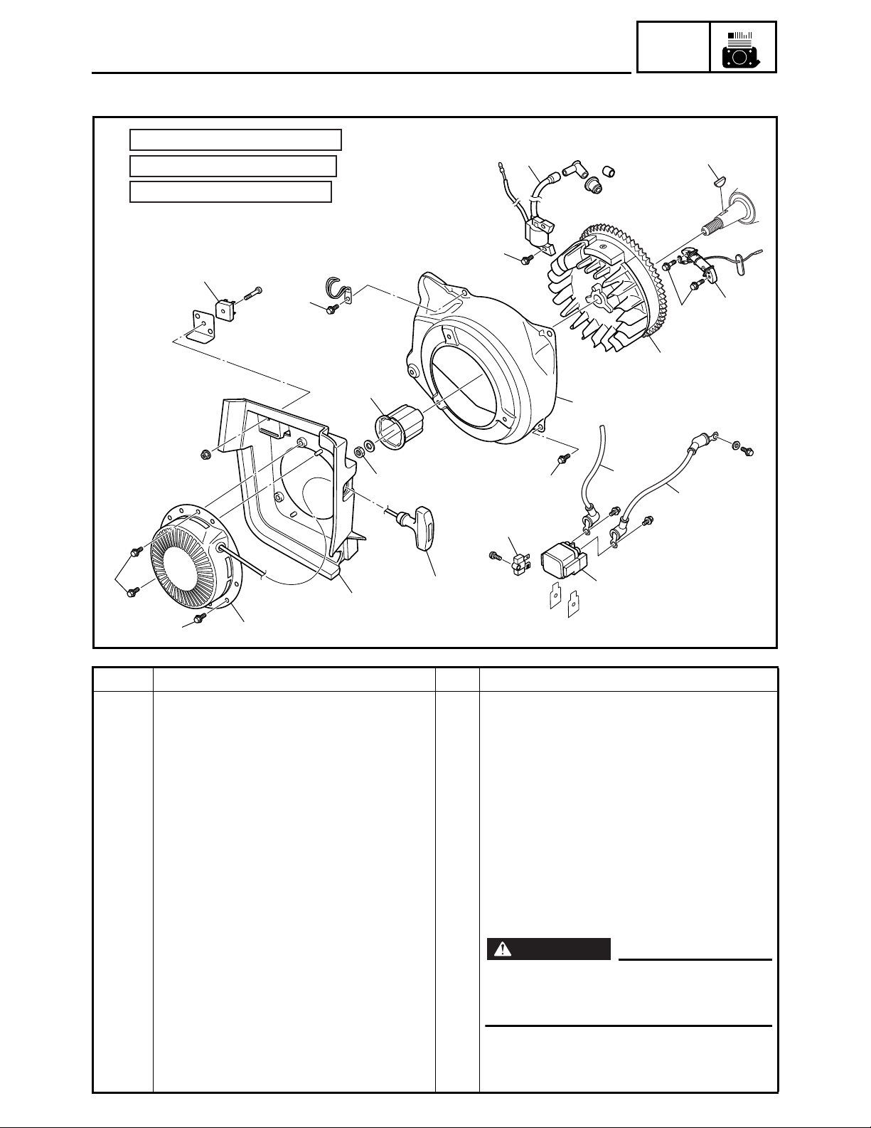
RECOIL STARTER AND FLYWHEEL MAGNETO
WARNING
RECOIL STARTER AND FLYWHEEL MAGNETO
:
7.0 Nm (0.7 m · kg, 5.1 ft · lb)
È
:
10 Nm (1.0 m · kg, 7.2 ft · lb)
É
:
65 Nm (6.5 m · kg, 47 ft · lb)
Ê
8
11
É
ENG
13
È
10
Ê
4
È
7
È
Order Job name/Part name Q’ty Remarks
Recoil starter and flywheel magneto
removal
Fuel tank Refer to “FUEL TANK AND CONTROL
Cover 3 Refer to “PANELS AND COVERS”.
Air filter assembly/control unit Refer to “AIR FILTER ASSEMBLY AND
Carburetor Refer to “CARBURETOR”.
Battery
1 Starter relay 1
2 Positive battery lead 1
6
5
Remove the parts in the order listed
below.
BOX”.
CONTROL UNIT” and “AIR FILTER
ASSEMBLY, CONTROL UNIT AND
NOISE FILTER”.
È
9
2
1
12
É
14
3
SWL3060
Remove the battery before discon-
necting the positive battery lead and
the starter motor lead.
3 Starter motor lead 1
4Rectifier 1
5 Starter handle 1
3-9

RECOIL STARTER AND FLYWHEEL MAGNETO
:
7.0 Nm (0.7 m · kg, 5.1 ft · lb)
È
:
10 Nm (1.0 m · kg, 7.2 ft · lb)
É
:
65 Nm (6.5 m · kg, 47 ft · lb)
Ê
8
É
11
ENG
13
È
10
9
Ê
È
2
4
È
5
1
7
È
6
Order Job name/Part name Q’ty Remarks
6 Recoil starter assembly 1
7 Recoil starter cover 1
8DC rectifier 1
9 Flywheel magneto cover 1
10 Starter pulley 1
11 TCI unit 1
12 Flywheel magneto 1
13 Woodruff key 1
14 Charging coil 1
NOTE:
After installing all parts, refer to “WIRE
ROUTING DIAGRAM” in CHAPTER 5 to
check the cable, lead, and hose routings.
12
É
14
3
SWL3060
3-10
For installation, reverse the removal
procedure.

RECOIL STARTER AND FLYWHEEL MAGNETO
ENG
Order Job name/Part name Q’ty Remarks
1
2
3
4
5
6
7
8
9
Recoil starter disassembly
Starter handle 1
Bolt 1
Drive plate 1
Clip 1
Drive pawl 2
Spring 2
Sheave drum 1
Starter spring 1
Starter case 1
Remove the parts in the order listed
below.
For assembly, reverse the disassembly
procedure.
SWL3070
3-11

RECOIL STARTER AND FLYWHEEL MAGNETO
RECOIL STARTER REMOVAL
1. Remove:
• Starter handle 1
NOTE:
When removing the starter handle from the
starter rope, be sure to wrap the starter rope
around a screwdriver, etc., to prevent the rope
from retracting into the starter case.
SWL3080J
ENG
1
2
FLYWHEEL MAGNETO REMOVAL
1. Remove:
• Flywheel magneto nut 1
• Washer
• Starter pulley
NOTE:
Attach the sheave holder 2 to hold the flywheel magneto.
SWL3470J
Sheave holder:
YS-01880-A, 90890-01701
Rotor assembly holder:
(commercially available)
2. Remove:
• Flywheel magneto 1
SWL3090J
NOTE:
• Remove the flywheel magneto using a bearing puller (commercially available) 2.
• When removing the flywheel magneto, be
sure to hold it so that it does not turn.
CAUTION:
Do not hold the flywheel magneto by its
fins, otherwise the fins can be damaged.
3-12

RECOIL STARTER AND FLYWHEEL MAGNETO
FLYWHEEL MAGNETO INSTALLATION
1
2
SWL3150J
1. Install:
• Woodruff key 1
• Flywheel magneto 2
CAUTION:
Be sure to remove any oil or grease from
the tapered portion of the crankshaft using
a cloth dampened with thinner.
NOTE:
Insert the woodruff key 1 into the groove in
the flywheel magneto 2.
ENG
1
2
SWL3470J
2. Install:
• Starter pulley
• Washer
• Flywheel magneto nut 1
Flywheel magneto nut:
65 Nm (6.5 m · kg, 47 ft · lb)
T
.
R
.
NOTE:
Tighten the flywheel magneto nut 1 using the
sheave holder 2 to hold the flywheel magneto.
Sheave holder:
YS-01880-A, 90890-01701
Rotor assembly holder:
(commercially available)
3. Measure:
• Air gap between TCI unit and flywheel
magneto
Refer to “AIR GAP BETWEEN TCI
UNIT AND FLYWHEEL MAGNETO” in
CHAPTER 2.
3-13
Air gap between TCI unit and flywheel magneto:
0.5 ± 0.1 mm (0.020 ± 0.004 in)

RECOIL STARTER AND FLYWHEEL MAGNETO
RECOIL STARTER DISASSEMBLY
1. Remove:
• Starter handle 1
NOTE:
Make a knot a at the end of the starter rope to
prevent the rope from being retracted into the
starter case. Then, undo the knot b at the
starter handle to the remove the starter handle
1
.
2. Remove:
• Drum sheave 1
CAUTION:
Be sure to press down on the drum sheave,
because the spring will spring out suddenly when it is removed from the sheave
drum.
1
a
b
1
SWL3100J
SWL3110J
ENG
1
1
1
2
SVU3330J
SVU3340J
3. Remove:
• Starter spring 1
RECOIL STARTER INSPECTION
1. Inspect:
• Starter rope 1
2. Inspect:
• Starter spring
2
Damage/deterioration → Replace.
3. Inspect:
• Drive pawl 1
• Drive plate 2
Wear/damage → Replace.
2
SVU3350J
3-14

RECOIL STARTER AND FLYWHEEL MAGNETO
RECOIL STARTER ASSEMBLY
1
b
1. Install:
• Starter spring 1
• Sheave drum 2
ENG
a
1
2
3
2
a
SVU3360J
b
SWL3120J
NOTE:
Engage the starter spring outer hook a with
the groove b marked “R” on the sheave drum
2
. Carefully wind the spring counterclockwise
and place it on the sheave drum 2.
2. Install:
• Sheave drum 1
• Starter rope 2
• Starter case 3
NOTE:
• Wind the starter rope 2 clockwise two turns
on the sheave drum 1.
• Engage the starter spring inner hook a with
the strut b of the starter case 3, and then
install the parts.
2
2
1
1
a
2
SVU3380J
b
a
SVU3390J
3. Install:
• Springs 1
• Drive pawls 2
NOTE:
Install the springs 1 and drive pawls 2 at the
“R” marks a.
4. Install:
• Clip 1
• Drive plate 2
NOTE:
Align the groove a of the drive plate 2 with
the sheave drum strut b, and then install the
parts.
3-15

RECOIL STARTER AND FLYWHEEL MAGNETO
ENG
1
a
b
SWL3130J
2
SWL3140J
5. Install:
• Bolt 1
After tightening the bolt, place the
starter rope 2 in the cutout a in the
sheave drum, and wind it counterclockwise four turns.
NOTE:
Make a knot b at the end of the starter rope to
prevent the rope from being retracted into the
starter case.
3-16

ENGINE ASSEMBLY
:
7.0 Nm (0.7 m · kg, 5.1 ft · lb)
È
:
16 Nm (1.6 m · kg, 11 ft · lb)
É
ENGINE ASSEMBLY
ENG
É
É
É
2
É
È
1
È
SWL3290
Order Job name/Part name Q’ty Remarks
Engine removal
Engine oil Drain.
Fuel tank Refer to “FUEL TANK AND CONTROL
Cover 6/panel 1/battery bracket Refer to “COVERS, PANELS, AND
Air filter assembly/control unit Refer to “AIR FILTER ASSEMBLY AND
Cover 3 Refer to “PANELS AND COVERS”.
Recoil starter/recoil starter cover Refer to “RECOIL STARTER AND FLY-
1 Pipe frame 1
2 Engine assembly 1
3-17
Remove the parts in the order listed below.
BOX”.
CAPS” in CHAPTER 2.
CONTROL UNIT” and “AIR FILTER
ASSEMBLY, CONTROL UNIT AND
NOISE FILTER”.
NOTE:
Remove the cover 3 with the control box
installed.
WHEEL MAGNETO”.
For installation, reverse the removal
procedure.

CHASSIS AND CASTERS
:
7.0 Nm (0.7 m · kg, 5.1 ft · lb)
È
:
16 Nm (1.6 m · kg, 11 ft · lb)
É
CHASSIS AND CASTERS
ENG
New
1
1
1
1
2
É
5
È
É
4
É
É
3
É
5
New
SWL3490
Order Job name/Part name Q’ty Remarks
Chassis and caster removal
Engine assembly Refer to “ENGINE ASSEMBLY”.
1 Engine mount 4
2Frame 1
3Caster 1 1
4Caster 2 1
5Caster 3 2
Remove the parts in the order listed
below.
For installation, reverse the removal
procedure.
3-18

MUFFLER
MUFFLER
ENG
:
3.5 Nm (0.35 m · kg, 2.5 ft · lb)
È
:
7.0 Nm (0.7 m · kg, 5.1 ft · lb)
É
:
16 Nm (1.6 m · kg, 11 ft · lb)
Ê
6
7
8
É
5
É
É
È
É
É
10
1
É
9
4
É
Ê
3
2
Order Job name/Part name Q’ty Remarks
Muffler removal
Engine assembly Refer to “ENGINE ASSEMBLY”.
1 Exhaust pipe air shroud 1 1
2 Muffler protector 1
3 Muffler 1
4Gasket 1
5 Muffler band 1
6 Muffler cap 1
7 Muffler screen 1
8 Spark arrester 1
9 Generator cover 1
10 Exhaust pipe air shroud 2 1
Remove the parts in the order listed
below.
NOTE:
Remove the muffler nut, then the muffler
bolt.
For installation, reverse the removal
procedure.
SWL3180
3-19

SWL3190J
SWL3200J
MUFFLER
ENG
MUFFLER INSTALLATION
1. Install:
• Spark arrester
NOTE:
To install the spark arrester, align the projection a on the spark arrester with the hole b in
the muffler.
2. Install:
• Muffler cap 1
NOTE:
To install the muffler cap, align the slit in the
muffler cap with the projection c on the muffler as shown in the illustration.
SWL3210J
3. Install:
• Muffler band
NOTE:
Tighten the muffler band at the angle d shown
in the illustration. Make sure that the muffler
band opening and muffler cap slit are not covering the hole b and that the muffler cap has
not come out.
d
30 ~ 60°
Muffler band:
3.5 Nm (0.35 m · kg, 2.5 ft · lb)
T
.
R
.
4. Install:
• Muffler
NOTE:
Finger tighten the muffler nut 1 and muffler
bolt 2, and then tighten them to the specified
torques, respectively.
SWL3220J
3-20
Muffler nut:
7.0 Nm (0.7 m · kg, 5.1 ft · lb)
T
.
R
.
Muffler bolt:
16 Nm (1.6 m · kg, 11 ft · lb)

GENERATOR
:
7.0 Nm (0.7 m · kg, 5.1 ft · lb)
È
:
10 Nm (1.0 m · kg, 7.2 ft · lb)
É
:
65 Nm (6.5 m · kg, 47 ft · lb)
Ê
3
É
2
GENERATOR
4
4
ENG
Ê
Order Job name/Part name Q’ty Remarks
Generator removal
Engine assembly Refer to “ENGINE ASSEMBLY”.
Muffler Refer to “MUFFLER”.
1Fan 1
2 Generator 1
É
3
1
È
Remove the parts in the order listed
below.
CAUTION:
The magnetic force of the magneto
rotor is very strong. Therefore, be sure
to remove the magneto rotor and stator coil assembly together as a set,
otherwise they may be damaged.
SWL3230
3 Tube 2
4 Dowel pin 2
3-21
For installation, reverse the removal
procedure.

SWL3240J
GENERATOR
ENG
GENERATOR ASSEMBLY REMOVAL
CAUTION:
The magnetic force of the magneto rotor is
very strong. Therefore, be sure to remove
the magneto rotor and stator coil assembly
together as a set, otherwise they may be
damaged.
1. Remove:
• Magneto rotor nut 1
NOTE:
Attach the sheave holder 2 to hold the magneto rotor.
Sheave holder:
YS-01880-A, 90890-01701
Rotor assembly holder:
(commercially available)
SWL3250J
SWL3260J
2. Remove:
• Stator coil assembly bolts 1
NOTE:
Turn the magneto rotor until the stator coil
assembly bolts are visible through the holes in
the rotor, and then remove the bolts.
3. Remove:
• Stator coil assembly bolts 2
• Tubes
NOTE:
Turn the magneto rotor until the stator coil
assembly bolts are visible through the holes in
the rotor, and then remove the bolts.
3-22

SWL3270J
GENERATOR
ENG
4. Remove:
• Generator assembly 1
NOTE:
• Remove the magneto rotor together with the
stator coil assembly using the rotor puller 2.
• Fully tighten the tool holding bolts, making
sure that the tool body is parallel with the
magneto rotor.
CAUTION:
The magnetic force of the magneto rotor is
very strong. Therefore, do not change the
position of the magneto rotor and stator
coil assembly during or after removal, otherwise they may be damaged.
Rotor puller:
YU-33270-B, 90890-01362
SWL3480J
GENERATOR ASSEMBLY INSTALLATION
CAUTION:
Be sure to remove any oil or grease from
the tapered portion of the magneto rotor
using a cloth dampened with thinner.
1. Install:
• Generator assembly
2. Install:
• Stator coil assembly bolts 1
• Tubes
Stator coil assembly bolts:
10 Nm (1.0 m · kg, 7.2 ft · lb)
T
.
R
.
NOTE:
Turn the magneto rotor until the stator coil
assembly bolts are visible though the holes in
the rotor, and then install the bolts 1.
3-23

SWL3280J
GENERATOR
ENG
3. Install:
• Stator coil assembly bolts 2
Stator coil assembly bolts:
10 Nm (1.0 m · kg, 7.2 ft · lb)
T
.
R
.
NOTE:
Turn the magneto rotor until the stator coil
assembly bolts are visible though the holes in
the rotor, and then install the bolts 2.
SWL3240J
4. Tighten:
• Washer
• Magneto rotor nut 1
Magneto rotor nut:
65 Nm (6.5 m · kg, 47 ft · lb)
T
.
R
.
NOTE:
Tighten the magneto rotor nut 1 using the
sheave holder 2.
Sheave holder:
YS-01880-A, 90890-01701
Rotor assembly holder:
(commercially available)
3-24

CYLINDER HEAD COVER AND CYLINDER HEAD
CYLINDER HEAD COVER AND CYLINDER HEAD
ENG
Order Job name/Part name Q’ty Remarks
Cylinder head cover and cylinder
head removal
Engine assembly Refer to “ENGINE ASSEMBLY”.
Muffler Refer to “MUFFLER”.
Flywheel magneto Refer to “RECOIL STARTER AND FLY-
1 Spark plug cap 1
2 Spark plug 1
3 Breather hose 1
4 Cylinder head cover 1
5Gasket 1
6 Air shroud 1
7 Cylinder head assembly 1
8 Cylinder head gasket 1
9 Dowel pin 2
10 Push rod 2
Remove the parts in the order listed
below.
WHEEL MAGNETO”.
For installation, reverse the removal
procedure.
SWL3320
3-25
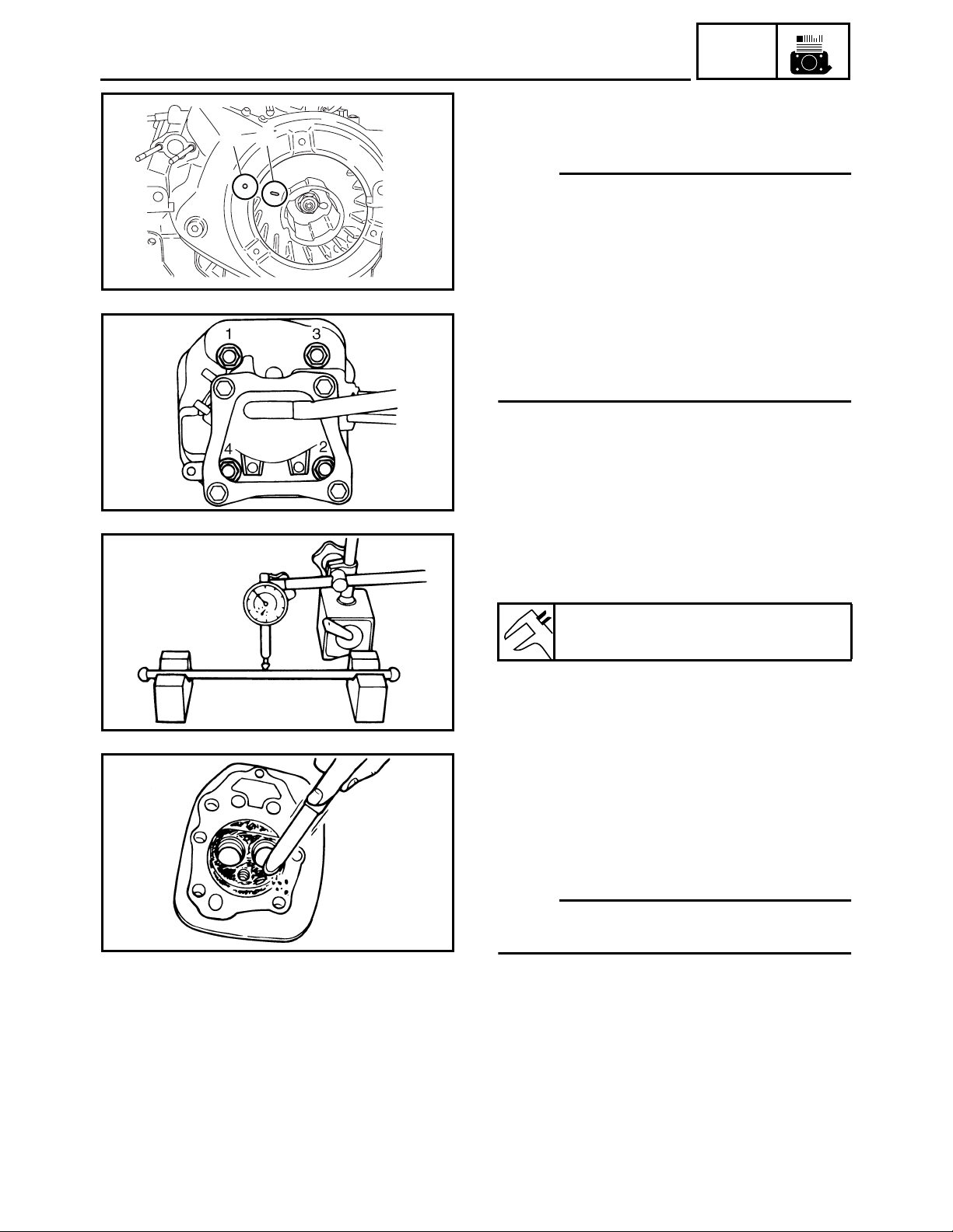
CYLINDER HEAD COVER AND CYLINDER HEAD
CYLINDER HEAD REMOVAL
1. Remove:
a
b
SWL3450
SWL3330J
• Cylinder head
NOTE:
• Rotate the crankshaft clockwise until the
mark a on the flywheel magneto is parallel
with the punch mark b. This is the condition
in which the piston is at top dead center of
the compression stroke.
• If the piston is at top dead center of the
exhaust stroke, turn the crankshaft one full
turn (360°) to set the piston at top dead center of the compression stroke.
• Loosen the nuts in the proper sequence.
ENG
SVU3100J
SVU3110J
PUSH ROD INSPECTION
1. Measure:
• Push rod runout
Runout limit:
0.5 mm (0.02 in)
Out of specification → Replace.
CYLINDER HEAD INSPECTION
1. Inspect:
• Cylinder head combustion chamber
Check the combustion chamber for carbon deposits
Carbon deposits → Remove.
NOTE:
Be sure not to damage the contact surface of
the cylinder.
2. Inspect:
• Cylinder head
Cracks or damage around the spark
plug hole → Replace.
3-26

CYLINDER HEAD COVER AND CYLINDER HEAD
3. Measure:
• Cylinder head warpage
Measure the warpage on the contact
surface of the cylinder head at six
points using a straightedge and thickness gauge.
Warpage limit:
0.05 mm (0.0020 in)
SVU3120J
Out of specification → Resurface or
replace.
ENG
SWL3340J
CYLINDER HEAD ASSEMBLY
1. Install:
• Cylinder head bolts 1 to 4.
NOTE:
Tighten the bolts to the specified torques in
two steps and in order from 1 to 4.
Cylinder head bolts:
1st: 12 Nm (1.2 m · kg, 8.7 ft · lb)
T
.
R
.
2nd: 20 Nm (2.0 m · kg, 14 ft · lb)
BREATHER HOSE
1. Inspect:
• Breather hose 1
SVU3140J
NOTE:
Contact the end of the breather hose to the
reed valve stopper a.
3-27

VALVE
VALVE
ENG
Order Job name/Part name Q’ty Remarks
Valve removal
Cylinder head assembly Refer to “CYLINDER HEAD COVER AND
1 Locknut 2
2Adjuster 2
3 Locker arm 2
4 Valve cotter 2
5 Valve spring retainer 2
6 Valve spring 2
7 Valve (intake) 1
8 Valve (exhaust) 1
9 Valve stem seal 1
Remove the parts in the order listed
below.
CYLINDER HEAD”.
For installation, reverse the removal
procedure.
SWL3350
3-28

SVU3160J
VALVE
ENG
VALVE AND VALVE SPRING REMOVAL
1. Remove:
• Valve cotter 1
• Valve spring retainer 2
• Valve spring 3
• Valve 4
Remove the parts using the valve
spring compressor 5.
CAUTION:
Do not compress the valve spring more
than necessary.
Valve spring compressor:
YM-01253, 90890-01253
SVU3170J
VALVE AND VALVE SPRING INSPECTION
1. Measure:
• Valve stem length a
• Valve face diameter b
Valve stem length:
Intake: 65.9 mm (2.59 in)
Exhaust: 66.2 mm (2.61 in)
Valve face diameter:
Intake: 23.9 ~ 24.1 mm
(0.9409 ~ 0.9488 in)
Exhaust: 21.9 ~ 22.1 mm
(0.8622 ~ 0.8701 in)
Out of specification → Replace.
2. Measure:
• Valve stem diameter
a
Valve stem diameter:
Intake: 5.448 ~ 5.463 mm
(0.2145 ~ 0.2151 in)
Exhaust: 5.440 ~ 5.445 mm
(0.2142 ~ 0.2144 in)
Wear limit:
Intake: 5.418 mm (0.2133 in)
Exhaust: 5.410 mm (0.2130 in)
SVU3180J
Out of specification → Replace.
3-29

SVU3190J
SVU3200J
VALVE
ENG
3. Measure:
• Valve stem runout
Runout limit:
0.01 mm (0.0004 in)
Out of specification → Replace.
NOTE:
The value is half of that indicated on the dial
gauge.
4. Measure:
• Valve spring free length a
Valve spring free length:
Intake and exhaust:
26.5 mm (1.04 in)
Limit: 25.2 mm (0.99 in)
Out of specification → Replace.
SVU3210J
SVU3220J
5. Measure:
• Valve spring tilt a
Tilt limit:
2.5°/1.6 mm (0.06 in)
Out of specification → Replace.
6. Inspect:
• Valve spring contact surface
More than 2/3 of the contact surface
does not contact → Replace.
LOCKER ARM INSPECTION
1. Inspect:
• Locker arm
Wear/damage/cracks → Replace.
SVU3230J
3-30

VALVE
ENG
VALVE SEAT INSPECTION
1. Remove carbon deposits from the valve
face and valve seat.
2. Apply a small amount of coarse
Mechanic’s blueing dye (Dykem) to the
valve face.
3. Insert the valve into the valve guide and
use a valve lapper to contact the valve
face with the valve seat.
NOTE:
Do not rotate the valve while the valve face is
contacting the valve seat.
4. Measure:
• Valve face contact width
a
Make sure that the contact width along
the entire valve face is within specifications.
SVU3240J
SVU3250J
Valve face contact width (intake
and exhaust):
0.9 ~ 1.1 mm (0.0354 ~ 0.0433 in)
Limit: 1.6 mm (0.0630 in)
Out of specification/rough/eccentric
wear → Replace.
5. Measure:
• Valve seat contact width
a
Make sure that the contact width along
the entire valve seat is within specifications.
Valve seat contact width (intake
and exhaust):
0.9 ~ 1.1 mm (0.0354 ~ 0.0433 in)
Limit: 1.6 mm (0.0630 in)
3-31
Out of specification/rough/eccentric
wear → Replace.

SVU3270
VALVE
ENG
6. Remove the carbon deposits on the valve
face a and valve seat.
• Valve face contact seat width b
• Valve margin thickness c
Apply a small amount of coarse
Mechanic’s blueing dye (Dykem) to the
valve seat.
Press the valve through the valve guide
and onto the valve seat to make a clear
impression.
• Valve margin thickness
Out of specification → Replace.
• Valve face contact width
Out of specification → Replace.
Valve seat width:
0.9 ~ 1.1 mm (0.0354 ~ 0.0433 in)
Valve margin thickness:
0.3 mm (0.012 in)
SVU3270J
VALVE LAPPING
1. Apply a coarse lapping compound evenly
on the valve face. Lap the valve by tapping and rotating the valve lapper
1
clockwise and counterclockwise.
2. Clean off all of the lapping compound
from the valve face and valve seat. Apply
fine lapping compound on the valve face
and lap the valve as in step 1.
3. If the contact width on the valve face
shines white along the entire face, apply
Mechanic’s blueing dye (Dykem) to make
sure that there are traces of even contact
in the center of the valve face.
CAUTION:
Do not let the lapping compound enter the
gap between the valve stem and the valve
guide.
NOTE:
After every lapping procedure, clean off the
compound from the valve face and valve seat.
3-32

SVU3280J
VALVE
VALVE AND VALVE SPRING ASSEMBLY
1. Install:
• Valve 1
• Valve spring 2
• Valve spring retainer 3
• Valve cotter 4
Apply a small amount of molybdenum
disulfide oil to the valve stem and use
the valve spring compressor 5 to
install the parts.
Valve spring compressor:
YM-01253, 90890-01253
NOTE:
Install the chamfered side of the valve cotter
facing down.
ENG
New
CAUTION:
Do not compress the valve spring more
than necessary.
3-33

CRANKCASE COVER AND CAMSHAFT
CRANKCASE COVER AND CAMSHAFT
ENG
Order Job name/Part name Q’ty Remarks
Crankcase cover and camshaft
removal
Engine assembly Refer to “ENGINE ASSEMBLY”.
Cylinder head assembly Refer to “CYLINDER HEAD COVER AND
Flywheel magneto Refer to “RECOIL STARTER AND FLY-
Generator assembly Refer to “GENERATOR”.
1 Crankcase cover 1
2Gasket 1
3 Rubber seal 2
4 Dowel pin 2
5Bracket 1
6 Oil level switch 1
7Camshaft 1
8 Valve lifter 2
Remove the parts in the order listed
below.
CYLINDER HEAD”.
WHEEL MAGNETO”.
For installation, reverse the removal
procedure.
SWL3360
3-34

CRANKCASE COVER AND CAMSHAFT
ENG
CRANKCASE COVER REMOVAL
6
4
1. Remove:
• Crankcase cover
NOTE:
1
2
Loosen the bolts in the proper sequence.
3
5
SWL3370J
CAMSHAFT INSPECTION
1. Inspect:
• Camshaft
Damage → Replace.
SVU3480J
2. Measure:
• Cam lobes length a and b
Out of specifications → Replace.
Cam lobes length:
Intake
: 26.9 ± 0.05 mm
a
(1.059 ± 0.002 in)
: 22.0 ± 0.05 mm
b
(0.866 ± 0.002 in)
SVU3490J
Exhausta: 26.68 ± 0.05 mm
(1.050 ± 0.002 in)
: 22.025 ± 0.05 mm
b
(0.867 ± 0.002 in)
SVU3500J
SVU3510J
3. Inspect:
• Surface of camshaft gear teeth
• Decompressor
Wear/damage → Replace.
4. Measure:
• Camshaft diameter a
Out of specification → Replace.
Camshaft diameter:
14.965 ~ 14.990 mm
(0.5892 ~ 0.5902 in)
Wear limit:
14.950 mm (0.5886 in)
3-35

CRANKCASE COVER AND CAMSHAFT
VALVE LIFTER INSPECTION
1. Inspect:
• Valve lifter
Damage → Replace.
SVU3520J
CAMSHAFT ASSEMBLY
1. Install:
• Camshaft 1
CAUTION:
Be sure to align the hole a in the camshaft
gear with the crankshaft gear mark b.
SVU3530J
ENG
CRANKCASE COVER INSPECTION
1. Inspect:
1
2
• Crankcase cover 1
Damage → Replace.
• Bearing 2
Noise/wear/rotational failure →
Replace.
SWL3380J
CRANKCASE COVER INSTALLATION
1
3
1. Install:
• Crankcase cover bolts 1 to 6
NOTE:
6
5
Tighten the bolts to the specified torques in
two steps and in order from 1 to 6.
Crankcase cover bolts:
4
2
SWL3390J
1st: 12 Nm (1.2 m · kg, 8.7 ft · lb)
T
.
R
.
2nd: 22 Nm (2.2 m · kg, 16 ft · lb)
3-36

PISTON, CONNECTING ROD, CRANKSHAFT AND
CRANKCASE
ENG
PISTON, CONNECTING ROD, CRANKSHAFT AND CRANKCASE
Order Job name/Part name Q’ty Remarks
Piston, connecting rod, crankshaft
and crankcase removal
Engine assembly Refer to “ENGINE ASSEMBLY”.
Cylinder head assembly Refer to “CYLINDER HEAD COVER AND
Flywheel magneto Refer to “RECOIL STARTER AND FLY-
Generator assembly Refer to “GENERATOR”.
Crankcase cover/camshaft Refer to “CRANKCASE COVER AND
1 Connecting rod cap 1
2 Crankshaft 1
3 Connecting rod 1
4 Piston pin circlip 2
5 Piston pin 1
6Piston 1
7 Piston ring 3
Remove the parts in the order listed
below.
CYLINDER HEAD”.
WHEEL MAGNETO”.
CAMSHAFT”.
For installation, reverse the removal
procedure.
SWL3500
3-37

PISTON, CONNECTING ROD, CRANKSHAFT AND
CRANKCASE
CRANKCASE (CYLINDER) INSPECTION
1. Measure:
• Cylinder inside diameter
NOTE:
Take side to side a and front to back b measurements at each of the three locations A, B,
and C (total of six measurements), and then
find the average of the measurements.
Maximum wear = Maximum A, B, C
Cylinder taper = Maximum A – Minimum C
Out of specification → Replace.
Cylinder inside diameter:
66.005 ~ 66.015 mm
(2.5986 ~ 2.5990 in)
Cylinder inside diameter wear
limit:
66.020 mm (2.5992 in)
Cylinder taper limit:
SVU3590
0.05 mm (0.0020 in)
ENG
SVU3580J
2. Measure:
• Cylinder warpage
NOTE:
Measure the warpage on the contact surface
of the cylinder head at six points using a
straightedge and thickness gauge.
Out of specification → Resurface or
replace.
Warpage limit:
0.05 mm (0.0020 in)
PISTON AND PISTON PIN INSPECTION
1. Measure:
• Piston skirt diameter P
= 10 mm (0.4 in) from the piston bottom edge
a
Out of specification → Replace.
SVU3590J
Piston skirt diameter:
65.975 ~ 65.990 mm
(2.5974 ~ 2.5980 in)
Wear limit:
65.9 mm (2.5945 in)
3-38

PISTON, CONNECTING ROD, CRANKSHAFT AND
CRANKCASE
2. Measure:
• Piston clearance
Out of specification → Rebore or
replace cylinder and replace piston and
piston rings.
Piston clearance:
0.015 ~ 0.040 mm
(0.00059 ~ 0.00157 in)
Wear limit:
0.15 mm (0.00591 in)
Piston clearance =
Cylinder inside diameter –
Piston skirt diameter
ENG
SVU3600J
SVU3610J
SVU3620J
3. Measure:
• Piston pin hole inside diameter
Out of specification → Replace.
Piston pin hole inside diameter:
16.002 ~ 16.013 mm
(0.6300 ~ 0.6304 in)
Wear limit:
16.043 mm (0.6316 in)
4. Measure:
• Piston pin diameter
Out of specification → Replace.
Piston pin diameter:
15.995 ~ 16.000 mm
(0.6297 ~ 0.6299 in)
Wear limit:
16.043 mm (0.6316 in)
5. Inspect:
• Check that the piston pin enters
smoothly into the piston pin hole.
If the piston pin fits tightly into the piston, check the piston pin hole. If there is
any protrusion, use a knife or scraper to
gently remove it so that the piston pin
can be pushed in gently with your fingers.
3-39

PISTON, CONNECTING ROD, CRANKSHAFT AND
CRANKCASE
PISTON RING INSPECTION
1. Measure:
• Piston ring end gap
Out of specification → Replace.
NOTE:
Insert the piston ring 1 into the cylinder, and
push it approximately 5 mm (0.2 in) into the cylinder. Push in the ring with the piston crown so that
SVU3630J
the ring is at right angles to the cylinder bore.
Ring end gap Wear limit
ENG
SVU3640J
Top ring
2nd ring
Oil ring
2. Measure:
• Piston ring side clearance
Out of specification → Replace.
Use a thickness gauge 1.
Top ring
2nd ring
0.20 ~ 0.40 mm
(0.0079 ~ 0.0157 in)
0.20 ~ 0.40 mm
(0.0079 ~ 0.0157 in)
0.20 ~ 0.70 mm
(0.0079 ~ 0.0276 in)
Piston ring side
clearance
0.04 ~ 0.08 mm
(0.0016 ~
0.0031 in)
0.02 ~ 0.06 mm
(0.0008 ~
0.0024 in)
0.65 mm
(0.0256 in)
0.75 mm
(0.0295 in)
0.9 mm
(0.0354 in)
Wear limit
0.13 mm
(0.0051 in)
0.12 mm
(0.0047 in)
NOTE:
• Clean carbon deposits from the piston ring
grooves and rings before measuring the
side clearance.
• Measure the side clearance at several portions.
3-40

PISTON, CONNECTING ROD, CRANKSHAFT AND
CRANKCASE
CRANKSHAFT INSPECTION
1. Measure:
• Crankshaft runout limit
Use a dial gauge.
Out of specification → Replace.
Runout limit:
0.02 mm (0.0008 in)
SWL3510J
2. Inspect:
1
• Crankshaft gear 1
Wear/damage → Replace.
ENG
SWL3520J
SWL3530J
3. Measure:
• Crankshaft pin outside diameter
Wear/damage → Replace.
Use a micrometer.
Out of specification → Replace.
Crankshaft pin outside diameter:
27.969 ~ 27.984 mm
(1.1011 ~ 1.1017 in)
Wear limit:
27.9 mm (1.0984 in)
a
3-41

PISTON, CONNECTING ROD, CRANKSHAFT AND
CRANKCASE
CONNECTING ROD OIL CLEARANCE
INSPECTION
NOTE:
Measure the oil clearance if replacing the
crankshaft or connecting rod.
1. Place a piece of Plastigauge 1 on the
crankshaft pin horizontally.
ENG
SVU3680J
SVU3690J
SVU3700J
NOTE:
Clean off oil from all parts thoroughly.
2. Install:
• Connecting rod 1
• Connecting rod cap 2
NOTE:
Tighten the cap bolts so that the crankshaft
does not move while the oil clearance is being
measured.
Connecting rod cap bolt:
12 Nm (1.2 m · kg, 8.7 ft · lb)
T
.
R
.
3. Remove:
• Connecting rod cap
• Connecting rod
4. Measure:
• Widest portion of the pressed Plasti-
gauge
Out of specification → Replace crankshaft or connecting rod, and then measure the clearance again.
3-42
Connecting rod big end oil clearance:
0.015 ~ 0.040 mm
(0.0006 ~ 0.0016 in)
Wear limit:
0.1 mm (0.0039 in)

PISTON, CONNECTING ROD, CRANKSHAFT AND
CRANKCASE
PISTON RING AND PISTON ASSEMBLY
1. Install:
• Top ring 1
• 2nd ring 2
• Oil ring 3
NOTE:
• Be sure to install the second ring so that the
manufactures mark a faces towards the
piston head.
• Make sure that the piston rings move
smoothly.
2. Apply 4-stroke engine oil to the inside of
the connecting rod small end.
ENG
SVW3770
SVU3720J
3. Install:
• Piston 1
• Piston pin 2
• Piston pin circlip 3
New
NOTE:
• Make sure that the “YAMAHA” mark a on
the connecting rod faces toward the crankcase cover.
• Make sure that the “” mark b on the pis-
ton head faces toward the push rod.
3-43

PISTON, CONNECTING ROD, CRANKSHAFT AND
CRANKCASE
CRANKSHAFT ASSEMBLY
1. Make sure that the end gap of each piston
ring is positioned, as shown in the illustration.
Top ring a
2nd ring b
ENG
SVU3750J
SVU3730J
SVU3740J
Oil ring c
2. Install:
• Piston ring compressor 1
Piston ring compressor:
YU-33294, 90890-05158
3. Install:
• Connecting rod 1
• Piston 2
NOTE:
• Make sure that the “” mark a on the pis-
ton head faces toward the push rod.
• Make sure that the “YAMAHA” mark b on
the connecting rod faces toward the crankcase cover.
SVU3760J
4. Install:
• Crankshaft
• Connecting rod cap
NOTE:
Make sure that the “” mark a on the connecting rod is aligned with the “” mark b on
the rod cap.
Connecting rod cap bolt:
12 Nm (1.2 m · kg, 8.7 ft · lb)
T
.
R
.
5. Install:
• Camshaft
• Crankcase cover
Refer to “CRANKCASE COVER AND
CAMSHAFT”.
3-44

CARBURETOR
CARBURETOR
ENG
Order Job name/Part name Q’ty Remarks
Carburetor removal
Panel 4/cover 5 Refer to “COVERS, PANELS, AND
Slide the fuel tank Refer to “FUEL TANK AND CONTROL
Air filter assembly Refer to “AIR FILTER ASSEMBLY AND
1 Choke cable 1
2 Choke knob 1
3 Fuel hose 1
4 Throttle control motor cover 1
5 Throttle control motor coupler 1
6 Carburetor 1
7Gasket 1
Remove the parts in the order listed
below.
CAPS” in CHAPTER 2.
BOX”.
CONTROL UNIT” and “AIR FILTER
ASSEMBLY, CONTROL UNIT AND
NOISE FILTER”.
SWL3400
3-45

CARBURETOR
ENG
Order Job name/Part name Q’ty Remarks
8 Carburetor joint 1
9Gasket 1
For installation, reverse the removal
procedure.
SWL3400
3-46

CARBURETOR
ENG
Order Job name/Part name Q’ty Remarks
1
2
3
4
5
6
7
8
9
Carburetor disassembly
Throttle control motor assembly 1
Throttle controller bracket 1
Bracket 1
Drain hose 1
Bolt 1
Gasket 1
Drain screw 1
Float chamber 1
Gasket 1
3-47
Remove the parts in the order listed
below.
SWL3410

CARBURETOR
ENG
Order Job name/Part name Q’ty Remarks
0
A
B
C
D
E
F
G
H
Float pin 1
Float 1
Needle valve 1
Main nozzle 1
Main jet 1
Air vent hose 1
Throttle stop screw 1
Pilot screw 1
Pilot jet 1
For assembly, reverse the disassembly
procedure.
3-48
SWL3410

SVU3790J
SVU3800J
CARBURETOR
ENG
FLOAT HEIGHT INSPECTION
1. Measure:
• Float height
Out of specification → Replace.
NOTE:
Lift up the float height so that the tip of the needle valve lightly contacts the float arm, and
then measure the float height a. (This measurement should be made with the gasket
removed.)
Float height:
16.0 mm (0.63 in)
SVU3810J
SVU3820J
2. Clean:
• Carburetor body
Blow out all passages, jets, and carburetor body with compressed air.
3. Inspect:
• Valve seat
Wear/damage → Replace.
Dirt → Clean.
Wear at groove
1
Dirt
2
3-49

1
5
2
3
a
6
CARBURETOR
ENG
CHOKE CABLE INSTALLATION
1. Inspect:
• Choke knob 1
NOTE:
Push the choke knob 1 entirely in before
installing it to the frame.
2. Install:
• Casing cap (choke cable) 2
NOTE:
Place the choke knob casing cap against the
stay 3.
3. Install:
• Inner cable 4
NOTE:
Place the carburetor choke valve in its fully
open position a, insert the tip of the inner
cable into the drum hole 5, and then secure it
in place with the screw 6.
Screw:
1.0 Nm (0.1 m · kg, 0.7 ft · lb)
T
.
R
.
b
a
1
4
SWL3420J
SVU3840J
THROTTLE CONTROL MOTOR
1. Inspect:
• Throttle control motor 1
NOTE:
• Install the shaft a of the throttle control
motor by aligning it with the groove
b of the
throttle shaft.
• Install the throttle valve, and then make sure
that is moves smoothly.
• When installing the engine, fully open the
throttle valve.
3-50

TROUBLESHOOTING
ENGINE DOES NOT START
TROUBLESHOOTING
ENG
Check that the oil level
warning light turns on by
pulling the starter rope.
LIGHT ON
Check engine oil level.
SUFFICIENT
Check fuel level.
SUFFICIENT
Check if fuel is deteriorated.
GOOD NOT GOOD Replace.
Check fuel cock lever position.
“ON”“OFF” Set to “ON”.
Check if fuel travels to fuel
cock.
GOOD NOT GOOD
Remove spark plug, attach
it to spark plug cap, and
then ground the spark plug
to check for spark.
GOOD
SPARK
DOSE NOT
TURN ON
INSUFFI-
CIENT
INSUFFI-
CIENT
WEAK OR
NO SPARK
Check connections between engine
speed limiter/oil level warning unit and oil
level switch.
GOOD NOT GOOD
• Check spark plug for dirt and check
spark plug gap.
• Check for voltage leakage due to faulty
connection or broken insulation of the
spark plug lead.
• Check TCI unit coupler for corrosion or
faulty connection.
• Check the ignition system. Refer to
“IGNITION SYSTEM” in CHAPTER 4.
GOOD NO GOOD
Replace oil level
warning light,
engine speed limiter/oil level warning
unit, or oil level
switch.
Add.
Add.
Clean fuel tank, fuel
cock, and fuel pipe
strainer.
Clean.
Correct.
Replace.
Check carburetor for
clogged passages or fuel
overflow.
GOOD NO GOOD Clean.
Check compression using
compression gauge.
OUT OF
SPECIFICA-
TION
GOOD
*
3-51

TROUBLESHOOTING
ENG
*
Measure valve clearance.
OUT OF
GOOD
Check valve face and valve
seat for wear.
GOOD WEAR
Check if the timing marks
on the crankshaft and camshaft are aligned.
GOOD NO GOOD Correct or replace.
Check if there is seizure or
wear on the piston, piston
ring, or cylinder.
GOOD
SPECIFICA-
TION
SEIZURE
OR WEAR
Adjust.
Resurface or
replace.
Rebore or replace.
Check the condition of the throttle control
system. Refer to “THROTTLE CONTROL
SYSTEM”.
3-52

TROUBLESHOOTING
ENG
ENGINE STARTS BUT STALLS
Check fuel level.
SUFFICIENT
Check if fuel cock is
clogged.
GOOD NO GOOD Clean.
Check if fuel pipe, fuel hose
and fuel pipe strainer are
clogged.
GOOD NO GOOD Clean.
INSUFFI-
CIENT
Add.
• Check if carburetor
retaining nuts are loose.
• Check if there is air suction due to a damaged
carburetor joint or gasket.
GOOD NO GOOD
Measure valve clearance.
OUT OF
GOOD
Check compression using
a compression gauge.
GOOD
Check if there are air gap
between TCI unit and flywheel magneto.
GOOD
SPECIFICA-
TION
OUT OF
SPECIFICA-
TION
OUT OF
SPECIFICA-
TION
Improperly tightened cylinder head
• Tighten the carburetor bolts
securely.
• Replace carburetor joint or gasket
with a new one.
Adjust.
Tighten securely.
Adjust.
Check the condition of the throttle control
system. Refer to “THROTTLE CONTROL
SYSTEM”.
3-53

TROUBLESHOOTING
ENG
ENGINE SPEED DOES NOT INCREASE
Check if the electric equipment
consumes too much wattage for
this generator.
GOOD TOO MUCH Use a generator with a larger capacity.
Check air filter element for dirt.
GOOD NOT GOOD Clean.
Check spark plug for dirt and
check spark plug gap.
GOOD NOT GOOD Clean or adjust.
Check valve clearance.
GOOD
Check if main passages such as,
the main jet, in the carburetor are
clogged.
GOOD NO GOOD Disassemble or clean.
OUT OF SPECI-
FICATION
Adjust.
Check for air suction due to a
damaged throttle shaft seal, carburetor joint, or gasket.
GOOD NO GOOD Disassemble or replace.
Check compression using compression gauge.
GOOD
**
Check if the timing marks on the
crankshaft and camshaft are
aligned.
GOOD NO GOOD Correct.
Check valve face and valve seat
for wear.
GOOD WEAR Resurface or replace.
Check if there is seizure or wear
on piston, piston ring, or cylinder.
GOOD
TOO HIGH Decarbonize combustion chamber if there are
TOO LOW
SEIZURE OR
WEAR
carbon deposits.
Rebore or replace.
Check the condition of the throttle
**
control system. Refer to “THROT-
TLE CONTROL SYSTEM”.
3-54

TROUBLESHOOTING
ENGINE SPEED IS UNEVEN
Check fuel level.
SUFFICIENT INSUFFICIENT Add.
Check if fuel is deteriorated.
GOOD NO GOOD Replace.
Check if fuel cock, fuel pipe, fuel
hose and fuel pipe strainer are
clogged.
GOOD NO GOOD Clean.
Check spark plug for dirt and
check spark plug gap.
GOOD NO GOOD Clean or adjust.
Measure valve clearance.
GOOD
OUT OF SPECI-
FICATION
Adjust.
ENG
While the engine is operating, pull
the choke knob approximately 1/3
to 1/2 way out, and then check the
engine operating condition.
STABLE UNSTABLE
**
Check for air suction due to a
damaged throttle shaft seal, carburetor joint, or gasket.
GOOD NO GOOD Disassemble or replace.
Check if slow or main passages
such as, the pilot jet and main jet,
in the carburetor are clogged.
GOOD NO GOOD Disassemble or clean.
Check valve face and valve seat
**
for wear.
GOOD WEAR Resurface or replace.
Check if there is seizure or wear
on the piston, piston ring, or cylinder.
GOOD
SEIZURE OR
WEAR
Rebore or replace.
Check the condition of the throttle
control system. Refer to “THROT-
TLE CONTROL SYSTEM”.
3-55

TROUBLESHOOTING
ENG
THROTTLE CONTROL SYSTEM
ENGINE DOES NOT START, ENGINE STARTS BUT STALLS, ENGINE SPEED
DOES NOT INCREASE, OR ENGINE SPEED IS UNEVEN.
Check AC output.
GOOD NO GOOD Refer to “GENERATOR SYSTEM” in CHAPTER 4.
Rotate the shaft of the throttle control
motor to check if it turns smoothly with
slight resistance.
GOOD NO GOOD Replace the throttle control motor.
Measure the coil resistance between 3-1,
3-2, 3-4, and 3-5 of the throttle control
motor. (Tester range: Ω × 100)
250 Ω ± 7% /25 °C (77 °F)
54321
1
5
3
2
GOOD
Check the connections of the wire harness connectors and couplers, and the
wires for an open circuit or short circuit.
GOOD NO GOOD Correct or replace.
Defective control unit.
Replace the control unit.
OUT OF SPECIFI-
CATION
4
SVU3850J
Replace the throttle control motor.
3-56

TROUBLESHOOTING
ENG
WITH NO LOAD, ENGINE SPEED DOES NOT INCREASE WHEN ECONOMY CONTROL
SWITCH IS SET TO “OFF” “”.
WITH NO LOAD, ENGINE SPEED DOES NOT DECREASE WHEN ECONOMY CONTROL
SWITCH IS SET TO “ON” “”.
WITH LOAD, ENGINE SPEED DOES NOT INCREASE WHEN ECONOMY CONTROL SWITCH
IS SET TO “ON” “”.
Check AC output.
GOOD NO GOOD Refer to “GENERATOR SYSTEM” in CHAPTER 4.
Check condition of the throttle control motor.
GOOD NO GOOD Replace throttle control motor.
Check economy switch.
GOOD NO GOOD Replace economy switch.
Check the connections of the wire
harness connectors and couplers,
and the wires for an open circuit or
short circuit.
GOOD NO GOOD Correct or replace.
Defective control unit.
Replace the control unit.
3-57

C
B
A
0
9
8
3
2
ELECTRICAL COMPONENTS
ELECTRICAL
ELECTRICAL COMPONENTS
120 V-60 Hz
Generator assembly
1
Oil level switch
2
Starter motor
3
Control unit
4
Charging coil
5
Starter relay
6
Rectifier
7
Battery
8
Flywheel magneto
9
TCI unit
0
Spark plug
A
Throttle control motor
B
DC rectifier
C
Main switch
D
Economy switch
E
Engine speed limiter/oil level warning unit
F
DC circuit breaker
G
DC receptacle (12 V, 8.3 A)
H
AC switch (NFB) (15 A)
I
AC switch (NFB) (23.5 A)
J
AC receptacle (15 A × 2)
K
AC receptacle (23.3 A)
L
Ground terminal
M
Overload warning light (Red)
N
Pilot light (Green)
O
Oil level warning light (Red)
P
7
1
SWL4090T
4
5
6
SWL4080T
ELEC
– +
D
P
E
F
G
H
K
J
I
M
NO
L
SWL4010T
4-1

C
B
A
0
9
8
3
2
ELECTRICAL COMPONENTS
220 V-50 Hz
Generator assembly
1
Oil level switch
2
Starter motor
3
Control unit
4
Charging coil
5
Starter relay
6
Rectifier
7
Battery
8
Flywheel magneto
9
TCI unit
0
Spark plug
A
Throttle control motor
B
DC rectifier
C
Main switch
D
Economy switch
E
Engine speed limiter/oil level warning unit
F
DC receptacle (12 V, 12 A)
G
AC receptacle (15 A × 2)
H
Ground terminal
I
Overload warning light (Red)
J
Pilot light (Green)
K
DC circuit breaker
L
Oil level warning light (Red)
M
7
1
SWL4090T
4
5
6
SWL4080T
ELEC
– +
D
E
F
ML
G
H
SWL4020T
I
JK
4-2
 Loading...